Abstract
Acid fracturing is a crucial method for reservoir reconstruction in carbonate reservoirs, and the propagation pattern of acid-etched fractures plays a key role in determining the scope of reservoir enhancement and post-fracturing productivity. However, large-scale physical simulations directly using acid solutions in fracturing experiments are limited, and the fracture propagation patterns under acid fracturing remain unclear. To address this gap, in this study, we collected carbonate rock samples from the Majiagou Formation in the Daniudi area, preparing large-scale fracturing specimens with side lengths of 30 cm. The propagation of acid fracturing fractures was investigated using self-developed true-triaxial acid fracturing equipment. Based on post-fracturing fracture morphology and pressure curves, the effects of fracturing fluid type, injection rate, injection mode, and natural fractures (NFs) on acid fracturing fracture propagation were analyzed. The experimental results showed that the acid solution effectively weakens the mechanical properties of the open-hole section, creating multiple mechanical weak points and promoting the initiation of fractures. Pre-fracturing treatment with low-viscosity acid can significantly enhance fracture complexity near the wellbore and expand the near-well stimulation zone. Lowering the injection rate increases the acid solution’s filtration loss into natural fractures, weakening the cementation strength of these fractures and encouraging the formation of complex fracture networks. Furthermore, employing a multi-stage alternating injection of high-viscosity and low-viscosity acids can reduce fracture temperature and acid filtration loss while also enhancing differential etching through viscous fingering. This approach improves the conductivity and conductivity retention of the acid-etched fractures. The results of this study can provide a reference for the acid fracturing stimulation of fractured carbonate reservoirs.
1. Introduction
Common techniques for stimulating carbonate reservoirs include matrix acidizing and acid fracturing. Matrix acidizing involves injecting an acid solution at a pressure lower than the formation fracture pressure. The acid then flows through the formation, reacting with the rock to form wormholes that bypass the damaged zone, thereby restoring or enhancing productivity by improving access to the near-wellbore region. This technique is typically employed in reservoirs with favorable formation properties [1,2]. However, for deep carbonate reservoirs, the physical properties of the formation are typically poor due to sedimentary compaction [3]. Therefore, acid fracturing is required to create high-conductivity flow channels in the formation, increasing the seepage area and ultimately enhancing production. Unlike hydraulic fracturing, acid fracturing does not rely on proppants. Instead, it generates fractures with high conductivity through the chemical reaction between the acidic fracturing fluid and the minerals on the surface of carbonate rock fractures [4,5]. The effectiveness of acid fracturing stimulation depends on the length, coverage area, and conductivity of the acid-etched fractures [6,7,8]. As the primary pathways for acid flow and subsequent oil and gas production, studying the propagation process and morphology of acid-etched fractures is crucial for the design and optimization of acid fracturing treatments.
The propagation of acid fracturing fractures is a coupled process involving multiple fields, including the flow and reaction of the acid solution, as well as the compressive deformation and fracturing of the rock. When natural fractures are present in the formation, the process also includes the weakening of the mechanical properties of these fractures due to the dissolution effects of the acid solution [9,10]. The numerical simulation method must account for the coupling of fluid, solid, and chemical interactions, resulting in a substantial computational burden and challenges in achieving convergence [11]. Currently, numerical simulations typically employ equivalent methods or simulate the acid fracturing process after decoupling it. Despite these complexities, the simulation results reflect the propagation process of acid fracturing fractures to a certain extent [9,12]. Indoor true triaxial physical simulation experiments can effectively replicate the propagation of acid fracturing fractures under realistic formation conditions, allowing for the coupling of fluid, solid, and chemical interactions. This makes it possible to evaluate the impact of various factors on the fracture propagation process. Experimental results indicate that acid concentration significantly influences fracture formation: at low acid concentrations, the stress field primarily governs fracture formation, while at high acid concentrations, chemical reactions become the dominant factor [13]. The dissolution rates of different acid solutions vary, leading to different degrees of weakening in the rock’s mechanical properties [14]. When using low-viscosity acid fluid, the weakening of rock mechanical properties is more intense, and the formation fracture pressure during acid fracturing is significantly lower than that when using high-viscosity acid fluid [7,15]. In addition to the acid solution, the lithological composition of the formation plays a critical role in the propagation of acid-induced fractures. The natural fracture network within the formation serves as a conduit for acid fluid filtration. As these natural fractures evolve, they contribute to increased complexity in the fracture network during the acid fracturing process [16,17,18]. CT scans of post-fracturing samples indicate that natural fractures significantly impact fracture propagation. Whether in hydraulic fracturing or acid fracturing, fractures typically extend in the direction of the maximum horizontal stress. However, the presence of voids and natural fractures can disrupt the fracture path [19,20]. Further research has revealed that when the horizontal stress difference is significant, fractures tend to propagate directly through voids and natural fractures. However, when the stress difference is smaller and the approach angle between natural and artificial fractures is low, natural fractures are more likely to be activated, thereby influencing the direction of fracture propagation [17]. The reaction between acid and rock also exacerbates fracture complexity. The dissolution of the natural fracture cement by the acid solution will reduce the failure strength of the natural fracture. Under the combined action of the dissolution of the acid solution and the hydraulic force, the natural fracture is more likely to be activated, further increasing the complexity of the fracture [21,22]. Due to the involvement of post-fracturing acid treatment in acid fracturing experiments and the potential for acid to cause some degree of corrosion to fracturing equipment, there are currently few studies on acid fracturing physical simulations based on true triaxial conditions [23].
To reveal the fracture propagation patterns during acid fracturing, this study used large-scale fracturing samples made from outcrops of the Majiagou Formation. Experiments on acid fracture propagation were conducted using a self-developed true triaxial acid fracturing apparatus. Based on the post-fracturing fracture morphology and pressure curves, the study examined the effects of fracturing fluid type, pump injection rate, injection mode, and natural fractures on acid fracture propagation. The experimental results can provide a reference for acid fracturing in fractured carbonate reservoirs.
2. Experimental Method
2.1. Experimental Devices
This study utilizes a self-developed true triaxial fracturing physical simulation apparatus to conduct fracturing experiments. The apparatus, in conjunction with a multi-stage alternating injection system, can achieve the alternating injection of up to five different fluids. The experimental apparatus consists of four main components: the control system, the injection system, the triaxial loading system, and the multi-channel acid alternating injection system. A schematic diagram of the apparatus is shown in Figure 1.
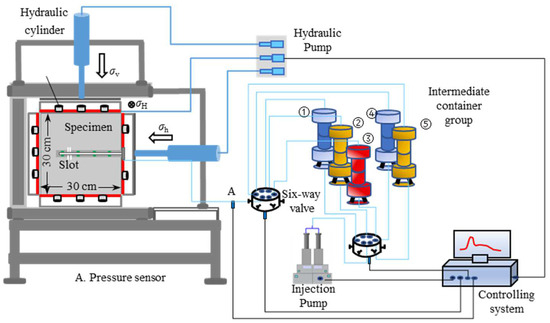
Figure 1.
Schematic diagram of the true triaxial fracturing physical simulation apparatus.
2.1.1. Control System
The control system primarily consists of a computer and fracturing system controlling software, serving two main functions. First, it controls the injection system and the true triaxial pressure system. By setting injection parameters and stress parameters in the fracturing simulation software, it manages the injection rate and the loading and control of triaxial pressure. Second, it provides data acquisition and recording functions, mainly used to record changes in wellhead pressure over the injection time during the fracturing process.
2.1.2. Injection System
The injection system mainly consists of an injection pump and various valves and pipelines. Its primary function is to provide pressure for injecting the fracturing fluid. This system can precisely control the injection rate of both fracturing and acid fluids. The main technical parameters are as follows: The maximum output pressure of the booster piston is 140 MPa, with a resolution of 0.05 MPa; the effective volume of the booster is 600 mL; the minimum injection rate is 1 mL/min, and the maximum injection rate is 200 mL/min.
2.1.3. Stress Loading System
The triaxial stress loading system consists mainly of a hydraulic servo pump and a hydraulic chamber. It provides confining pressure for large true triaxial physical models, simulating the triaxial stress environment of the formation, with independent pressure application in all three directions. In Figure 1, σH means the maximum horizontal stress, σh means the minimum horizontal stress, and σV means the vertical stress. The system can accommodate specimens with a maximum size of 500 mm × 500 mm × 500 mm, and the maximum load in each direction can reach 8000 kN. The system ensures uniform force distribution, with axial forces evenly transmitted to the specimen through connecting plates and force transfer plates. During loading, the central position of the specimen can be maintained through program control, effectively preventing eccentric loading and the generation of bending moments.
2.1.4. Multi-Channel Acid Alternating Injection System
The multi-channel acid alternating injection system comprises acid piston containers, connecting pipelines, valves, and a sophisticated valve control system. This setup allows for the alternating injection of up to five different acid solutions. By utilizing solenoid valves to manage the connection and disconnection of multiple intermediate containers, the system efficiently facilitates the alternating injection of various fluids.
2.2. Sample Preparation
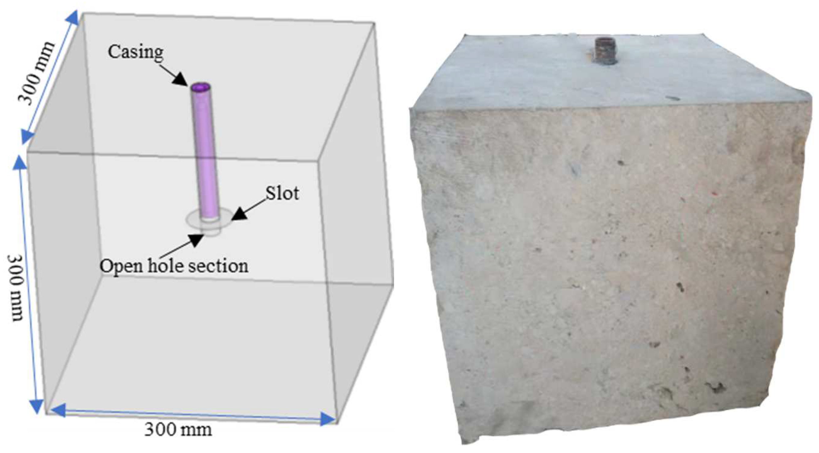
The dolomitic limestone outcrop of the Ma5 Member of the Majiagou Formation in Daniudi Gas Field, Ordos Basin, was used in the experiment. Natural fractures are developed in the outcrop, and almost all natural fractures are filled with cement. The mechanical properties of the outcrop matrix were tested with the triaxial rock mechanics comprehensive test system (TAW2000) manufactured by Changchun Chaoyang machinery works, Changchun, China. Under the confining pressure of 60 MPa, the average Young’s modulus is 38.3 GPa, the average Poisson’s ratio is 0.24, and the average compressive strength is 148.5 MPa. The tensile strength is 6.6 MPa. It is similar to the mechanical properties of the downhole core of the Majiagou Formation in the Daniudi gas field. The outcrop specimen was cut into a cubic sample with dimensions of 300 × 300 × 300 mm. To ensure uniform loading of triaxial stress on the specimen, the cutting error of the cube’s edge length must not exceed 2 mm. After forming the cubic specimen, a blind hole is drilled in the center of one face. The hole has a diameter of 28 mm and a depth of 250 mm. At a depth of 240 mm within the blind hole, an initial fracture with a cutting depth of 3 mm is created using a grooving tool. Once drilling is complete, the rock debris inside the hole is cleaned out and allowed to dry. A steel tube, 200 mm in length with an inner diameter of 9 mm and an outer diameter of 20 mm, is used as an artificial wellbore. One end of the tube is threaded internally, and this threaded end is inserted into the drilled hole in the specimen, facing outward. The artificial wellbore is fixed in place using epoxy resin adhesive, leaving a 50 mm open hole section at the bottom of the specimen, as shown in Figure 2.

Figure 2.
Schematic diagram of the structure of the fracturing sample (left) and the physical object (right).
2.3. Experimental Scheme
The experiment primarily considers the effects of different injection rates, types of fracturing fluids, injection methods, and natural fractures on the fracture propagation patterns during acid fracturing. Triaxial stress loading simulates the stress state of a horizontal well, with the direction parallel to the wellbore being the horizontal minimum principal stress (σh). The other two directions are the vertical stress (σV) and the horizontal maximum principal stress (σH), respectively. According to the in situ stress test results from the Daniudi gas field, the horizontal maximum principal stress ranges from 48 to 55 MPa, and the horizontal minimum principal stress ranges from 35 to 40 MPa, with a horizontal stress difference of 13 to 15 MPa. Since the main factor affecting fracture propagation and the interaction between artificial and natural fractures is the horizontal stress difference, and considering the limitations of the stress loading equipment, the experiment reduces the magnitude of the triaxial stresses based on the actual stress conditions. The vertical stress is set at 25 MPa, the horizontal maximum principal stress is set at 20 MPa, and the horizontal minimum principal stress is set at 5 MPa. The injection rates in the experiment are converted using similarity criteria. The field injection rates range from 6 to 12 m3/min, and in the experiment, the rates are set at 60 mL/min, 90 mL/min, and 120 mL/min to simulate field rates of 6 m3/min, 9 m3/min, and 12 m3/min, respectively. It should be noted that due to the limitations of laboratory equipment and sample size, these rate conversions can only partially reflect the impact of rate changes on fracture initiation and near-wellbore propagation. Fracturing fluid mainly includes high viscosity fracturing fluid, gelled acid, and crosslinked acid used in field fracturing. Since the experiments were conducted at room temperature, the viscosities of the fluids used were based on measurements of the field fracturing fluid viscosity at formation temperature. For instance, in the Majiagou Formation, the field fracturing fluid has a viscosity of approximately 100 mPa·s at formation temperature. In our experiments, the thickener concentration was adjusted to match the viscosity of the field fracturing fluid under formation conditions. The high-viscosity fracturing fluid was formulated with 0.6% polymer thickener BFC-200 and 1.2% crosslinker JX-JL-1, achieving a viscosity of up to 100 mPa·s at room temperature. The gelled acid is composed of 20% HCl and 0.7% thickener GDCH-1, with a viscosity of 40 mPa·s at room temperature. The crosslinked acid consists of 20% HCl, 0.8% thickener GDCH-2, and 0.7% crosslinker GDJL-1, with a viscosity of 70 mPa·s at room temperature. For Sample #6, the crosslinker content was increased to 1%, resulting in a viscosity of up to 100 mPa·s. A red dye was added to the fracturing and acid fluids to trace the fracture propagation paths during the acid fracturing process. The specific experimental scheme is detailed in Table 1.

Table 1.
Acid fracturing experiment scheme.
2.4. Experimental Procedures
The main experimental steps of the acid fracturing physical simulation experiment include stress loading of the samples, preparation of the fracturing fluid, fluid injection and fracturing, and comprehensive post-fracturing analysis. The key experimental stages are as follows.
(1) Sample Loading: Before installation, the samples need to be wrapped in plastic wrap to prevent the acid from damaging the experimental equipment after the samples are fractured. The wrapped samples are placed in the rock sample pressure chamber, where a hydraulic stress loading system is used to apply triaxial pressure simultaneously. Considering horizontal well fracturing, the σh direction is parallel to the wellbore, σV is perpendicular to the bedding plane, and σH is perpendicular to both of the aforementioned directions. The pressure is gradually increased in all three directions until the set values are reached.
(2) Fracturing Fluid Preparation: The high-viscosity fracturing fluid, gelled acid, and crosslinked acid are prepared according to the specified formulations and added to the alternating injection system. When using a single-fluid fracturing method, only one intermediate container is used. For alternating injection of multiple fluids, the fluids are placed in separate intermediate containers as needed. The intermediate containers containing the fracturing fluids are connected to the sample and the injection pump.
(3) Acid Fracturing: The corresponding valves are opened and the injection pump is started according to the experimental scheme. When the pressure reaches 1 MPa, the pump is stopped to hold the pressure and leaks are checked. If there is no pressure change within 3 min, the pump is restarted and the pressure is further increased. During this process, pressure and other relevant data are collected by the data acquisition system.
(4) Post-Fracturing Analysis: The experiment is finished when fracturing fluid seeps from the sample or when there is a sudden drop in pressure without significant recovery. At this point, the injection pump is turned off to release the pressure and the confining pressure system is shut down. The post-fracturing sample is then removed and cleaned and then a comprehensive analysis of the internal and external fracture conditions is conducted using pressure curves, dye distribution, rock sample sectioning, and laser scanning.
3. Results and Analysis
After the experiment, the fracture morphology, breakdown pressure, and fracture surface erosion patterns were used to evaluate the impact of fracturing fluid type, injection rate, and injection method on the propagation behavior of acid fractures. In the analysis below, blue and yellow lines are used to outline the fractures on the surface of the samples to aid in observing fracture morphology. The blue solid lines represent artificial fractures, the yellow solid lines indicate unopened natural fractures, and the yellow dashed lines represent opened natural fractures.
3.1. Effect of Fracturing Fluid Types
To study the influence of fracturing fluid type on the propagation of acid fracturing fractures, high-viscosity fracturing fluid (non-reactive fluid), gelled acid, and crosslinked acid were used to fracture Samples 1#, 2#, and 3#, respectively. In addition to differences in viscosity, these fluids also vary in their reactivity with the rock. All other experimental parameters were kept constant, with an injection rate of 120 mL/min for each test.
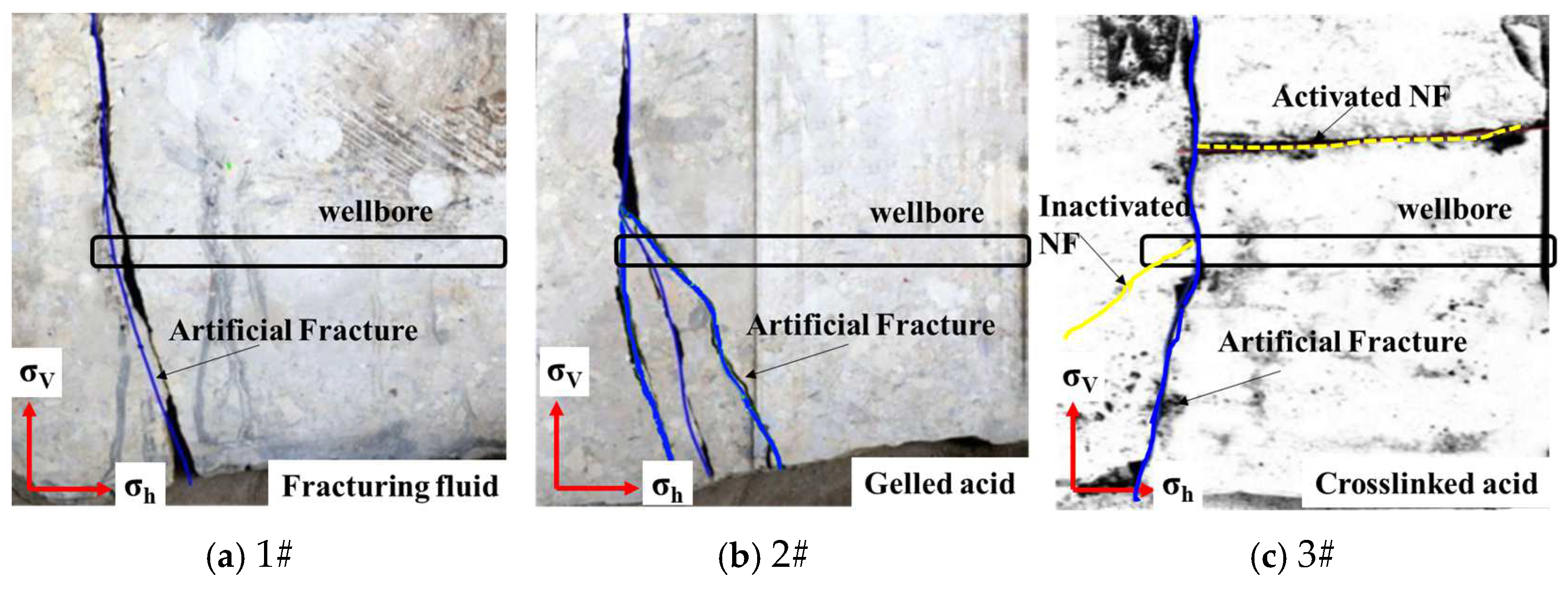
The fracture morphologies of the three samples after fracturing are shown in Figure 3. Since horizontal fracturing was simulated, all three samples developed transverse fractures perpendicular to the wellbore direction. The fractures initiated at the open hole section at the bottom of the wellbore and extended to the surface of the samples. The differences are as follows: Sample 1#, using high-viscosity non-reactive fluid, resulted in simple, straight double-wing cracks; Sample 2#, using gelled acid, exhibited more complex branching fractures due to the lower viscosity, higher leak-off capability, and faster acid–rock reaction rate of the gelled acid, which created multiple mechanical weak points in the open hole section, leading to the initiation of multiple fractures; and Sample 3#, using crosslinked acid for fracturing, resulted in relatively simple fractures. The crosslinked acid has a viscosity lower than the fracturing fluid but higher than the gelled acid, making its leak-off stronger than the fracturing fluid but weaker than the gelled acid. Its acid–rock reaction capability is also weaker than that of the gelled acid. Under these conditions, the fractures formed in Sample 3# were relatively simple. During the extension process, the fracture encountered a large-angle intersecting natural fracture, which was opened on one side due to acid leak-off and dissolution.

Figure 3.
Fracture morphology formed after the injection of different types of fracturing fluids: (a) a straight, double-wing crack formed in Sample 1# with high-viscosity non-reactive fluid; (b) multiple fractures were generated with gelled acid in Sample 2#; and (c) relatively simple fractures formed with crosslinked acid in Sample 3#.
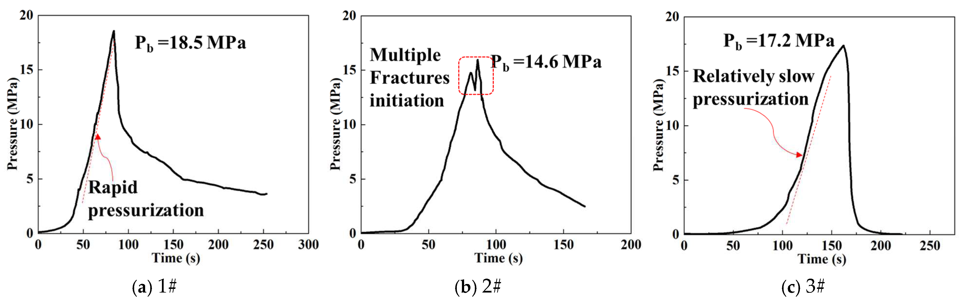
The variations in fracture morphologies resulting from different fluid properties are also evident in the pressure curves, as illustrated in Figure 4. Three distinct characteristics differentiate the pressure curves of the samples. Firstly, the most notable feature is that the breakdown pressure increases with the increase in viscosity. Sample 1#, which used the highest viscosity fracturing fluid, had the highest breakdown pressure at 18.5 MPa. Sample 2#, using gelled acid with the lowest viscosity of only 40 mPa, had a breakdown pressure of 14.6 MPa. Sample 3#, using crosslinked acid with intermediate viscosity, had a breakdown pressure of 17.2 MPa. The second characteristic difference is the rate of pressure increase at the wellhead before the samples fracture, as indicated by the red dashed lines in the figure. Sample 1#, having no reactivity and the highest viscosity, had the weakest leak-off performance, resulting in the fastest pressure increase. Sample 3#, with intermediate viscosity and reactivity, had a pressure increase rate second only to Sample 1#. Sample 2#, with the lowest viscosity and strongest reactivity, had the strongest leak-off capability, resulting in the slowest pressure increase. The final characteristic is the distinct differences in the shapes of the three curves. Sample 1# exhibits typical homogeneous rock hydraulic fracturing characteristics, with a sudden pressure drop after the bi-wing fractures extend to the boundary. Sample 2# shows two peaks after reaching the breakdown pressure, indicating the initiation of multiple fractures. The curve shape of Sample 3# is similar to that of Sample 1#, corresponding to their similar fracture morphologies.
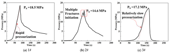
Figure 4.
Wellhead pressure change curves during fracturing with different types of fracturing fluids: (a) Sample 1# had the highest breakdown pressure at 18.5 MPa with the highest viscosity fracturing fluid; (b) Sample 2#, using gelled acid with the lowest viscosity, had a breakdown pressure of 14.6 MPa; (c) Sample 3#, using crosslinked acid with intermediate viscosity, had a breakdown pressure of 17.2 MPa.
3.2. Effect of Injection Rates
Injection rate is another important factor affecting fracture propagation. To study the influence of injection rate on acid fracturing crack propagation, Samples 3#, 4#, and 5# were fractured at rates of 120 mL/min, 90 mL/min, and 60 mL/min, respectively. In the Majiagou Formation, crosslinked acid is the primary acid system used to etch the fracture surface, as its higher viscosity, compared to gelled acid, allows for greater acid penetration. Thus, crosslinked acid was used as the fracturing fluid, and all other experimental parameters were kept constant.
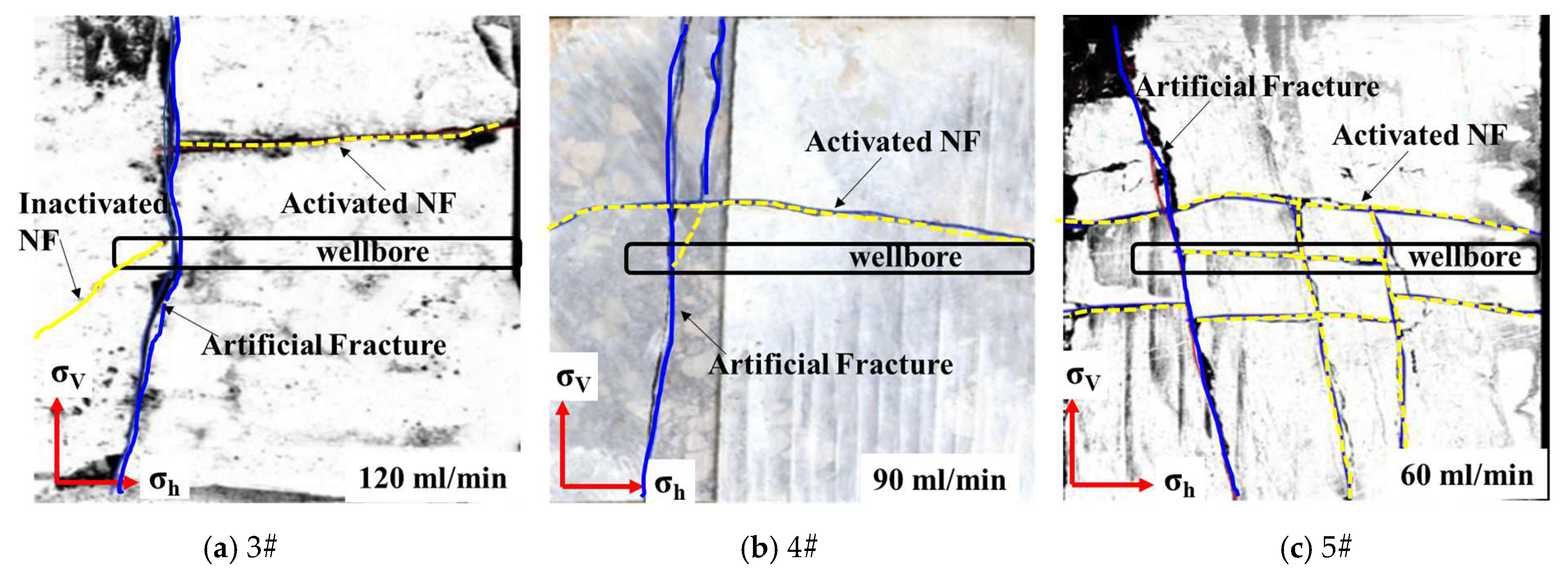
After acid fracturing at different injection rates, the fracture morphology shows significant differences, as illustrated in Figure 5. The primary difference is the change in fracture complexity due to the activation of natural fractures. At higher injection rates, the pressure rises quickly, and the acid fluid has a shorter leak-off time before the sample breaks, resulting in reduced leak-off volume. This leads to the acid having weaker dissolution and reaction effects. Natural fractures intersecting with the wellbore do not have sufficient time to dissolve before reaching the breakdown pressure. Once the fractures break through the boundary, the pressure within the fractures decreases, preventing the activation of natural fractures. As the injection rate decreases, the acid leak-off time and dissolution time increase along with the dissolution volume, creating multiple weak points within the wellbore and promoting the formation of multiple fractures. When the injection rate is reduced to 60 mL/min, a natural fracture develops along the wellbore and connects with other natural fractures, causing a large amount of acid to leak into the natural fracture network, ultimately forming an intricate fracture system.
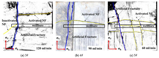
Figure 5.
Fracture morphologies formed after acid fracturing at different injection rates: (a) one NF was activated with an injection rate of 120 mL/min; (b) two NFs were activated with an injection rate of 90 mL/min; and (c) complex fracture network formed with an injection rate of 60 mL/min due to NF activation.
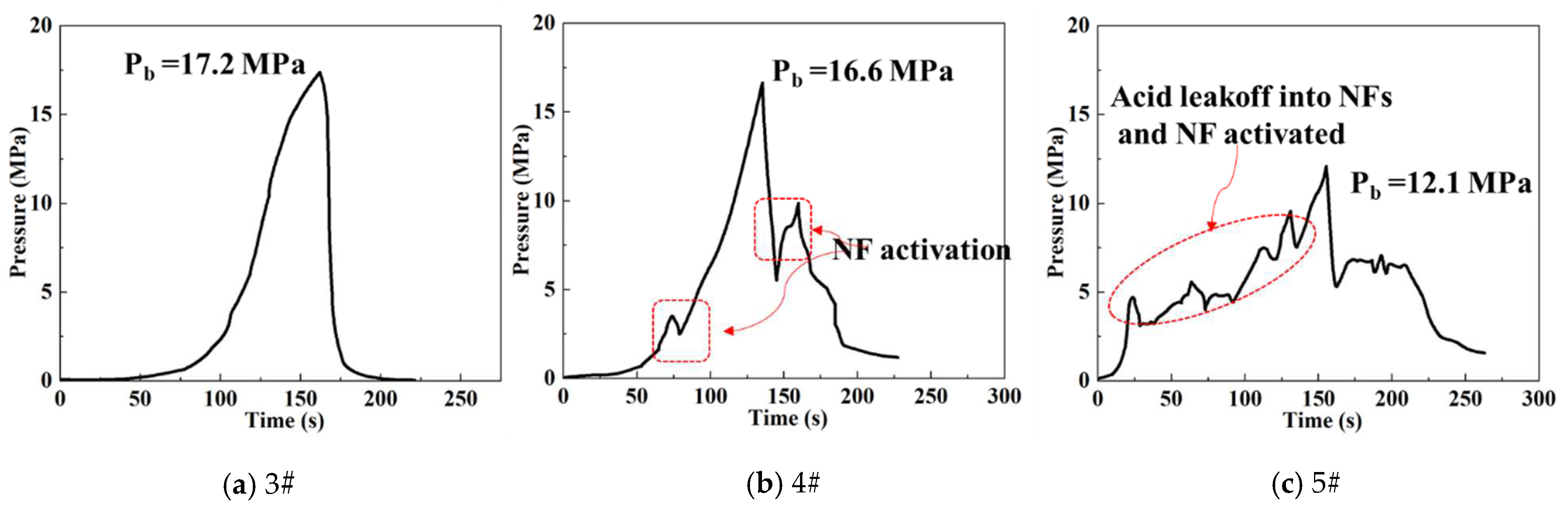
The differences in fracture morphology can be indirectly reflected in the pressure curves. The injection pressure curves for the three experiments at different injection rates are shown in Figure 6. A comparative analysis was conducted from three aspects: breakdown pressure, pressure increase rate, and curve fluctuations. As the injection rate increases, the breakdown pressure rises, and the pressure increase rate also significantly accelerates, both of which are related to acid leak-off and dissolution. Additionally, for Samples 4# and 5#, noticeable fluctuations in the pressure curve can be observed before and after breakdown. This is due to the partial activation of natural fractures after dissolution. These analytical results correspond to the observed fracture morphologies.

Figure 6.
Wellhead pressure variation curves during the acid fracturing process at different injection rates: (a) the highest breakdown pressure was observed among three samples with different injection rates; (b) intermediate breakdown pressure along with pressure fluctuations was observed when fractured with the intermediate injection rate; and (c) noticeable fluctuations in the pressure curve were recorded with the low injection rate.
3.3. Effect of Injection Method
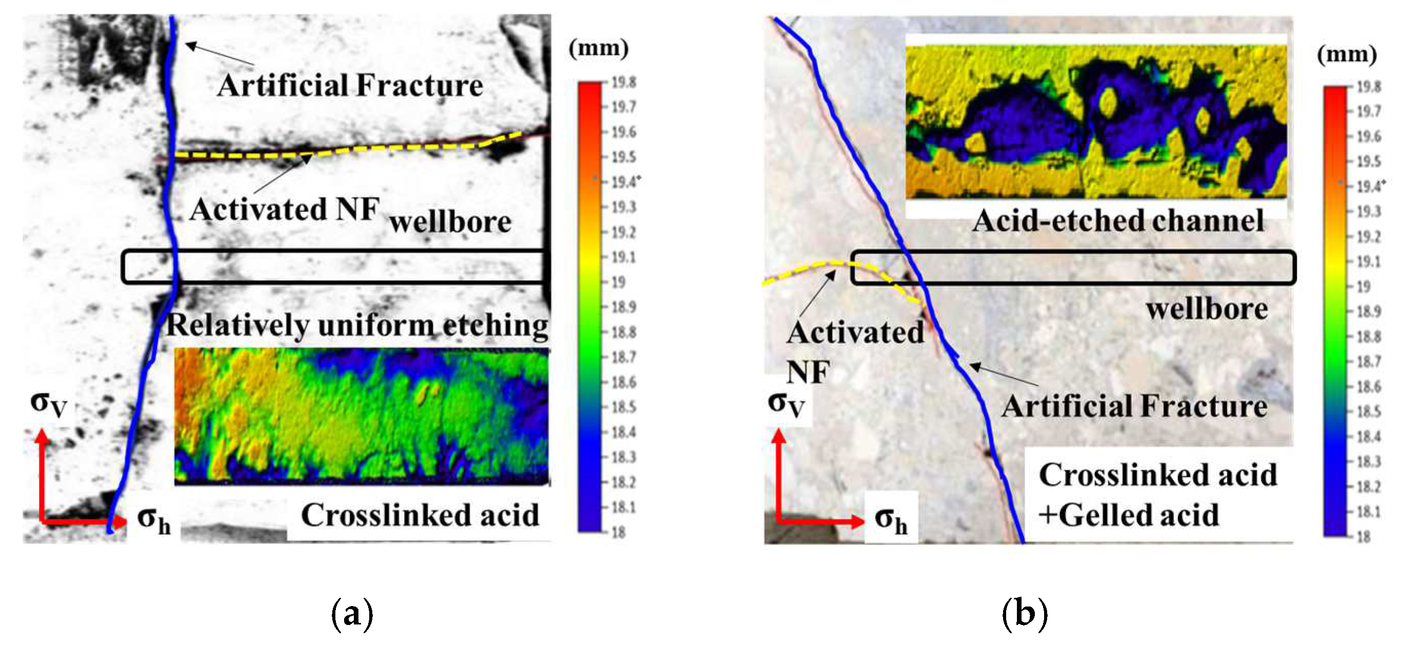
In acid fracturing, a multi-stage alternating injection of high- and low-viscosity fluids is often used to enhance the differential etching of the fracture surfaces. However, there has been limited research on its impact on fracture propagation patterns. In the experiment, Samples 7# and 3# were compared to study the effect of injection patterns on the morphology of acid fractures. After fracturing, both samples were cut open along the surface fractures, and a 3D laser profilometer was used to capture the dissolution morphology of the rock. Sample 3# underwent crosslinked acid fracturing, while Sample 7# used a combination of crosslinked acid and gelled acid fracturing with a volume ratio of 7:3. Acid was injected for an additional 10 min after the fractures reached the boundary to observe the etching patterns on the fracture surfaces. The post-fracturing morphology and surface etching patterns of the fractures in both samples are shown in Figure 7.

Figure 7.
Comparison of fracture morphology and surface etching morphology formed through single-acid hydraulic fracturing and multi-stage alternating injection fracturing: (a) fracture morphology and surface etching morphology formed through single-acid hydraulic fracturing. (b) fracture morphology and surface etching morphology formed through alternating injection fracturing.
Comparing the fracture morphologies formed by the two fracturing modes, the differences are minimal. Both consist of a transverse fracture perpendicular to the wellbore and a natural fracture intersecting the main fracture at a high angle. The rock samples were cut along the main fracture marked in blue, and a laser scanner was used to scan the local acid etching in representative areas, resulting in the color contour maps shown in the figure. In these maps, blue indicates deeper etched areas, while red represents raised areas. The contour map in Figure 7a shows that when a single crosslinked acid is injected, the etching is relatively uniform, with local pits that do not connect to form continuous channels. However, with alternating injection, the viscosity difference between the two acids causes the gelled acid to form connected grooves within the crosslinked acid. This increases the degree of non-uniform etching on the fracture surfaces. This fracturing method enhances the ability of acid-etched fractures to maintain conductivity under closure stress.
3.4. Effect of NFs
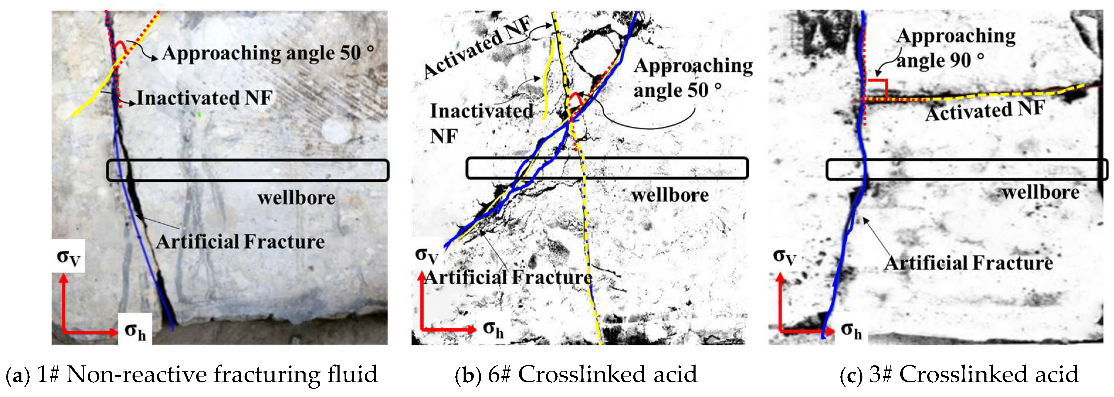
The above section analyzes the influence of engineering factors on acid fracturing crack propagation. Next, the influence of natural fractures on crack propagation under different injection conditions is analyzed from the aspect of geological factors. Samples 1# and 6# were selected to analyze the influence of different types of fracturing fluids on the interaction between natural and artificial fractures. Samples 6# and 3# were selected to compare the influence of natural fracture inclination angles on the interaction between artificial fractures and natural fractures. All three samples have a flow rate of 120 mL/min, with the other experimental parameters remaining constant.
In comparing Sample 1# and Sample 6#, both the artificial fractures (blue) and natural fractures (yellow) intersect at an angle of approximately 50 degrees, as shown in Figure 8a,b. In Sample 1#, the artificial fracture passes directly through the natural fracture without activating it. However, in Sample 6#, the artificial fracture passes through and activates the natural fracture. The role of acid in opening natural fractures is significant. Acid can infiltrate natural fractures through filtration, reducing the cementation strength within these fractures and making them more prone to activation. In contrast, non-reactive fracturing fluids do not have the same effect, making natural fractures less likely to open at high approach angles. Figure 8b,c compare the opening of natural fractures under the same acid solution but with different approach angles of the natural fractures. In Sample 3#, the artificial fracture intersects the natural fracture at an angle close to 90 degrees. The artificial fracture passes through the natural fracture and opens one side of it. This occurs because when the natural fracture is horizontally developed, it is subjected to vertical stress. Since the vertical stress is much greater than the minimum horizontal principal stress, the difficulty of opening the fracture increases.

Figure 8.
Impact of nature fractures on fracture propagation under different injection conditions: (a) and (b) compare the influence of different types of fracturing fluids on the interaction between natural and artificial fractures; (b,c) compare the influence of natural fracture inclination angles on the interaction between artificial fractures and natural fractures.
4. Discussion
Acid fracturing is an important technique for the stimulation of carbonate reservoirs. This is particularly true for tight fractured carbonate formations where maximizing the acid action distance and expanding the stimulated volume are critical for successful acid fracturing. The use of pre-pad fluid in acid fracturing can help reduce filtration loss of subsequent acid and lower the temperature within the fracture. However, because the pre-pad fluid is non-reactive, its activation effect on natural fractures is relatively weak, often resulting in the formation of a single dominant fracture in the open hole. Acid can weaken the mechanical properties of natural fractures in the open hole, creating multiple mechanical weak points. This can ultimately lead to the simultaneous initiation of multiple fractures within the wellbore, increasing the complexity of fractures in the near-wellbore area. Therefore, before acid fracturing, gelled acid can be used to pre-treat the open hole section, reducing the fracture pressure while also promoting the initiation of multiple fractures.
Elevating the pumping displacement results in a decrease in filtration time and an augmentation in the height and length of the primary fracture. The infiltration of acid into natural fractures fosters the weakening of their mechanical properties, which in turn aids in the activation of these fractures, thereby expanding the stimulation volume. Consequently, a strategy involving alternating injections of low-viscosity acid at lower displacement levels and high-viscosity acid at higher displacement levels should be employed to enhance the overall stimulation volume. Furthermore, the application of a multi-stage alternating injection technique during acid fracturing is advisable. This method not only mitigates filtration loss but also promotes non-uniform etching patterns on acid-etched fracture surfaces via viscous fingering, ultimately yielding improved flow conductivity maintenance capabilities.
5. Conclusions
In this paper, a series of large-scale acid fracturing physical simulation experiments were carried out using true triaxial acid fracturing equipment to study the influence of fracturing fluid types, injection displacements, injection methods, and natural fractures on the propagation laws of acid fracturing fractures. The main conclusions obtained are as follows:
(1) After fracturing with non-reactive fluid, the number of fracture initiations is lower; the acid can form multiple weaknesses in the wellbore through dissolution, which promotes the initiation of multiple cracks. Using low-viscosity acid as pre-treatment before fracturing can effectively improve the complexity of fractures near the well and improve the range of near-well stimulation.
(2) Under conditions of high displacement and high viscosity, the fracture morphology tends to be straightforward. In contrast, injecting acid at low viscosity and low displacement promotes the initiation and extension of natural fractures, thereby increasing the overall complexity of the fracture network.
(3) The multi-stage alternating injection method can reduce acid fluid loss while simultaneously increasing the degree of differential etching through viscous fingering. This approach enables acid-etched fractures to attain a high level of flow conductivity and effectively maintain that conductivity over time.
Author Contributions
Conceptualization, Y.Z. (Yongchun Zhang) and H.Z.; methodology, Y.Z. (Yongchun Zhang) and H.Z.; validation, Y.Z. (Yongchun Zhang), H.Z., Y.Z. (Ying Zhong) and J.K.; investigation, H.Z.; resources, Y.Z. (Yongchun Zhang); data curation, Y.Z. (Ying Zhong); writing—original draft preparation, Y.Z. (Yongchun Zhang); writing—review and editing, S.D.; visualization, J.K.; supervision, Y.Z. (Yongchun Zhang); project administration, Y.Z. (Yongchun Zhang). All authors have read and agreed to the published version of the manuscript.
Funding
This research was funded by The Basic Science Center Project of the National Natural Science Foundation of China, “Flow Regulation in Ultra-Deep Oil and Gas Drilling and Production” (Project No.: 52288101).
Data Availability Statement
The raw data supporting the conclusions of this article will be made available by the authors upon request.
Conflicts of Interest
Author Yongchun Zhang is employed by the company Sinopec North China Oil & Gas Company. The remaining authors declare that the research was conducted in the absence of any commercial or financial relationships that could be construed as a potential conflict of interest.
References
- Mou, J. Modeling Acid Transport and Non-Uniform Etching in a Stochastic Domain in Acid Fracturing; Texas A&M University: College Station, TX, USA, 2010. [Google Scholar]
- Mou, J. Principle of Acidizing Stimulation Technology; Petroleum Industry Press: Beijing, China, 2023. [Google Scholar]
- Zhang, X.; Zhang, S.; Mou, J. Numerical investigation of hydraulic fracture propagation behavior in vuggy, naturally fractured carbonate reservoir—A case study of shunbei oil field. Geoenergy Sci. Eng. 2024, 242, 213257. [Google Scholar] [CrossRef]
- Deng, J.; Hill, A.; Zhu, D. A theoretical study of acid-fracture conductivity under closure stress. SPE Prod. Oper. 2011, 26, 9–17. [Google Scholar] [CrossRef]
- Salimi, S.; Ghalambor, A.; Hayer, H. Insights Into the Process of Effectively Acidizing Naturally Fractured Reservoirs. In Proceedings of the SPE International Symposium and Exhibition on Formation Damage Control, Lafayette, LA, USA, 26–28 February 2014. SPE-168126-MS. [Google Scholar]
- Panga, M.; Ziauddin, M.; Balakotaiah, V. Two-scale continuum model for simulation of wormholes in carbonate acidization. AIChE J. 2010, 51, 3231–3248. [Google Scholar] [CrossRef]
- Taylor, K.; Nasr-El-Din, H. Laboratory evaluation of in-situ gelled acids for carbonate reservoirs. SPE J. 2003, 8, 426–434. [Google Scholar] [CrossRef]
- Ugursal, A.; Zhu, D.; Hill, A. Development of Acid Fracturing Model for Naturally Fractured Reservoirs. SPE Prod. Oper. 2019, 34, 735–748. [Google Scholar] [CrossRef]
- Gou, B.; Ma, H.; Liu, Z. Research progress and prospect of numerical modeling for acid fracturing of heterogeneous carbonate reservoirs. Nat. Gas Ind. 2019, 39, 87–98. [Google Scholar]
- Zeng, Q.; Li, T.; Bo, L. Effect of acid pre-treatment on hydraulic fracturing in heterogeneous porous media. Geoenergy Sci. Eng. 2025, 246, 213601. [Google Scholar] [CrossRef]
- Budong, G.; Jianye, M.; Panpan, L. Numerical investigation into the acid flow and reaction behavior in the tight, naturally fractured carbonate reservoir during acid fracturing. Phys. Fluids 2024, 36, 113614. [Google Scholar]
- Guo, J.; Bo, G.; Dengyun, L. Advance and prospect of acid fracturing in deep carbonate reservoirs. Drill. Prod. Technol. 2024, 47, 121–129. [Google Scholar]
- Zheng, H.; Liao, R.; Cheng, N. Study of mechano-chemical effects on the morphology of hydraulic fractures. J. Pet. Sci. Eng. 2021, 206, 109031. [Google Scholar] [CrossRef]
- Li, C.; Wang, Y.; Deng, P. Influences of gelled acid on mechanical properties of the ordovician carbonate rocks in block shunbei, Tahe oilfield. Xinjiang Pet. Geol. 2018, 39, 689–695. [Google Scholar]
- Guo, J.; Ren, J.; Wang, S. Numerical simulation and application of multi-field coupling of acid fracturing in farctured tight carbonate reservoirs. Acta Pet. Sin. 2020, 41, 1219–1228. [Google Scholar]
- Aljawad, M.; Schwalbert, M.; Mahmoud, M. Impacts of natural fractures on acid fracture design: A modeling study. Energy Rep. 2020, 6, 1073–1082. [Google Scholar] [CrossRef]
- Gou, B.; Zhan, L.; Guo, J. Effect of different types of stimulation fluids on fracture propagation behavior in naturally fractured carbonate rock through CT scan. J. Pet. Sci. Eng. 2021, 201, 108529. [Google Scholar] [CrossRef]
- Wang, Y.; Hou, B.; Zhang, K. Laboratory true triaxial acid fracturing experiments for carbonate reservoirs. Pet. Sci. Bull. 2020, 3, 412–419. [Google Scholar]
- Mohtarami, E.; Baghbanan, A.; Eftekhari, M. Investigating of chemical effects on rock fracturing using extended finite element method. Theor. Appl. Fract. Mech. 2017, 89, 110–126. [Google Scholar] [CrossRef]
- Zhang, N.; Chen, X.; Luo, Z. Experimental study of fracture conductivity in dolomite reservoirs treated with different acid fracturing technologies. Geoenergy Sci. Eng. 2023, 227, 211914. [Google Scholar] [CrossRef]
- Hou, B.; Zhang, R.; Chen, M. Investigation on acid fracturing treatment in limestone formation based on true tri-axial experiment. Fuel 2019, 235, 473–484. [Google Scholar] [CrossRef]
- Zhang, K.; Chen, M.; Zhou, C. Study of alternating acid fracturing treatment in carbonate formation based on true tri-axial experiment. J. Pet. Sci. Eng. 2020, 192, 107268. [Google Scholar] [CrossRef]
- Su, X.; Qi, N.; Lu, Y. Experimental study on acid etching mechanism of acid fracturing in carbonate reservoirs. Geoenergy Sci. Eng. 2024, 241, 213079. [Google Scholar] [CrossRef]

Disclaimer/Publisher’s Note: The statements, opinions and data contained in all publications are solely those of the individual author(s) and contributor(s) and not of MDPI and/or the editor(s). MDPI and/or the editor(s) disclaim responsibility for any injury to people or property resulting from any ideas, methods, instructions or products referred to in the content. |
© 2025 by the authors. Licensee MDPI, Basel, Switzerland. This article is an open access article distributed under the terms and conditions of the Creative Commons Attribution (CC BY) license (https://creativecommons.org/licenses/by/4.0/).