Article

The Effect of Activated Carbon Support on Ru/AC Catalysts Used for the Catalytic Decomposition of Hydroxylamine Nitrate and Hydrazine Nitrate

1
Department of Radiochemistry, China Institute of Atomic Energy, China National Nuclear Corporation, Beijing 102413, China
2
The 404 Company Limited, China National Nuclear Corporation, Lanzhou 732850, China
*
Authors to whom correspondence should be addressed.
Processes 2025, 13(3), 641; https://doi.org/10.3390/pr13030641
Submission received: 13 January 2025 / Revised: 12 February 2025 / Accepted: 21 February 2025 / Published: 24 February 2025
(This article belongs to the Section Catalysis Enhanced Processes)

Abstract

:
Hydroxylamine nitrate (HAN) and hydrazine nitrate (HN) are commonly found in radioactive waste solutions in nuclear fuel reprocessing, and their efficient removal is essential for waste treatment processes. In this study, six activated carbon carriers were selected to prepare Ru/AC catalysts for the simultaneous catalytic decomposition of HAN and HN, with the aim of exploring the effect of carrier properties on catalytic performance. The catalyst’s activity was evaluated in a batch reaction unit, and its structural properties were characterized using N2 physical adsorption, XRD, SEM, and TEM techniques. The results revealed that the catalyst’s activity was primarily determined by the carrier’s particle size and specific surface area. Additionally, corrosion-induced damage to the pore structure and Ru loss were identified as the main factors responsible for catalyst deactivation. This study highlights the importance of optimizing carrier structure to enhance the activity and stability of Ru/AC catalysts.

1. Introduction

Over the course of several decades of development, the PUREX process has emerged as the sole nuclear fuel reprocessing process currently in commercial operation globally [1,2]. Within the PUREX process, a reducing agent is introduced to reduce the Pu(IV) present in the organic phase into Pu(III). Significantly, Pu(III) exhibits a non-extractable characteristic under these conditions. Consequently, Pu(III) migrates into the aqueous phase, thereby enabling the effective separation of uranium from plutonium [3,4]. Currently, in nuclear reprocessing plants, hydroxylamine nitrate and hydrazine nitrate are commonly employed as reducing agents [5,6]. During the entire reduction procedure, a large amount of medium-level radioactive waste is generated, which contains hydroxylamine nitrate (HAN, 0.3 mol/L), hydrazine nitrate (HN, 0.1 mol/L), and nitric acid (0.6–1.8 mol/L) [7]. For the purpose of minimizing the volume of radioactive waste liquid, it is necessary for medium-level radioactive waste liquids to be subjected to evaporative concentration and denitration treatment. However, the presence of hydroxylamine nitrate and hydrazine nitrate in the nitric acid waste solution will adversely impact subsequent evaporation denitration treatment [8,9]. During the evaporative concentration and chemical denitration stages, issues like excessive radioactivity in the condensate and a pronounced risk of explosion may occur [10,11,12,13,14]. Consequently, it is of utmost necessity to remove hydroxylamine nitrate and hydrazine nitrate from the nitric acid waste solution [15].
Currently, a commonly employed approach for their removal involves introducing an oxidant (such as sodium nitrite or nitrogen dioxide) [10,11]. Adding sodium nitrite will introduce sodium salts into the system, generating a large amount of α-waste. This increases the complexity of subsequent waste liquid concentration, treatment, and disposal processes. While introducing excess nitrogen oxides can mitigate the salt introduction issue from sodium nitrite and effectively decompose the reductant, there are still areas for improvement [16,17,18]. Nitrogen dioxide is a component of highly corrosive substances, and its storage and flow control present challenges. It also poses potential health risks to operators. Excess nitrogen dioxide places additional demands on the exhaust gas emission purification system. Nitrogen dioxide is produced via the reaction of concentrated nitric acid with sodium nitrite inside a specialized column designed for nitrogen oxide preparation. The preparation of nitrogen dioxide results in a significant amount of highly acidic and salt-containing waste liquid [19,20]. The utilization of supported noble metal catalysts for the catalytic decomposition of hydroxylamine nitrate and hydrazine nitrate represents a novel, safe, and environmentally friendly method of removal. This method offers several advantages over traditional ones: (1) The equipment system features a simple composition, which streamlines nitrogen oxide preparation and transportation systems. (2) The overall process operation is extremely convenient, only requiring the control of the feed liquid flow rate and temperature. (3) During the entire treatment process, there is no need to introduce chemical reagents, thereby eliminating the use of nitrogen oxides. This greatly reduces the maintenance and repair costs caused by the strong corrosiveness of nitrogen oxides. (4) The amounts of waste liquid and waste gas are significantly reduced. This reduction includes both the tail gas generated from the excessive introduction of nitrogen oxides and the high-acid and salt-containing waste liquid produced during the nitrogen oxide preparation process [21,22,23,24]. Therefore, this method has great application prospects in the reprocessing procedure. Activated carbon possesses abundant pore structure, an exceptionally large specific surface area, excellent acid–alkali resistance, and is cost-effective and readily available, making it an ideal catalyst support. In contrast to catalysts composed of other noble metals, Ru-based catalysts not only showcase a more advantageous cost-performance ratio but also reveal a higher degree of catalytic activity [25,26,27,28]. Therefore, in this study, we employed activated carbon as the carrier material with Ru as the active component to synthesize the Ru/AC catalyst.
The structural properties of activated carbon significantly influence the activity of Ru/AC catalysts, and activated carbon exhibits facile modifiability. Feng et al. investigated the adsorption properties of activated carbon fibers (ACFs) with varying pore structures and specific surface areas on H2S [29]. Their findings revealed that ACFs possessing larger surface areas exhibited enhanced adsorption and retention capacities for sulfur, while thermal treatment further augmented these capabilities. Rey et al. investigated the decomposition of hydrogen peroxide using three types of activated carbon and found that a lower degree of order in the carbon structure and fewer developed graphene layers resulted in higher decomposition rates [30]. Kowalczyk et al. conducted a pre-calcination treatment of activated carbon at a temperature of 1900 °C in a helium atmosphere and prepared Ru/AC catalysts using RuCl3·0.5H2O and Ru3(CO)12 as precursors through the impregnation method [31]. Their results demonstrated that the activity of the Ru catalyst supported on pre-calcined activated carbon was significantly superior to that supported on untreated activated carbon. There are various methods to modify the surface and structure of carbon supports. In terms of preparation, biomass materials such as peanut shells and waste wood can be pyrolyzed. Activation methods include physical activation (using steam or CO2) and chemical activation (using KOH or H3PO4). Surface modification methods involve oxidation (using HNO3 or H2O2), reduction, and metal loading. Additionally, activated carbon can also be prepared from biochar [32,33,34,35,36,37,38,39,40,41,42,43,44,45,46]. Therefore, it is imperative to identify the factors that impact catalyst activity to discover suitable modification strategies.
In this study, six commercially available activated carbons sourced from distinct manufacturers were carefully selected. They were then utilized to prepare corresponding Ru/AC catalysts through the impregnation method. Afterward, the catalytic activity of these catalysts was meticulously evaluated. Their characterization comprehensively involved N2 physical adsorption, XRD, SEM, and TEM techniques. The findings clearly revealed that the particle size and specific surface area of the activated carbon were key factors in determining the catalyst’s activity. Moreover, it was determined that corrosion-induced damage to the pore structure of the activated carbon, along with Ru loss, was pinpointed as the primary cause of catalyst deactivation. These results provide valuable insights for future catalyst design and improvement.

2. Experimental Section

2.1. Material and Regents

Hydroxylamine nitrate (AR grade, 50 wt%) was purchased from Beijing Aerospace Kane New Materials Co., Ltd., Beijing, China. Hydrazine hydrate (AR grade, 85 wt%) and nitric acid (AR grade, 69 wt%) were purchased from Sinopharm Chemical Regent Co., Ltd., Beijing, China. Hydrazine nitrate was prepared via the neutralization reaction between hydrazine hydrate and nitric acid. RuCl3·xH2O (AR grade, with 37.5–41 wt% Ru content) was purchased from Titan Scientific Co., Ltd., Shanghai, China. As for activated carbon samples, AC1 (10–20 mesh) was sourced from Henan Tonghui Activated Carbon Co., Ltd., Zhengzhou, China. AC2 (10–20 mesh) was acquired from Gongyi Luanhua Purification Materials Co., Ltd., Gongyi, China. AC3 (10–20 mesh) was purchased from Beijing Beike Honghua Environmental Protection Technology Co., Ltd., Beijing, China. AC4 (4–8 mesh) was obtained from Shijiazhuang Hongsen Activated Carbon Co., Ltd., Shijiazhuang, China. AC5 (4–8 mesh) was procured from Jiangsu Xinhua Activated Carbon Co., Ltd., Liyang, China. AC6 (4–8 mesh) was bought from Chengde Northern Activated Carbon Co., Ltd., Chengde, China. Tributyl phosphate (AR grade) was obtained from Shanghai Macklin Biochemical Technology Co., Ltd., Shanghai, China. Kerosene (AR grade) was sourced from Sinopharm Chemical Reagent Co., Ltd., Beijing, China.

2.2. Preparation of Ru/AC Catalysts

The Ru/AC catalysts were prepared using the initial wet impregnation method. First, the activated carbon was thoroughly rinsed multiple times with deionized water. The rinsing process continued until the supernatant solution turned clear. Subsequently, the activated carbon was dried and stored for further use.
To prepare the impregnation solution, 1.35 g of RuCl3·xH2O was dissolved in 15 mL of deionized water. This solution was then carefully added to 10 g of the pre-treated activated carbon. The resulting mixture was left to undergo adsorption at ambient temperature for a duration of 24 h.
After the adsorption step, the solvent was completely removed by evaporation at a temperature of 120 °C. Next, the impregnated catalyst underwent a two-step heat treatment process. It was first calcined under a nitrogen atmosphere at 400 °C for 1 h. Following this, the catalyst was treated with hydrogen at the same temperature (400 °C) for 10 h. Through these processes, the Ru/AC catalysts were successfully prepared.
When different types of activated carbon (AC1 to AC6) were used as carriers, the corresponding catalysts were labeled as Ru/AC1 to Ru/AC6, respectively.

2.3. Characterization of the Catalysts

The specific surface areas of the synthesized materials were measured via N2 physical adsorption at 77 K. Prior to measurement, the samples were degassed using a Micromeritics Model ASAP 2010 apparatus. (purchased from Micromeritics Instrument Corporation, Norcross, GA, USA). The BET method was utilized to measure the specific surface area of the sample, while the BJH model was applied to calculate the pore distribution results. X-ray diffraction (XRD, Rigaku MiniFlex 600 Cu Kα purchased from Rigaku Corporation, Tokyo, Japan) was obtained to characterize the crystal structure of Ru. The X-ray tube voltage was set at 40 kV, with a tube current of 30 mA, and the scanning range spanned from 2θ = 10° to 90°. The morphology of activated carbon and Ru/AC catalysts was visualized using a scanning electron microscope (SEM, PHENOM G2 purchased from Phenom–World B.V., Eindhoven, The Netherlands) and a transmission electron microscope (TEM, JEM–F200 purchased from JEOL Ltd., Tokyo, Japan) after the materials were pulverized into powders finer than 200 mesh. Inductively coupled plasma atomic emission spectroscopy (ICP–AES, iCAP6000 purchased from Thermo Fisher Scientific, Waltham, MA, USA) was utilized to determine the real content of Ru in the catalysts. We also used an ultraviolet–visible spectrophotometer (UV, PerkinElmer Lambda 950, procured from PerkinElmer, Inc., Waltham, MA, USA).

2.4. HAN and HN Concentrations Analysis

The concentrations of HAN and HN were measured via ultraviolet–visible spectrophotometry.
In solutions, HAN has the capacity to efficiently reduce Fe3+ ions to Fe2+ ions. When the pH is in the range of 2–9, o-phenanthrene reacts with Fe2+ ions to produce a color change. This reaction is highly selective and forms an extremely stable orange-red complex. The complex shows maximum absorption at 510 nm. Leveraging this color reaction, trace amounts of HAN can be precisely quantified through spectrophotometric analysis.
Under acidic conditions, HN reacts with p-dimethylaminobenzaldehyde to cause a color change. The absorbance of the resulting solution is measured at 457 nm. Within a certain range, the concentration of hydrazine is directly proportional to the measured absorbance. This proportional relationship allows for the accurate determination of its concentration.

2.5. Activity Evaluation of the Catalysts

The catalytic decomposition reaction of HAN and HN in HNO3 was conducted using a batch-type reaction apparatus. With a solid-to-liquid ratio set at 1:20, 1 g of the synthesized catalyst (on a dry-weight basis) and 20 mL of the feed solution (containing 0.3 mol/L HAN, 0.1 mol/L HN, and 1 mol/L HNO3, balanced with 30% v/v TBP/OK) were introduced into a round-bottom flask fitted with a condensation reflux system. Then, the flask was placed in a water bath, which was heated to 80 °C while stirring at a rate ranging from 200 to 300 r/min. (The impact of stirring speed on the experimental outcomes is negligible within the range of 200 to 400 revolutions per minute).
The duration of the reaction was noted. Once the reaction concluded, the catalyst was separated from the reaction mixture via straightforward filtration and directly utilized again in the model reaction for the next cycle.
Experimental observations show that the rate of bubble formation gradually declines. Towards the end of the reaction, there is a sudden sharp increase in bubble generation, which is attributed to the self-catalysis of hydroxylamine nitrate. At this point, the measured liquid contains concentrations of both hydroxylamine nitrate and hydrazine nitrate lower than 10−4 mol/L, suggesting that these compounds have decomposed completely.

3. Results and Discussion

3.1. N2 Physical Adsorption

The physical structural characteristics of the catalysts were measured via the N2 physical adsorption technique at 77 K. Figure 1 illustrates the adsorption–desorption isotherms and pore size distribution curves for both AC1 and AC4. As depicted in Figure 1a, both activated carbons exhibit similar adsorption–desorption isotherms. At relative pressures (P/P0) below 0.1, there is a sharp increase in the adsorption volume, followed by a plateau. This behavior corresponds to a typical Type I isotherm, indicating that the activated carbons are rich in micropores. The steep initial increase is attributed to the strong interaction between nitrogen molecules and the walls of micropores, which dominate the structure of the activated carbon samples. At higher relative pressures (P/P0 > 0.4), narrow hysteresis loops emerge in the adsorption–desorption isotherms, which is a characteristic feature of Type IV isotherms. This phenomenon suggests the presence of mesopores in the activated carbon structure, which is further supported by the pore size distribution analysis. As shown in Figure 1b, the pore size distribution curves for both AC1 and AC4 reveal that the majority of pores fall within the range of 0 to 5 nm, confirming the coexistence of micropores and mesopores in the samples. Specifically, the sharp peak in the pore diameter range below 2 nm is indicative of a substantial number of micropores, while the broader distribution extending beyond 2 nm suggests the presence of mesopores. This dual-porosity structure contributes to the enhanced accessibility and diffusion of reactants and products, which is beneficial for catalytic applications.
Additionally, it can be observed that AC1 exhibits a slightly larger adsorption volume compared to AC4, indicating a higher specific surface area and micropore volume. This difference in physical structure may influence the catalytic performance of Ru/AC catalysts, as larger specific surface areas provide more active sites for the dispersion of Ru and for catalytic reactions to occur.
The BET-specific surface area, pore volume, and pore size of the activated carbons, fresh catalysts, and used catalysts are presented in Table 1. The data reveal that there are minimal changes in pore size during both the preparation and utilization of the catalyst. This stability in pore size indicates that the overall pore structure remains largely intact, with changes primarily occurring in the micropore accessibility and pore connectivity.
In comparison to the original activated carbon, the Ru/AC catalysts show a significant reduction in specific surface area and pore volume. This reduction can be attributed to the following factors: dispersion of Ru particles within the activated carbon pores: (1) the deposition of Ru nanoparticles during the impregnation process leads to partial blockage of micropores and mesopores, thereby reducing the accessible surface area and pore volume; (2) high-temperature reduction: the reduction treatment at 400 °C under a hydrogen atmosphere may remove impurities such as sulfur (S), chlorine (Cl), nitrogen (N), and oxygen (O) that are present in the pore structure of activated carbon, resulting in a cleaner pore network but also contributing to a slight loss of microporosity; (3) structural damage due to high-temperature treatment: the thermal treatment during catalyst preparation can damage the delicate micropore structure of the activated carbon, leading to a decrease in the number of micropores and, consequently, a reduction in specific surface area and pore volume.
The used Ru/AC catalysts exhibit a further decrease in specific surface area and pore volume compared to the fresh catalysts. This degradation can be primarily attributed to (1) mechanical wear: the repeated handling and stirring of the catalyst during the reaction process may cause physical abrasion and fragmentation, leading to a reduction in the accessible pore structure; (2) corrosion by nitric acid: exposure of the catalyst to the acidic environment during the catalytic decomposition of hydroxylamine nitrate and hydrazine nitrate contributes to the corrosion of the activated carbon support, and this corrosion can lead to the collapse of micropores and mesopores, thereby diminishing the structural integrity of the support.
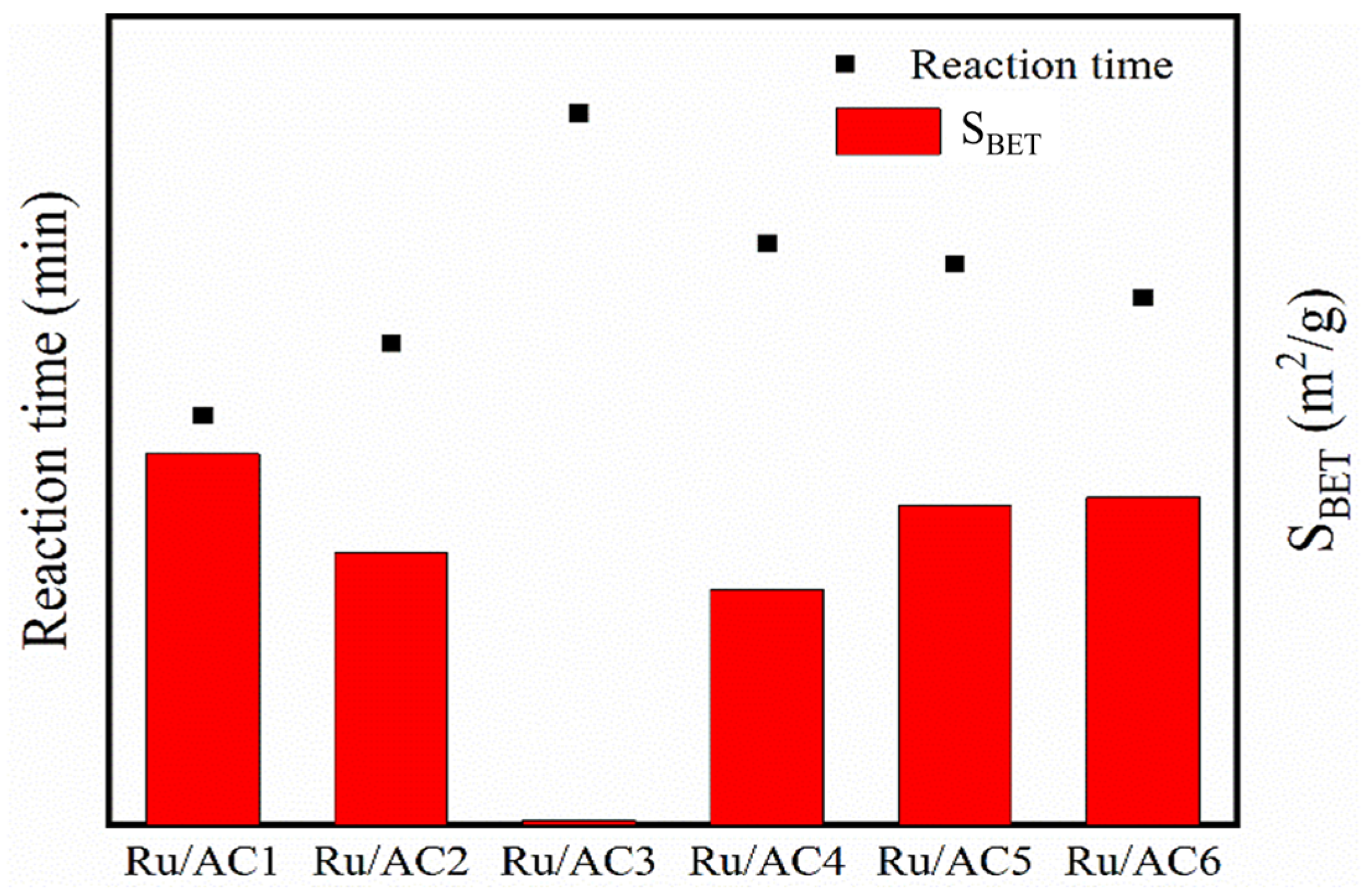
The activity of six Ru/AC catalysts was evaluated in a batch reaction unit under the conditions of 80 °C, a 1 g catalyst, and a 20 mL liquid feed (1 mol/L HNO3, 0.3 mol/L HAN, 0.1 mol/L HN). The comparative results, including the specific surface area (SBET) and reaction times, are illustrated in Figure 2. The particle size of the catalysts varies between two groups: Ru/AC1, Ru/AC2, and Ru/AC3 with a particle size of 10–20 mesh, and Ru/AC4, Ru/AC5, and Ru/AC6 with a particle size of 4–8 mesh. Despite the higher specific surface areas of Ru/AC5 and Ru/AC6 compared to Ru/AC2, their reaction times are significantly longer. This observation highlights the crucial role of particle size in determining catalyst activity. Larger particle sizes, as seen in Ru/AC4, Ru/AC5, and Ru/AC6, result in longer internal and external diffusion paths during the catalytic process. This increased diffusion resistance slows the mass transfer of reactants and products, ultimately reducing reaction rates. The catalytic mass transfer process involves five major steps: (1) the internal diffusion of reactants within the pores of the catalyst; (2) the adsorption of reactants onto the active sites; (3) chemical reactions at the active sites; (4) the desorption of reaction products from the active sites; and (5) the external diffusion of products away from the catalyst surface. Larger particles significantly prolong both internal and external diffusion times, which negatively impact overall reaction efficiency. Therefore, reducing particle size can enhance catalyst performance by minimizing diffusion resistance and improving mass transfer efficiency.
For catalysts with similar particle sizes (e.g., Ru/AC1, Ru/AC2, and Ru/AC3), there exists a positive correlation between catalytic activity and specific surface area. Catalysts with higher specific surface areas, such as Ru/AC1, demonstrate significantly reduced reaction times and enhanced activity in comparison to those with lower specific surface areas, aligning with findings reported in the literature [47]. This is because a larger specific surface area provides more active sites for the decomposition of hydroxylamine nitrate and hydrazine nitrate, thereby accelerating the reaction.
The results suggest that both particle size and specific surface area contribute to catalyst activity. While a larger specific surface area enhances the availability of active sites, smaller particle sizes facilitate more efficient mass transfer, enabling reactants and products to interact with active sites more effectively. Therefore, optimizing both parameters is critical to achieving superior catalytic performance.

3.2. XRD

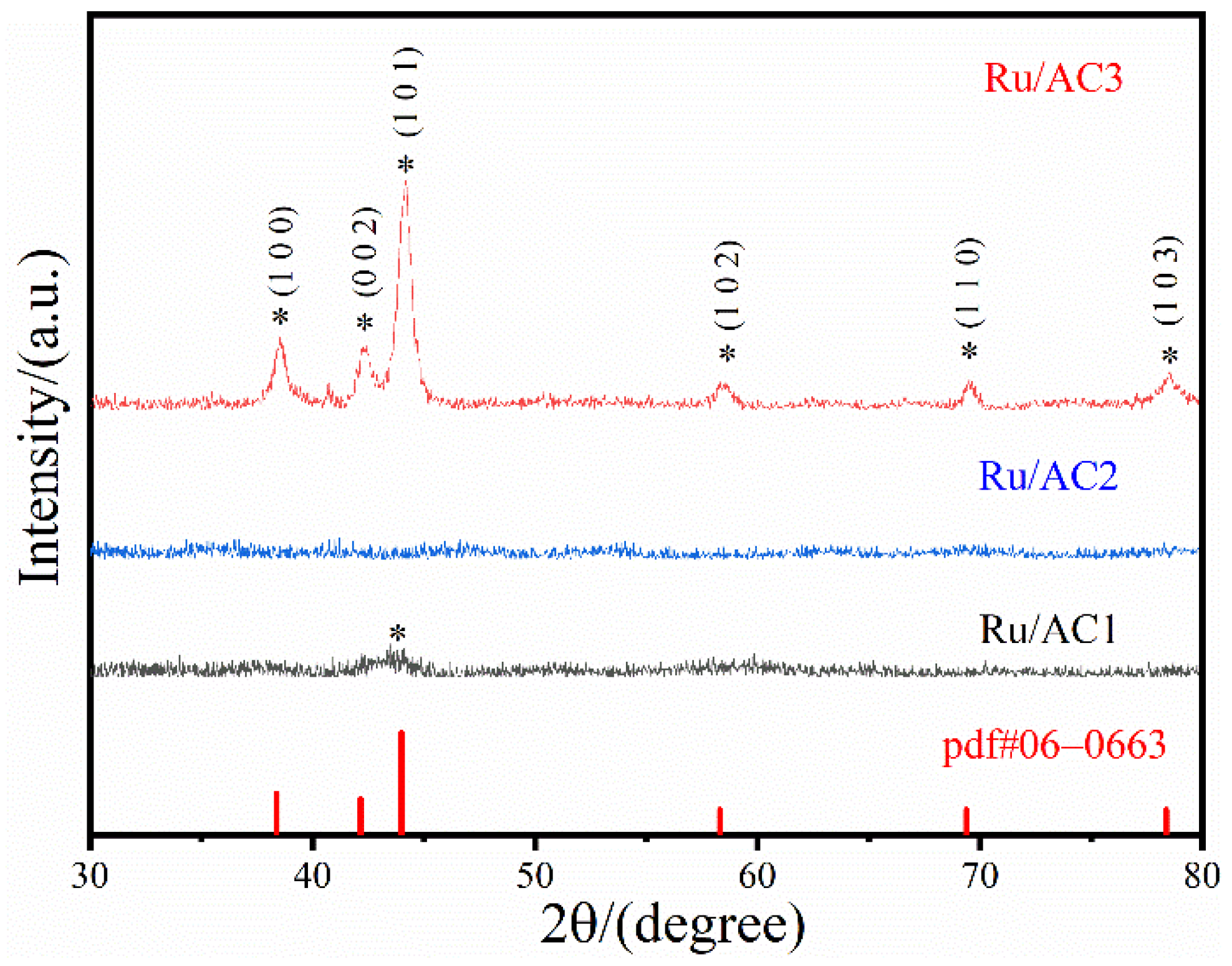
Ru/AC1, Ru/AC2, and Ru/AC3 showed significant differences in specific surface area and catalyst activity. To investigate the impact of catalyst surface area on catalytic activity, X-ray diffraction (XRD) analysis was conducted, as shown in Figure 3, and the results revealed significant differences in the crystallinity and dispersion of Ru species among the Ru/AC catalysts. The XRD spectra of Ru/AC3, which has a very small BET-specific surface area, exhibit distinct diffraction peaks at 2θ values of 38.6°, 42.7°, 44.2°, 58.4°, and 69.5°, corresponding to the crystal planes (100), (002), (101), (102), and (110) of metallic Ru species. The sharp and intense peaks indicate that Ru particles on Ru/AC3 are highly crystalline and relatively large, with low dispersion. This limited dispersion is attributed to the low specific surface area of AC3, which provides fewer active sites for Ru anchoring and catalysis, ultimately reducing its catalytic activity compared to Ru/AC1 and Ru/AC2.
As shown in Figure 3, in contrast, no characteristic diffraction peaks of Ru were observed in the XRD patterns of Ru/AC1 and Ru/AC2, suggesting that Ru particles are extremely small and highly dispersed on these catalysts. The higher BET-specific surface areas and well-developed pore structures of AC1 and AC2 facilitate the uniform dispersion of Ru nanoparticles, resulting in a larger number of active sites. This superior dispersion and reduced Ru particle size significantly enhance the catalytic performance of Ru/AC1 and Ru/AC2 compared to Ru/AC3. The results underscore the critical role of activated carbon structure in determining the dispersion and crystallinity of Ru species, with higher specific surface area and greater porosity leading to better dispersion and improved catalytic activity.
The XRD findings in Figure 3 strongly correlate with the catalytic performance results, confirming the importance of structural optimization of activated carbon supports. Supports like AC1 and AC2, with their high specific surface area and developed porosity, enable efficient dispersion of Ru nanoparticles, yielding highly active catalysts [48]. On the other hand, AC3’s limited surface area restricts Ru dispersion, resulting in larger particles with reduced catalytic activity. These insights highlight that tailoring the structural properties of activated carbon is essential for designing Ru/AC catalysts with high activity and stability.

3.3. Recyclability of the Catalyst

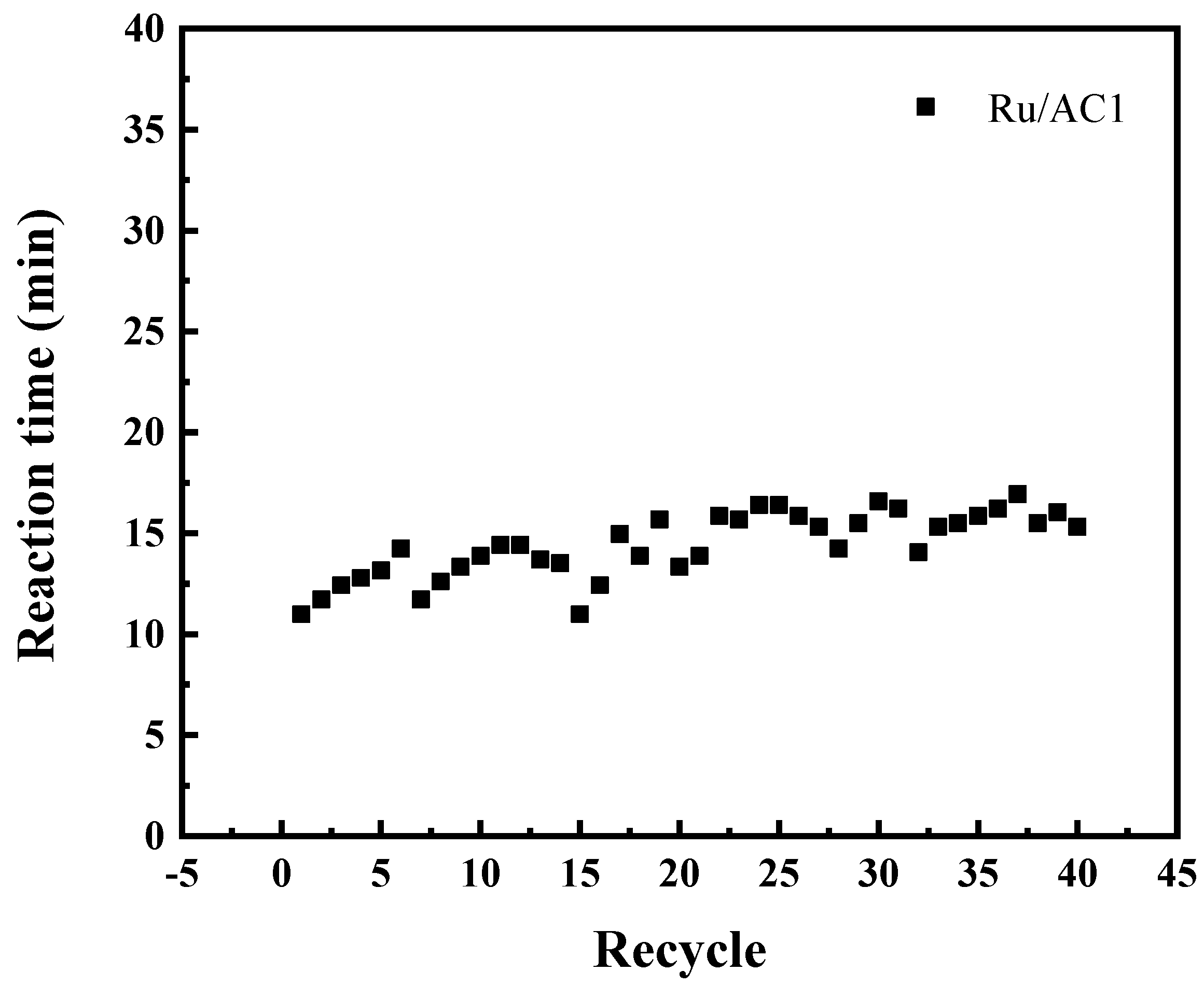
Due to its excellent catalytic activity, Ru/AC1 has been used to carry out catalyst stability experiments. The surface structure of the catalyst before and after use was characterized, and the possible reasons for the decreased activity were analyzed. The stability of the catalyst was examined through a cyclic experiment. The experiment was conducted in the feed liquid (containing 0.3 mol/L HAN, 0.1 mol/L HN, and 1 mol/L HNO3) at a temperature of 80 °C, with a catalyst dosage of 1.0 g. During the cyclic test, the catalyst was separated from the reaction mixture via straightforward filtration. Subsequently, it was directly reused in the following model reactions without undergoing any extra purification procedures. The outcomes of this experiment are presented in Figure 4. The data indicates that the Ru/AC1 catalyst is capable of fully decomposing HAN and HN for at least 40 cycles. With the increase in the number of cycles, the reaction time gradually extended, and the reaction completion time fluctuated by around 11–16 min. The catalyst showed good catalytic activity and stability. The fluctuations in reaction time stem from two aspects. One is the influence exerted by the temperature of the catalyst and the feed liquid, and the other is the result of the gradual loss of active components during multiple cycles.

3.4. SEM

The surface morphology of the catalyst was examined by SEM characterization for both fresh and used Ru/AC1 catalysts, as illustrated in Figure 5. The fresh catalyst exhibits a well-defined and complete pore structure with a smooth surface. However, the utilized catalysts display severe surface corrosion, resulting in the deterioration of the pore structure. This observation suggests that the degradation of the pore structure induced by corrosion represents one of the primary factors contributing to catalyst deactivation.
The surface morphology of the Ru/AC1 catalyst was analyzed using SEM characterization for both fresh and used samples, as shown in Figure 5. The fresh Ru/AC1 catalyst displays a well-preserved and intact pore structure with a smooth surface, indicating that the activated carbon provides a suitable framework for Ru dispersion and catalytic activity. The uniform and open pore structure facilitates efficient mass transfer and accessibility to active sites, which is critical for catalytic performance.
In contrast, the SEM image of the used Ru/AC1 catalyst reveals significant surface corrosion and structural degradation. The once smooth and defined pores appear damaged, with visible collapse and blockage, likely caused by prolonged exposure to the acidic reaction environment. This severe surface deterioration reflects the impact of nitric acid corrosion during the catalytic decomposition process, which weakens the structural integrity of the activated carbon support.
In addition, we utilized the ICP-AES technique to measure the real Ru content in the catalysts. The findings showed that the Ru content in the fresh Ru/AC1 catalyst was 4.8%, while that in the used one was 3.2%. This demonstrates a significant decrease in the Ru concentration. These results imply that there was a considerable reduction in the amount of loaded Ru on the catalysts when they were in use. These observations highlight that the loss of pore structure due to corrosion is a major factor contributing to catalyst deactivation. The collapse of pores reduces the available surface area and active site accessibility, ultimately diminishing the catalyst’s performance. To mitigate this issue, strategies such as using corrosion-resistant materials or introducing protective coatings to the activated carbon surface may be considered to enhance the durability and stability of the catalyst under harsh reaction conditions.

3.5. TEM

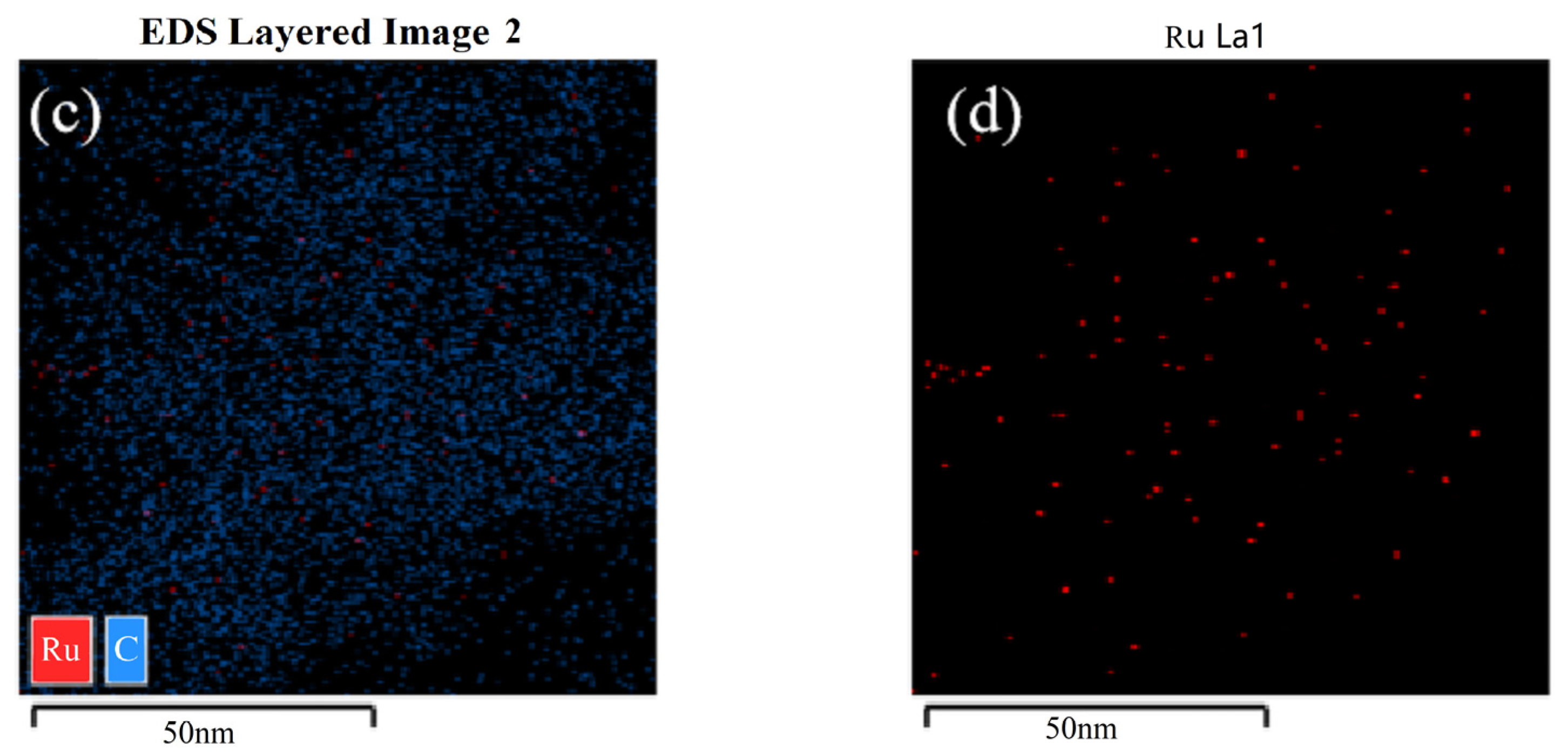
The dispersion of Ru on the catalyst surface was analyzed using transmission electron microscopy (TEM) coupled with energy-dispersive spectroscopy (EDS), as illustrated in Figure 6. In the fresh Ru/AC1 catalyst, Figure 6a shows a uniform distribution of Ru particles across the surface of the activated carbon support, which ensures high accessibility of active sites for catalytic reactions. The dense and homogeneous dispersion of Ru nanoparticles is a critical factor contributing to the high activity of the fresh catalyst.
In contrast, the EDS mapping of the used Ru/AC1 catalyst in Figure 6c reveals a significant reduction in the density of Ru particles on the activated carbon surface. This observation is further supported by the comparison between Figure 6b,d, which clearly shows the decreased Ru signal intensity in the used catalyst. The substantial loss of Ru during the catalytic process can be attributed to harsh reaction conditions, such as nitric acid corrosion and high temperature, which lead to the detachment or leaching of Ru nanoparticles from the support.
This loss of Ru nanoparticles is a major factor contributing to catalyst deactivation, as it reduces the number of active sites available for catalysis. To address this issue, strategies such as enhancing the interaction between Ru and the carbon support, improving Ru anchoring through surface modifications, or employing protective coatings could be considered to mitigate Ru loss and extend catalyst lifetime under operational conditions.

4. Conclusions

In this study, six activated carbon supports were used to prepare Ru/AC catalysts for the catalytic decomposition of hydroxylamine nitrate (HAN) and hydrazine nitrate (HN). The influence of particle size, specific surface area, and structural stability of the supports on catalyst performance was systematically analyzed. The findings revealed that the structural properties of activated carbon play a decisive role in catalytic activity and stability.
(1)
Smaller particle sizes reduced diffusion resistance, while larger specific surface areas enhanced Ru dispersion and increased active sites, resulting in improved catalytic performance. Ru/AC1, with its optimal structural properties, showed the best activity.
(2)
Catalyst deactivation was primarily caused by corrosion-induced pore structure damage and Ru loss during operation, thus reducing active site availability and structural integrity.
(3)
Activated carbons with higher surface areas enabled uniform Ru dispersion and smaller Ru particle sizes, significantly enhancing catalyst activity. Conversely, supports with low surface areas (e.g., AC3) resulted in larger Ru particles and poor performance.

Author Contributions

Writing—original draft, Z.C.; Validation, D.Y. and T.H.; Writing—review & editing, T.L., B.L. and W.Z. Project administration, C.Z. and H.L.; Formal analysis, T.Y. All authors have read and agreed to the published version of the manuscript.

Funding

This research received no external funding.

Data Availability Statement

The data presented in this study are available on request from the corresponding authors.

Conflicts of Interest

Author Deyan Yu was employed by the 404 Company Limited. Authors Zhi Cao, Tiansheng He, Tianchi Li, Chen Zuo, Baole Li, Hongbin Lv, Taihong Yan and Weifang Zheng were employed by the China Institute of Atomic Energy. All authors declare that the research was conducted in the absence of any commercial or financial relationships that could be construed as a potential conflict of interest.

References

  1. Taylor, R.J.; May, I.; Denniss, I.S.; Wallwork, A.L.; Hunt, G.; Hutchison, S.; Bothwell, P.; Richards, V.; Hill, N.J. The Development of Chemical Separation Technology for Advanced Purex Process. In Proceedings of the 5th International Nuclear Conference on Recycling, Conditioning and Disposal (RECOD–98), Nice, France, 25–28 October 1998; Volume 25. [Google Scholar]
  2. Schmieieder, H.; Petrich, G. A concept for improved Purex–process. Radiochem. Acta 1989, 48, 181–186. [Google Scholar] [CrossRef]
  3. Birkett, J.E.; Carrott, M.J.; Fox, O.D.; Jones, C.J.; Maher, C.J.; Roube, C.V.; Taylor, R.J.; Woodhead, D.A. Recent developments in the Purex process for nuclear fuel reprocessing: Complexant based stripping for uranium/plutonium separation. Chimia 2005, 59, 898. [Google Scholar] [CrossRef]
  4. He, H.; Ye, G.; Tang, H.; Zheng, W.; Li, G.; Lin, R. An advanced purex process based on salt–free reductants. Radiochim. Acta 2014, 102, 127–133. [Google Scholar]
  5. Harlow, D.G.; Felt, R.E.; Agnew, S.; Barney, G.S.; McKibben, J.M.; Garber, R.; Lewis, M. Technical Report on Hydroxylamine Nitrate; U.S. Department of Energy: Washington, DC, USA, 1998. [CrossRef]
  6. Herbst, R.S.; Baron, P.; Nilsson, M. Standard and advanced separation: Purex Processes for nuclear fuel reprocessing. In Advanced Separation Techniques for Nuclear Fuel Reprocessing and Radioactive Waste Treatment; Woodhead Publishing: Cambridge, UK, 2011; pp. 141–175. [Google Scholar]
  7. Zhang, Z.; Li, B.; Chen, Q.; Chen, X.; Yan, T.; Zheng, W.; Zuo, C. Catalytic decomposition of hydroxylamine nitrate and hydrazine nitrate using Ru/ZSM-5 catalyst under mild reaction conditions. RSC Adv. 2022, 12, 4469–4474. [Google Scholar] [CrossRef]
  8. Gauthier-Lafaye, F.; Pourcelot, L.; Eikenberg, J.; Beer, H.; Le Roux, G.; Rhikvanov, L.; Stille, P.; Renaud, P.; Mezhibor, A. Radioisotope contaminations from releases of the Tomsk–Seversk nuclear facility (Siberia, Russia). J. Environ. Radioact. 2008, 99, 680–693. [Google Scholar] [CrossRef]
  9. Gerton, R.E. Accident Investigation Board Report on the May 14, 1997, Chemical Explosion at the Plutonium Reclamation Facility, Hanford Site, Richland, Washington—Summary Report; U.S. DOE Office of Environmental Restoration and Waste Management: Washington, DC, USA, 1997.
  10. Jiang, S.J.; Ren, F.Y. Nuclear Fuel Reprocessing Technology; Atomic Energy Press: Beijing, China, 1995. [Google Scholar]
  11. Ren, F.Y.; Zhou, Z.X. Foreign Nuclear Fuel Reprocessing; Atomic Energy Press: Beijing, China, 2006. [Google Scholar]
  12. Chang, S.W. Application of Nitrous Gas in the Conditioning of 1BP Feed Solution. J. Nucl. Radiochem. 2015, 37, 404–407. [Google Scholar]
  13. Wei, C.; Saraf, S.R.; Rogers, W.J.; Mannan, M.S. Thermal runaway reaction hazards and mechanisms of hydroxylamine with acid/base contaminants. Thermochim. Acta 2004, 421, 1–9. [Google Scholar] [CrossRef]
  14. Iwata, Y.; Koseki, H. Risk evaluation of decomposition of hydroxylamine/water solution at various concentrations. Process Saf. Prog. 2002, 21, 136–141. [Google Scholar] [CrossRef]
  15. Breschet, C.; Miquel, P. Improvement of the procedure used to treat highly irradiated fuels. In Proceedings of the International Solvent Extraction Conference, Lyon, France, 8–14 September 1974; London Society of Chemical Industry: London, UK, 1971; pp. 565–576. [Google Scholar]
  16. Bothner-By, A.; Friedman, L. The reaction of nitrous acid with hydroxylamine. J. Chem. Phys. 1952, 20, 459–462. [Google Scholar] [CrossRef]
  17. Koltoonov, V.S.; Marchenko, V.I. Kinetics of hydrazine oxidation by nitrous acid. J. Catal. 1967, 7, 97. [Google Scholar] [CrossRef]
  18. Zhang, Z.F.; Wang, J.F.; Zhang, T.X. Power Reactor Nuclear Fuel Reprocessing Technology; China Atomic Energy Press: Beijing, China, 2013. [Google Scholar]
  19. Hou, X.L.; Zhang, S.Q.; Hu, J.; Wei, X.F.; Zhao, H.G. Study of plutonium valence adjustment in 1AF solution in purex process with nitrogen oxide. Nucl. Sci. Eng. 1995, 15, 165–171. [Google Scholar]
  20. Zhang, S.Q.; Wei, X.F.; Ye, G.A.; Zhang, X.Y.; Zhuang, W.X.; Liu, S.Y.; Fu, L.C. Research on Regulating Plutonium Valence State with N2O4 in Purex Process. Atom. Energy Sci. Technol. 1993, 72, 130–137. [Google Scholar]
  21. Yu, D.; Li, B.; Cao, Z.; Chen, Q.; Zuo, C.; He, T.; Yan, T.; Zheng, W. Catalytic decomposition of hydrazine nitrate hydroxylamine nitrate in radioactive nitric acid waste liquid using Ru/AC catalyst. New J. Chem. 2024, 48, 8660–8666. [Google Scholar] [CrossRef]
  22. Li, B.L.; Yu, D.Y.; Cao, Z.; He, T.S.; Chen, S.W.; Zheng, W.F. Effect of acid-treatment on the activated carbon of Ru/AC catalysts for catalytic decomposition of hydroxylamine nitrate and hydrazine nitrate. Appl. Catal. A Gen. 2024, 681, 119801. [Google Scholar] [CrossRef]
  23. Li, B.L.; He, T.S.; Zuo, C.; Cao, Z.; Yang, T.H.; Zheng, W.F. The reaction kinetics and mechanism of catalytic decomposition of hydrazine nitrate on Ru/C catalyst in nitric acid solutions. New J. Chem. 2023, 47, 7583–7587. [Google Scholar] [CrossRef]
  24. Cao, Z.; Li, T.C.; Li, B.L.; Chen, X.W.; Zuo, C.; Zheng, W.F. Study on the Deactivation Mechanism of Ru/C Catalysts. Processes 2024, 12, 1138. [Google Scholar] [CrossRef]
  25. Zhong, Z.; Aika, K. The Effect of Hydrogen Treatment of Active Carbon on Ru Catalysts for Ammonia Synthesis. J. Catal. 1998, 173, 535–539. [Google Scholar] [CrossRef]
  26. Aksoylu, A.; Madalena, M.; Freitas, A.; Pereira, M.R.; Figueiredo, J.L. The effects of different activated carbon supports and support modifications on the properties of Pt/AC catalysts. Carbon 2001, 39, 175–185. [Google Scholar] [CrossRef]
  27. Raróg-Pilecka, W.; Szmigiel, D.; Komornicki, A.; Zieliński, J.; Kowalczyk, Z. Catalytic properties of small ruthenium particles deposited on carbon. Ammonia decomposition studies. Catal. Today 2003, 41, 589–591. [Google Scholar]
  28. Kang, M.; Bae, Y.S.; Lee, C.H. Effect of heat treatment of activated carbon supports on the loading and activity of Pt catalyst. Carbon 2005, 43, 1512–1516. [Google Scholar] [CrossRef]
  29. Feng, W.; Kwon, S.; Borguet, E.; Vidic, R. Adsorption of Hydrogen Sulfide onto Activated Carbon Fibers: Effect of Pore Structure and Surface Chemistry. Environ. Sci. Technol. 2005, 39, 9744–9749. [Google Scholar] [CrossRef] [PubMed]
  30. Rey, A.; Zazo, J.A.; Casas, J.A.; Bahamonde, A.; Rodriguez, J.J. Influence of the structural and surface characteristics of activated carbon on the catalytic decomposition of hydrogen peroxide. Appl. Catal. A Gen. 2011, 402, 146–155. [Google Scholar] [CrossRef]
  31. Kowalczyk, Z.; Sentek, J.; Jodzis, S.; Mizera, E.; Góralski, J.; Paryjczak, T.; Diduszko, R. An alkali–promoted ruthenium catalyst for the synthesis of ammonia, supported on thermally modified active carbon. Catal. Lett. 1997, 45, 65–72. [Google Scholar] [CrossRef]
  32. Liu, J.; Liu, Y.; Peng, J.; Liu, Z.; Jiang, Y.; Meng, M.; Zhang, W.; Ni, L. Preparation of high surface area oxidized activated carbon from peanut shell and application for the removal of organic pollutants and heavy metal ions. Water Air Soil Pollut. 2018, 229, 391. [Google Scholar] [CrossRef]
  33. Heidarinejad, Z.; Dehghani, M.H.; Heidari, M.; Javedan, G.; Ali, I.; Sillanpää, M. Methods for preparation and activation of activated carbon: A review. Environ. Chem. Lett. 2020, 18, 393–415. [Google Scholar] [CrossRef]
  34. Ahmad, A.A.; Idris, A. Preparation and characterization of activated carbons derived from bio-solid: A review. Desalination Water Treat. 2014, 52, 4848–4862. [Google Scholar] [CrossRef]
  35. Januszewicz, K.; Kazimierski, P.; Klein, M.; Kardaś, D.; Łuczak, J. Activated carbon produced by pyrolysis of waste wood and straw for potential wastewater adsorption. Materials 2020, 13, 2047. [Google Scholar] [CrossRef]
  36. Rashidi, N.A.; Yusup, S. Biochar as potential precursors for activated carbon production: Parametric analysis and multi-response optimization. Environ. Sci. Pollut. Res. 2020, 27, 27480–27490. [Google Scholar] [CrossRef] [PubMed]
  37. Ma, M.J.; Ying, H.J.; Cao, F.F.; Wang, Q.; Ai, N. Adsorption of congo red on mesoporous activated carbon prepared by CO2 physical activation. Chin. J. Chem. Eng. 2020, 28, 1069–1076. [Google Scholar] [CrossRef]
  38. Louarrat, M.; Enaime, G.; Baçaoui, A.; Yaacoubi, A.; Blin, J.; Martin, L. Optimization of conditions for the preparation of activated carbon from olive stones for application in gold recovery. J. S. Afr. Inst. Min. Metall. 2019, 119, 297–306. [Google Scholar] [CrossRef]
  39. Bhatnagar, A.; Hogland, W.; Marques, M.; Sillanpää, M. An overview of the modification methods of activated carbon for its water treatment applications. Chem. Eng. J. 2013, 219, 499–511. [Google Scholar] [CrossRef]
  40. Xing, L.; Xie, Y.; Cao, H.; Minakata, D.; Zhang, Y.; Crittenden, J.C. Activated carbon-enhanced ozonation of oxalate attributed to HO· oxidation in bulk solution and surface oxidation: Effects of the type and number of basic sites. Chem. Eng. J. 2014, 245, 71–79. [Google Scholar] [CrossRef]
  41. Prahas, D.; Wang, M.J.; Ismadji, S.; Liu, J.C. Enhanced adsorption of quaternary amine using modified activated carbon. Water Sci. Technol. 2014, 69, 2085–2092. [Google Scholar] [CrossRef] [PubMed]
  42. Lu, X.; Yim, W.-L.; Suryanto, B.H.R.; Zhao, C. Electrocatalytic oxygen evolution at surface oxidized multiwall carbon nanotubes. J. Am. Chem. Soc. 2015, 137, 2901–2907. [Google Scholar] [CrossRef]
  43. Zou, Y.; Wang, X.; Khan, A.; Wang, P.; Liu, Y.; Alsaedi, A.; Hayat, T.; Wang, X. Environmental remediation and application of nanoscale zero-valent iron and its composites for the removal of heavy metal ions: A review. Environ. Sci. Technol. 2016, 50, 7290–7304. [Google Scholar] [CrossRef] [PubMed]
  44. Hao, S.; Yu, Z.; Liu, X. Surface modification of activated carbon and its effects on methane adsorption. Appl. Mech. Mater. 2013, 395–396, 605–609. [Google Scholar] [CrossRef]
  45. Van Pelt, A.H.; Simakova, O.A.; Schimming, S.M.; Ewbank, J.L.; Foo, G.S.; Pidko, E.A.; Hensen, E.J.; Sievers, C. Stability of functionalized activated carbon in hot liquid water. Carbon 2014, 77, 143–154. [Google Scholar] [CrossRef]
  46. Tangsathitkulchai, C.; Ngernyen, Y.; Tangsathitkulchai, M. Surface modification and adsorption of eucalyptus wood-based activated carbons: Effects of oxidation treatment, carbon porous structure and activation method. Korean J. Chem. Eng. 2009, 26, 1341–1352. [Google Scholar] [CrossRef]
  47. Zhao, H.H.; Song, H.L.; Zhao, J.; Yang, J.; Chou, L.J. The Reactivity and Deactivation Mechanism of Ru@C Catalyst over Hydrogenation of Aromatics to Cyclohexane Derivatives. ChemistrySelect 2020, 5, 4316–4327. [Google Scholar] [CrossRef]
  48. Lin, B.Y.; Qi, Y.C.; Guo, Y.J.; Lin, J.X.; Ni, J. Effect of potassium precursors on the thermal stability of K-promoted Ru/carbon catalysts for ammonia synthesis. Catal. Sci. Technol. 2015, 5, 2829–2838. [Google Scholar] [CrossRef]
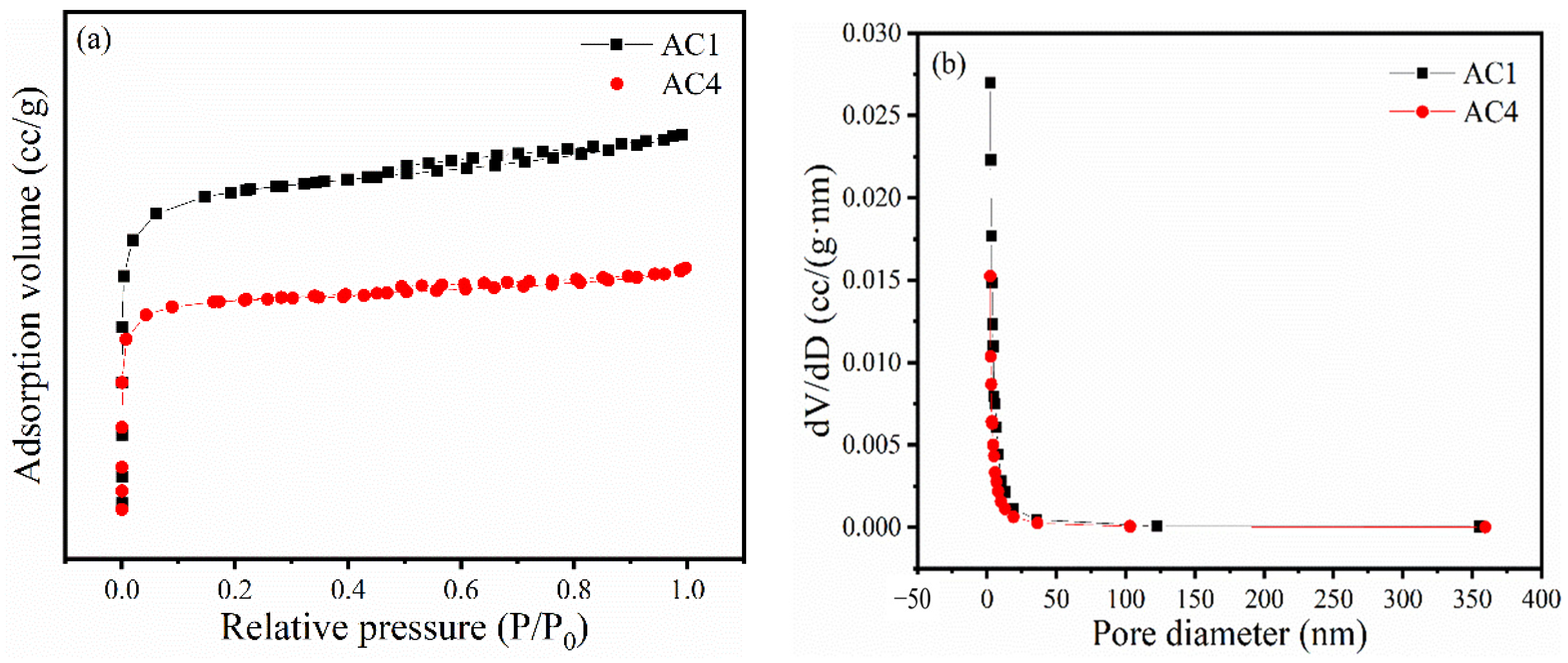
Figure 1. The (a) absorption (desorption) curve and (b) pore size distribution curve of AC1 and AC4.
Processes 13 00641 g001
Figure 2. Comparative analysis of catalyst activity and reaction time.
Processes 13 00641 g002
Figure 3. XRD images of Ru/AC1, Ru/AC2, and Ru/AC3. * indicates the diffraction peaks corresponding to the characteristic crystal planes of Ru.
Processes 13 00641 g003
Figure 4. Stability test for the decomposition of HAN and HN of Ru/AC1.
Processes 13 00641 g004
Figure 5. SEM images of (a) fresh and (b) used Ru/AC1 catalysts.
Processes 13 00641 g005
Figure 6. TEM-EDS images of (a,b) fresh and (c,d) used Ru/AC1.
Processes 13 00641 g006aProcesses 13 00641 g006b
Table 1. Physical and structural parameters of activated carbons and fresh and used catalysts.
EntryCatalystSBET (m2/g)Pore Volume (cm3/g)Pore Size (nm)
1AC1787.80.461.17
2Ru/AC1665.40.391.18
3used Ru/AC1606.40.371.25
4AC2516.10.301.17
5Ru/AC2488.50.291.17
6used Ru/AC2430.60.261.19
7AC326.90.032.55
8Ru/AC38.80.025.09
9used Ru/AC345.80.062.60
10AC4448.80.291.28
11Ru/AC4421.50.251.18
12used Ru/AC4300.80.181.19
13AC5721.10.401.11
14Ru/AC5572.20.331.15
15used Ru/AC5464.90.271.17
16AC6811.70.441.09
17Ru/AC6587.50.321.11
18used Ru/AC6568.20.321.15
Disclaimer/Publisher’s Note: The statements, opinions and data contained in all publications are solely those of the individual author(s) and contributor(s) and not of MDPI and/or the editor(s). MDPI and/or the editor(s) disclaim responsibility for any injury to people or property resulting from any ideas, methods, instructions or products referred to in the content.