Abstract
This paper presents a novel Proportional Damping Injection (P + d) control scheme that incorporates a damping regulation strategy and an adaptive method for networked telerobotic systems. Unlike the traditional P + d controller with a fixed damping coefficient, the proposed approach includes a dynamic damping adjuster, designed based on position error, to enhance the position tracking speed and improve the system robustness. To address uncertainties in dynamic models and external forces, Radial Basis Function (RBF) neural networks and an adaptive strategy are employed for dynamic estimation. The closed-loop stability of the teleoperation system was rigorously established using the Lyapunov–Krasovskii method, and the relationship between the controller gains and communication delay boundaries was explicitly derived. Finally, simulations and experimental results validated the system’s stability and effectiveness, demonstrating the advantages of the proposed controller.
1. Introduction
Teleoperation robotics greatly expands the range of human perception and operations. Based on teleoperation systems, people can manipulate robots to complete complex tasks from a distance, being widely used in nuclear operations, space and ocean exploration, remote surgery, and so on [1,2,3]. A conventional bilateral telerobotic system consists of a master robot, a master controller, a slave robot, a slave controller, and a communication network. For teleoperation systems, stable movement and precise position tracking are important performance indicators. However, in practical systems, time delays in signal transmission, model uncertainty, and external interference forces can weaken the performance [4,5]. Therefore, it is necessary to fully consider these negative factors in controller design.
In a teleoperation system, the communication channel is utilized to transmit position and control signals. However, this process inevitably introduces communication delays, which can degrade the control performance and potentially destabilize the closed-loop system [6]. The primary challenge in designing a control structure is addressing the adverse effects of time delays on system stability. Consequently, the stability analysis and performance enhancement of time-delayed telerobotic systems have become a significant area of research. Based on passivity theory, methods such as the scattering approach and wave variable method were initially developed to ensure the passivity of communication delays and maintain the stabilization of the system [7,8]. Improved passivity-based methods have also been applied to fixed-delay teleoperation systems to achieve position synchronization [9,10]. To address the limitations of passivity theory, some new methods have been proposed to overcome its inherent conservatism. Various advanced control techniques have been employed for position tracking in time-delayed teleoperation systems, such as robust control [11], sliding mode control [12], feedforward and feedback control [13], observer-based approaches [14], finite-time control [15,16], and so on.
Another issue in telerobotics control is the uncertainty of dynamic models. The implementation of the above classic control methods heavily depends on accurate dynamic models. However, in practical systems, obtaining precise dynamic descriptions is often challenging. To address this issue, adaptive control methods have been introduced to enable telerobotic position control, despite unknown or imprecise dynamic models. Typically, estimation models based on linear parameterization [17,18], neural networks [19,20,21,22,23,24,25], and fuzzy systems [26] are employed to handle uncertainties in dynamic modeling. Among them, neural-network-based adaptive control methods have been extensively employed in the position tracking control of telerobotic systems. In [22,24], a type-2 fuzzy neural network and a damping zeroing neural network were utilized to estimate unknown dynamics and kinematics. In [19,20,21,23,25], an adaptive control method based on a Radial Basis Function Neural Network (RNFNN) was more extensively applied in the control of telerobotics with network time delays. With certain inherent advantages, such as a strong local approximation capability, fast learning convergence, and effective handling of nonlinear dynamics, RBFNNs demonstrate outstanding performance in compensating for uncertainties in dynamic models and estimating external forces. Additionally, the RBFNN-based adaptive method enhances the passivity of time-delayed teleoperation systems, thereby improving the stability and robustness of closed-loop systems. In recent years, methods based on reinforcement learning [27], combinatorial learning [28], and data-driven learning [29] have been used in the motion control of robots and other mechanisms to adapt to model uncertainty and environmental changes, achieving good control effects. These may also be directions for improving the control methods of teleoperated robots.
The Proportional Damping Injection (P + d) control method is commonly employed for position control in time-delayed telerobotics. The inclusion of a velocity damping term ensures the stability of telerobotics [30]. Compared to other control methods, a P + d controller features a simple controller structure and is easy to implement in practical applications. In [31], a simplified P + d controller was designed for telerobotic systems. Similarly, the work in [32] expressed a novel PD+d controller designed specifically for asymmetric time-delayed teleoperation systems. In [33,34,35], some P + d-like controllers were developed to achieve both position synchronization and force tracking control.
In these methods, the robot’s gravity torque is typically treated as known to enable gravity calculation within the controller. Additionally, the external forces acting on the robot are often assumed to be passive. However, when the external force is non-zero or does not meet the passivity condition, the position error cannot asymptotically converge to a negligible range near zero. To address these problems, some improved methods assume the external force is known and incorporate it into the control law, thereby enhancing the position synchronization control performance. In practical robotic systems, accurately obtaining the dynamics of gravity torques, friction torques, and external forces is a great challenge. The adaptive control method offers an effective solution by estimating the uncertain components and unknown signals of these dynamics. In some advanced damping injection control methods, adaptive techniques are employed to estimate the dynamic parameters and external forces. In [36], a nonlinear P + d control approach was presented, where an adaptive term was applied to estimate the environmental forces on the slave side. Similarly, the work in [37], presented a fuzzy system combined with an adaptive method for unknown force compensation, leading to the proposal of a PD+d control scheme.
The core of the P + d control method is the damping term. The introduction of a damping term can consume system energy and put the closed-loop system in a stable convergence state. However, an excessively large damping term can also lead to slower convergence in position tracking. In the control methods mentioned above, the damping term is typically fixed. However, in the process of position tracking control, it is desirable to have a large damping coefficient when the position error is large, to ensure the stability and convergence trend of the system. When the position error decreases, it is desirable to reduce the damping coefficient to achieve a faster convergence speed. A fixed damping coefficient makes it difficult to achieve such a goal. There is a need for the damping term to be adaptively adjusted, improving the system’s response speed by reducing the damping injection, while maintaining system stability. In [38], Yang et al. proposed an enhanced P + d control strategy for time-varying delayed teleoperation systems, incorporating damping adjustment via a velocity nonlinearity term and position error. However, velocity singularity factors within the controller can lead to oscillations during position control.
Based on the above observations, current research on interactive control methods for telerobotics has predominantly focused on fixed damping coefficient control schemes, with relatively less attention given to methods for adjusting damping coefficients. Additionally, some existing controller structures remain somewhat complex from a system implementation perspective. Motivated by these challenges, this paper proposes a novel, improved proportional damping adaptive control method for telerobotic systems. A new mechanism is introduced for adaptive adjustment of the damping coefficient during the control process. To address dynamic uncertainties and external forces, a Radial Basis Function Neural Network (RBFNN) and adaptive methods are incorporated. Stability analysis of the closed-loop system is performed, and the relationship between the controller gain and communication delay in the telerobotic system is explored. The main contributions of this paper are summarized as follows:
- Differently from existing works in [31,32,33,34,35,36,37], a novel, improved P + d control scheme with a damping adjustment strategy and adaptive method is presented. Compared to the work in [38], the proposed damping adjustment strategy effectively avoids the issue of control signal oscillations caused by velocity singularities. This improvement ensures a smoother and more stable control performance. By incorporating the proposed damping coefficient adjustment and adaptive approach, the convergence speed of position errors and the robustness of the closed-loop telerobotic system can be enhanced.
- In this paper, a RBFNN and adaptive control method are utilized for uncertain dynamics and unknown external force compensation, and the precise gravity torque and external forces do not need be accurately obtained.
- In this paper, the Lyapunov–Krasovskii function is constructed for stability analysis of the telerobotic system, and the relationship between controller gains and the upper bounded communication delays is obtained.
The remainder of the paper is stated as follows: In Section 2, a dynamic description and some useful properties are given. In Section 3, the proposed control scheme is first illustrated, and the stability theorem of the telerobotic systems and proof process are given. In Section 4, the implementation process and results of the simulations and experiments are presented. Finally, the conclusions of this paper are provided.
2. Dynamics
In this section, the model description of the telerobotic system is presented. The master and slave robots are both modeled as manipulators with n-DOF and rotational joints. The dynamics cen be described as
where m and s, respectively, denote the master robot and the slave robot. , , , , , , and represent the vectors of joint position, velocity, and acceleration for the master robot and slave robot at time . , , , and represent the inertia, coriolis and centrifugal matrixes, and gravitational and friction torques. and are the control torques. and are the Jacobian matrices of the telerobotic system. and are the operating force acting on the master robot and the environmental force applied to the slave robots, respectively.
The following are certain properties of robot dynamics that are later used for the controller development and stability analysis [39,40]:
Property 1.
For , the matrix is characterized by its positive definiteness and symmetry, and for the identity matrix , there exist positive scalars and , such as
Property 2.
The matrix is skew symmetric. For any vector , there is
Property 3.
For any vector , position and velocity vectors , and , , such that the inequality holds.
Property 4.
If the velocity and acceleration vectors and are all bounded, the matrixes and are also bounded.
Remark 1.
In a telerobotic system, the position information of the robots needs be transmitted between the master and slave sides. For the controller design and the stability analysis, it is essential to define the characteristics of the communication delay signals. Let represent the communication delay between the master controller and the slave controller, and denotes the communication delay between the slave controller and the master controller. In [41], the author discussed control signal transmission and distributed efficient processing methods, which represents a promising approach for alleviating communication delay problems and deserves further exploration. These delay signals must satisfy the following assumptions:
Assumption 1.
The time-varying communication delays between the master and the slave robots are all bounded, and the rates of the delay change are also bounded, for , there are
where is the upper bound of delay.
3. Controller Design and Stability Analysis
In this section, a novel proportional damping control scheme with adjustable damping gain is proposed for a telerobotic system. The control scheme includes one damping adjustment term, one proportional term, one damping term, and one compensation term.
3.1. Controller Design
First, the position synchronization error of the master and slave side and are defined as
If there is a vector , function is defined as .
Building upon the traditional P + d control method, the proposed controller can be designed as described in (7), incorporating additional mixed damping, gravity, and adaptive compensation terms.
where is the influencing factor of the mixed damping term. are the weight coefficients of the mixed damping term, respectively. are the damping gains, are the proportional gains. are compensation items, which are designed as
Remark 2.
In our proposed control laws, the hybrid damping-adjustment term (for ) is introduced based on position errors, to enhance the robustness and speed of position synchronization control under time-varying delays. The position tracking error is applied to construct the hybrid term, enabling damping adjustment. When the position error is relatively large, an additional larger damping can be obtained to ensure the robustness of the system. Conversely, when the tracking error is small, the damping parameter is reduced, to facilitate faster error convergence. Compared to the existing method in [38], the proposed damping adjustment approach avoids the singularity problem caused by small velocity signals. Additionally, an exponential function of time t is introduced as a weight coefficient for the damping adjustment term, to guarantee bounded convergence. However, as is well known, the exponential function decreases as time increases, which can weaken the effect of the damping adjustment term. Therefore, ν is typically set to a very small value, to ensure the damping adjustment term remains effective for a sufficiently long period.
In this work, an RBFNN is utilized to estimate the friction torque and external forces acting on the robot. Based on the definition of the RBFNN, there are and . For , is the weight matrix of the RBFNN, is the Gauss function vector, and is the bounded estimate vector. and are the estimate parameter matrix and vector of the RBFNN. If the position and velocity signals and of the robot are used as inputs of the RBFNN, there is . If the RBFNN has l nodes, then the Gauss function vector can be calculated as
and w are the center vector and the width of the Gauss function. In practice, adaptive methods are generally used to design adaptive learning laws to estimate and , so the estimation matrix and vector are used instead of and . The adaptive learning rates are ultimately designed as the following expressions:
3.2. Stability Analysis
The stability performance and controller gain conditions of the time-delay telerobotic system are represented based on the following theorem:
Theorem 1.
For the nonlinear telerobotics system described in (1), in the presence of asymmetric communication delays, uncertain dynamic parameters, and unknown external forces, the closed-loop system is stable when the controller in (7) and the adaptive learning rates in (10) are applied. The synchronization errors and , as well as the adaptive coefficients , , , and are all bounded, provided that the following inequalities of the controller gains can be established:
Remark 3.
The Lyapunov–Krasovsky (LK) method is a powerful tool for analyzing time-delay systems, as it not only considers the system’s state at different times, but also includes integral terms with the time delay, which can directly capture the effects caused by the time delay. The L-K function is typically constructed as a positive definite scalar function, which mainly consists of two parts: the quadratic term of the telerobotic system state and the term that integrates the states over a time delay interval. Normally, the stability analysis of closed-loop telerobotic systems is carried out according to the following steps: Firstly, a suitable Lyapunov–Krasovskii (LK) function is constructed. Subsequently, the derivative of the LK function is calculated and substituted into the control law and adaptive learning law for inequality scaling and simplification. Finally, the boundedness of the LK function is proved using the scaled inequality, thereby further obtaining the boundedness of the system state and the stability of the system. Based on Theorem 1, the relationship (11) between the master and slave communication delays and the controller gains is presented. By utilizing this relationship, when the communication delay is known, this can help to select the appropriate controller coefficients. Once the controller gains are set, they can limit the upper bound of the communication delays.
Remark 4.
In control laws, , , , , , and are important parameters. First, , , , and should satisfy the inequality relationship (11) to ensure the stability of the system. The parameters and are defined as proportional gain coefficients, and the magnitudes determine the convergence rate of the tracking error. However, excessively large values of and can weaken the system stability and cause oscillations in the control process. The parameters and are denoted as damping gains. Theoretically, the larger the damping gain, the greater the system stability. Nonetheless, excessive damping coefficients can reduce the convergence speed of the tracking error. The parameter η represents the weight of the adaptive damping adjustment term. For an RBFNN, the approximation accuracy is directly proportional to the number of nodes. However, if the number of nodes is excessively large, the computational load of the network will also increase. Typically, the number of nodes is initially set to twice the dimensionality of the input data and adjusted based on simulation and experimental results.
Next, the main proof of Theorem1 is presented, as follows:
Proof of Theorem 1.
Firstly, a Lyapunov–Krasovskii functional is defined as V as
Secondly, with the properties of robotics, control laws in (7), and the properties of the hyperbolic tangent function , the derivative over time of can be derived as
where . The detailed process of the above proof is given in Appendix A.
Then, the derivative of is
Based on the equality relationships in Appendix B, we have
The derivative of can be expressed as follows:
Considering that the following inequality always holds
We can obtain that
With the adaptive learning rates developed in (10), the derivative of is
Then, we have that
We give a new definition that , , , then there has
where is denoted as
Finally, we can analyze the boundedness and stability of the system state through the following content. If the inequalities of controller gains (11) hold, it can be obtained that
where . If the above inequality is integrated from 0 to t, we have
As , then is bounded. Subsequently, it can be concluded that and are all bounded, and , . Based on the Lyapunov functions, , , , , , , and are all bounded.
With the definitions of tracking errors, we have
then, and are all bounded. □
With the control law (7) and dynamic of the slave 1, we have
Then, with Property 1, Property 3, Property 4, and the above conclusions, it can be concluded that the angular acceleration signal is bounded. Following a similar analysis methods, it can also be obtained that . With Equation (28), it follows that and are also bounded.
And differentiating the above equation to time
Additionally, based on the properties of the dynamics and the above conclusions, it can be observed that is also bounded. Therefore, applying Barbalat’s Lemma, it is easy to obtain that . With the closed loop dynamic in (1), we have . As defined in (6), we have , which demonstrates the asymptotic zero convergence of the position tracking.
4. Simulations and Experiments
4.1. Simulations
A simulated telerobotic system consisting of one master and one slave manipulator was implemented in MATLAB to validate the proposed method. Each robot had a two-link mechanism with two rotational joints. The dynamics of a single manipulator in the simulated teleoperation system can be found in [42], and the parameters of the models were selected as in Table 1.

Table 1.
Simulation dynamic parameters of teleoperation system.
In the simulation, two contact environment models were introduced separately to the slave robots, and the contact models were defined as
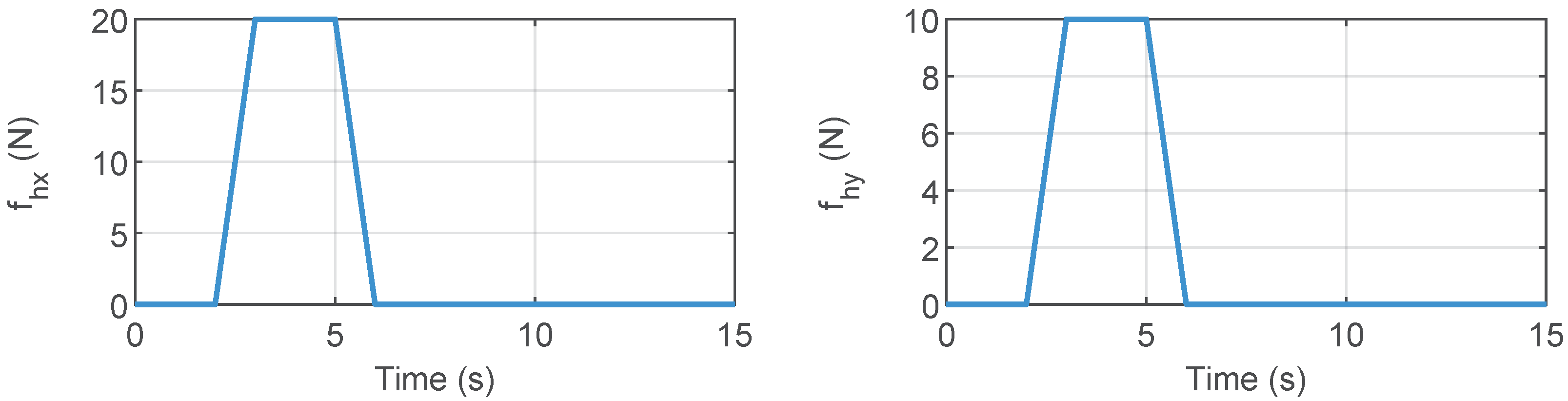
where and are the position and velocity vectors in Cartesian coordinates, which can be obtained using kinematics and differential movements. is the initial position vector. and are the damping and stiffness gains. In this simulation, the parameters described above were set as , , . On the master side, an external force was applied to simulate the operator’s action on the robot. Figure 1 illustrates the external forces applied by the human operator. These forces were exerted in the and directions between 2 and 6 s. The communication delays were defined as and , with the corresponding delays illustrated in Figure 2. The gains for the control laws were selected as follows: , , , , , and . The initial joints are set as , .
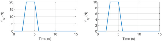
Figure 1.
External operator forces in the x- and y-directions.
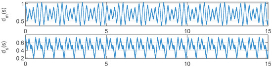
Figure 2.
Asymmetric master and slave side communication delay signals.
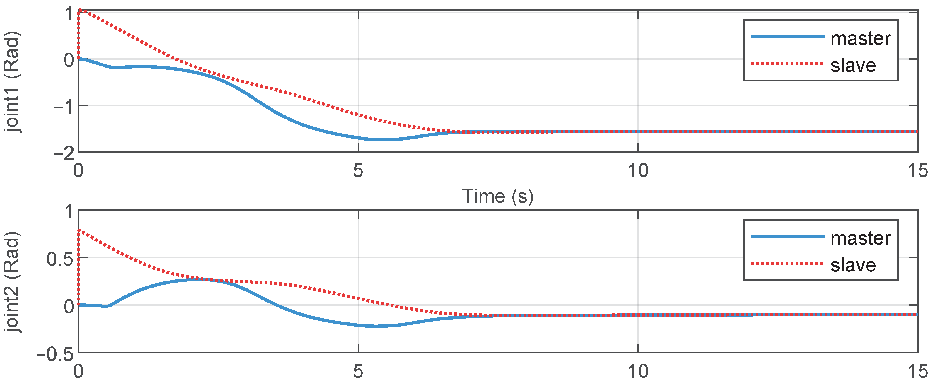
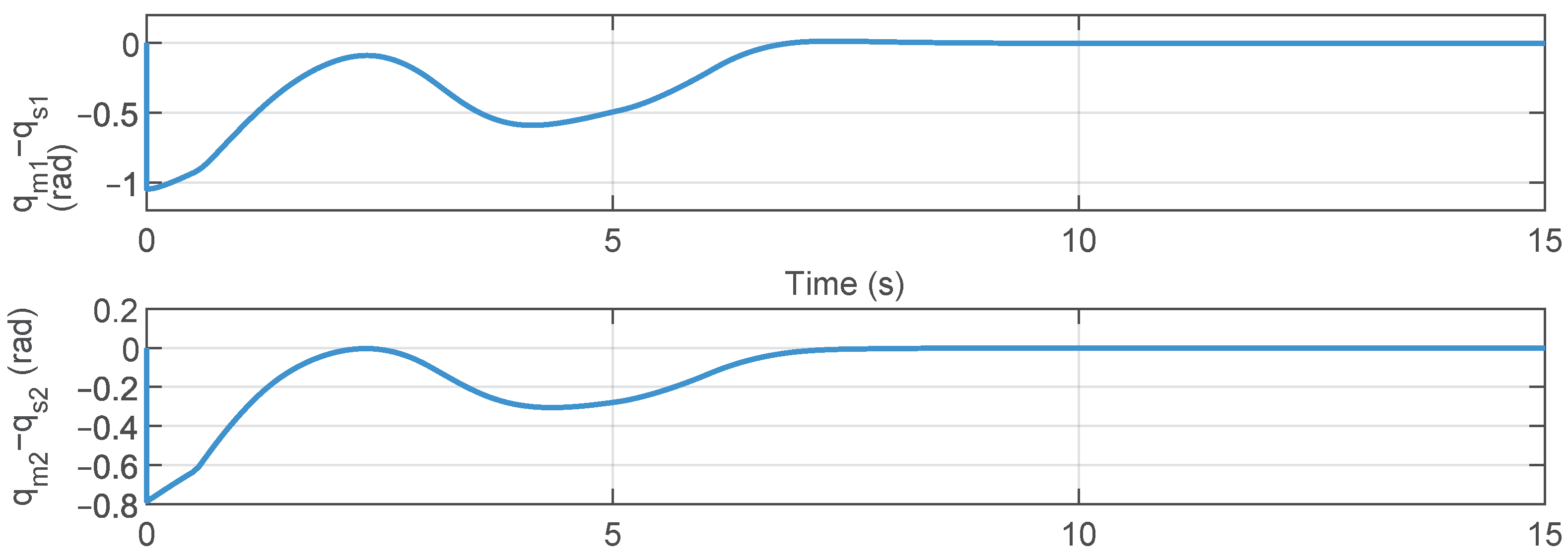
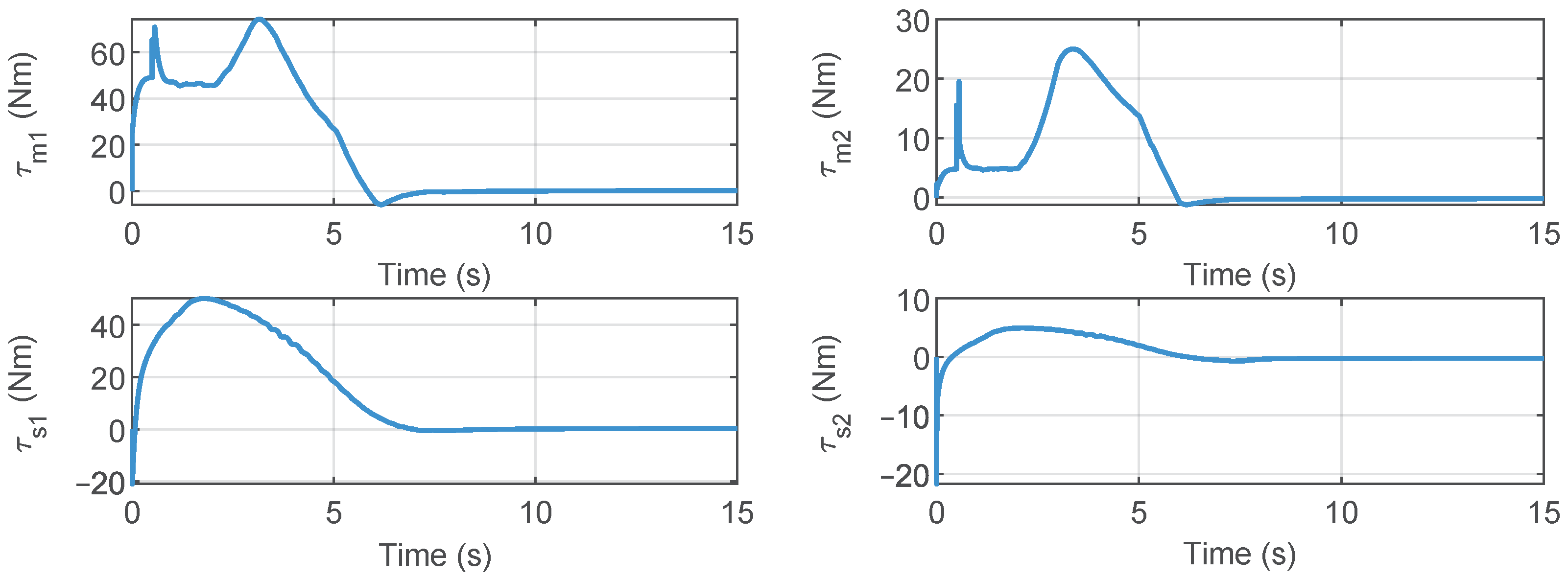
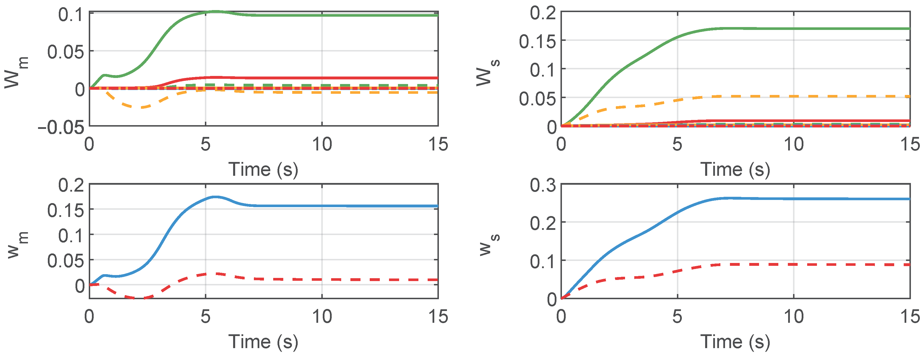
Figure 3, Figure 4, Figure 5, Figure 6, Figure 7, Figure 8, Figure 9, Figure 10 and Figure 11 show the results of the simulation experiment. Figure 3 shows the joint position tracking control performance. When the operator external forces were applied between 2 and 6 s, the joint positions deviated from their initial positions. After the operator force was removed, the joints could achieved a stable tracking performance. Figure 4 illustrates the joint synchronization errors of the master and slave robot. As demonstrated in Figure 3 and Figure 4, when the applied operational force was removed, the joint positions of the master and slave robots achieved stable synchronous tracking within approximately 8 s. The joint control torques are shown in Figure 5, while Figure 6 displays the results of the adaptive gains. The joint control torques are shown in Figure 5, while Figure 6 displays the results of the adaptive gains. Figure 5 and Figure 6 further corroborate that once the positional synchronous tracking was achieved, both the control torque and adaptive parameters remained in a stable state. These simulation results demonstrate that, based on the proposed control method, the telerobotic system could achieve stable position tracking performance.
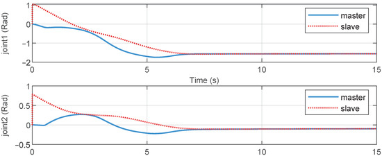
Figure 3.
Joint positions of master and slave robots.
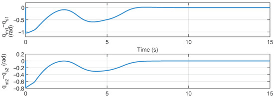
Figure 4.
Tracking errors between the master and the slave robots.
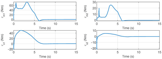
Figure 5.
Control torques of master and slave robots.
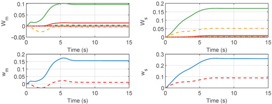
Figure 6.
Adaptive parameters of master and slave robots.
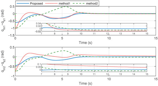
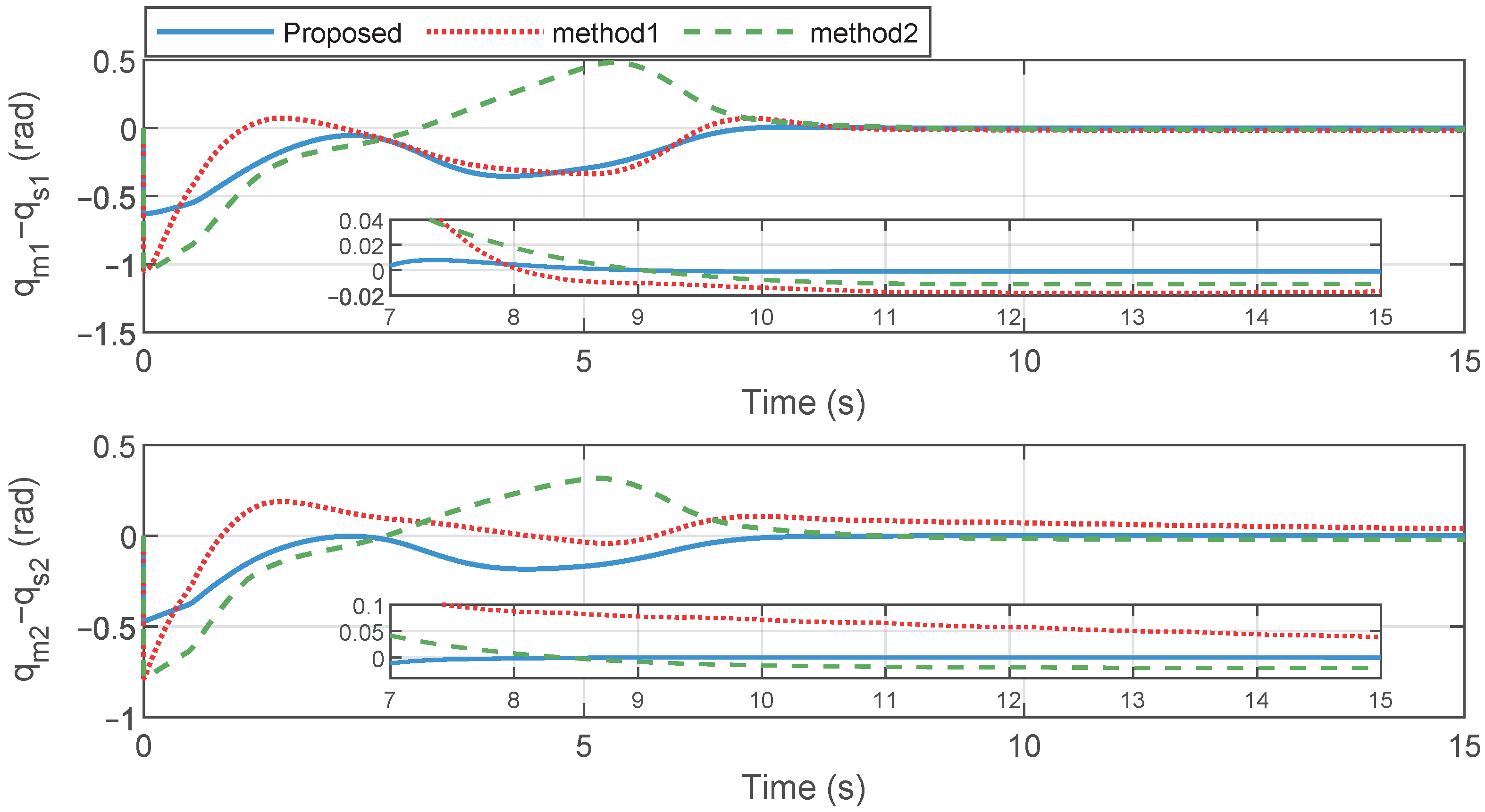
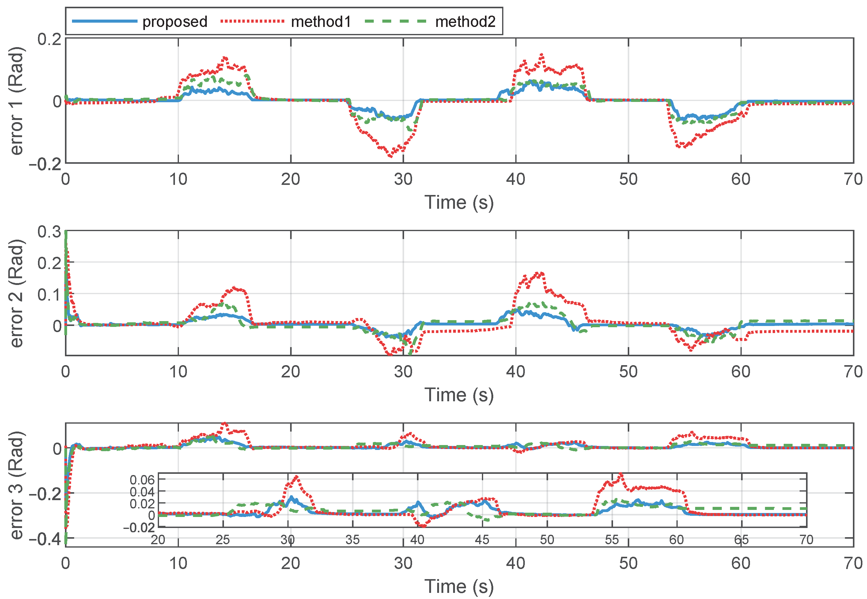
Figure 7.
Tracking error comparisons: proposed method, method 1, and method 2.
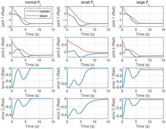
Figure 8.
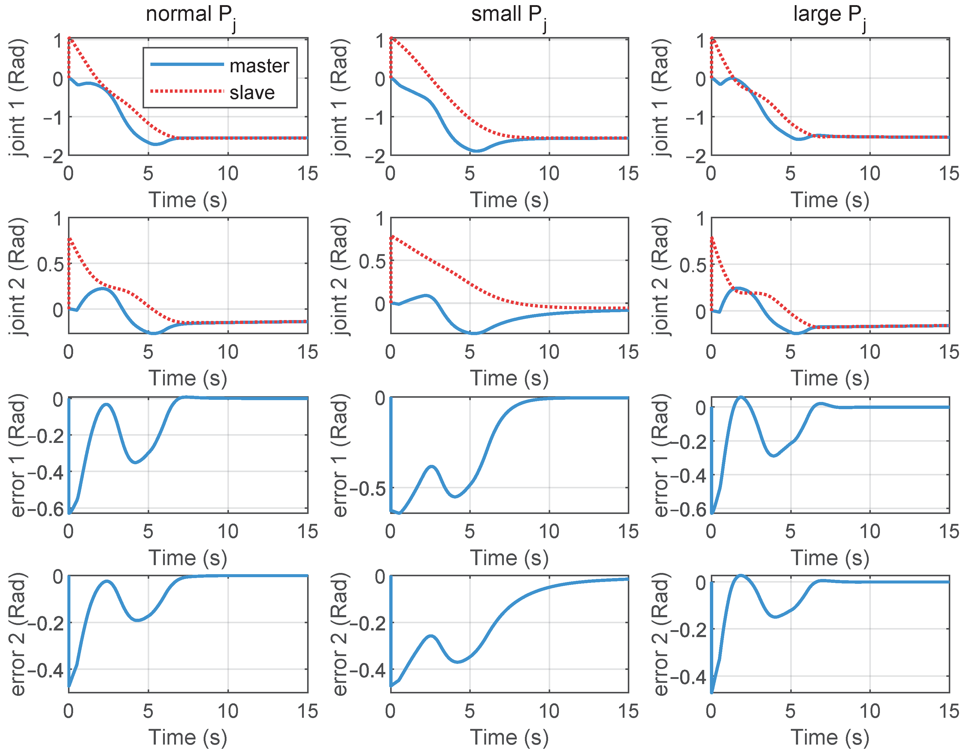
Position tracking and position error curves of the telerobotic system under different proportional gains .
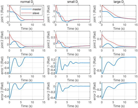
Figure 9.
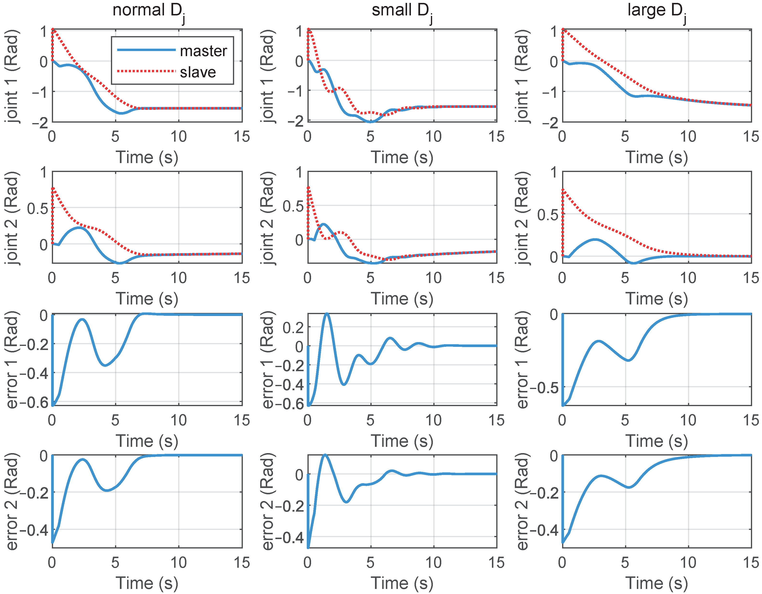
Position tracking curves of the telerobotic system with different damping gains .
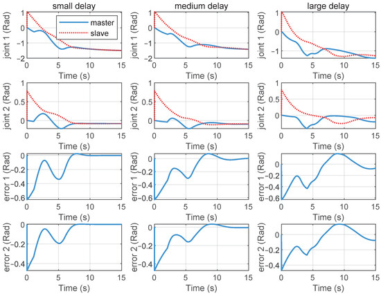
Figure 10.
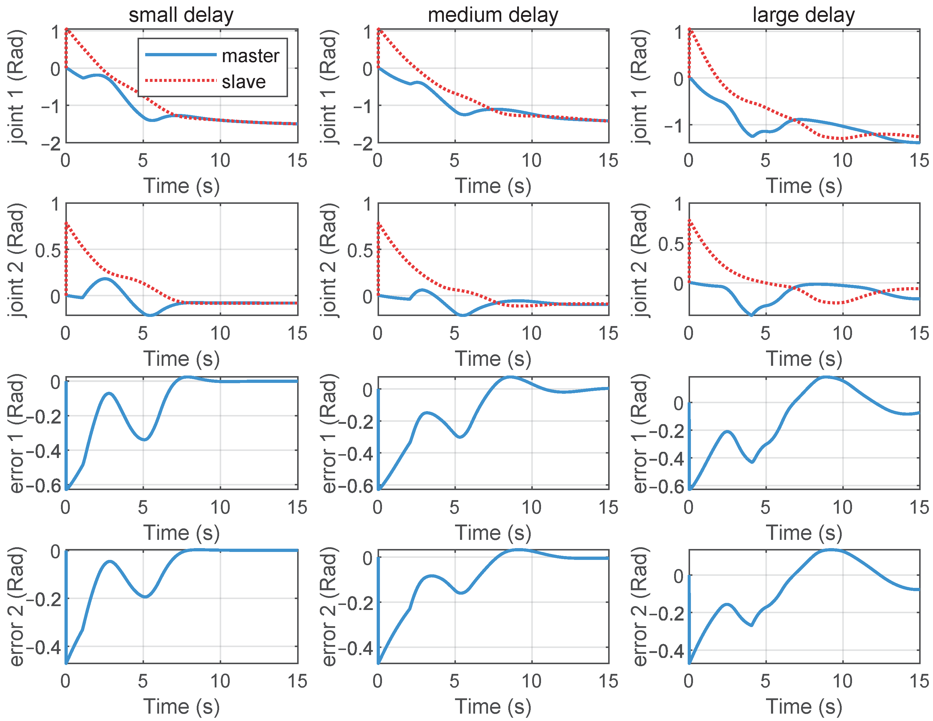
Position tracking performance of the telerobotic system with different communication delays.
Additionally, comparative simulations were conducted with two other control schemes, to illustrate the effectiveness of the proposed method. In Method 1 [31], a proportional damping control law was applied. In Method 2, an adaptive fuzzy PD+damping control approach was designed, which was also applied to compare the tracking performance in telerobotic [37]. In both control methods, the damping coefficients were fixed. In Method 1, the authors assumed that the gravity torque model was known and did not account for the effects of persistent external forces and disturbances. In Method 2, a fuzzy system was employed to compensate for external forces. Consequently, by comparing the position tracking performance of the proposed method with that of Methods 1 and 2, we further analyzed whether the damping parameter adjustment and adaptive strategy presented in this paper exhibited superior performance under conditions of imprecise gravity torque modeling and external force application.
The position synchronization error results are shown in Figure 7 to illustrate the position synchronization control performance of the different methods. Figure 7 presents the position tracking error curves for the three methods. The magnified simulation results demonstrate that, with the proposed method, the position tracking error curves for Joint 1 and Joint 2 entered into a very small neighborhood of zero within 8.5 s and 7.5 s, respectively. In contrast, using Method 1, the tracking error curve for Joint 1 entered into a small neighborhood of zero after 11 s, while the position tracking result for Joint 2 maintained a convergent state throughout the simulation period. There were steady-state errors in the position tracking process. With Method 2, Joint 1 and Joint 2 achieved stability after 11 s and 10 s, respectively, but also exhibited steady-state errors. It is evident that, compared to the proposed method, both Method 1 and Method 2 were less effective in terms of the speed and accuracy of position error convergence. As previously stated, a larger damping gain enhances system stability but also reduces the convergence speed of position errors. For the proposed method, due to the damping adjustment strategy, a larger damping coefficient was provided when the position error is significant. Conversely, when the position error was small, the damping coefficient decreased, thereby accelerating the convergence speed of the position error. In Method 1, uncompensated additional forces resulted in larger steady-state errors. In Method 2, achieving a higher convergence accuracy required setting a larger proportional gain, which required a larger damping coefficient to ensure system stability. Therefore, the parameter settings needed to balance the convergence accuracy and convergence speed. However, compared to the proposed method, the damping coefficients in Methods 1 and 2 were fixed and were not adjusted according to the error magnitude, making it difficult to accelerate the convergence speed. These observations are confirmed by the magnified curves, which show that when the position error converged to a smaller range, the proposed method, with its smaller damping coefficient, could achieve a faster convergence speed. We employed the Root Mean Square Error (RMSE) index to evaluate the convergence speed and accuracy of position synchronous performance under the three control methods. Detailed RMSE data are shown in Table 2.
Table 2.
RMSE index of tracking error under different control methods in simulation experiments.
We also compared the position tracking control performance under different controller gains and , for . Figure 8 shows the position tracking and position error curves of the telerobotic system under different proportional gains . From top to bottom, the subplots in each row represent the position tracking curves for Joint 1 and Joint 2, as well as the tracking error curves for Joint 1 and Joint 2, respectively. The subgraphs from left to right represent the position control results of the medium size , small value , and large value , respectively. From these results, it can be observed that the smaller the , the slower the response speed. The larger the value of , the faster the response speed. But some small oscillations appeared in the position error curves. Figure 9 gives the position tracking performance with different damping gains . The subgraphs from left to right show the position tracking results of the medium , small , and large . From these curves, it can be deduced that the larger the damping gain, the slower the error convergence speed; the smaller the damping gain, the faster the error convergence speed, but position jitter may occur.
The position tracking control performance under different communication delays was also compared. Figure 10 presents the position tracking curves of the telerobotics under different communication delays. When the communication delay increased, oscillations occurred during the position tracking process, but stable convergence could still be achieved.
Once the proportional gain and damping gain are determined, the bounds of the communication delays can be established based on (11). In the simulation, the proportional gains and the damping gains . With the (11), it can be concluded that the communication delay between the master and slave ends should satisfy s. It can be seen that this relationship is conservative based on the simulation results. As shown in the last column of Figure 10, the system still exhibited a stable trend, even when the maximum communication delay reached 5.5 s; however, it can be seen that the stability decreased. Therefore, based on (11), we can select the more conservative communication delays to ensure system stability.
4.2. Experiment Analysis
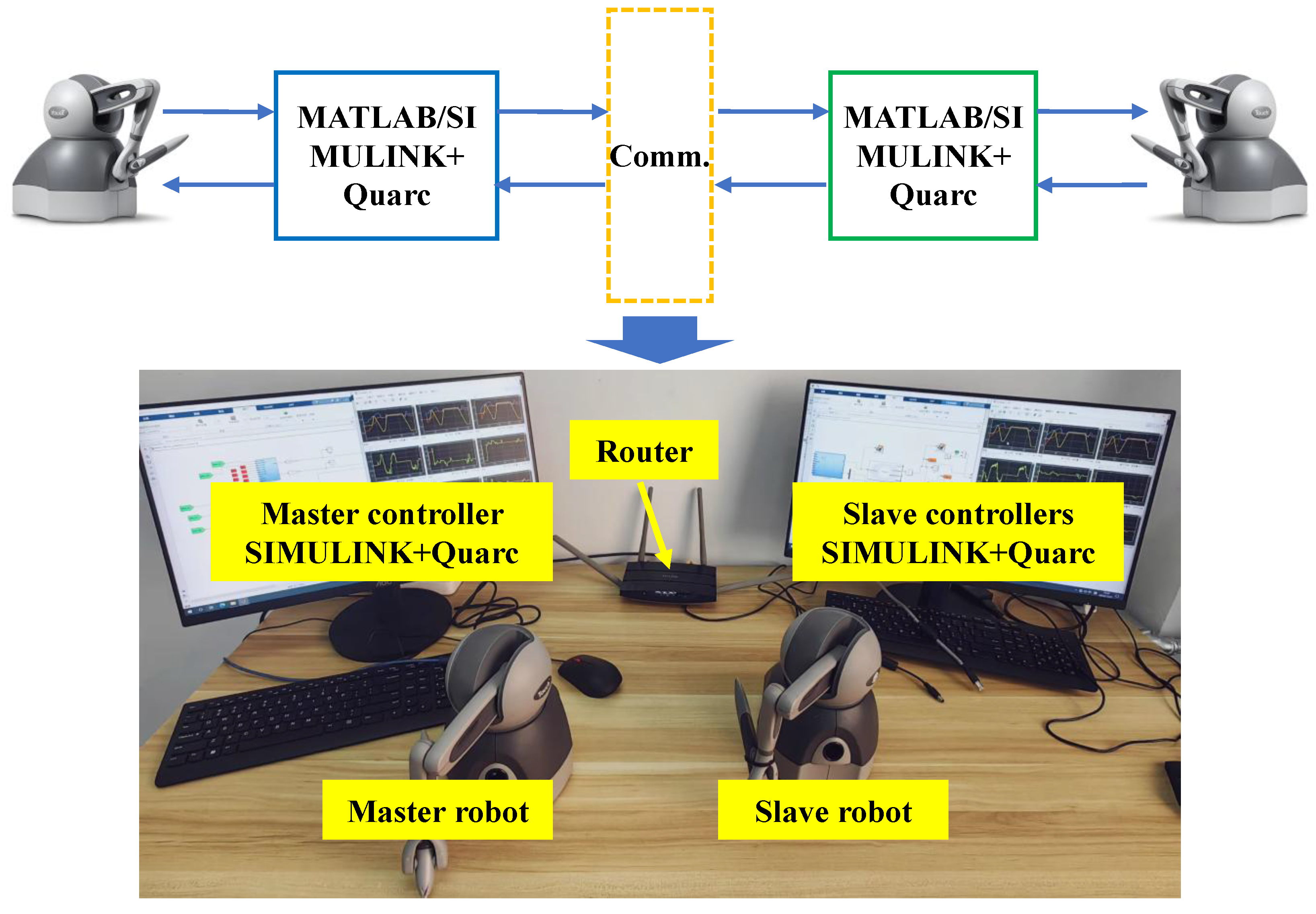
In this part, a position tracking experiment was conducted with a single master and a single slave robot, to validate the proposed control method. Two TOUCH robots (3D Systems, Inc., Rock Hill, JC, USA) were utilized to construct a telerobotic system. Each TOUCH robot had three active degrees of freedom and joint torque control modes. Two computers were employed to serve as the master controller and slave controller. A router was used to establish a communication connection between the master and slave controllers. MATLAB/SIMULINK (MATLAB 2022b, MathWorks Inc., Natick, MA, USA) and Quarc2023 (Quanser, Spy Ct, Markham, ON, Canada) real-time control software were used to drive the TOUCH robots, implement control methods, and collect the result data. The detailed structure of the telerobotic experimental system is shown in Figure 11. In the experiment, simulated communication delays were superimposed with actual communication delays to emulate a more realistic communication delay process. The controllers of the master and slave robots were connected via a router, thereby introducing actual communication delays. However, since the actual delays were relatively small, the “Variable Time Delay” block in Simulink was utilized to simulate larger delays for the experimental purposes. The simulated communication delays in the experiment were defined as and .
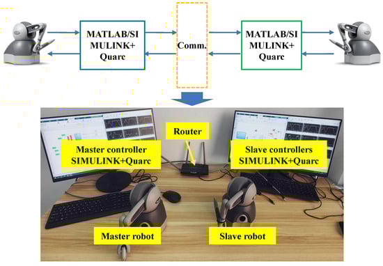
Figure 11.
Composition of telerobotic experimental system.
Figure 11.
Composition of telerobotic experimental system.
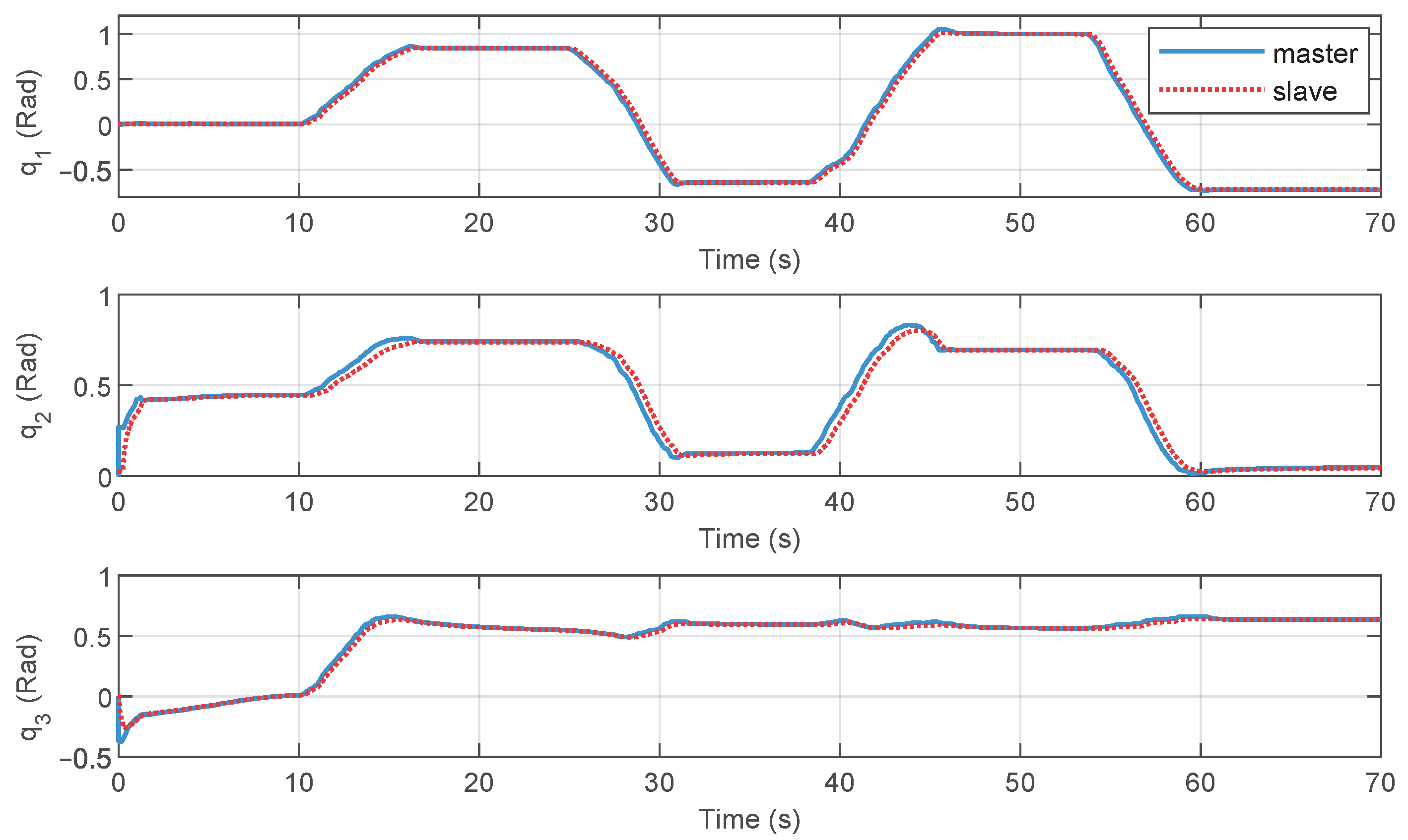
The unit of control torque calculated by the controller is mN. The controller gains were set as , , , , , , . In the experiment, the operator controlled the movement of the master manipulator, and the slave robot followed its motion. When the robot was moved to a special position, the operating force was removed, and both the master and slave robots either remained stationary at the current position or moved freely. Figure 12 illustrates the position tracking of the master and the slave robots. From the experimental results, it is evident that, using the proposed method, the slave TOUCH robot successfully achieved position synchronization control. The position tracking curves prove that the proposed control approach provided stable joint tracking in a time-delayed telerobotic system.
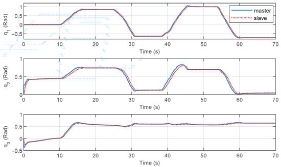
Figure 12.
Joint position tracking with proposed method.
Similarly to for the simulation experiments, a comparative study on the position tracking error performance was conducted for the proposed method, Method 1, and Method 2. Figure 13 presents the comparative curves of the position tracking errors for these three methods. Compared to the results obtained with the proposed method, when the operator applied a force, the position tracking errors based on Method 1 exhibited overshoot and steady-state errors, along with slower convergence rates, such as observed in Joint 1 after 55 s, Joint 2 after 30 s, and Joint 3 after 30 and 60 s. The result curves for Method 2 show less fluctuations but still present steady-state errors and slower convergence speeds. In Method 1, to achieve faster error convergence, the gain weight for the error in the controller was increased, which led to larger position errors during position transitions. This observation is consistent with the experimental results. The RMSE was also employed here to quantify the convergence speed and accuracy of position tracking control under the three control methods. Table 3 presents the RMSE experimental results. From the RMSE index, it can also be seen that the proposed method had lower numerical values, indicating that it had a better control performance.
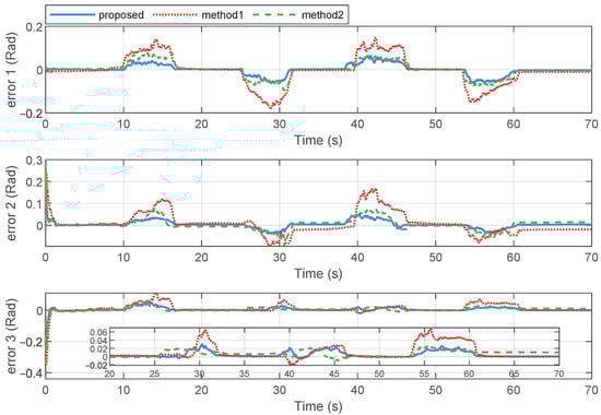
Figure 13.
Joint position tracking comparisons with proposed method, Method 1, and Method 2.
Table 3.
RMSE index of tracking error under different control methods in actual experiments.
5. Conclusions
In this paper, an improved P + d control method was developed to address the stability and position synchronization challenges of time-delay telerobotic systems. A new damping regulator based on the tanh function was introduced into the controller to enhance both the robustness and the response speed. Adaptive controllers were employed to estimate model components and external forces. Using the Lyapunov–Krasovskii method, the boundedness and stability of the system were proved, and the relationship between the upper bound of the communication delay and controller gains was established, providing a basis for selecting appropriate values for constraining the communication delays and controller gains. Finally, the effectiveness of the proposed method was verified through simulation and experimental results. However, in future research, there remains a substantial amount of work to be undertaken and further explored. This includes addressing position tracking control under more complex non-ideal conditions, integrating distributed control architectures with the current teleoperated robotic systems, and investigating the application of reinforcement learning and data-driven methods to compensate for model uncertainties and environmental variations.
Author Contributions
Methodology, L.X., H.Z. and J.L.; stability analysis, L.X. and H.Z.; simulation and experiment, L.X., W.Z. and Y.F.; writing—original draft preparation, L.X.; writing—review and editing, H.Z. and J.L. All authors have read and agreed to the published version of the manuscript.
Funding
This research was funded by Major Special Project of Gansu Academy of Sciences grant number 2023ZDZX-03, National Natural Science Foundation of China grant number 62203196, 62366031, and 62303074, Longyuan Youth Talent Project of Gansu Province, and Hongliu Excellent Youth Fund of Lanzhou University of Technology.
Data Availability Statement
The original contributions presented in this study are included in the article.
Conflicts of Interest
The authors declare no conflicts of interest.
Appendix A
After differentiating with respect to time, the bounding process for the inequality of is derived as
For any and , we have
Therefore, for , it can be further obtained that
With , , for , we have
Then, we can obtain that
Consequently, can be rewritten as follows:
where .
Appendix B
As , , we can obtain that
References
- Hokayem, P.; Spong, M.W. Bilateral teleoperation: An historical survey. Automatica 2006, 42, 2035–2057. [Google Scholar] [CrossRef]
- Alatorre, D.; Nasser, B.; Rabani, A.; Nagy-Sochacki, A.; Dong, X.; Axinte, D.; Kell, J. Teleoperated, in situ repair of an aeroengine: Overcoming the internet latency hurdle. IEEE Robot. Autom. Mag. 2019, 26, 10–20. [Google Scholar] [CrossRef]
- Ghorbanian, A.; Rezaei, S.; Khoogar, A.; Zareinejad, M.; Baghestan, K. A novel control framework for nonlinear time-delayed dualmaster/single-slave teleoperation. ISA Trans. 2013, 52, 268–277. [Google Scholar] [CrossRef]
- Shahbazi, M.; Atashzar, S.F.; Patel, R.V. A systematic review of multilateral teleoperation systems. IEEE Trans. Haptics 2018, 11, 338–356. [Google Scholar] [CrossRef] [PubMed]
- Li, Y.L.; Li, C.X.; Dong, J.; Wang, H.J. Master-slaves synchronization of teleoperation systems with the Try-Once-Discard protocol under event-triggered communication. Asian J. Control, 2024; in press. [Google Scholar] [CrossRef]
- He, W.; Li, Z.J.; Chen, C.L.P. A survey of human-centered intelligent robots: Issues and challenges. IEEE/CAA J. Autom. Sin. 2017, 4, 602–609. [Google Scholar] [CrossRef]
- Nuño, E.; Basañez, L.; Ortega, R. Passivity-based control for bilateral teleoperation—A tutorial. Automatica 2011, 47, 485–495. [Google Scholar] [CrossRef]
- Sun, D.; Naghdy, F.; Du, H.P. Application of wave-variable control to bilateral teleoperation systems: A survey. Annu. Rev. Control 2014, 38, 12–31. [Google Scholar] [CrossRef]
- Jafari, B.H.; Spong, M.W. Passivity-based switching control in teleoperation systems with time-varying communication delay. In Proceedings of the 2017 American Control Conference, Seattle, WA, USA, 24–26 May 2017; pp. 5469–5475. [Google Scholar]
- Chen, Z.; Huang, F.H.; Sun, W.C.; Song, W. An improved wave-varialbe based four-channel control design in bilateral teleoperation system for time-delay compensation. IEEE Access 2018, 6, 12848–12857. [Google Scholar] [CrossRef]
- Al-Wais, S.; Khoo, S.; Lee, T.H.; Shanmugam, L.; Nahavandi, S. Robust H cost guaranteed integral sliding mode control for the synchronization problem of nonlinear tele-operation system with variable time-delay. ISA Trans. 2018, 72, 25–36. [Google Scholar] [CrossRef] [PubMed]
- Chen, Z.; Huang, F.H.; Chen, W.J.; Zhang, J.H.; Sun, W.C.; Chen, J.W.; Gu, J.; Zhu, S.Q. RBFNN-based adaptive sliding mode control design for delayed nonlinear multilateral telerobotic system with cooperative manipulation. IEEE Trans. Ind. Inform. 2020, 16, 1236–1247. [Google Scholar] [CrossRef]
- Kostyukova, O.; Vista, F.P.; Chong, K.T. Design of feedforward and feedback position control for passive bilateral teleoperation with delays. ISA Trans. 2019, 85, 200–213. [Google Scholar] [CrossRef] [PubMed]
- Shen, S.B.; Song, A.G.; Li, H.J.; Li, T. Constrained control for cloud robotic under time delay based on command governor with interval estimation. IEEE Access 2019, 7, 70999–71006. [Google Scholar] [CrossRef]
- Zhang, H.; Song, A.; Li, H.; Chen, D.; Fan, L. Adaptive finite-time control scheme for teleoperation with time-varying delay and uncertainties. IEEE Trans. Syst. Man Cybern. Syst. 2022, 52, 1552–1566. [Google Scholar] [CrossRef]
- Su, S.; Ji, Y. Adaptive time-varying formation control for teleoperation system: A finite-time approach. Int. J. Adapt. Control Signal Process. 2022, 37, 750–770. [Google Scholar] [CrossRef]
- Li, Y.; Yin, Y.; Zhang, D. Adaptive task-space synchronization control of bilateral teleoperation systems with uncertain parameters and communication delays. IEEE Access 2018, 6, 5740–5748. [Google Scholar] [CrossRef]
- Li, Y.; Yin, Y.; Zhang, S.; Dong, J.; Johansson, R. Composite adaptive control for bilateral teleoperation systems without persistency of excitation. J. Frankl. Inst. Eng. Appl. Math. 2020, 357, 773–795. [Google Scholar] [CrossRef]
- Wang, H.Q.; Liu, P.X.; Liu, S.C. Adaptive neural synchronization control for bilateral teleoperation systems with time delay and backlash-like hysteresis. IEEE Trans. Cybern. 2017, 47, 3018–3026. [Google Scholar] [CrossRef] [PubMed]
- Huang, F.H.; Zhang, W.; Chen, Z.; Tang, J.Z.; Song, W.; Zhu, S.Q. RBFNN-based adaptive sliding mode control design for nonlinear bilateral teleoperation system under time-varying delays. IEEE Access 2019, 7, 11905–11912. [Google Scholar] [CrossRef]
- Chen, Z.; Huang, F.H.; Sun, W.C.; Gu, J.; Yao, B. RBF-neural-network-based adaptive robust control for nonlinear bilateral teleoperation manipulators with uncertainty and time delay. IEEE/ASME Trans. Mechatron. 2020, 25, 906–918. [Google Scholar] [CrossRef]
- Kebria, P.M.; Khosravi, A.; Nahavandi, S.; Wu, D.R.; Bello, F. Adaptive type-2 fuzzy neural-network control for teleoperation systems with delay and uncertainties. IEEE Trans. Fuzzy Syst. 2020, 28, 2543–2554. [Google Scholar] [CrossRef]
- Yang, Y.A.; Gan, L.; Chen, Y.H.; Hua, C.C. Adaptive neural network control for flexible telerobotic systems with communication constraints. J. Frankl. Inst. Eng. Appl. Math. 2022, 359, 4751–4775. [Google Scholar] [CrossRef]
- Tan, N.; Yu, P.; Zhang, M.; Li, C.S. Toward unified adaptive teleoperation based on damping ZNN for robot manipulators with unknown kinematics. IEEE Trans. Ind. Electron. 2023, 70, 9227–9236. [Google Scholar] [CrossRef]
- Wang, F.J.; Yu, Y.J.; Li, X.; Luo, J.X.; Zhong, J.M. Adaptive neural network synchronous tracking control for teleoperation robots under event-triggered mechanism. IEEE Robot. Autom. Lett. 2024, 9, 10010–10017. [Google Scholar] [CrossRef]
- Bouteraa, Y.; Alattas, K.A.; Peng, T.R.; Fekih, A.; Rahmani, R.; Mobayen, S. Design of robust adaptive fuzzy control for uncertain bilateral teleoperation systems based on backstepping approach. IET Control Theory Appl. 2023, 17, 800–813. [Google Scholar] [CrossRef]
- Cao, S.J.; Sun, L.; Jiang, J.J.; Zuo, Z.Y. Reinforcement learning-based fixed-time trajectory tracking control for uncertain robotic manipulators with input saturation. IEEE Trans. Neural Netw. Learn. Syst. 2023, 34, 4584–4595. [Google Scholar] [CrossRef] [PubMed]
- Zhang, Y.; Hua, C.C. Composite learning finite-time control of robotic systems with output constraints. IEEE Trans. Ind. Electron. 2023, 70, 1687–1695. [Google Scholar] [CrossRef]
- Zhao, J.; Wang, Z.G.; Lv, Y.F.; Na, J.; Liu, C.Z.; Zhao, Z.L. Data-driven learning for H∞ control of adaptive cruise control systems. IEEE Trans. Veh. Technol. 2023, 73, 18348–18362. [Google Scholar] [CrossRef]
- Zhang, H.C.; Fu, L.Y.; Zhang, A.C. A Novel Adaptive Finite-Time Position Tracking Control Strategy for Teleoperation System with Varying Communication Delays. Mathematics 2023, 11, 1486. [Google Scholar] [CrossRef]
- De Lima, M.V.; Mozelli, L.A.; Neto, A.A.; Souza, F.O. A simple algebraic criterion for stability of bilateral teleoperation systems under time-varying delays. Mech. Syst. Signal Process. 2020, 137, 106217. [Google Scholar] [CrossRef]
- Islam, S.; Liu, X.P.; El-Saddik, A. Teleoperation systems with symmetric and unsymmetric time varying communication delay. IEEE Trans. Instrum. Meas. 2013, 62, 2943–2953. [Google Scholar] [CrossRef]
- Hashemzadeh, F.; Tavakoli, M. Position and force tracking in nonlinear teleoperation systems under varying delays. Robotics 2015, 33, 1003–1016. [Google Scholar] [CrossRef]
- Chan, L.P.; Naghdy, F.; Stirling, D. Position and force tracking for non-linear haptic tele-manipulator under varying delays with an improved extended active observer. Robot. Auton. Syst. 2016, 75, 145–160. [Google Scholar] [CrossRef]
- Ganjefar, S.; Rezaei, S.; Hashemzadeh, F. Position and force tracking in nonlinear teleoperation systems with sandwich linearity in actuators and time-varying delay. Mech. Syst. Signal Process. 2017, 86, 308–324. [Google Scholar] [CrossRef]
- Pourseifi, M.; Rezaei, S. Adaptive control for position and force tracking of uncertain teleoperation with actuators saturation and asymmetric varying time delays. Int. J. Nonlinear Sci. Numer. Simul. 2024, 24, 3113–3132. [Google Scholar] [CrossRef]
- Lu, Z.Y.; Guan, Y.; Wang, N. An adaptive fuzzy control for human-in-the-loop operations with varying communication time delays. IEEE Robot. Autom. Lett. 2022, 7, 5599–5606. [Google Scholar] [CrossRef]
- Yang, Y.; Constantinescu, D.; Shi, Y. Robust four-channel teleoperation through hybrid damping-stiffness adjustment. IEEE Trans. Control. Syst. Technol. 2020, 28, 920–935. [Google Scholar] [CrossRef]
- Sciavicco, L.; Siciliano, B. Modelling and Control of Robot Manipulators; Springer: Berlin/Heidelberg, Germany, 2012. [Google Scholar]
- Hashemzadeh, F.; Hassanzadeh, I.; Tavakoli, M. Teleoperation in the presence of varying time delays and sandwich linearity in actuators. Automatica 2013, 49, 2421–2813. [Google Scholar] [CrossRef]
- Jleilaty, S.; Ammounah, A.; Abdulmalek, G.; Nouveliere, L.; Su, H.; Alfayad, S. Distributed real-time control architecture for electrohydraulic humanoid robots. Robot. Intell. Autom. 2024, 44, 607–620. [Google Scholar] [CrossRef]
- Li, Z.; Xia, Y.; Su, C.Y. Intelligent Networked Teleoperation Control; Springer: Berlin/Heidelberg, Germany, 2015. [Google Scholar]

Disclaimer/Publisher’s Note: The statements, opinions and data contained in all publications are solely those of the individual author(s) and contributor(s) and not of MDPI and/or the editor(s). MDPI and/or the editor(s) disclaim responsibility for any injury to people or property resulting from any ideas, methods, instructions or products referred to in the content. |
© 2025 by the authors. Licensee MDPI, Basel, Switzerland. This article is an open access article distributed under the terms and conditions of the Creative Commons Attribution (CC BY) license (https://creativecommons.org/licenses/by/4.0/).