Article

Curved-Layer Slicing and Continuous Path Planning for Multi-Axis Printing of Fiber-Reinforced Composite Structures

1
State IJR Center of Aerospace Design and Additive Manufacturing, School of Mechanical Engineering, Northwestern Polytechnical University, Xi’an 710072, China
2
Research & Development Institute, Northwestern Polytechnical University in Shenzhen, Sanhang Science & Technology Buliding, No. 45th, Gaoxin South 9th Road, Shenzhen 518063, China
*
Author to whom correspondence should be addressed.
Processes 2025, 13(2), 473; https://doi.org/10.3390/pr13020473
Submission received: 8 January 2025 / Revised: 23 January 2025 / Accepted: 31 January 2025 / Published: 8 February 2025
(This article belongs to the Special Issue Advanced Manufacturing Processes of Composite Materials)

Abstract

:
Fiber-reinforced composite (FRC) additive manufacturing technologies have successfully overcome the limitations of traditional autoclave forming, offering significantly enhanced design freedom. However, one of the remaining key challenges is the planning of continuous printing paths that align with a defined fiber orientation vector field within FRC structures. This paper introduces a comprehensive framework for multi-axis curved-layer printing of 3D FRC parts. First, a novel multi-axis curved-layer slicing method based on deformed space mapping is proposed. This approach ensures that the sliced curved layers are as parallel as possible to the intended fiber orientations, improving the alignment between the printing process and fiber direction. Next, a vector field-driven printing path planning method for each curved layer is developed, which guarantees that the generated printing paths conform to the specified fiber orientations while also ensuring continuous material deposition. Additionally, a new algorithm for generating support structures tailored to curved layers is proposed, preventing material collapse during the printing process. The effectiveness of the proposed slicing method, path planning, and support structure generation are validated through extensive experiments and simulations, demonstrating their potential to significantly improve the performance and versatility of FRC additive manufacturing.

1. Introduction

Additive manufacturing (AM) processes have been applied in many fields due to their superiority over traditional cutting technologies [1]. Fused deposition modeling, also known as FDM, is one of the most widely used AM processes due to its simplicity [2]. Non-metallic materials such as polylactic acid (PLA), nylon, and other materials are heated to a molten state and then extruded from a nozzle to form a designed part. FDM is widely used to make functional parts in small batches, which are challenging to produce with traditional machining. However, parts fabricated by FDM usually have weak mechanical strength, which limits their applications. In recent decades, fiber-reinforced composite (FRC) printing has attracted more and more attention. Short/continuous fibers such as carbon fibers are added to thermoplastic materials and are extruded from the nozzle simultaneously. Powered by multi-axis CNC technologies, this process effectively liberates the process constraints of traditional thermoforming and dramatically improves the degrees of freedom in design [3].
Both material distribution and the fiber spatial orientation should be considered as design variables when designing an FRC part since, together, they determine the anisotropic strength of the part [4]. The printing path should be aligned with the fiber orientation to ensure that the printed part has the designed mechanical strength. The fiber orientation of a part can be designed manually based on experience. For example, the whole strength of a truss structure is usually enhanced if the fiber orientations are designed along the skeleton. To improve the mechanical performance of FRC structures, some theoretical design methods have been proposed. Topology optimization is an effective tool for structural design and has been successfully used to design FRC structures. Smith et al. [5,6] developed a 2D topology optimization method based on the SIMP method, which can collaboratively optimize both the material distribution and the fiber orientation. Li et al. [7] proposed a full-scale topology optimization method that considers structural topology, path continuity, and fiber volume. Additionally, similar research can be found in [8,9,10,11,12]; most of the studies are based on the density method, and sequential or concurrent schemes are proposed to find the optimal topology shape and fiber orientations. Generally, a smooth and continuous fiber orientation vector field is friendly to printing path planning. Many researchers have attempted to improve the manufacturability of the designed parts by applying process constraints. Papapetrou et al. [13] developed a fiber orientation filtering algorithm to ensure the printing path is easy to fabricate. Fernandez et al. [14] developed a level set-based printing path generation method by considering manufacturing process constraints, including developed clearance, overlap, path continuity, and minimum turning radius. Schmidt et al. [15] proposed a sensitivity-driven topology optimization method that can generate continuous smooth fiber trajectories for 3D topology structures.
After designing the fiber orientation, to ensure that the final printed part has the designed anisotropic strength, the printing paths should be aligned with the spatial fiber orientations. Wang et al. [16,17] attempted to improve the structural strength by aligning the printing path along the load transmission path. Chen et al. [18] developed a printing path generation method for continuous FRCs. In their method, a vector field that indicates the fiber orientations is first generated according to the principal stress vector field; then, the iso-curves induced by the vector field are used as the printing paths. Similar printing path generation methods based on stress field can be found in [19,20,21], and although the anisotropic strength can be enhanced by aligning the printing path along the principal stress direction, it is an intuitive method and cannot be proven to be globally optimal. Ichihara and Ueda [22] developed a design framework to improve the toughness of 3D-printed FRC parts, and the phase field-based method was used to determine the printing path.
However, most of the aforementioned printing path planning methods are limited to 2D cases. For 3D FRC parts that are subjected to complex external loads, the fiber spatial orientation varies at different positions and is no longer parallel to the planar slicing layers. To ensure that the printing paths are aligned with the fiber orientation, the printed part should be sliced into curved layers that are parallel to fiber orientations. However, few studies have focused on multi-axis curved-layer printing process planning for 3D FRC structures. Qiu et al. [23] proposed an optimization method for 3D FRC parts; in their model, the part is composed of several components, and the fiber orientations of each component are restricted to a plane. The proposed method enlarges the space for orientation optimization. However, the final part needs to be assembled using several components rather than being fabricated as a whole; thus, the structural stiffness may be weakened. Curved-layer slicing methods together with multi-axis printing machines make it possible to fabricate an FRC structure with complex fiber orientations. Fang et al. [24,25,26] developed a curved-layer slicing optimization framework for multi-axis printing, mechanical strength, support-free printing, and surface quality, and many other factors are combined as an optimization objective to optimize curved layers and printing path.
Moreover, path continuity is of great importance to both printing quality and efficiency since frequent nozzle jumps may lead to printing defects and a long path. Algorithms that can achieve geometry continuity of the printing path have been developed [27,28,29,30,31]. However, these studies only consider the printing path continuity without optimizing the structural strength. Huang et al. [32] used the topology optimization method to plan a continuous path for continuous fiber-reinforced composites. The authors [33] developed a method that considers both the path continuity and the anisotropic strength. However, the generated continuous path contains many sharp turns, which might not be suitable for printing continuous fiber composites.
This paper mainly focuses on solving this problem by addressing the following question: given an FRC structure with a defined fiber orientation vector field, how can we plan curved-layer printing paths and ensure the paths are aligned with the fiber orientations as much as possible? In addition, the printing path should also be continuous as much as possible to improve printing efficiency and quality. Our main contribution includes a curved-layer slicing method that enables the generated curved layers to be parallel to the fiber orientations, as well as a continuous printing path planning algorithm that can not only align the paths along the fiber orientation but also generate a single-stroke printing path. The rest of the paper is organized as follows: Section 2 presents the multi-axis printing process planning for FRC parts. Section 3 gives ample examples of both experiments and simulations to validate the effectiveness of the proposed curved-layer slicing and printing path planning methods. Finally, Section 4 presents the conclusion.

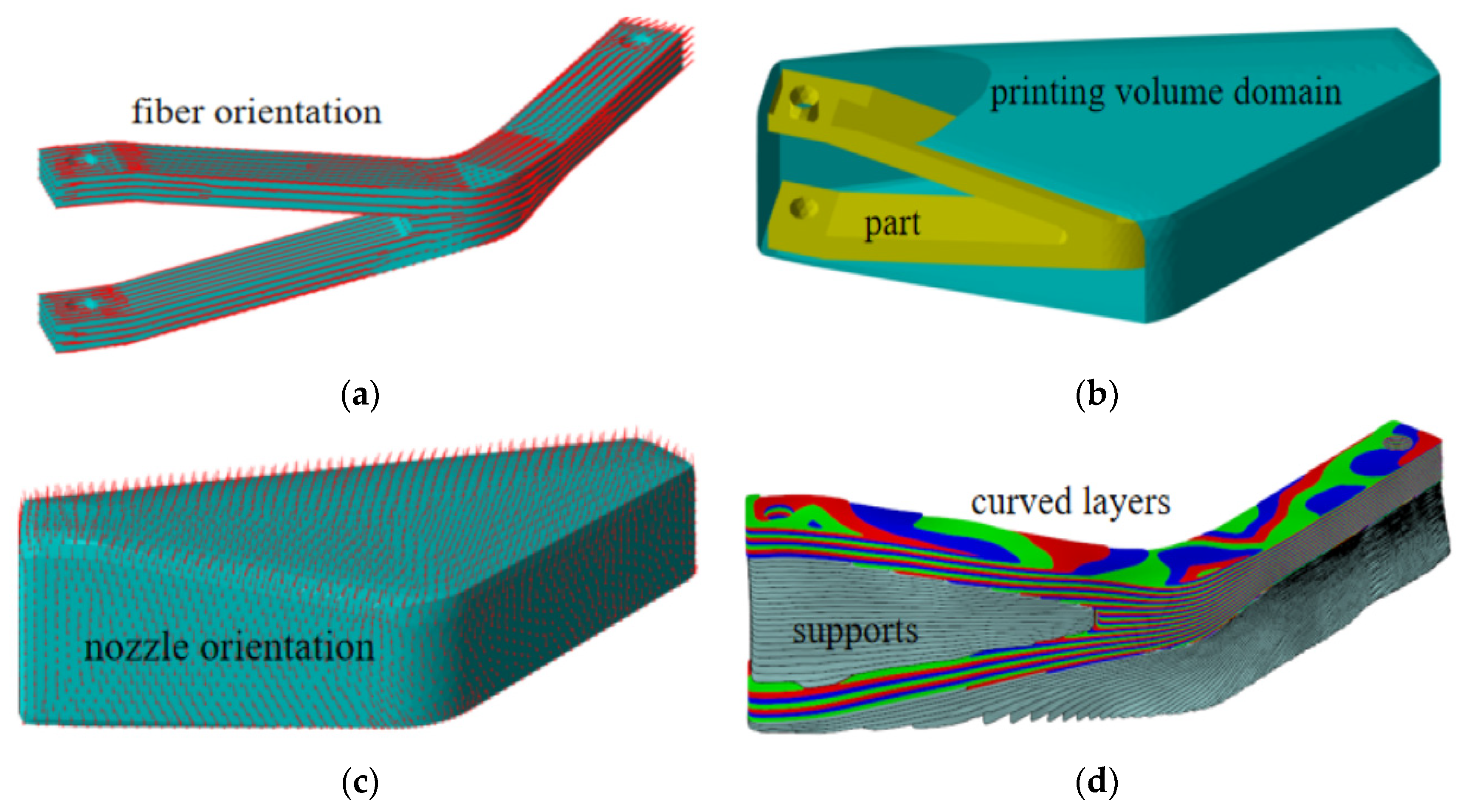
2. Multi-Axis Printing Process Planning for FRC Structures

Figure 1 shows the process planning steps for multi-axis printing of an FRC structure. FRC structures exhibit strong anisotropic strength due to the spatial orientation of fibers; thus, both the topology shape and the fiber orientation should be considered as design variables, which determine the mechanical strength of the structure. Given a part to be printed, a vector field that indicates the spatial fiber orientation should be designed first, as shown in Figure 1a. Then, to facilitate process planning, a volume domain that contains the printed part is defined, and all the curved sliced layers, support structures, and printing paths are generated in this domain (see Figure 1b). To ensure that the final part has the designed mechanical strength, the printing path should be aligned along the fiber orientation vector field (FOVF), and the part needs to be sliced into curved layers parallel to the FOVF. To achieve this goal, another vector field that indicates the nozzle orientation during the printing process is generated in the printing volume domain, and the nozzle orientations should be orthogonal to the FOVF (see Figure 1c). Then, several curved layers perpendicular to the nozzle orientation vector field (NOVF) are found, and support structures for curved layer printing are also generated (see Figure 1d). At each curved layer, the printing paths are planned along the projection vectors of the FOVF. The details of the proposed method are given in Section 2.1, Section 2.2, Section 2.3 and Section 2.4.

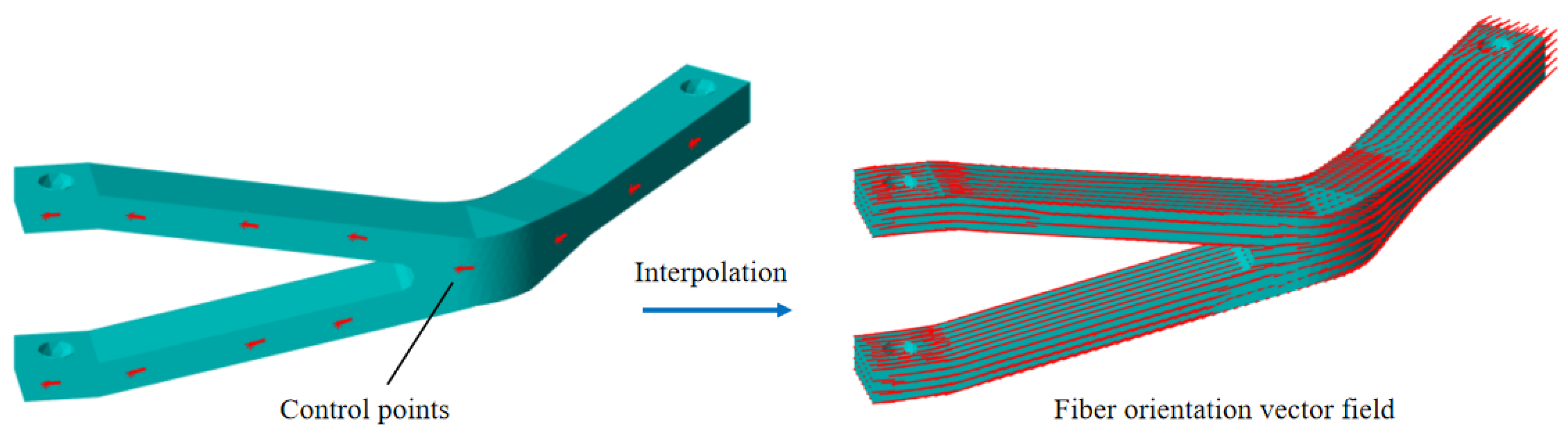
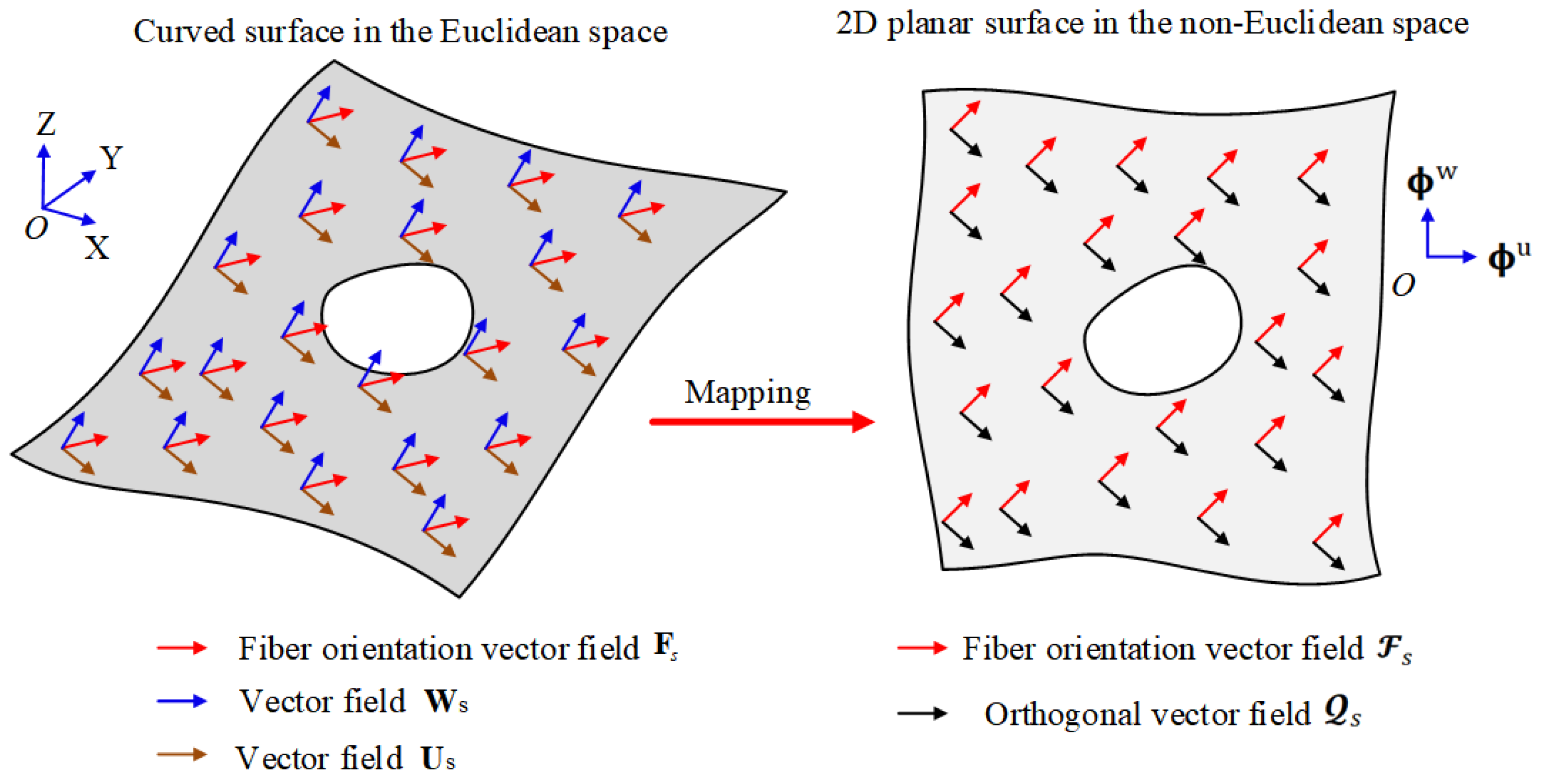
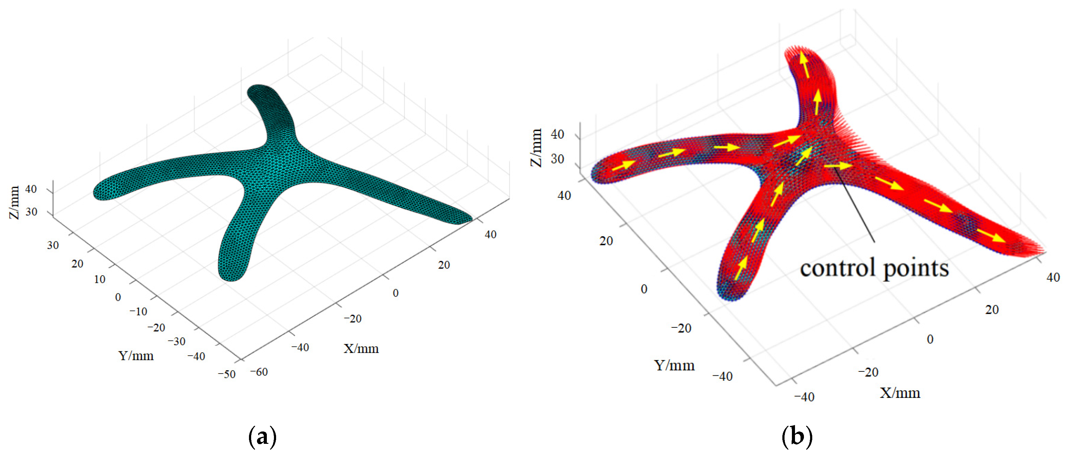
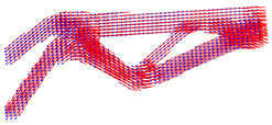
2.1. Generation of the Fiber Orientation Vector Field

The final designed part can be represented by a tetrahedral mesh M p V ,   T , where V and T are the collections of vertices and tetrahedrons. The FOVF embedded on the part M p can be generated manually. Let us first select several vertices at the boundary of the part as the control points, as shown in Figure 2, and the fiber orientation at these control points can be defined manually. An interactive software tool can be designed to let the user set the fiber orientation freely at the control point according to their experience. Then, the FOVF F p at the entire mesh M p can be obtained by interpolation. Assuming f i is the vector of F p at the ith vertex, it can be calculated by
f i = k = 1 m 1 l k v k k = 1 m 1 l k
where v k is the defined vector at the kth control point, l k is the distance between the kth control point and the ith vertex, and m is the number of control points. Generally, for a part that has many slender beams, the structure strength would be enhanced if fiber orientation vectors were aligned along the beams.
In addition to the above manual method, the FOVF can also be generated automatically by topology optimization. In this paper, the following topology optimization model is used to obtain the optimal FRC structures:
m i n :   c ρ , α , θ = U ρ , α , θ T F s t : v ρ V 0 = f K ρ , α , θ U ρ , α , θ = F ρ m i n ρ e 1 2 π α e 2 π π 2 θ e π 2
where ρ = [ ρ 1 , ρ 2 , , ρ N ] represents the element density design variables, while α = [ α 1 , α 2 , , α N ] and θ = [ θ 1 , θ 2 , , θ N ] are fiber orientation angle variables, where N is the number of elements. The compliance c ρ , α , θ is set as the objective function, which is written as the product of the displacement vector U ρ , α , θ and the external force vector F . The optimization model satisfies the volume constraint v ρ V 0 = f , where v ρ is the design volume, V 0 is the original volume of the design domain, and f (0 < f < 1) is the prescribed volume fraction. The second constraint is the static equilibrium equation, where K ρ , α , θ is the total stiffness matrix. A detailed description of this model can be found in [15]. Figure 3 shows an example of topology optimization of an FRC structure; the design domain (20 mm × 20 mm × 80 mm) and the boundary condition are shown in Figure 3a. As accurately modeling the FRCs is out of the scope of this paper, we use linear elastic assumption to approximately predict the mechanical behavior of the FRC parts. The homogenization method is employed to calculate the elastic matrix DH of the anisotropic material, which is then used in topology optimization and finite element analysis, as shown in Figure 3b. The final optimized topology structure and the FOVF are shown in Figure 3c,d, respectively.

2.2. Generation of the Nozzle Orientation Vector Field

Now, we have a printed part M p V ,   T and a FOVF F p embedded on M p . The printing paths should be planned along the FOVF to ensure that the final part has the designed mechanical strength. To facilitate printing path planning, a volume domain that contains the entire printed part mesh is defined, where the printing paths and the support structures are all generated in this domain. The convex hull of the printed part can be used as the printing volume domain, and the bottom of the volume domain should be flat, as shown in Figure 1.
The printing volume domain is then discretized into a tetrahedron mesh M v ( V m , T m ) . The FOVF F p at M p is smoothly spread to the entire printing volume domain M v to obtain a vector field F v embedded on the mesh vertices by interpolation; this vector field is called FOVF in the rest of the paper, as shown in Figure 4a.
To ensure that the printed part has the designed anisotropic property, the printing path should be aligned with the FOVF F v . To achieve this goal, the part can first be sliced into curved layers that are parallel to the FOVF F v . Then, at each curved slicing surface, the printing paths should be planned along the FOVF F v as the nozzle axis orientation continuously changes during the multi-axis printing process. A unit vector field P v called the nozzle orientation vector field (NOVF) that is orthogonal to the FOVF F v can be obtained by solving the following optimization problem:
Find   P v = θ 1 p , θ 2 p , θ i p , , θ n p ; φ 1 p , φ 2 p , , φ i p , φ n p arg   min i = 1 n f i · p i + s i
where f i and p i are vectors of F v and P v at the ith vertex, respectively. θ i p , φ i p are angle coordinates of p i . n is the number of vertices. s i evaluates the alignment of vectors at the neighborhood sphere of the ith vertex and can be written as
s i = j = 1 m θ j p θ i p 2 + φ j p φ i p 2
where m is the number of vectors in the neighborhood sphere. The optimization model in Equation (3) can be solved by using some gradient algorithms with sensitivities calculated by the difference method, as shown in Figure 4b.

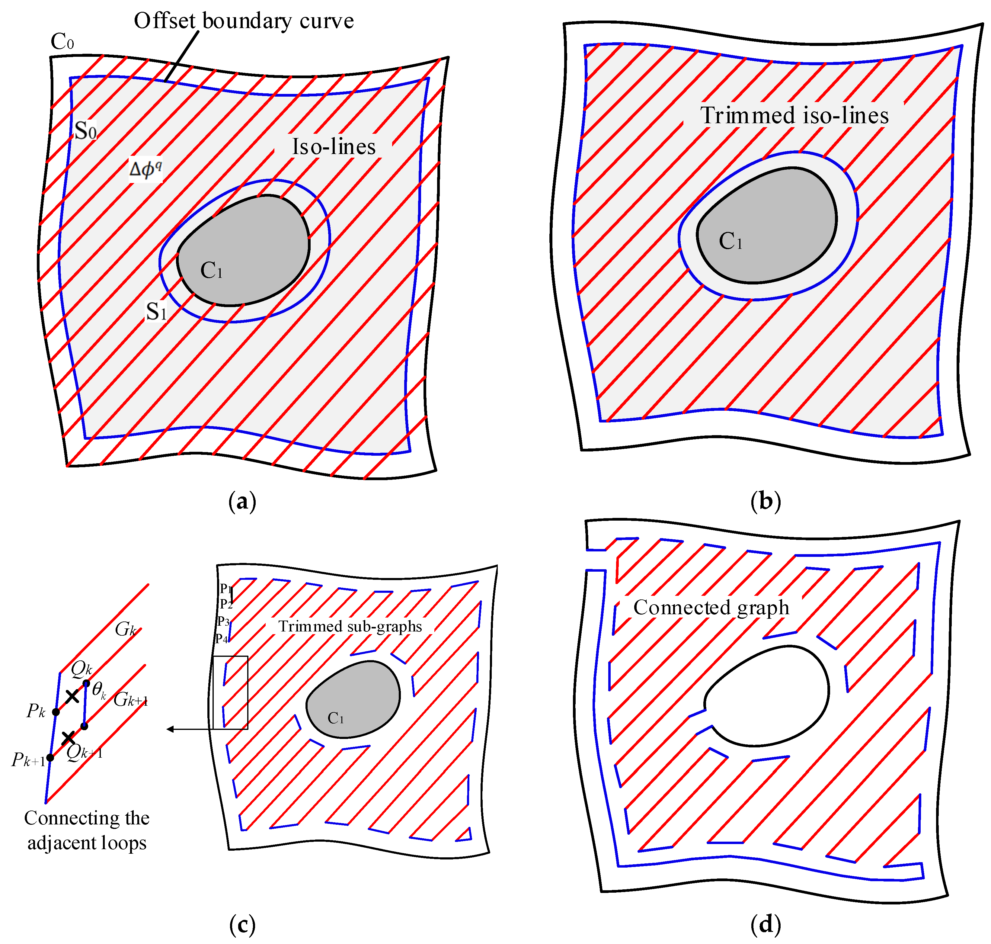
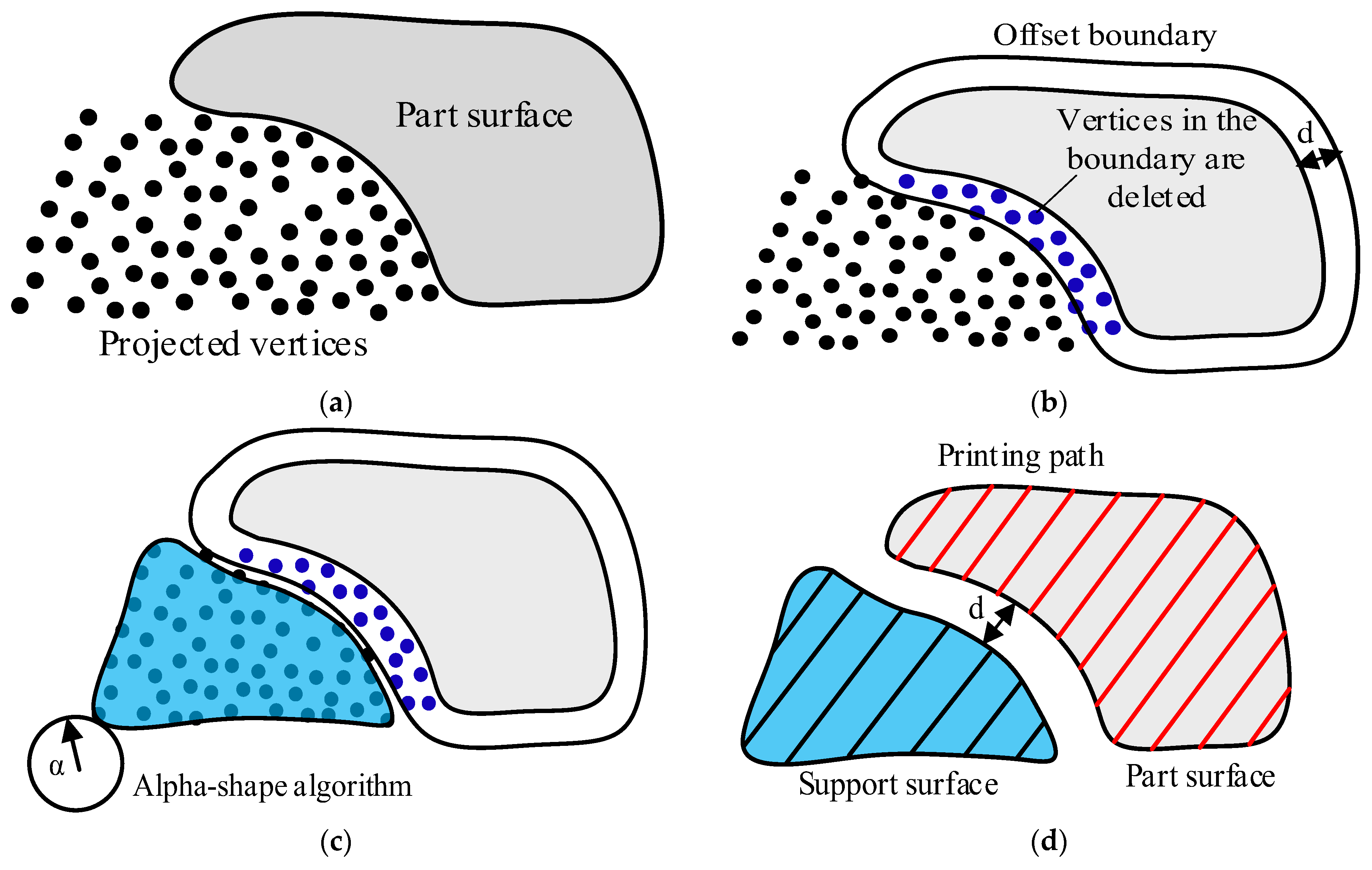
2.3. Adaptive Curved-Layer Slicing Method

The NOVF P v generated in Section 2.2 can be used to control the shape of curved sliced layers. Namely, the part can be decomposed by curved surfaces that are perpendicular to the NOVF P v . To facilitate the curved-layer slicing, let us define another two vector fields W v and U v , and W v , U v , and P v are mutually orthogonal with each other. The ith vectors ( w i and u i ) of W v and U v can be calculated by
s i = j = 1 m θ j p θ i p 2 + φ j p φ i p 2
where the reference vector r can usually be set to (1, 0, 0).
A few curved surfaces that are perpendicular to P v and parallel to F v can be found to decompose the part into curved layers. This is equivalent to finding a scalar field ϕ p , whose gradient ϕ p is parallel to P v . Then, the iso-surfaces of ϕ p can be used to decompose the part into curved layers, and ϕ p can be obtained by solving the following optimization problem:
F i n d   ϕ p ( ϕ 1 p , ϕ 2 p , ϕ n p )   a n d   R p ( r 1 p , r 2 p , r m p ) a r g   m i n i = 1 m ϕ i p r i p p i
where ϕ i p and p i are the gradient vector of scalar value and the printing orientation at the ith tetrahedron, respectively; r i p is the weight of p i ; and n and m are the number of vertices and tetrahedrons, respectively. The above non-linear optimization problem is actually equivalent to solving the Poisson equation.
ϕ p = d i v ( r 1 p p 1 , r 2 p p 2 , r m p p m )
which can be written as the following matrix:
A 3 m × ( m + n ) ϕ 1 p ,         ϕ 2 p , , ϕ n p , r 1 p , r 2 p , , r m p = 0
where A is a sparse matrix of 3m × (m + n) that contains all the coefficients of the equations. As 3m > ( m + n ) , an exact solution to Equation (6) does not exist. In this paper, a heuristic algorithm is proposed to approximately find both ϕ p and R p , as shown in Algorithm 1; the algorithm contains an iteration loop. At each iteration, the Poisson equation Δ ϕ ~ = · P ~ is solved to find an intermediate ϕ ~ , and R p is estimated by ϕ ~ . Then, P ~ is modified by p ~ i = r i p p i / r p ¯ for the next iteration, where r p ¯ is the mean of ( r 1 p , r 2 p , r m p ) . The angle error θ i is defined as the included angle between ϕ ~ i and p i . The loop stops when the mean angle error is no longer decreasing. Figure 5a,b show the curved sliced layers of the printing volume and the printed part, respectively. The nozzle orientation error θ i at the ith tetrahedron is defined as the included angle between ϕ i p and p i . Figure 6a shows the iteration curve of Algorithm 1; after 14 iterations, the mean nozzle orientation error finally converges to 4.58°. Figure 6b shows the histogram of the nozzle orientation errors, which means that the sliced curved layers are approximately perpendicular to the NOVF P v . However, due to the nature of Equation (7), the nozzle orientation error cannot be totally eliminated.
Algorithm 1. Calculation of the scalar field ϕ p of P.
Input: the orientation vector field P embedded on the tetrahedral mesh M v ( V m , T m )
1 P ~ = P
2 Solve the Poisson equation Δ ϕ ~ = · P ~ and obtain the scalar field ϕ ~
3 Calculate the gradient vector field ϕ ~ of ϕ ~
4 Let r i p = ϕ ~ i . Calculate r p ¯ = m e a n ( r 1 p , r 2 p , r m p ) , and let p ~ i = r i p p i / r p ¯
5 Calculate the angle error θ i between ϕ ~ i and p i , and let θ ¯ = m e a n ( θ 1 , θ 2 , θ m )
6 if θ ¯ is no longer decreasing  then
7    ϕ p = ϕ ~
8 else
9   go to line 2
10 end
Another two scalar distance fields, ϕ w and ϕ u , induced by the vector field W v and U v , can also be calculated by solving Equation (6). The three mutually orthogonal distance scalar fields ( ϕ w , ϕ u , and ϕ p ) generate a deformed space χ , and there exists a mapping between the deformed space χ and the Euclidean space, as shown in Figure 7. For any point p n in the deformed space χ , a mapped counterpart point p e in the Euclidean space can be found. The nearest tetrahedron t i to p n or p e can be found by using the kd-tree searching algorithm, assuming the coordinates of the vertices of t i in the Euclidean space and the deformed space are v k e and v k n , respectively. Then, p n or p e can be calculated by
p n = k = 1 4 w k n v k n p e = k = 1 4 w k e v k e
where w k n and w k e are volume weights; for example, w 1 n and w 1 e can be given by
w 1 n = V ( p e , v 2 e , v 3 e , v 4 e ) V ( v 1 e , v 2 e , v 3 e , v 4 e ) w 1 e = V ( p n , v 2 n , v 3 n , v 4 n ) V ( v 1 n , v 2 n , v 3 n , v 4 n )
Based on the mapping of Equation (9), the planar surfaces that are perpendicular to the P axis in the deformed space χ can be mapped to the curved surfaces that are perpendicular to the NOVF P v in the Euclidean space. Therefore, we can plan the printing paths in the deformed space χ in the manner of three-axis printing and obtain the real paths for multi-axis printing by the mapping process.
The layer thickness is no longer uniform for each curved layer. Thus, the distance for every two adjacent planar surfaces in the deformed space χ should be adjusted to ensure that the maximum Euclidean distance between the two curved surfaces is smaller than a prescribed value. An adaptive slicing algorithm is proposed to control the thickness of the curved layers. As shown in Figure 8, for the ith p-surface of ϕ i p in the Euclidean space, several sampling points are first planned and offset along their normal directions with a distance d. These offset points are mapped to the deformed space. Then, the minimum p-value ϕ i + 1 p of the mapped points can be used to interpolate the next curved layer, and the maximum Euclidean distance between the two surfaces will be the offset distance d.

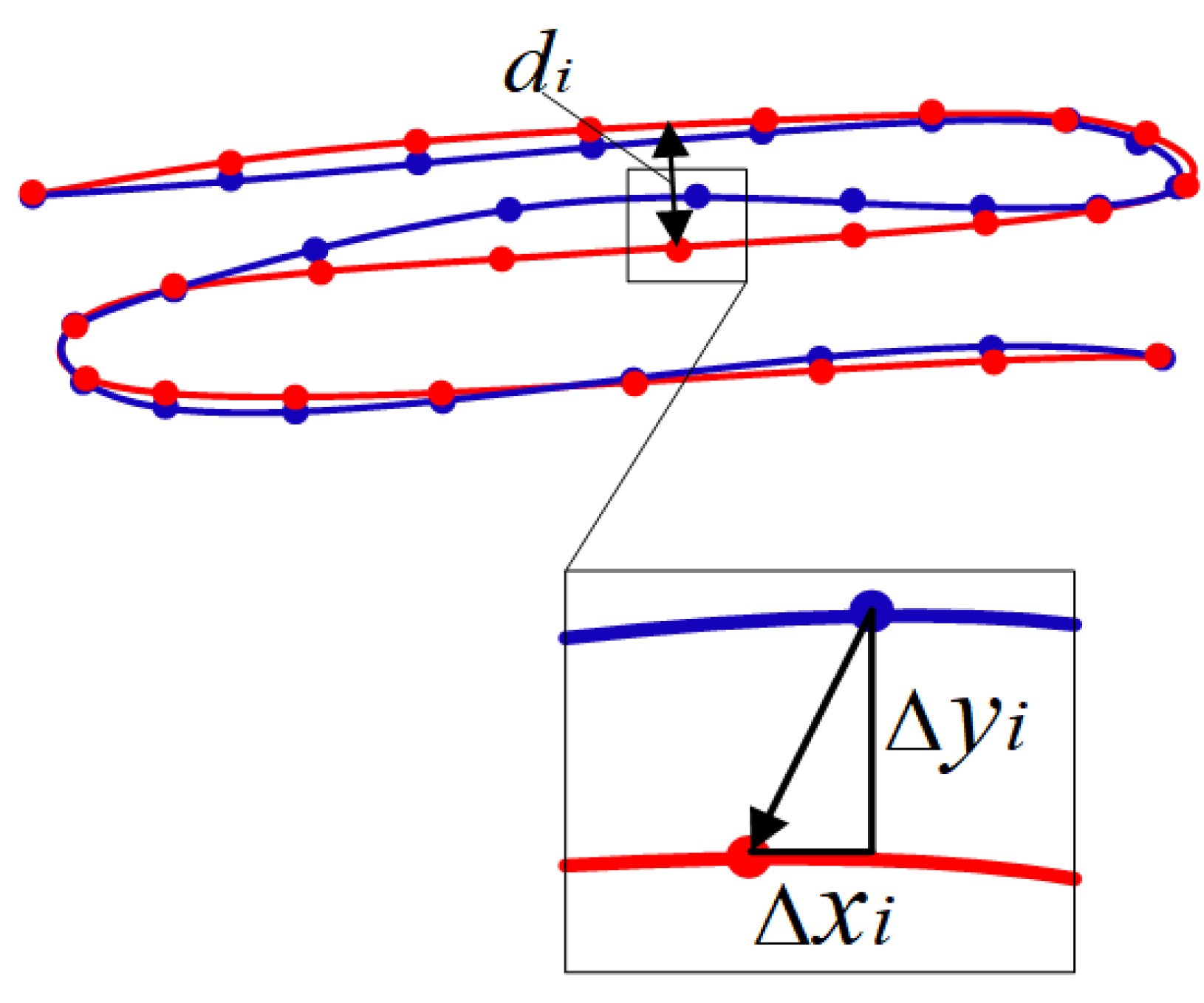
2.4. Vector Field-Driven Path Planning Method

A number of curved surfaces that are approximately parallel to the FOVF F can be obtained by using the curved-layer slicing method, and each curved surface can be represented by triangular mesh M s ( V s , F s ) , where V s and F s are the collections of vertices and triangle faces, respectively. As the curved surface is embedded in the FOVF F v , a vector field F s that indicates the fiber orientation at the curved surface can be obtained by interpolation. A path planning method that can not only align the path along the vector field F s but also ensure that the final path is a single-stroke continuous path.
As discussed in Section 2.3, the curved surface in the Euclidean space can be mapped to a 2D planar surface in the deformed space χ , and the fiber orientation vector field F s can also be mapped to F s at the 2D planar surface. To avoid some geometry problems at the curved surface, the continuous printing path is planned at the 2D planar surface in the deformed space χ , and the real multi-axis printing path at the curved surface can be obtained by the inverse mapping process. As shown in Figure 9, at the 2D planar surface, F s is rotated around the surface normal vector (0, 0, 1) by 90° to obtain a new vector field Q s . A scalar field ϕ q induced by the vector field Q s ( q 1 , q 2 , q i q m ) can be found by solving the following optimization problem defined on the triangular mesh of the 2D surface:
F i n d   ϕ q ( ϕ 1 q , ϕ 2 q , ϕ n q )                     a r g   m i n   i = 1 m ϕ i q q i
where ϕ i q is the gradient of scalar values at the ith triangular face and m is the number of triangular faces. The iso-lines of ϕ q are approximately parallel to F s .
An algorithm is developed to connect the interpolated iso-lines to a Eulerian graph that must contain a continuous path. As shown in Figure 10a, the iso-lines of the scalar distance field ϕ q are first interpolated and the sampling interval is Δ ϕ q . The boundary contours (C0, C1, C2, …) of the region are offset inward with a distance of Δ ϕ q to obtain offset contours (S0, S1, S2, …). Then, the iso-lines are trimmed by the offset contours to form an undirected graph, as shown in Figure 10b. For each offset contour Si, all the intersection vertices along Si are numbered one by one (1, 2, 3, …, 2n). Then, by deleting all the edges between vertices P2k−1 and P2k (k = 1, 2, 3, …), the degree of each vertex becomes 2, as shown in Figure 10c. The trimmed graph contains several connected Eulerian sub-graphs, which can be identified by using the Depth-First Search algorithm. These sub-graphs should be connected without increasing the degree of the vertices. For every two adjacent sub-graphs that contain the intersection vertices Pk and Pk+1, two vertices Qk and Qk+1 on the path edges that are connected to Pk and Pk+1 are built, and the distance Lk between Pk and Qk can be calculated by L k = Δ ϕ q / s i n θ k , where θ k is the included angle between the boundary edge and the path edge. Finally, the two adjacent sub-graphs can be joined by connecting Pk to Pk+1 and Qk to Qk+1 and by deleting edges PkQk and Pk+1Qk+1. A connected graph can be formed by connecting all the adjacent sub-graphs, as shown in Figure 10d, and a totally continuous printing path can be obtained by using the classical Fleury algorithm to traverse the connected Eulerian graph.
The continuous printing path is then further optimized to ensure that the path intervals at any place are approximately equal. The optimization model shown in Equation (10) is used to optimize the path interval:
F i n d   ϕ q ( ϕ 1 q , ϕ 2 q , ϕ n q )                     a r g   m i n   i = 1 m ϕ i q q i
where x i , y i is the deviation of the ith path point, as shown in Figure 11, d i is the ith path interval, and d is the expected path interval. After optimizing the path interval and smoothing the printing path, the path planned at the 2D planar surface is mapped back to the Euclidean space for multi-axis curved surface printing.

2.5. Vector Field-Driven Path Planning Method

Support structures must be needed when printing parts with overhang features. In this section, a support structure generation method for curved-layer slicing is proposed. In the deformed space χ , the support regions of the printed part can be identified by the overhang angle (the included angle between the surface normal direction and the z-axis (0, 0, 1)). As shown in Figure 12, the vertices whose overhang angle is larger than the critical angle (usually 135°) are marked in blue, and support structures are needed at these regions; let us name the set of vertices as ψ . Then, the support region at the ith p-plane of ϕ i p can be obtained by projecting the vertices in ψ that are above the p-plane, and the projected points that are outside the printing volume domain and inside the printed mesh should be deleted. To ensure the shape accuracy of the support surfaces, the face length of the triangular mesh of the part should be smaller than the path interval.
Figure 13 shows the generation steps of the support surface at the ith p-plane of ϕ i p in the deformed space χ . The projected vertices are usually very close to the part surfaces (see Figure 13a). To avoid overlap of support paths and part paths, the boundary of the part surface is offset outward with a distance of d (d can be set as the printing path interval). The projected vertices inside the offset boundary are deleted, as shown in Figure 13b. The alpha-shape algorithm [34,35] is then used to find the contour of the projected points set, as well as the 2D triangular mesh (see Figure 13c), and the alpha value can be set to the path interval. The sliced planar surfaces of the support structure are shown in Figure 14a. Finally, the curved sliced surfaces of the support structure in the Euclidean space can be obtained by the inverse mapping process, as shown in Figure 14b.

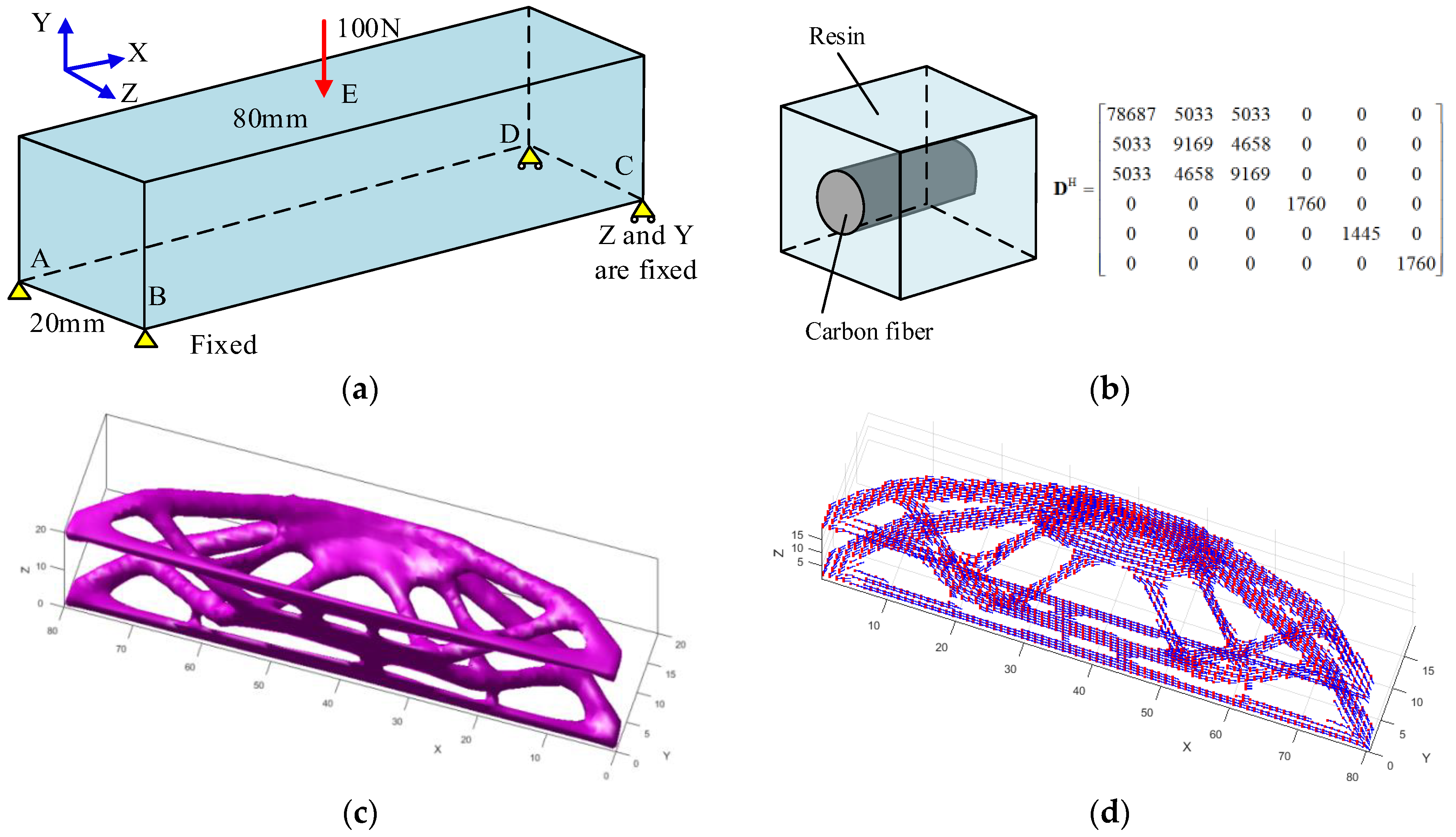
3. Experiment and Discussion

The proposed multi-axis printing process planning method was implemented in C++ and run on a desktop with an Intel i7 CPU. Figure 15 shows our homemade five-axis double-nozzle 3D printer. Section 3.1 uses two examples to validate the vector field-driven continuous printing path planning algorithm. In Section 3.2, four FRC structures with defined FOVFs are shown to be successfully printed using our curved-layer slicing and support generation methods. The printing parameters are shown in Table 1.

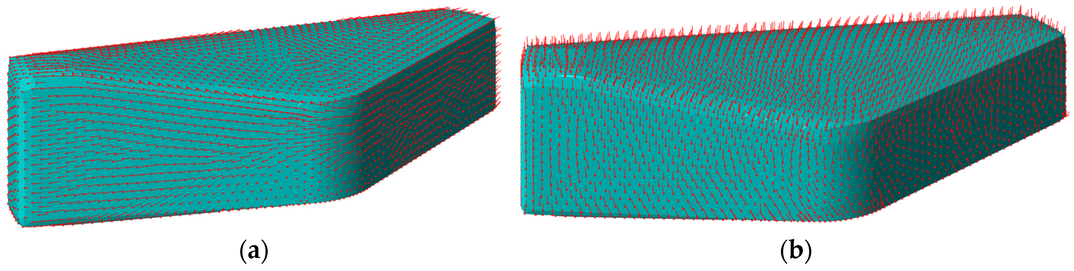
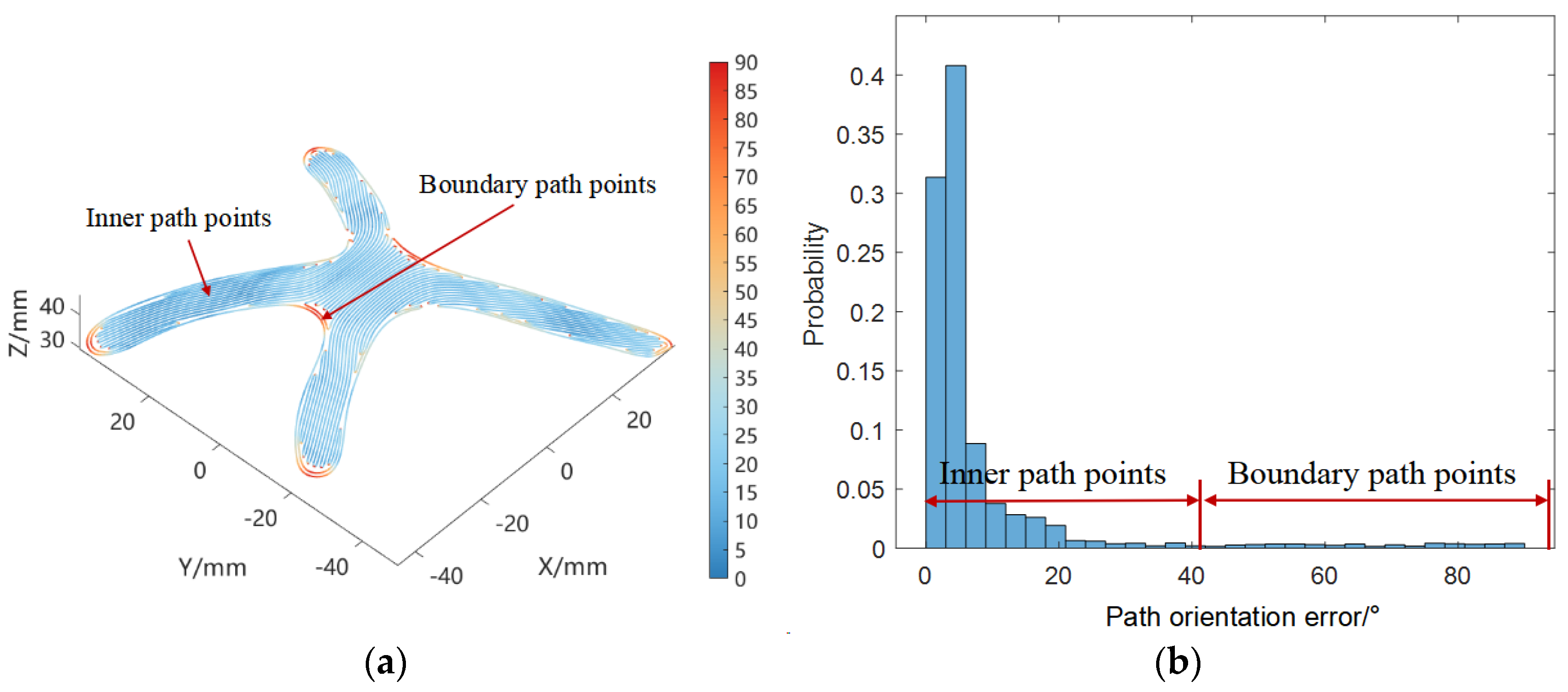
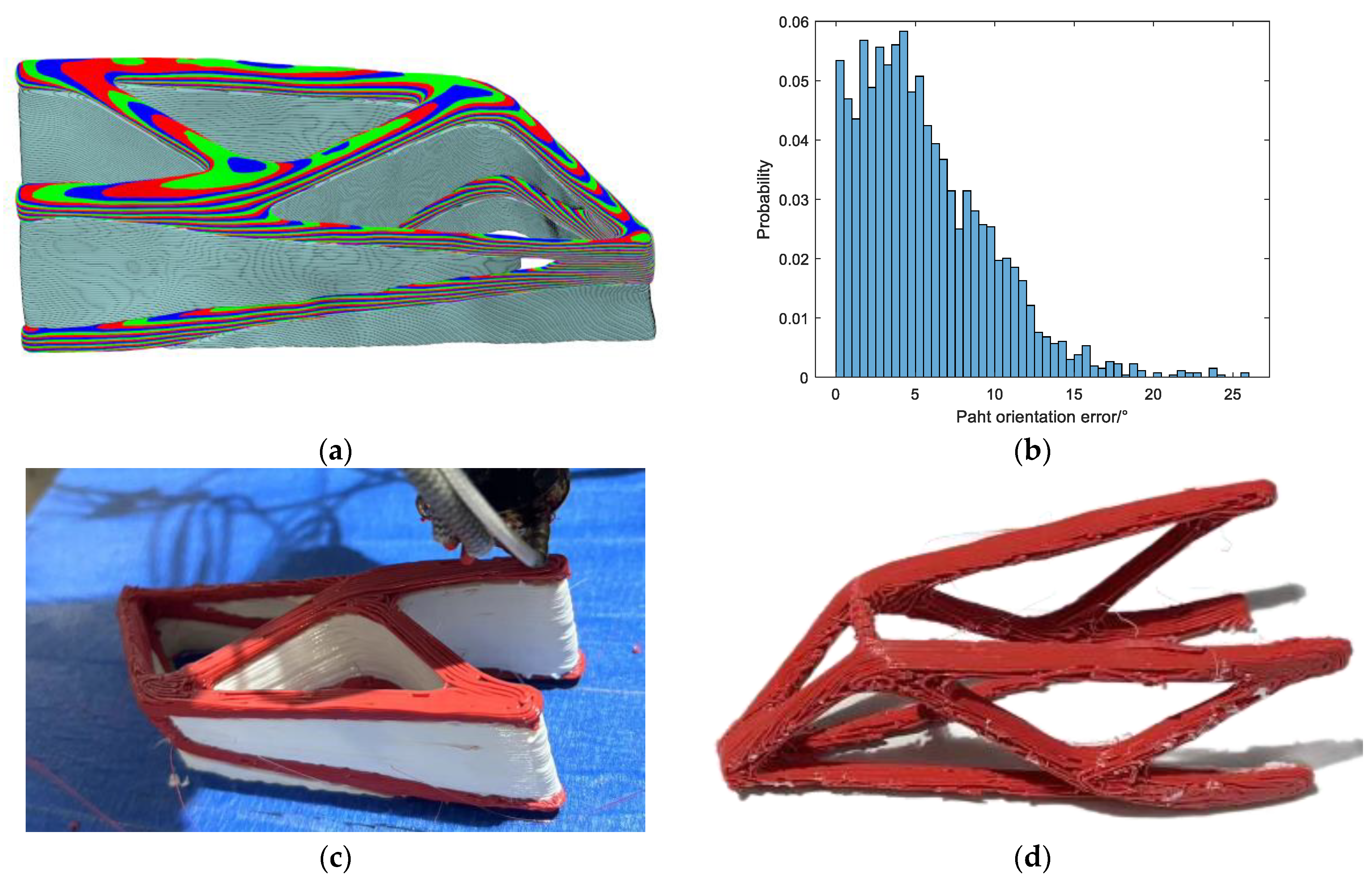
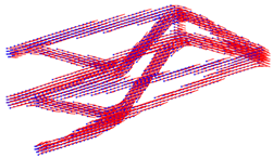
3.1. Vector Field-Driven Continuous Path Planning

Figure 16a shows the triangular mesh of a curved surface; the number of vertices and faces are 2341 and 4278, respectively. A few vertices are chosen as the control points, and the vectors at the control points can be planned manually, usually along the skeleton of the curved surface; then, the vector field on the entire surface can be calculated by Equation (3), as shown in Figure 16b. The path planning method proposed in Section 2.4 is used to generate a continuous path that is aligned with the defined vector field. Figure 17a shows the planned path without optimizing the path interval. It can be found that the printing paths are very close at certain places, which may lead to material redundancy. The printing path interval is then optimized by solving the optimization problem in Equation (10). Figure 18 shows the iteration curve of the optimization; it can be seen that the objective function quickly converges to a constant after 5 steps. The final optimized printing path is shown in Figure 17b; it can be found that the path overlap is effectively reduced, and the path interval is a constant. The path optimization algorithm adjusts the path intervals to avoid narrow clearances between adjacent paths. After optimization, the total path is smoothed using the Laplacian smoothing method. However, this process may lead to shrinkage at sharp 180° turns as the smoothing tends to reduce the size of these corners. This is a limitation of our method. One possible solution to this problem is to use a more advanced smoothing algorithm that better handles shrinkage at 180° turns.
At each path point, the path orientation error is defined as the included angle between the path orientation and the defined vector. Figure 19a shows the path orientation error at different places, and Figure 19b shows the histogram of the path orientation error. The boundary path mainly plays a role in shape preservation, and large path orientation errors can be found at the boundary path. The inner printing paths are formed by iso-lines of the scalar field induced by the defined vector field; they are approximately aligned with the vector field, and the mean path orientation error is 5.07°. The path orientation error cannot be strictly eliminated due to the nature of the optimization problem given in Equation (11), which is equivalent to solving the Poisson equation ϕ q = d i v Q s . The path interval would be a constant unless the vector field Q s is divergence-free. Figure 20 shows the real printing result of the curved surface printed by our five-axis printer.
Another example is a 2D topology truss structure with an optimized FOVF, as shown in Figure 21a. It can be found that the optimized FOVF is aligned with the truss beams. Based on the 2D triangular mesh of the topology structure and the FOVF, a continuous printing path is planned by using the proposed path planning method. As shown in Figure 21b, the printing path width is 1 mm, and the layer thickness is 0.5 mm. After repeating the printing of 20 layers with the same path, the final thickness of the part in the Z direction is 10 mm. We also printed the 2D topology structure with conventional zigzag paths of different angles (0° and 90°, as shown in Figure 21c,d, respectively) and conducted compression tests to verify that the part with the optimized FOVF has superior mechanical strength (see Figure 22).
The method proposed in this paper favors a continuous and smooth vector field, where the streamlines are extracted and connected to form a continuous printing path. However, for vector fields with inherent divergence or discontinuities, this approach may fail. To address these issues, two alternative strategies can be employed. First, one could avoid the problem during the design phase by ensuring that the vector field is mostly divergence-free and does not contain sharp discontinuities. Second, surface clustering techniques can be used to handle divergence or discontinuities in the vector field. This involves dividing the surface into smaller sub-regions where the vectors are approximately aligned. Within each sub-region, aligned paths can be generated, which helps prevent disorder in areas with divergence. This will be our future research topic.

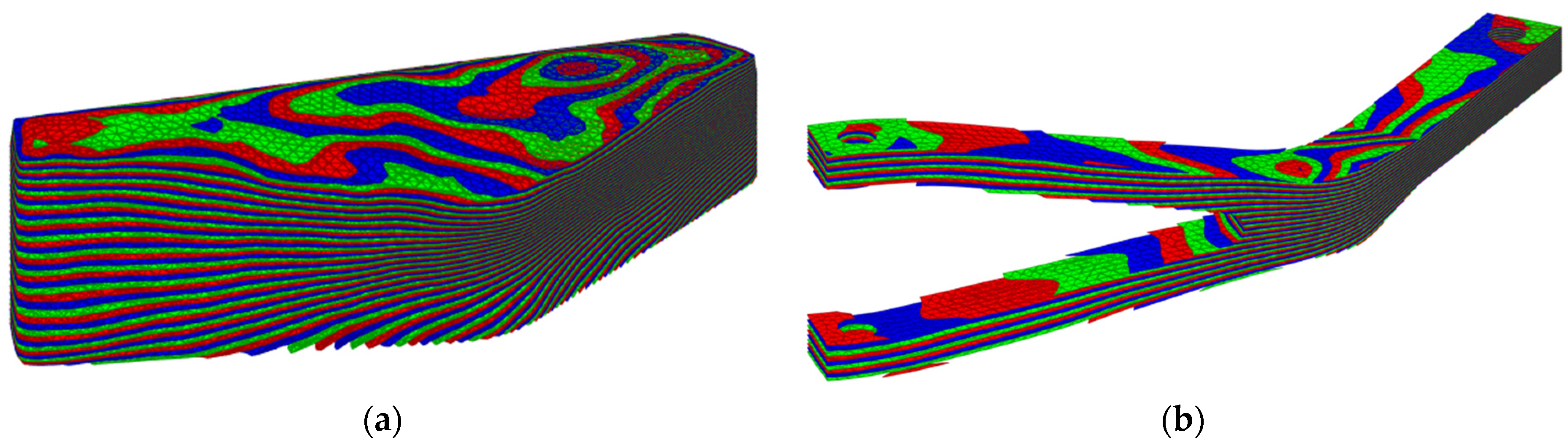
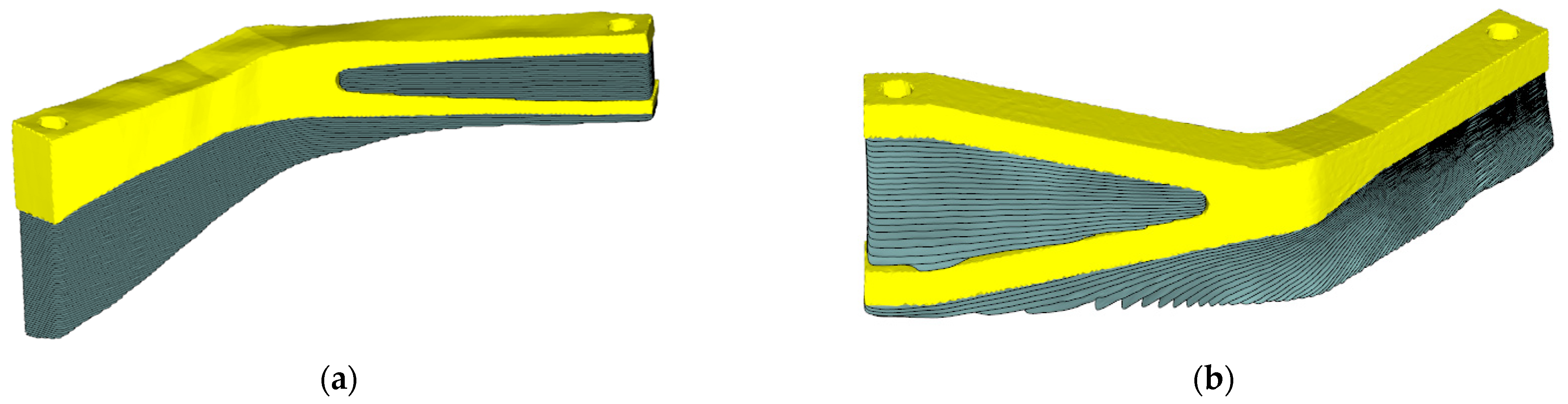
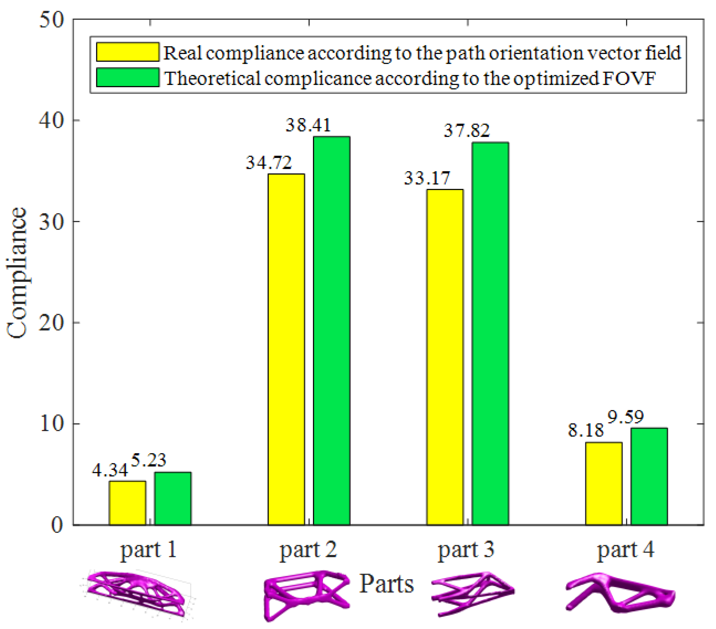
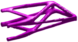
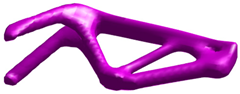
3.2. Multi-Axis Printing of 3D FRC Structures

The traditional three-axis planar slicing process and the multi-axis curved slicing process proposed in this paper are used to print the 3D FRC structure shown in Figure 3. As shown in Figure 23a, the 3D truss structure (160 mm × 40 mm × 40 mm) is sliced into planar layers with a thickness of 0.6 mm. Continuous zigzag paths along the X-axis are planned at each planar layer, as shown in Figure 23b, and the path width is set to 1 mm. Figure 23c shows the printed part with supports, and Figure 23d shows the printed part after removing the supports. Although the truss structure was successfully printed, the printing paths were not aligned with the optimized FOVF; thus, the printed part might not reach the expected mechanical strength.
Figure 24a shows the curved sliced layers of the 3D truss structure and the support structures generated by our method. The curved layer thickness and printing path width are the same as that of three-axis printing. We first generate the printing orientation vector field that is orthogonal to the FOVF. Then, a deformed space is built based on three mutually orthogonal vector fields, where the printed part is sliced into planar layers and the support structures are generated through three-axis printing. Finally, the curved sliced layers in the Euclidean space are obtained by the inverse mapping process. At each sliced curved layer, printing paths are planned according to the projected FOVF, which not only ensures that the paths are aligned with the FOVF but also generates a single-stroke continuous path. Figure 24b shows the printing paths at a curved layer. The final printed part and the part after removing the supports are shown in Figure 24c,d, respectively. The mechanical strengths of the two printed parts were also tested on our press machine, as shown in Figure 25. The structure follows a typical three-point bending topology, with a vertical load applied at the center of the part. It can be observed that the part printed using the proposed method exhibits higher stiffness. Our multi-axis curved layer printing process ensures the printing paths are aligned with the optimized FOVF; thus, the printed part shows superior strength compared to the part printed by the traditional three-axis planar printing process.
Another three FRC structures with FOVFs obtained by topology optimization are shown in Table 2, and they were also successfully printed by using our curved-layer slicing and vector field-driven continuous path planning methods, as shown in Figure 26, Figure 27 and Figure 28; the dimensions of the three parts are 120 mm × 60 mm × 40 mm, 120 mm × 40 mm × 40 mm, and 1220 mm × 40 mm × 40 mm, respectively. The surface quality of the printed parts is not very good due to the low precision of the homemade machine and the effect of the supports, which might be improved by adjusting the printing parameters such as path width and layer thickness. Due to the limited experimental conditions, the parts were printed by a homemade FDM five-axis printer. The surface quality is not very good due to the low precision of the machine and the effect of the supports, not due to the proposed slicing and path planning methods. The mean path orientation errors of the three structures are 4.88°, 5.59°and 4.92°, respectively (see Figure 26b, Figure 27b and Figure 28b). As discussed before, both the curved slicing surfaces and the printing paths cannot be strictly aligned with the defined FOVF unless the FOVF is divergence-free. The deviation between the real path orientation and the theoretic fiber orientation may weaken the mechanical strength of the printed part.
Figure 29 compares the real and theoretical compliance of the four structures; the structural compliance calculated according to the real path orientation vector field is slightly weaker than the theoretical compliance. It is important to note that fiber orientation has a significant impact on the structural strength of the part. Due to the inherent limitations of the method, the printing path orientation cannot be perfectly aligned with the design fiber orientation, which leads to a reduction in structural stiffness. This limitation might be solved by concurrent optimization of the structure and the path process, which will be our future research topic.
Both the proposed curved-layer slicing method and the vector field-driven path planning method primarily rely on solving the Poisson equation, which is a linear system. As a result, the algorithm’s time cost is not a major concern as the computation time is mainly proportional to the mesh size. In the path planning algorithm, an optimization-based approach is used to adjust the intervals between adjacent paths. Gradient-based optimization techniques can be applied to solve this problem, with the computational cost being proportional to the number of printing points. The printed parts show several typical FDM printing defects, including poor layer adhesion, stringing, missing layers, and high porosity. These issues can negatively impact the mechanical properties and overall quality of the printed components. These defects may result from improper printing parameters or the inherent limitations of the FDM process.

4. Conclusions

This paper presents a comprehensive framework for multi-axis printing of fiber-reinforced composite (FRC) structures. Given an FRC part with a defined fiber orientation vector field, the proposed method generates continuous curved-layer printing paths that align with the designed fiber orientations. The approach begins by establishing a printing volume domain that contains the entire printed part. Three mutually orthogonal scalar distance fields within this domain are defined according to the optimized fiber orientation. These fields generate a deformed space, in which planar layers can be mapped to curved layers that are parallel to the fiber orientations in Euclidean space. The continuous printing paths and support structures are planned in this deformed space using a three-axis printing approach. The final multi-axis printing paths are then obtained through an inverse mapping process. To demonstrate the effectiveness of the proposed methods, several structures were successfully printed using the proposed curved-layer slicing and continuous printing path planning techniques. The experimental results validate the superior performance of these methods compared to traditional approaches.
Both the proposed curved-layer slicing method and the vector field-driven path planning method primarily rely on solving the Poisson equation. Due to the nature of the equation, only the least squares solution can be obtained, which means that the planned curved paths cannot strictly align with the defined vector field, unless the vector field is divergence-free. One plausible solution to this problem might be a new structure design method that effectively considers the manufacturing constraints; this will be our future research topic.

Author Contributions

Y.L.: concept, coding, and writing; C.S.: experiment and writing; and X.Y.: editing. All authors have read and agreed to the published version of the manuscript.

Funding

This work was supported by the National Key R&D Program of China (2022YFB4602003), the National Natural Science Foundation of China (Grant Number 52305556), and the Guangdong Basic and Applied Basic Research Foundation (2022A1515110489).

Data Availability Statement

Due to privacy or ethical restrictions, the data is available on request.

Conflicts of Interest

The authors declare that they have no conflicts of interest.

Abbreviations

FRCFiber-reinforced composite
AMAdditive manufacturing
FDMFused deposition modeling

References

  1. Wong, J.; Altassan, A.; Rosen, D.W. Additive manufacturing of fiber-reinforced polymer composites: A technical review and status of design methodologies. Compos. Part B Eng. 2023, 255, 110603. [Google Scholar] [CrossRef]
  2. Li, Y.; Tang, K.; He, D.; Wang, X. Multi-Axis Support-Free Printing of Freeform Parts with Lattice Infill Structures. Comput.-Aided Des. 2021, 133, 102986. [Google Scholar] [CrossRef]
  3. Boon, Y.D.; Joshi, S.C.; Bhudolia, S.K.; Gohel, G. Recent Advances on the Design Automation for Performance-Optimized Fiber Reinforced Polymer Composite Components. J. Compos. Sci. 2020, 4, 61. [Google Scholar] [CrossRef]
  4. Safonov, A.A. 3D topology optimization of continuous fiber-reinforced structures via natural evolution method. Compos. Struct. 2019, 215, 289–297. [Google Scholar] [CrossRef]
  5. Hoglund, R.; Smith, D.E. Continuous fiber angle topology optimization for polymer fused filament fabrication. In Solid Freeform Fabrication Symposium; University of Texas at Austin: Austin, TX, USA, 2016; pp. 1078–1090. [Google Scholar]
  6. Jiang, D.; Hoglund, R.; Smith, D.E. Continuous Fiber Angle Topology Optimization for Poly-mer Composite Deposition Additive Manufacturing Applications. Fibers 2019, 7, 14. [Google Scholar] [CrossRef]
  7. Li, H.; Gao, L.; Li, H.; Li, X.; Tong, H. Full-scale topology optimization for fiber-reinforced structures with continuous fiber paths. Comput. Methods Appl. Mech. Eng. 2021, 377, 113668. [Google Scholar] [CrossRef]
  8. Almeida, J.H.S., Jr.; Christoff, B.G.; Tita, V.; St-Pierre, L. A concurrent fibre orientation and topology optimisation framework for 3D-printed fibre-reinforced composites. Compos. Sci. Technol. 2023, 232, 109872. [Google Scholar] [CrossRef]
  9. Jung, T.; Lee, J.; Nomura, T.; Dede, E.M. Inverse design of three-dimensional fiber reinforced composites with spatially-varying fiber size and orientation using multiscale topology optimization. Compos. Struct. 2022, 279, 114768. [Google Scholar] [CrossRef]
  10. Nomura, T.; Kawamoto, A.; Kondoh, T.; Dede, E.M.; Lee, J.; Song, Y.; Kikuchi, N. Inverse design of structure and fiber orientation by means of topology optimization with tensor field variables. Compos. Part B Eng. 2019, 176, 107187. [Google Scholar] [CrossRef]
  11. Desai, A.; Mogra, M.; Sridhara, S.; Kumar, K.; Sesha, G.; Ananthasuresh, G.K. Topological-derivative-based design of stiff fiber-reinforced structures with optimally oriented continuous fibers. Struct. Multidiscip. Optim. 2021, 63, 703–720. [Google Scholar] [CrossRef]
  12. Huang, Y.; Tian, X.; Wu, L.; Zia, A.A.; Liu, T.; Li, D. Progressive concurrent topological optimization with variable fiber orientation and content for 3D printed continuous fiber reinforced polymer composites. Compos. Part B Eng. 2023, 255, 110602. [Google Scholar] [CrossRef]
  13. Papapetrou, V.S.; Patel, C.; Tamijani, A.Y. Stiffness-based optimization framework for the topology and fiber paths of continuous fiber composites. Compos. Part B Eng. 2020, 183, 107681. [Google Scholar] [CrossRef]
  14. Fernandez, F.; Compel, W.S.; Lewicki, J.P.; Tortorelli, D.A. Optimal design of fiber reinforced composite structures and their direct ink write fabrication. Comput. Methods Appl. Mech. Eng. 2019, 353, 277–307. [Google Scholar] [CrossRef]
  15. Schmidt, M.-P.; Couret, L.; Gout, C.; Pedersen, C.B.W. Structural topology optimization with smoothly varying fiber orientations. Struct. Multidiscip. Optim. 2020, 62, 3105–3126. [Google Scholar] [CrossRef]
  16. Wang, T.; Li, N.; Link, G.; Jelonnek, J.; Fleischer, J.; Dittus, J.; Kupzik, D. Load-dependent path planning method for 3D printing of continuous fiber reinforced plastics. Compos. Part A Appl. Sci. Manuf. 2021, 140, 106181. [Google Scholar] [CrossRef]
  17. Li, N.; Link, G.; Wang, T.; Ramopoulos, V.; Neumaier, D.; Hofele, J.; Walter, M.; Jelonnek, J. Path-designed 3D printing for topological optimized continuous carbon fibre reinforced composite structures. Compos. Part B Eng. 2020, 182, 107612. [Google Scholar] [CrossRef]
  18. Chen, X.; Fang, G.; Liao, W.-H.; Wang, C.C.L. Field-Based Toolpath Generation for 3D Printing Continuous Fibre Reinforced Thermoplastic Composites. Addit. Manuf. 2022, 49, 102470. [Google Scholar] [CrossRef]
  19. Breseghello, L.; Naboni, R. Toolpath-based design for 3D concrete printing of carbon-efficient architectural structures. Addit. Manuf. 2022, 56, 102872. [Google Scholar] [CrossRef]
  20. Fang, G.; Zhang, T.; Zhong, S.; Chen, X.; Zhong, Z.; Wang, C.C.L. Reinforced FDM: Multi-axis filament alignment with controlled anisotropic strength. ACM Trans. Graph. 2020, 39, 1–15. [Google Scholar] [CrossRef]
  21. Xia, L.; Lin, S.; Ma, G. Stress-based tool-path planning methodology for fused filament fabrication. Addit. Manuf. 2020, 32, 101020. [Google Scholar] [CrossRef]
  22. Ichihara, N.; Ueda, M. 3D-printed high-toughness composite structures by anisotropic topology optimization. Compos. Part B Eng. 2023, 253, 110572. [Google Scholar] [CrossRef]
  23. Qiu, Z.; Li, Q.; Luo, Y.; Liu, S. Concurrent topology and fiber orientation optimization method for fiber-reinforced composites based on composite additive manufacturing. Comput. Methods Appl. Mech. Eng. 2022, 395, 114962. [Google Scholar] [CrossRef]
  24. Fang, G.; Zhang, T.; Huang, Y.; Zhang, Z.; Masania, K.; Wang, C.C. Exceptional mechanical performance by spatial printing with continuous fiber: Curved slicing, toolpath generation and physical verification. Addit. Manuf. 2024, 82, 104048. [Google Scholar] [CrossRef]
  25. Zhang, T.; Fang, G.; Huang, Y.; Dutta, N.; Lefebvre, S.; Kilic, Z.M.; Wang, C.C.L. S3-Slicer: A General Slicing Framework for Multi-Axis 3D Printing. ACM Trans. Graph. 2022, 41, 1–15. [Google Scholar] [CrossRef]
  26. Liu, T.; Zhang, T.; Chen, Y.; Huang, Y.; Wang, C.C.L. Neural Slicer for Multi-Axis 3D Printing. ACM Trans. Graph. 2024, 43, 1–15. [Google Scholar] [CrossRef]
  27. Bi, M.; Xia, L.; Tran, P.; Li, Z.; Wan, Q.; Wang, L.; Shen, W.; Ma, G.; Xie, Y.M. Continuous contour-zigzag hybrid toolpath for large format additive manufacturing. Addit. Manuf. 2022, 55, 102822. [Google Scholar] [CrossRef]
  28. Zhao, H.; Gu, F.; Huang, Q.-X.; Garcia, J.; Chen, Y.; Tu, C.; Benes, B.; Zhang, H.; Cohen-Or, D.; Chen, B. Connected fermat spirals for layered fabrication. ACM Trans. Graph. 2016, 35, 1–10. [Google Scholar] [CrossRef]
  29. Zhai, X.; Chen, F. Path Planning of a Type of Porous Structures for Additive Manufacturing. Comput.-Aided Des. 2019, 115, 218–230. [Google Scholar] [CrossRef]
  30. Li, Y.; Yuan, S.; Zhang, W.; Zhu, J. A new continuous printing path planning method for gradient honeycomb infill structures. Int. J. Adv. Manuf. Technol. 2023, 126, 719–734. [Google Scholar] [CrossRef]
  31. Gomez, G.; Cortés, C.; Creus, C.; Amilibia, M.Z.; Moreno, A. Generation of continuous hybrid zig-zag and contour paths for 3D printing. Int. J. Adv. Manuf. Technol. 2022, 119, 7025–7040. [Google Scholar] [CrossRef]
  32. Huang, Y.; Tian, X.; Zheng, Z.; Li, D.; Malakhov, A.V.; Polilov, A.N. Multiscale concurrent design and 3D printing of continuous fiber reinforced thermoplastic composites with optimized fiber trajectory and topological structure. Compos. Struct. 2022, 285, 115241. [Google Scholar] [CrossRef]
  33. Li, Y.; He, D.; Yuan, S.; Tang, K.; Zhu, J. Vector field-based curved layer slicing and path planning for multi-axis printing. Robot. Comput. -Integr. Manuf. 2022, 77, 102362. [Google Scholar] [CrossRef]
  34. Edelsbrunner, H.; Mücke, E.P. Three-dimensional alpha shapes. ACM Trans. Graph. 1994, 13, 43–72. [Google Scholar] [CrossRef]
  35. Zhou, W.; Yan, H. Alpha shape and Delaunay triangulation in studies of protein-related interactions. Brief. Bioinform. 2014, 15, 54–64. [Google Scholar] [CrossRef]
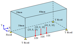
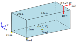
Figure 1. Multi-axis printing process planning for FRC structures: (a) designing a fiber orientation vector field; (b) defining a printing volume domain; (c) generating the nozzle orientation vector field; and (d) curved-layer slicing and path planning.
Processes 13 00473 g001
Figure 2. Generate a fiber orientation vector field by control points.
Processes 13 00473 g002
Figure 3. Topology optimization of an FRC structure: (a) design domain and boundary condition; (b) the elastic matrix of the anisotropic material; (c) optimized topology optimization; and (d) optimized fiber orientations.
Processes 13 00473 g003
Figure 4. Generation of the nozzle orientation vector field: (a) FOVF F v and (b) NOVF P v .
Processes 13 00473 g004
Figure 5. Curved-layer slicing: (a) printing volume domain and (b) printed part.
Processes 13 00473 g005
Figure 6. Iteration curve (a) and histogram of the orientation error (b).
Processes 13 00473 g006
Figure 7. Mapping between the Euclidean space (X, Y, and Z) and deformed space ( ϕ w , ϕ u , and ϕ p ).
Processes 13 00473 g007
Figure 8. Illustration of the adaptive slicing algorithm.
Processes 13 00473 g008
Figure 9. Mapping from the curved surface to the 2D planar surface.
Processes 13 00473 g009
Figure 10. Continuous printing path planning: (a) iso-lines of the scalar field and the offset boundary curves; (b) iso-lines trimmed by the offset boundary curves; (c) trimmed sub-loops; and (d) connected Eulerian path.
Processes 13 00473 g010
Figure 11. Optimization of the path interval.
Processes 13 00473 g011
Figure 12. Support regions of the part in the deformed space χ .
Processes 13 00473 g012
Figure 13. Generation of the support surface: (a) projected vertices and part surface; (b) offset boundary of the part surface; (c) use the alpha-shape algorithm to generate support surface; and (d) plan the printing path on the support surface and the part surface.
Processes 13 00473 g013
Figure 14. Support structure of the printed part: (a) in the deformed space χ and (b) the Euclidean space.
Processes 13 00473 g014
Figure 15. Homemade five-axis double-nozzle 3D printer.
Processes 13 00473 g015
Figure 16. Curved surface and vector field: (a) triangular mesh of the curved surface and (b) fiber orientation vector field obtained by interpolation.
Processes 13 00473 g016
Figure 17. Continuous printing path based on the planned vector field: (a) the continuous path without optimizing the path interval and (b) the continuous path after optimizing the path interval.
Processes 13 00473 g017
Figure 18. Iteration curve of the path interval optimization.
Processes 13 00473 g018
Figure 19. Path orientation error: (a) path orientation error at different places and (b) histogram of the path orientation error.
Processes 13 00473 g019
Figure 20. Physical printing of the vector field-driven continuous path on the curved surface: (a) printing process and (b) final printed curved surface.
Processes 13 00473 g020
Figure 21. Printing of the 2D topology structure: (a) topology structure and FOVF; (b) curved path; (c) horizontal zigzag path; and (d) vertical zigzag path.
Processes 13 00473 g021
Figure 22. Experimental load–deflection curves of the 2D topology structures: (a) load–deflection curves and (b) experimental setup.
Processes 13 00473 g022
Figure 23. Planar-layer printing of the topology structure: (a) planar-layer slicing; (b) zigzag printing path at a layer; (c) printed part; and (d) printed part after removing the supports.
Processes 13 00473 g023
Figure 24. Curved-layer printing of the topology structure: (a) curved-layer slicing; (b) curved printing path at a layer; (c) printed part with supports; and (d) printed part after removing the supports.
Processes 13 00473 g024aProcesses 13 00473 g024b
Figure 25. Experimental load–deflection curves of the 3D topology structures: (a) load–deflection curves and (b) experimental setup.
Processes 13 00473 g025
Figure 26. Multi-axis printing of truss structure 1: (a) curved-layer slicing; (b) histogram of path orientation error; (c) printed part; and (d) printed part after removing the supports.
Processes 13 00473 g026aProcesses 13 00473 g026b
Figure 27. Multi-axis printing of truss structure 2: (a) curved-layer slicing; (b) histogram of path orientation error; (c) printed part; and (d) printed part after removing the supports.
Processes 13 00473 g027
Figure 28. Multi-axis printing of truss structure 3: (a) curved-layer slicing; (b) histogram of path orientation error; (c) printed part; and (d) printed part after removing the supports.
Processes 13 00473 g028aProcesses 13 00473 g028b
Figure 29. Comparison of the real and theoretical compliance of the four structures.
Processes 13 00473 g029
Table 1. Parameters of FDM Printing.
ParametersValue
MaterialPLA
Layer thickness0.6 mm
Path width0.8 mm
Printing temperature180 °C
Table 2. FRC structures with FOVF obtained by topology optimization.
Boundary ConditionTopology ShapeFiber Orientation Vector Field
Processes 13 00473 i001Processes 13 00473 i002Processes 13 00473 i003
Processes 13 00473 i004Processes 13 00473 i005Processes 13 00473 i006
Processes 13 00473 i007Processes 13 00473 i008Processes 13 00473 i009
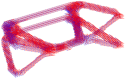
Disclaimer/Publisher’s Note: The statements, opinions and data contained in all publications are solely those of the individual author(s) and contributor(s) and not of MDPI and/or the editor(s). MDPI and/or the editor(s) disclaim responsibility for any injury to people or property resulting from any ideas, methods, instructions or products referred to in the content.

