1. Introduction
Axial piston pumps are widely used in mechanical equipment due to their advantages such as low noise and accurate performance. These pumps enable oil discharge and suction processes through the telescopic movement of the piston [
1,
2]. The force condition of the piston-returning spherical joint pair in the pump is different from that of other friction pairs. When the piston–slipper kit is located in the oil discharge area, the spherical joint pair is impacted and squeezed by the high-pressure oil. And when the piston–slipper kit enters the oil suction area from the oil discharge area, the spherical joint pair is subjected to a returning force from the returning mechanism and a tensile force from the negative pressure in the piston cavity; this gives the piston and slipper a tendency to separate, which can lead to slippers loosening and detaching [
3,
4].
The piston-returning spherical joint pair continuously bears alternating loads generated by the high-to-low-pressure conversion. When the pump operates at high speed, the piston changes direction more frequently. And when the spherical joint pair reaches the fatigue limit, failure phenomena such as slippers falling off, cracking, and even piston ball head breaking can occur, affecting the service life of the pump [
5,
6]. Therefore, it is vital to understand the strength properties of the piston-returning spherical joint pair in an axial piston pump.
To date, the following results have been achieved in research on the strength of spherical joint pairs in axial piston pumps. Muthuvignesh K and others studied the elastic deformation of the ball head and spherical socket of a piston-returning spherical joint pair, performed steady-state characteristic analysis and structural optimization on the joint pair and studying the influence of structural changes on the stress distribution [
7]. Duan Shanshan analyzed the influence of working condition parameters on the force and moment of the joint pair and the stress distribution of the piston and slipper. It was found that under high-speed and high-load working conditions, the piston is prone to slipper detachment and neck fracturing [
8]. Investigating the loosening failure problem in spherical hinge pairs in seawater piston pumps, Hu Zhiwei proposed methods such as increasing the axial dimension of the spherical socket of the joint pair, improving the strength of the center position and selecting a more wear-resistant, high-stiffness material for the slipper socket that could withstand high-speed impacts [
9]. Li DL et al. characterized the stress and strain, the load borne, the failure behavior, and the macroscopic and microscopic morphology during the closing process of a piston-returning spherical joint pair. It was found that the residual stress generated during the crimping and closing of the pair was the main reason for its loosening failure, and wear may be a secondary factor [
10]. Also, Shen H et al. used the virtual prototype method to carry out kinematic and dynamic simulations of the piston-returning spherical joint pair of an axial piston pump, established a ball plug contact model, and analyzed the influence of the oil pressure, piston radius, and radial clearance on the normal displacement, contact radius, maximum contact pressure, and contact stiffness [
11].
In addition, some scholars have studied the strength of spherical joint pairs from the perspective of processing technology. By addressing existing problems in spherical hinge pairs, Wei Fen et al. effectively solved the anti-fatigue cracking problem related to spherical socket closure by optimizing the transition fillet and reducing the difference in wall thickness. They also achieved process optimization by controlling factors such as the roughness of the inner cavity of the spherical socket closure, the ball diameter of the slipper spherical socket, and the tolerance of the piston ball head [
12]. Mao Yilong analyzed the influence of different process parameters on the spinning force and work-piece quality, determined the shape and size of the frame of the slipper shutting machine, and carried out load analysis on the frame, specifically investigating its strength and stiffness [
13]. Additionally, Liu Huixiang studied the shutting capabilities of a piston-returning spherical joint pair for aerospace applications. It was found that the shutting number and the deformation amount corresponding to a single shutting of the spherical joint pair directly determined the quality of the slipper shutting, and the optimal shutting number was determined through simulation analysis [
14]. In a similar vein, Zhu Chunjiang et al. proposed a shutting method for slippers suitable for aviation piston pumps. This method caused the spherical socket hole of the slipper to deform along the spherical surface of the piston through the combined action of a press, tooling, and wrapping around the spherical surface of the piston ball head. Subsequently, it was rolled into the spherical socket closure with a milling machine [
15]. Li Liang obtained the stress and deformation distributions of a piston–slipper kit through the simulation and testing of the spherical joint pair slippage. By comparing the load–deformation curves of the test and simulation, it was revealed that there was little difference between the slippage test and the simulation result [
16]. It was hypothesized that during the working process of the slipper, the maximum stress and strain occurred at the slipper spherical socket pad, which increased the deformation of the slipper. Yao Y et al. proposed a finite element method for analyzing stress, strain, and forces in the rolling process [
17]. It was demonstrated that the method could optimize the design of a piston, slipper, and mold. Cao Gairong et al. took the swash plate axial piston pump as an example. They introduced the common forms, damage types, and fault phenomena of piston slipper assemblies. Then, they analyzed the causes in relation to aspects such as hydraulic system design, end user working conditions, and the design, technology, and machining of the piston pump itself. Corresponding improvement methods for different causes of damage were put forward, which have certain reference effects on the design of piston slipper assemblies in swash plate axial piston pumps and maintenance and performance improvement in piston pumps [
18]. Li Hao et al. established a finite element model based on a certain plunger assembly model. They conducted a simulation analysis of the spinning and closing process of this plunger assembly and calculated the spinning force, pull-off force, and axial clearance during the spinning process. The simulation results showed that during the spinning forming process, the stress is relatively concentrated in the contact area between the slipper and the roller, and the circumferential stress distribution of the slipper is relatively uniform. In addition, when the plunger comes into contact with the upper half of the inner spherical surface of the slipper, the spinning force begins to be generated, and it shows a changing trend, first increasing and then decreasing. The pull-off force also shows the trend of first increasing and then slowly decreasing over time. At the same time, it was clarified that the axial clearance could be obtained by analyzing the axial pressure between the contact surfaces of the plunger and the slipper [
19].
From a review of the above studies, it is clear that the current research on piston-returning spherical joint pairs mainly focuses on axial piston pumps used in general engineering. The studies mainly emphasize the structural optimization design of the spherical joint pair and improving the shutting process of joint pairs. However, there are few studies on spherical joint pairs used in high-speed axial piston pumps and on the factors affecting the strength of the joint pairs in such pumps. Given the scarcity of research in this specific area, this study aimed to bridge the existing knowledge gap by combining strength simulations and experimental analyses. By doing so, we aimed to identify the key factors that influence the strength of these joint pairs under high-speed operating conditions.
Through the implementation of strength simulations and well-designed experiments, this study aimed to generate detailed data on the failure modes, stress distributions, and deformation characteristics of piston-returning spherical joint pairs in high-speed axial piston pumps. The outcomes will include a comprehensive understanding of the relationship between various factors, such as operating speed, pressure, and material properties, and the strength of the joint pairs. This knowledge will provide a solid foundation for the development of more robust and reliable joint pair designs.
2. Force Analysis of the Piston and Slipper
To study the strength of the piston-returning spherical joint pair and design subsequent experiments, we first performed a force analysis on the piston–slipper kit. Compared with the oil suction area, the force condition of the joint pair in the oil discharge area is more complex. Therefore, the force of the piston–slipper kit during the oil discharge process is analyzed here [
20].
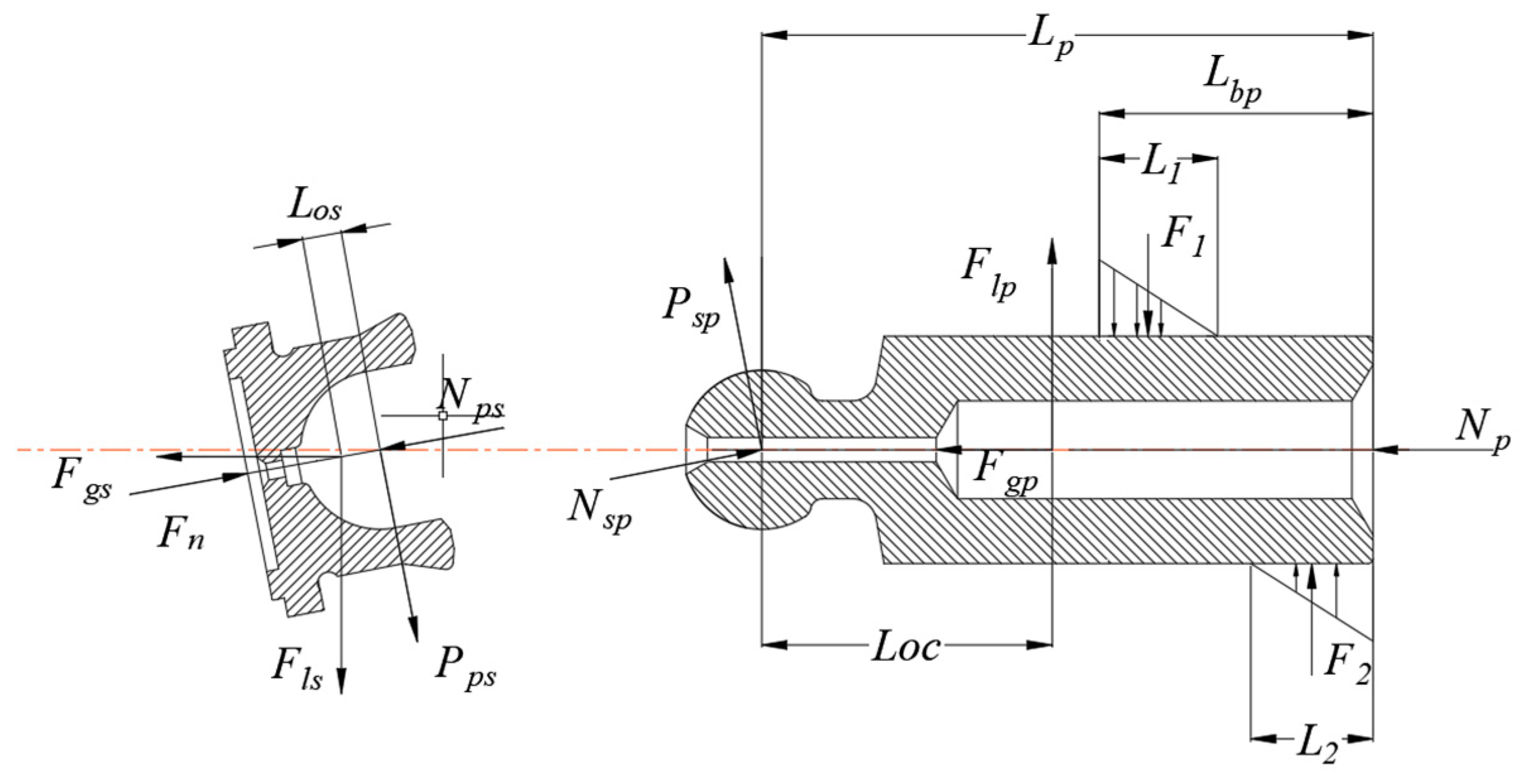
The forces on the piston and slipper of the axial piston pump are shown in
Figure 1. The forces on the piston mainly include the hydraulic pressure
Np from the bottom of the piston, the radial inertial force
Flp and axial inertial force
Fgp that the piston is subjected to during the rotation of the cylinder block, the normal forces
N1 and
N2 between the piston and the piston hole, the frictional forces
F1 and
F2 between the piston and the piston hole, and the forces
Psp and
Nsp of the slipper on the piston. The slipper mainly bears the forces
Pps and
Nps from the piston ball head, the supporting reaction force
Fn of the swashplate, and the radial inertial force
Fls and axial inertial force
Fgs of the slipper.
The five general categories of forces acting on the piston are as follows [
21]:
- (1)
The pressure
of the hydraulic oil acting on the bottom of the piston:
where
is the oil pressure in the piston chamber (in Pa), and
is the diameter of the piston (in m).
- (2)
The radial inertia force
and axial inertia force
acting on the piston:
where
is the mass of the piston (kg);
is the radius of the distribution circle where the piston is located (m);
is the angular velocity of the rotor (rad/s);
is the inclination angle of the swashplate (degrees); and
is the angle between the piston at any position and the starting position of the oil discharge (degrees).
- (3)
The normal force
N1 and
N2 between the piston and the piston hole:
where
and
are the contact lengths between the piston and the piston holes on both sides, respectively (m).
- (4)
The friction forces
F1 and
F2 between the piston and the piston hole.
where
is the coefficient of friction between the piston and the piston hole.
The formula for the force acting on the slipper is as follows:
The radial inertial force
and axial inertial force
of the slipper:
where
is the mass of the slipper (kg), and
is the distance from the center of the spherical socket of the slipper to the center of mass of the slipper (m).
We can assemble the slipper in
Figure 1 with the piston to form a piston-returning spherical joint pair. The equations for the piston–slipper assembly are as follows:
where
is the distance from the center of the piston ball head to the bottom of the piston (m);
is the distance from the starting position of the upper force triangle of the piston to the bottom of the piston (m); and
is the distance from the center of the piston ball head to the center of mass of the piston (m).
The force
can be obtained from Equations (1)–(9) as follows:
where
,
.
The slipper was selected as our research object, and the force–balance equation is as follows:
The force
can be obtained from Equation (11) as follows:
When the force
Fn from Equation (10) is substituted into (12), the force
can be obtained as follows:
And the force
can be obtained from Equation (11) as follows:
When the forces
and
(from Equations (7) and (8)) are substituted into Equation (14), the force
can be obtained:
It can be seen that the forces and of the piston-returning spherical joint pairs are related to factors such as the rotational speed of the pump, the inclination angle of the swashplate, the structural parameters of the piston, and the mass of the piston and the slipper. When the mass and structural parameters are fixed, they are mainly affected by the rotational speed and working pressure of the pump.
3. Pushing and Pulling Strength Tests on Piston–Slipper Kit
3.1. Test Principle
During the working process of the axial piston pump, the piston-returning spherical joint pair continuously bears alternating loads from high-to-low-pressure conversion. In order to determine the strength change in the joint pair and its influencing factors, we designed a test device to carry out experiments. The rated working pressure of the pump used for this project is 21 MPa, and the rated speed is 11,000 r/min. The laboratory could not perform the strength test of the joint pair under the rated parameters of the real pump, so a pushing and pulling test-bed for the spherical joint pair was built to carry out research.
First, a hydraulic system was designed, and a hydraulic pump was used to output a certain pressure of oil, which could push the hydraulic cylinder. One end of the piston-returning spherical joint pair is fixed, and the other end is connected with the piston rod of the hydraulic cylinder. The force output from the extension and retraction of the hydraulic cylinder simulates the cycle change load received by the joint pair during the operation of the piston pump. The pressure sensor is used to record the pressure of the two chambers of the hydraulic cylinder, and the pressure relay and programmable controller are used in tandem to control the action of the electromagnetic reversing valve, enabling the telescopic movement of the hydraulic cylinder and the application of pushing and pulling forces. The reversing frequency of the hydraulic cylinder can be adjusted by changing the size of the throttle valve.
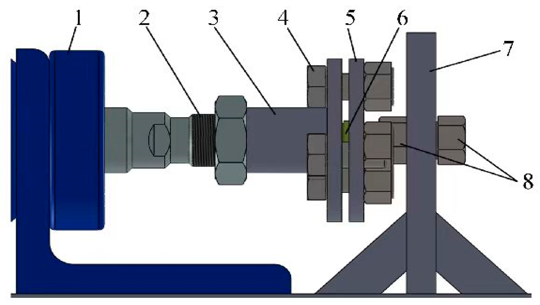
In order to fix the piston-returning spherical joint pair, the installation device was designed, as shown in
Figure 2. The threads are machined on the surface of the piston, and the piston is installed on a fixed steel plate through the threads. The slipper is fixed in the middle of two disks, and the disks are installed on the hydraulic cylinder piston rod through the threaded disk and the screw rod. The pushing and pulling process of the piston–slipper kit is simulated through the expansion and contraction of the hydraulic cylinder piston rod. The setup of the entire test-bed is shown in
Figure 3.
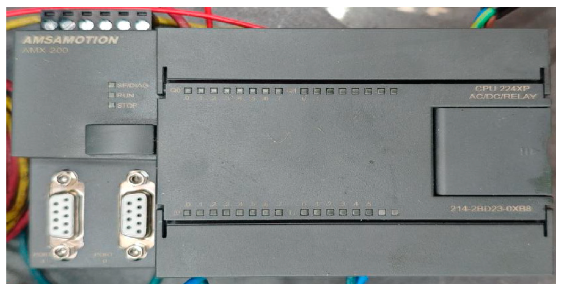
The test control mainly involves using a programmable logic controller (PLC) to control the commutation of a three-position four-way solenoid directional valve. The PLC used is the Aimoxun CPU224XP, which is compatible with the Siemens S7-200. It has advantages such as a compact structure, a relatively fast real-time response, and the ability to provide rapid and precise control of sequences and process control, as shown in
Figure 4. Connect the PLC and the computer terminal through a USB-PPI cable. Then, use the STEP7-Micro/WIN V4.0 SP9 programming software to set the communication parameters to complete the communication between the PLC and the computer. Design and program the required procedures using the PLC programming software. After the programming is completed, download the program block to the PLC. The PLC controls the commutation of the three-position four-way solenoid directional valve through this program.
The data monitoring mainly relies on the pressure sensors in the pipelines to achieve the function of real-time pressure monitoring in the hydraulic cylinder. Connect the signal line of the pressure sensor to the signal input terminal of the oscilloscope. After the electronic signal output by the pressure sensor enters the signal input terminal of the oscilloscope, the pressure change trends and patterns in the hydraulic cylinder can be detected in real time using an oscilloscope, as shown in
Figure 5. The data stored in the oscilloscope can be transferred to the computer via a USB flash drive. In
Figure 5, the display screen of the oscilloscope shows Chinese. The right column of the display screen is the storage column. From top to bottom, they are storage type, reference waveform, signal source, save, and export options. The lower side of the display screen shows the graphic numerical display. From left to right, they are maximum value, minimum value, frequency, and average value.
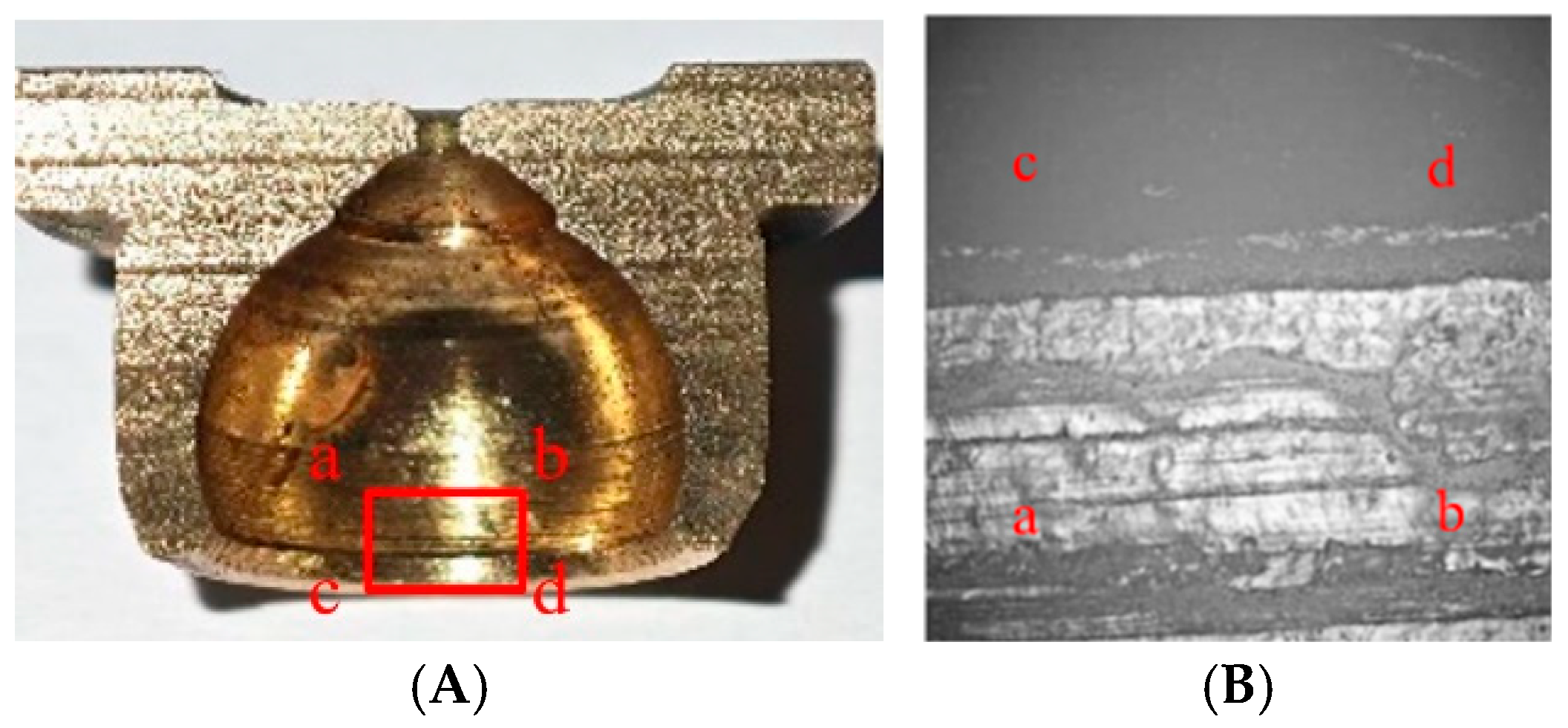
The change in the axial clearance can be obtained by measuring the total length of the piston–slipper kit with a micrometer, before and after the test. In this study, we mainly analyzed the wear deformation at the spherical socket closure of the slipper. After the test, the slipper was wire-cut. The slipper section is shown in
Figure 6A. White light interference topography is used to observe the spherical socket closure of the slipper (the
abcd frame selection position shown in
Figure 6), with its surface topography shown in
Figure 6B. After the test, it was found that there were obvious wear marks at the contact position between the piston ball head and the spherical socket closure of the slipper. The wear marks had a ring shape, mainly appearing at the connection between the piston ball head and the spherical socket closure.
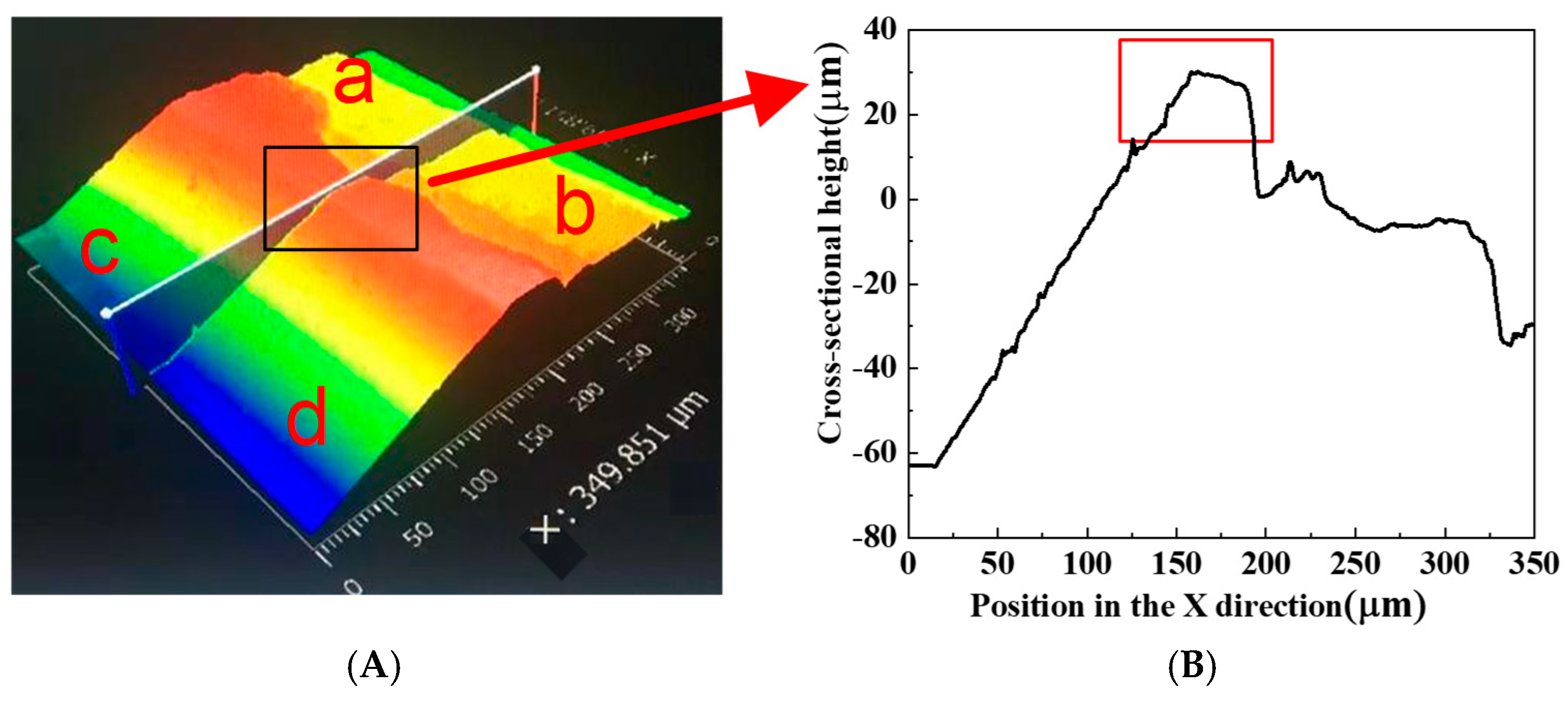
The three-dimensional topographic cloud map of the inner surface of the spherical socket closure, obtained by scanning with white light interference topography, is shown in
Figure 7A. The peak in the middle of ab and cd acts as a card for the piston ball head in the spherical socket. In order to more accurately observe the radial deformation of the spherical socket closure, a section is selected from the middle position of the cloud map (the midpoint line between
ab and
cd in the figure), and the cross-sectional shape curve is drawn, as shown in
Figure 7B. The graph is drawn along the x-axis direction with the midpoint of cd as the origin, and the starting point of the x-axis is the position of the spherical socket closure of the slipper. For ease of comparison, the spherical socket closures of the slippers that have not been tested are also cut and scanned.
From the three-dimensional topography of the slipper interface and the cross-sectional curve of the spherical socket closure, it can be seen that the x-direction range of the spherical socket closure is 150~190 μm (the box position in the three-dimensional topography cloud map is selected). From the inside and outside of the spherical socket closure, the curve shape is relatively convex, which can contribute to the ball head becoming stuck. Therefore, the shape curve of the spherical socket closure position is selected for comparative analysis. After 190 μm, the range is inside the spherical socket closure, and a small part of the depression position has furrow wear marks generated by machining.
3.2. Influence of Pushing and Pulling Forces on the Deformation of the Spherical Socket Closure of the Slipper
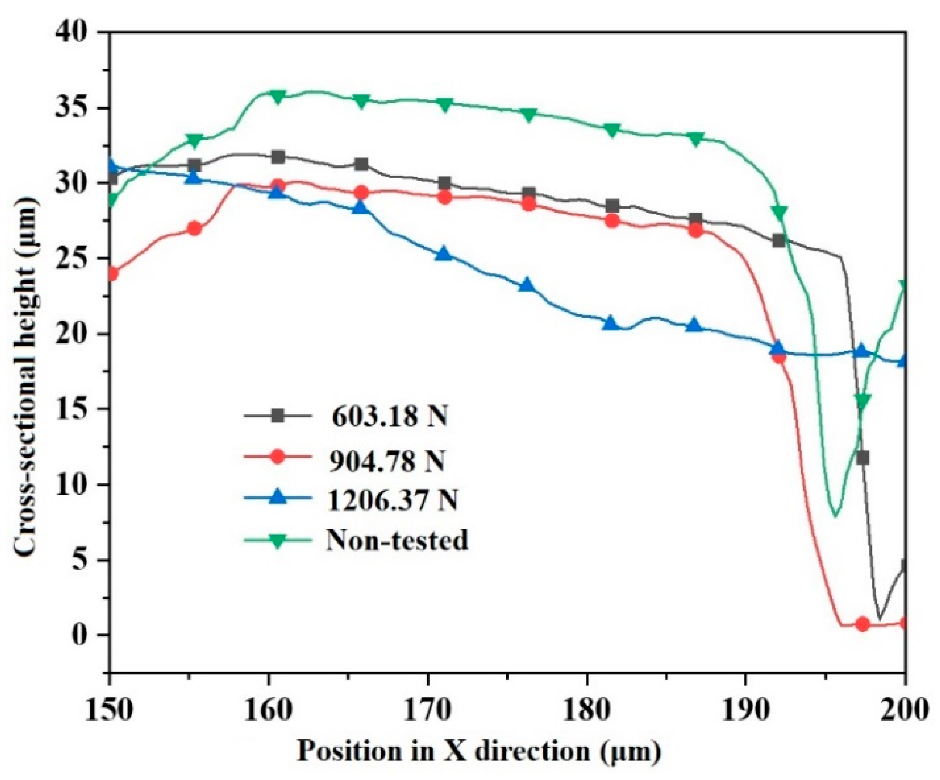
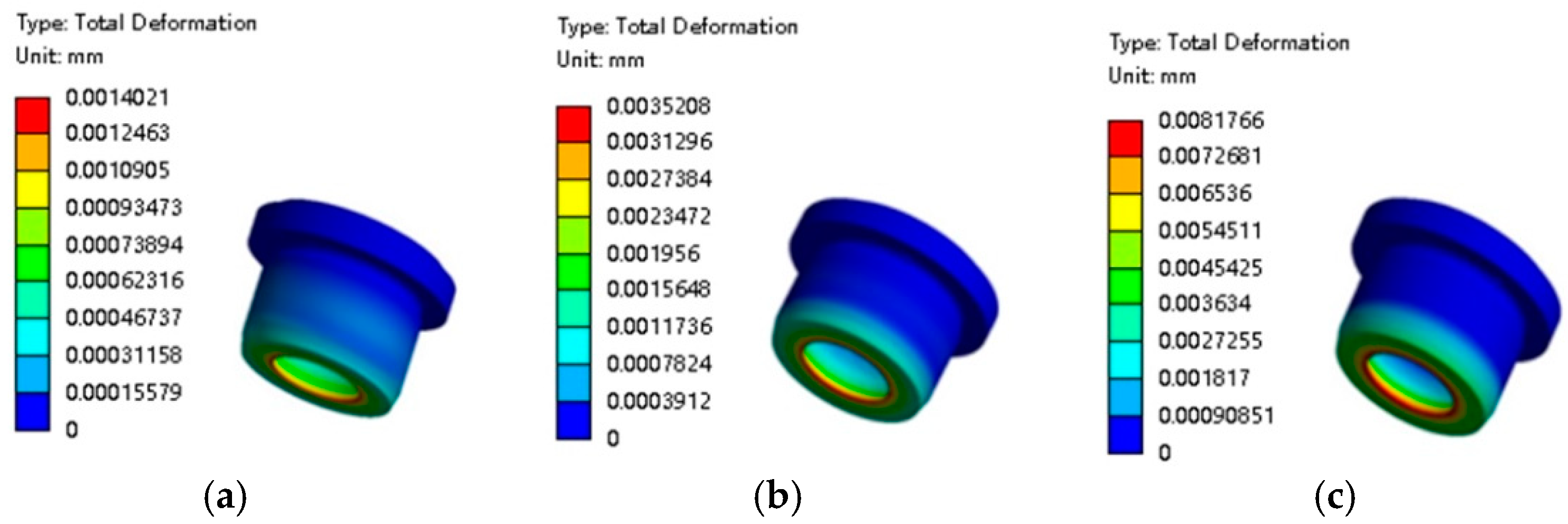
The pushing and pulling forces of the output piston rod of the hydraulic cylinder are applied to the piston-returning spherical joint pair, and the influence of these forces on the deformation of the spherical socket closure is studied through changes in the cross-sectional curve. The rated pressure of the studied axial piston pump is 21 MPa, and the speed is 11,000 r/min. For optimal laboratory conditions and safety, the pressure relay of the rodless chamber oil circuit of the hydraulic cylinder is set to 2 MPa, and the pushing force of the hydraulic cylinder is set to 1067.68 N, informed by calculations. The pressure relay of the hydraulic cylinder with the rod cavity oil circuit is set to 1 MPa, 1.5 MPa, and 2 MPa for three working conditions, respectively. The pulling forces of the hydraulic cylinder piston rod corresponding to the three pressures are 603.18 N, 904.78 N, and 1206.37 N, respectively. The frequency of the hydraulic cylinder piston rod is set at 600 times per minute, and the hydraulic cylinder piston rod is pushed and pulled over 6000 cycles.
Throughout the test, the change curve of the shape of the spherical socket closure section of the slipper is obtained for different pulling forces, as shown in
Figure 8.
When the pulling force of the piston rod of the hydraulic cylinder is 603.18 N, the maximum deformation of the spherical socket closure is 5.52 μm compared to the untested slipper. When the pulling force of the piston rod is 904.78 N, the maximum deformation is 6.30 μm, and the shape curve of the spherical socket closure is similar to the shape curve of the spherical socket closure when the pulling force of the piston rod is 603.18 N; moreover, the height difference between the two is small. When the pulling force of the piston rod is 1206.37 N, the maximum deformation is 13.06 μm. Compared with the shape curve of the non-tested spherical socket closure section, the height difference in the raised part is larger. This is due to the increase in the pulling force of the piston rod, meaning that the wear amount at the spherical socket closure becomes larger. Moreover, the cross-sectional curve of the spherical socket closure is in the shape of the outer height and the inner low, and the slope is large, indicating that when the pulling force is 1206.37 N, the deformation amount near the raised position of the spherical socket closure increases.
From the tests, it is clear that with the increase in piston rod pulling force, the deformation of the spherical socket closure also increases. This indicates that the wear at the spherical socket closure also increases with the increase in pulling force, and the deformation is not proportional to the pushing and pulling force.
3.3. Influence of Pushing and Pulling Cycles on the Deformation of the Spherical Socket Closure of the Slipper
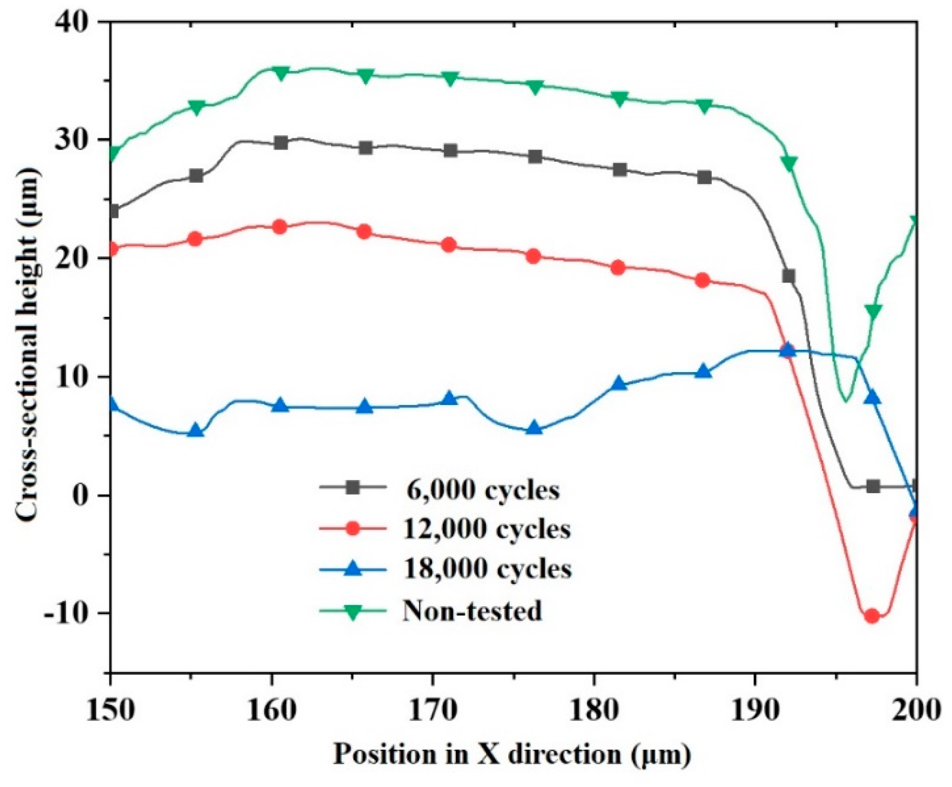
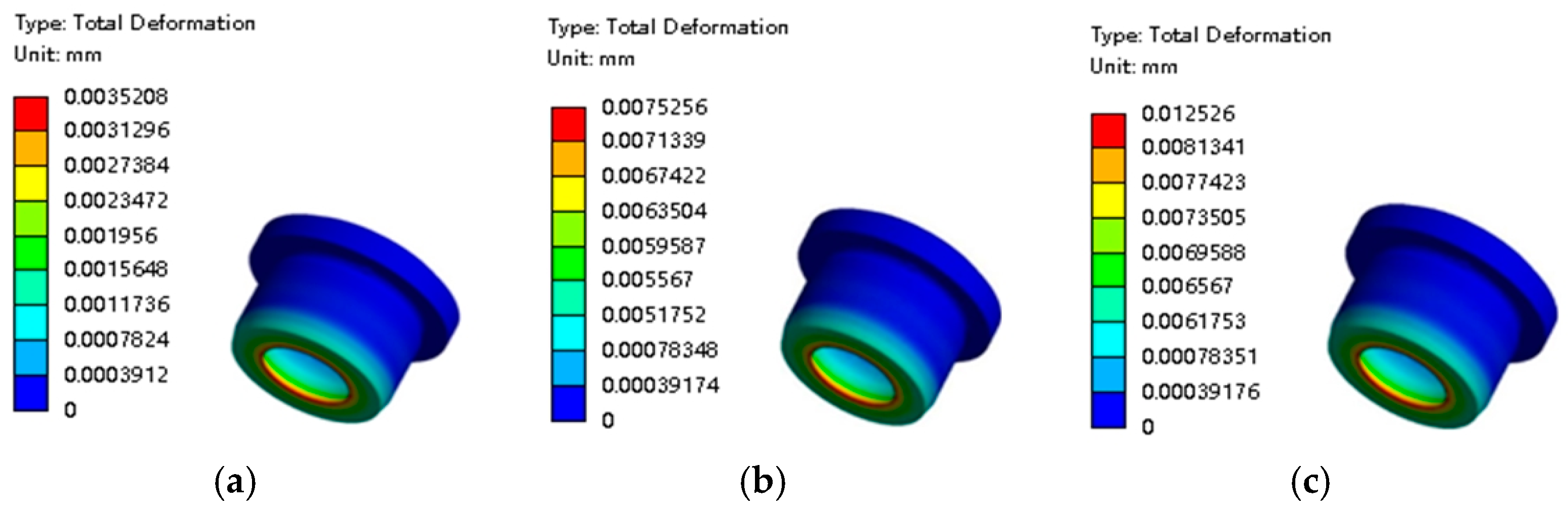
The pressure relay on the side of the rod cavity of the hydraulic cylinder was adjusted to 1.5 MPa; that is, the pulling force of the piston rod of the hydraulic cylinder was 904.78 N. In order to test the influence of the number of pushing and pulling cycles on the deformation of the spherical socket closure of the slipper, the number of cycles was set to 6000, 12,000, and 18,000 times. The cross-sectional shape curves of the spherical socket closure at three different pushing and pulling times were obtained, as shown in
Figure 9.
It can be seen from
Figure 9 that compared with the non-tested slippers, the maximum deformation of the spherical socket closures of the slippers after 6000 pushing and pulling tests is 6.24 μm, and the raised height at the spherical socket closure shows a certain decrease. The raised height decreases relatively smoothly in the range of 150~180 μm. The section maximum deformation of the spherical socket closure of the slipper after 12,000 pushing and pulling tests is 14.83 μm, and the section maximum deformation after 18,000 pushing and pulling tests is 29.20 μm. At this time, the section deformation of the spherical socket closure is relatively large, which is due to the large number of pushing and pulling cycles, in turn increasing the wear of the spherical socket closure of the slipper. Moreover, the cross-sectional shape curve of the closure shows the shape of an inner high and an outer low. In the range of 170~180 μm, the shape curve appears concave, indicating that there is major deformation and serious wear occurring in that area.
3.4. Influence of Material Type on the Deformation of the Spherical Socket Closure of the Slipper
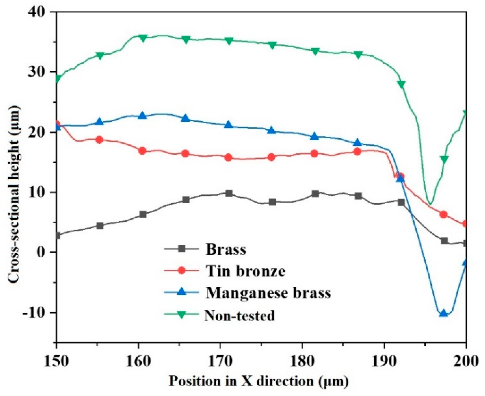
In order to determine the influence of slipper materials on the deformation of the spherical socket closure of the slipper, three materials—manganese brass, tin bronze, and ordinary brass—were selected to construct the tested slipper.
The oil pressure of the rod cavity was set to 1.5 MPa, and the oil pressure of the rodless cavity was set to 2 MPa; that is, the pushing and pulling forces of the spherical joint pair were 904.78 N and 1206.37 N, respectively. The pushing and pulling frequency of the spherical joint pair was adjusted by the throttle valve to 600 cycles per minute, and the pushing and pulling time was 20 min; that is, the test consisted of 12,000 cycles.
The cross-sectional shape curves of the spherical socket closures using the three different materials were obtained as shown in
Figure 10.
In the case of the same slipper processing technology, it was considered that the cross-sectional shape of the slipper closure was the same before the test for all materials. We took the cross-sectional shape curves of the spherical socket closure made of manganese bronze not subjected to pushing and pulling tests as a reference.
It can be seen from
Figure 10 that the maximum decrease in the raised part of the spherical socket closure section machined with manganese brass is 14.83 μm, compared to the case of no pushing and pulling tests. There is a depression in the middle of the cross-sectional shape curves of the closure of the tin bronze slipper, indicating that the deformation of the middle area of the closure is large; the maximum deformation is 19.38 μm. The cross-sectional shape curve of the spherical socket closure is different when the slipper material is ordinary brass, and the overall decrease in the raised part is larger, with the maximum deformation being 26.6 μm. It is clear that there are several minor abrasion marks along the axial direction of the spherical socket closure surface, indicating that the wear of the ordinary brass is more severe.
Comparing the deformation of the spherical socket closures for the three different slipper materials, we find that under the same conditions, the deformation of the raised part at the closure of the manganese brass slipper is the smallest, the deformation of the raised part at the closure of the tin bronze slipper is larger than in the manganese brass case, and the deformation of the spherical socket closure for the ordinary brass slipper is the largest among the three.
It can also be ascertained that the greater the elastic modulus and yield strength of the material, the smaller the deformation at the spherical socket closure of the slipper and the smaller the axial gap between the slipper and the piston after the test. Therefore, the material with the greater elastic modulus and yield strength should be chosen as the slipper material.
5. Discussion
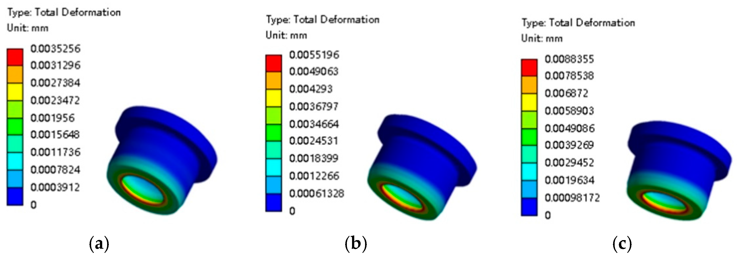
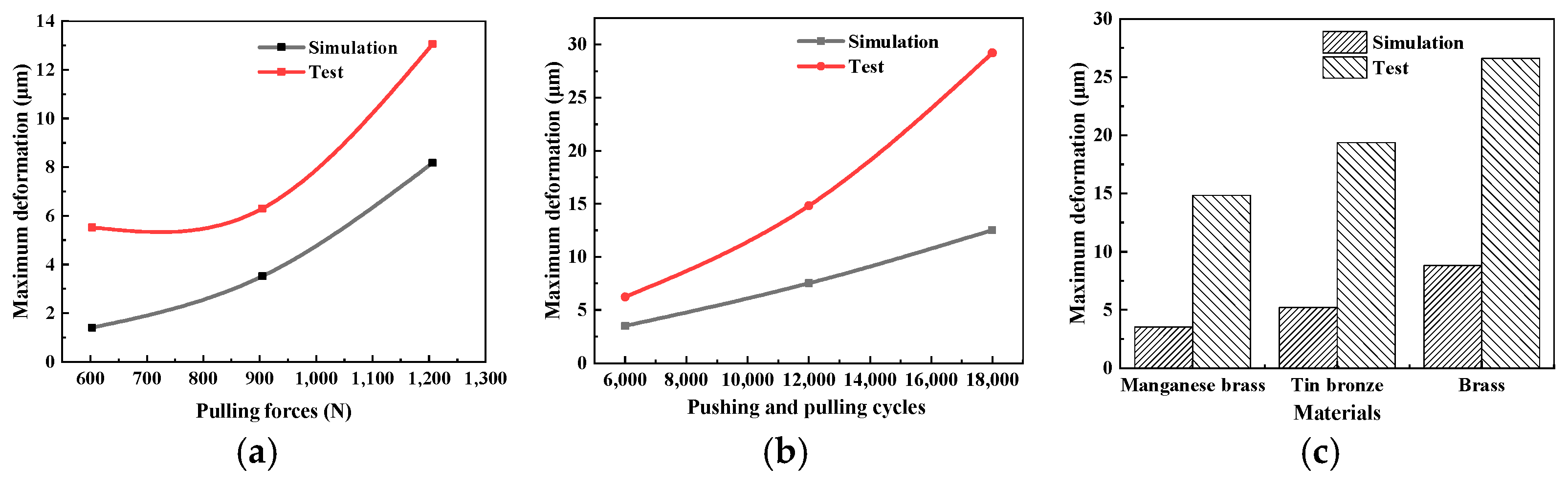
We aggregated the simulation and test results for slipper deformation under various factors, and the maximum deformation curve of the slipper with respect to pushing and pulling forces and the pushing and pulling cycle was obtained, as shown in
Figure 17a,b. The simulation and test results of the maximum deformation of the slippers with different materials are presented in
Figure 17c.
It can be seen from
Figure 19 that with the increase in the pushing and pulling force and the number of cycles of pushing and pulling, the deformations obtained by simulations and testing both increase accordingly. Moreover, the relationship between the maximum deformation of the slipper and the pushing and pulling force is nonlinear, while the relationship between the maximum deformation of the slipper and the pushing–pulling cycle count is approximately linear.
Meanwhile, it is also clear that for different pushing and pulling forces and cycle counts, the deformation obtained from the tests is greater than the simulation values. When the pushing and pulling forces are 603.18 N, 904.78 N, and 1206.37 N, the differences between the test and simulation results of the maximum deformation are 4.1179 μm, 2.7792 μm, and 4.8834 μm, respectively. And when the pushing and pulling cycle counts are 6000, 12,000, and 18,000, the differences between the tests and simulations are 2.7192 μm, 7.3044 μm, and 16.6742 μm, respectively. The test and simulation results both show that the deformation increases from the manganese brass slipper to the tin bronze slipper to the ordinary brass slipper. Therefore, in a working environment with high rotational speeds and high pressures, it is necessary to select materials (such as manganese brass) that have both a high elastic modulus and a high yield strength to ensure that the spherical joint pairs have sufficient deformation resistance and reliability. Here, there is also a phenomenon where the test results are greater than the simulation results.
The reasons why the test results of the deformation were greater than the simulation results are as follows:
- (1)
The modeling assumptions have limitations. The strength simulation of the spherical joint pair only considers the strength of the piston and the slipper and does not account for the wear between the piston and the slipper. At present, there is no robust calculation method that considers both strength and wear, which may cause the simulation results to be smaller than the experimental results.
- (2)
There are processing and assembly errors in the piston–slipper kits used in the test. Due to the limitations of the processing equipment, it is impossible to create ideal surfaces for the piston ball head and the slipper ball socket. There will always be minor deviations when the piston and slipper are assembled. Because of this, during the pushing and pulling process, uneven stress distribution will occur, resulting in an increase in the maximum deformation of the slipper ball socket.
6. Conclusions
An axial piston pump’s piston-returning spherical joint pair bears alternating high–low pressure loads. Insufficient slipper–piston assembly strength impacts pump operation. Via numerical simulations and tests, we determined how different pushing–pulling forces, pushing–pulling times, and slipper materials affected slipper–piston deformation.
- (1)
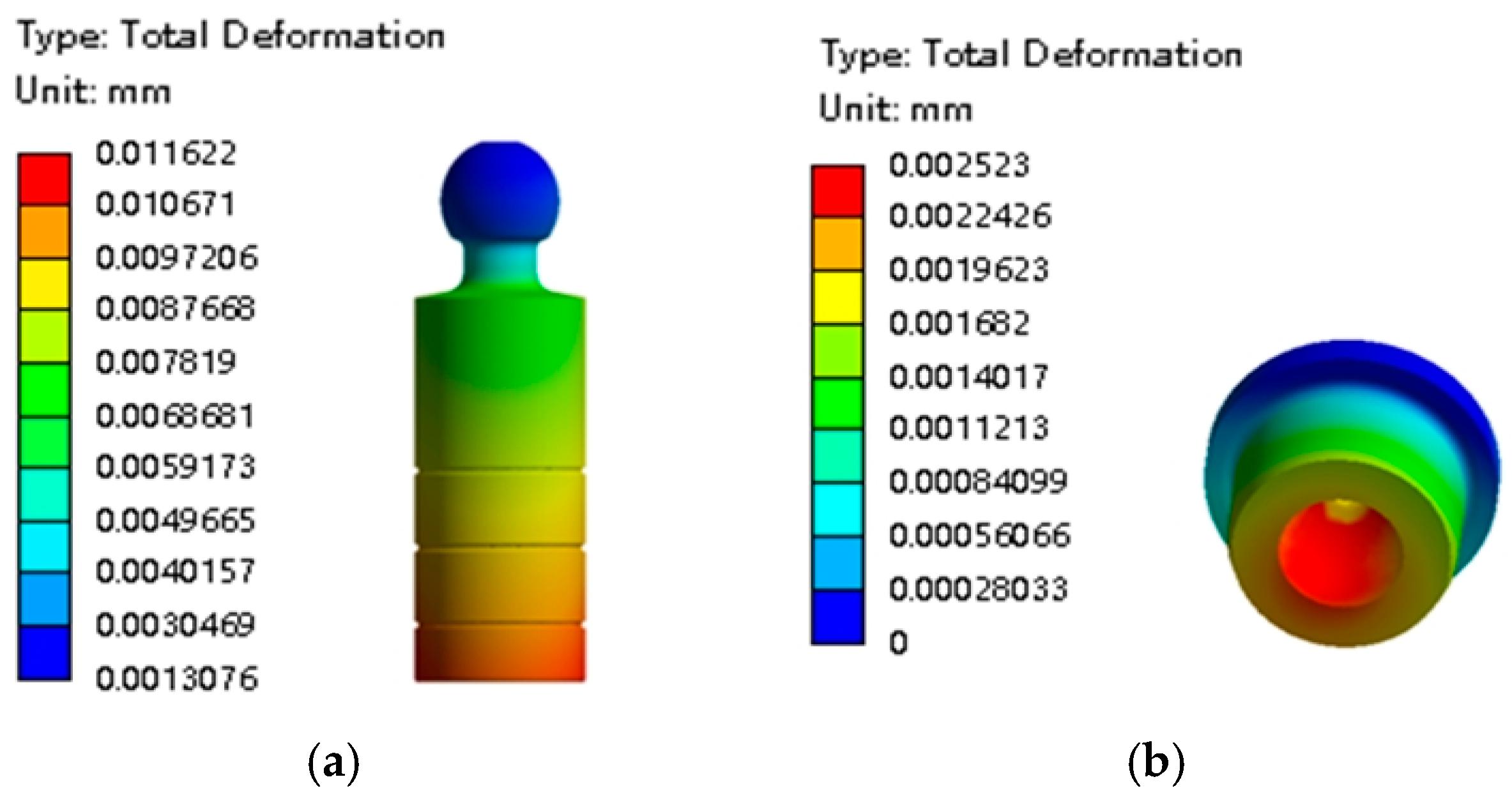
When the piston enters the oil discharge area from the oil suction area, the maximum deformation and maximum stress of the slipper are located on the inner surface of the slipper ball socket and are 2.523 μm and 126.23 MPa, respectively. The maximum deformation of the piston is 11.622 μm.
- (2)
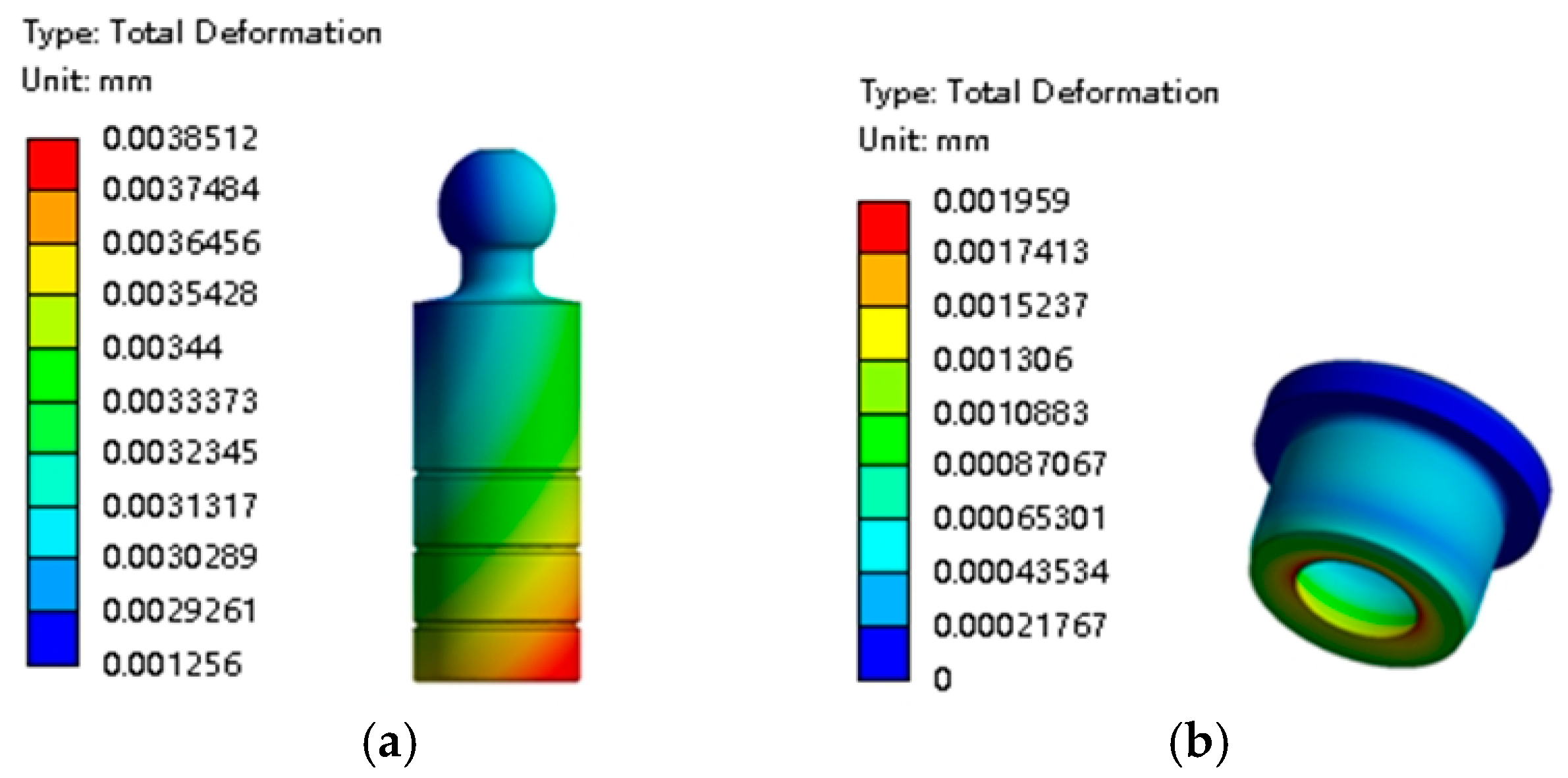
When the piston enters the oil suction area from the oil discharge area, the maximum deformation and maximum stress of the slipper occur at the spherical socket closure and are 1.959 μm and 63.582 MPa, respectively. The maximum deformation and maximum stress of the piston are 3.8512 μm and 31.815 MPa, respectively.
- (3)
The deformation at the spherical socket closure of the slipper increases with the pushing and pulling force, and the number of pushing and pulling cycles; this relationship is nonlinear. The maximum deformation at the spherical socket closure also varies depending on the slipper material. Furthermore, the test results are higher than the simulation results.
The findings of this study offer several significant benefits. Firstly, it will enhance the understanding of the failure mechanisms of piston-returning spherical joint pairs in high-speed axial piston pumps, enabling the development of more effective preventive measures. Secondly, this study will provide valuable insights toward the optimal design of joint pairs, which can lead to improved pump performance, increased reliability, and extended service life.
In future research, the author plans to optimize the simulation model by taking into account the complexity of the material’s microstructure and the dynamic changes in factors such as temperature and corrosion in the working environment. More complex algorithms and additional computational resources will be utilized to enhance the accuracy of the simulation model. Additionally, the testing equipment will be improved to reduce errors and interference factors during the testing process. These efforts are designed to enhance our understanding of the strength characteristics of the piston-returning spherical joint pair.


