Article

Abrasive Flow Material Removal Mechanism Under Multifield Coupling and the Polishing Method for Complex Titanium Alloy Surfaces

1
College of Mechanical Engineering, Zhejiang University of Technology, Hangzhou 310014, China
2
Key Laboratory of Special Purpose Equipment and Advanced Processing Technology, Ministry of Education & Zhejiang Province, Zhejiang University of Technology, Hangzhou 310014, China
3
Hangzhou Leban Intelligent Technology Co., Ltd., Hangzhou 310000, China
*
Authors to whom correspondence should be addressed.
Processes 2025, 13(2), 416; https://doi.org/10.3390/pr13020416
Submission received: 11 November 2024 / Revised: 14 January 2025 / Accepted: 26 January 2025 / Published: 5 February 2025
(This article belongs to the Section Materials Processes)

Abstract

:
This study addresses the challenge of uneven surface quality on the concave and convex regions during the precision machining of titanium alloy thin-walled complex curved components. An electrostatic field-controlled liquid metal-abrasive flow polishing method is proposed, which is examined through both numerical simulations and experimental investigations. Initially, a material removal model for the liquid metal-abrasive flow under electrostatic field control is developed, with computational fluid dynamics (CFD) and discrete phase models employed for the numerical simulations. Subsequently, the motion characteristics of liquid metal droplets under varying amplitudes of alternating electric fields are experimentally observed within the processing channel. This serves to validate the effectiveness of the proposed method in enhancing surface quality uniformity across the concave and convex regions of titanium alloy thin-walled complex curved components. Our results demonstrate that by controlling the distribution of the electric field in regions with varying flow strengths, the roughness differences between the concave and convex surfaces of the workpiece are reduced to varying degrees. Specifically, in the experimental group subjected to a 24 V alternating electric field, the roughness difference is minimized to 58 nm, representing a 44% reduction compared to conventional abrasive flow polishing. These findings indicate that the proposed electrostatic field-controlled liquid metal-abrasive flow polishing method significantly enhances the uniformity of surface polishing on concave and convex areas of titanium alloy thin-walled complex curved components.

1. Introduction

Titanium alloys are widely employed in the fabrication of complex curved thin-walled components due to their exceptional properties, including high strength, excellent corrosion resistance, favorable biocompatibility, and good formability. These alloys are particularly suited for applications requiring high performance, lightweight design, and enhanced durability, making them ideal for use in defense, aerospace, and biomedical engineering [1,2,3]. Notable examples of such applications include turbine engine blades, artificial joint surfaces, and propeller blades [4,5,6].
Polishing methods for complex titanium alloy thin-walled components include traditional mechanical polishing [7,8,9,10], laser polishing [11,12,13], electrochemical polishing [14,15,16,17,18], pneumatic polishing [19,20,21], and robotic polishing [22,23,24]. Among these techniques, the robotic control of pneumatic abrasive wheels has demonstrated a significant reduction in processing time when applied to the polishing of titanium alloy aerospace engine blades. However, the occurrence of tool vibration during the process can negatively impact the overall machining quality [25]. Pakin et al. [26] investigated the use of nanosecond pulsed laser polishing for titanium alloy workpieces, reporting that a laser energy density of 1 to 3 J/cm² resulted in a reduction of surface roughness by approximately 43%. Despite these advantages, laser polishing is associated with high equipment costs and stringent requirements regarding the material’s heat-affected zone, which may lead to local overheating or deformation [27,28]. Zaborski employed electrochemical polishing on titanium alloy total hip prostheses, achieving a surface roughness of approximately Ra = 0.05 to 0.15 μm. Compared to mechanically ground surfaces, the electrochemically polished surfaces exhibited a 25 to 30% increase in surface activity, along with a 20% higher glossiness relative to mechanically polished counterparts [21]. However, electrochemical polishing requires precise control over the composition and flow dynamics of the electrolyte, imposes demanding operational conditions, and is associated with relatively low polishing efficiency [29].
Abrasive flow polishing (AFP) technology employs a semisolid abrasive medium with adhesive characteristics, which, under the action of external driving forces, moves reciprocally across the workpiece surface to achieve a polishing effect [30,31]. In the context of polishing titanium alloy thin-walled curved components, AFP offers distinct advantages due to its capacity to conform to complex geometries and preserve superior surface integrity. Furthermore, it is particularly effective in reaching and polishing areas that are difficult to access, thereby distinguishing it from other polishing techniques [32]. However, current AFP methods face challenges when applied to thin-walled curved surfaces with significant curvature variations. Specifically, the material removal rate remains inconsistent across the uneven surfaces of the workpiece, hindering the achievement of high-precision polishing for such complex geometries [33]. Surface roughness affects the behavior of liquids on these surfaces. The greater the complexity of the surface, the lower the wetting [34].
Liquid metal is a promising material that combines the inherent properties of metals with the fluidic behavior of liquids, garnering significant attention in various research domains and industrial applications due to its unique characteristics, including high thermal conductivity, exceptional wettability, and superior fluidity [35,36,37]. The electrostatic field-controlled liquid metal-abrasive flow polishing method proposed in this study focuses on titanium alloy thin-walled complex curved components, utilizing liquid metal as the driving medium. By exploiting the electromechanical properties of liquid metals [38], this method enables precise control of liquid metal motion through the strategic distribution of electric fields within the abrasive flow channel, thereby enhancing the uniformity of surface quality across both concave and convex areas of curved surfaces. When compared to conventional methods such as mechanical polishing, electrochemical polishing, and laser polishing, the liquid metal-abrasive flow polishing technique offers distinct advantages [39,40,41].
First, by precisely controlling the movement of abrasive particles via the electric field, this method achieves superior precision and uniformity, effectively reducing variations in surface roughness on curved workpieces. In contrast, traditional methods, which rely on physical contact, are prone to creating uneven surfaces or inducing localized over-polishing. Second, the proposed method demonstrates enhanced applicability in the processing of complex curved surfaces and thin-walled components, particularly when polishing difficult-to-machine materials such as titanium alloys, where conventional methods often fail to deliver optimal results [42,43]. Furthermore, liquid metal-abrasive flow polishing is more environmentally sustainable. By adjusting both the liquid and electric field parameters, this approach reduces the generation of waste materials and harmful gases, leading to a lower environmental impact compared to traditional mechanical or chemical polishing techniques [44,45].
This study proposes a novel and controllable liquid metal abrasive flow polishing technique, providing a new approach for efficient, low-stress processing of titanium alloy thin-walled curved workpieces. It addresses the shortcomings of other polishing methods in terms of polishing uniformity and workpiece surface quality control while revealing the intrinsic relationship between processing parameters and surface quality. The findings of this research have the potential to advance the manufacturing of high-value-added components in fields such as aerospace and biomedicine, enhancing product performance and lifespan. Additionally, it aligns with the trends of green manufacturing and intelligent production, laying a theoretical and technological foundation for the development of complex curved surface machining technologies. This work holds significant academic value and application prospects.

2. Theoretical Models

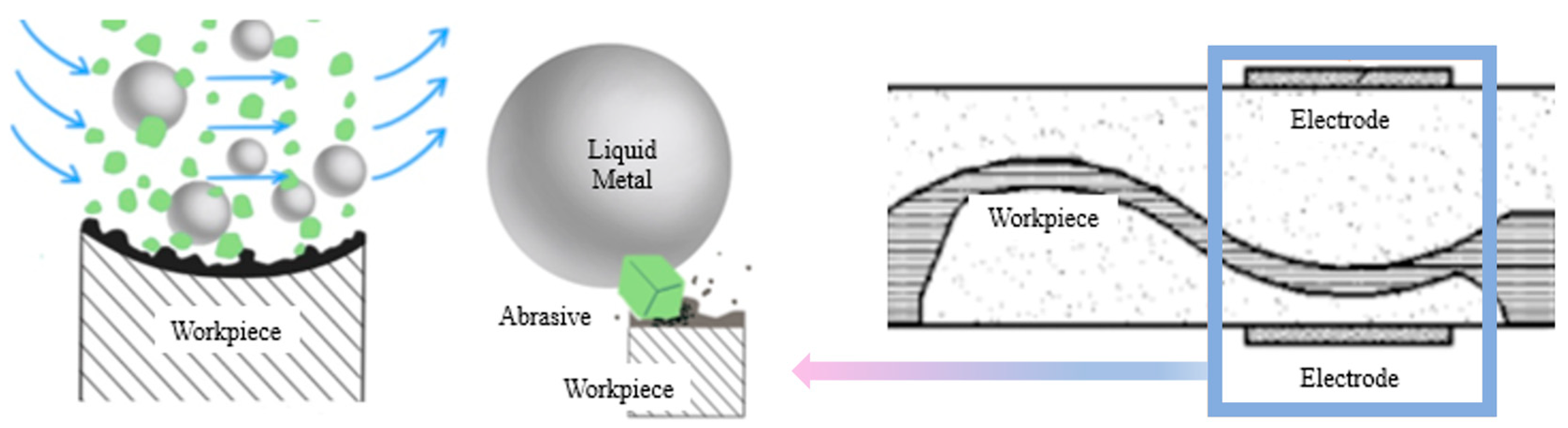
2.1. The Principle of the Liquid Metal Mixed Abrasive Flow Polishing

The macroscopic motion of liquid metal droplets under an electric field is driven by changes in the surface tension gradient induced by the applied electric field. When gallium-based liquid metal is exposed to air, it quickly reacts with the oxygen in the atmosphere, forming a very thin oxide layer (Ga2O3) on its surface. Ga2O3 is a white crystalline solid that is insoluble in water but soluble in alkaline solutions. As a result, when gallium-based liquid metal comes into contact with a NaOH solution, the oxide layer reacts with the NaOH, producing Ga(OH)3. These ions impart a significant negative charge to the surface of the liquid metal droplet, leading to the formation of a double electric layer as these negative charges interact with free ions in the surrounding solution. In the absence of an external voltage, the negative ions are uniformly distributed across the surface of the liquid metal droplet, as shown in Figure 1a, resulting in a symmetric surface tension.
When an external electric field is applied, the charges on the surface of the liquid metal redistribute due to its high electrical conductivity, reaching an electrostatic equilibrium. Since the surface tension of the liquid metal decreases with increasing electric potential, the surface tension near the cathode becomes higher than that near the anode. When the difference in surface tension between the two ends exceeds the resistive forces due to viscosity and friction, the liquid metal droplet rapidly moves toward the anode, as illustrated in Figure 1b.
During the liquid metal abrasive flow polishing process, abrasive particles move randomly within the flow channel under the influence of a turbulent liquid-phase carrier. The turbulence energy of the fluid determines the cutting performance of the abrasive particles [46,47]. In the case of free-curvature titanium alloy curved workpieces, the structural characteristics lead to uneven turbulence in the flow field across different regions of the workpiece, resulting in variations in surface roughness after processing.
Figure 2 illustrates the principle of liquid metal mixed abrasive flow polishing controlled by an electric field. As shown in the figure, applying an alternating electric field in regions with weak flow causes voltage variations that alter the electrostatic driving effect of the liquid metal. This, in turn, affects the distribution, movement trajectories, and interactions of the abrasive particles with the workpiece surface. Specifically, as the alternating voltage increases, the electric field force may enhance the flowability of the liquid metal, further influencing the impact force and distribution of the abrasive particles. Higher voltage levels can cause the abrasive particles to focus more densely on the workpiece surface, leading to increased material removal in localized areas and resulting in lower surface roughness.
However, excessively high voltage may cause an uneven distribution of the liquid metal and abrasive particles, leading to nonuniform abrasive impacts, which could, in turn, increase surface roughness. Li et al. [39] noted in their study that the electric field not only affects the flow pattern of the liquid metal but also modifies the kinetic energy of the abrasive particles and the material removal mechanism, thereby significantly influencing the surface roughness. Moreover, the placement of the electric field is also critical, as it can affect the polishing performance of the liquid metal mixed abrasive flow.

2.2. The Mixture Turbulence Model

The liquid metal-particle flow is a mixture model composed of liquid metal particles, abrasive particles, and the liquid base medium. In this model, the liquid base medium serves as the continuous phase, while the abrasive particles and liquid metal particles constitute the dispersed phases in a low proportion. The Mixture model is a simplified Eulerian multiphase flow model that can be used to simulate multiphase flows with different velocities, suitable for low-load particle flows [48]. Therefore, in this paper, the Mixture multiphase flow model is selected to study the mass transfer process in liquid metal-particle flows. Its continuity equation is as follows:
( ρ m ) t + ( ρ m v m ) = 0
where vm is the mass-averaged velocity and ρm is the density of the mixture, as follows:
v m = k = 1 n a k ρ k v k ρ m
ρ m = k = 1 n a k ρ k
where αk is the volume fraction of phase k.
( ρ m v m ) t + ( ρ m v m v m ) = p + [ μ m ( v m + ( v m ) T ) ] + ρ m g + F k = 1 n a k ρ k v k v k
where p is the pressure, μm is the viscosity of the mixture, g is the gravitational acceleration, F is the body force, and vk is the drift velocity of the secondary phase k, expressed as follows [38]:
v d , k = v k v m
The energy equation for the mixture is as follows:
t k α k ρ k E k + k α k ρ k v k ( E k + p ) = ( k e f f T ) k , j h j , k J j , k + ( k e f f T ) + S n
where the first three terms of Equation (7) represent the energy transfer due to conduction, mass diffusion, and viscous dissipation, respectively. Sh represents other heat sources, and Ek is the energy of phase k, expressed as follows:
E k = h k p ρ k + v 2 2
where hk represents the sensible enthalpy of phase k, hj,k is the enthalpy of substance j in phase k, Jj,k is the diffusion flux of substance j in phase k, T is the temperature, and keff is the effective thermal conductivity, expressed as follows:
k e f f = k α k ( k k + k l )
where kt is the turbulent thermal conductivity defined according to the turbulence model used.
Based on the above Mixture turbulence model, the n-phase multiphase flow is simulated by solving the momentum, continuity, and energy equations for the mixture, along with the volume fraction equation for the secondary phases and the algebraic expression for the relative velocity. The flow field evolution in the liquid metal-particle flow is accurately solved, yielding the motion trajectories of the abrasive particles and the energy transfer process under the influence of the flow field.

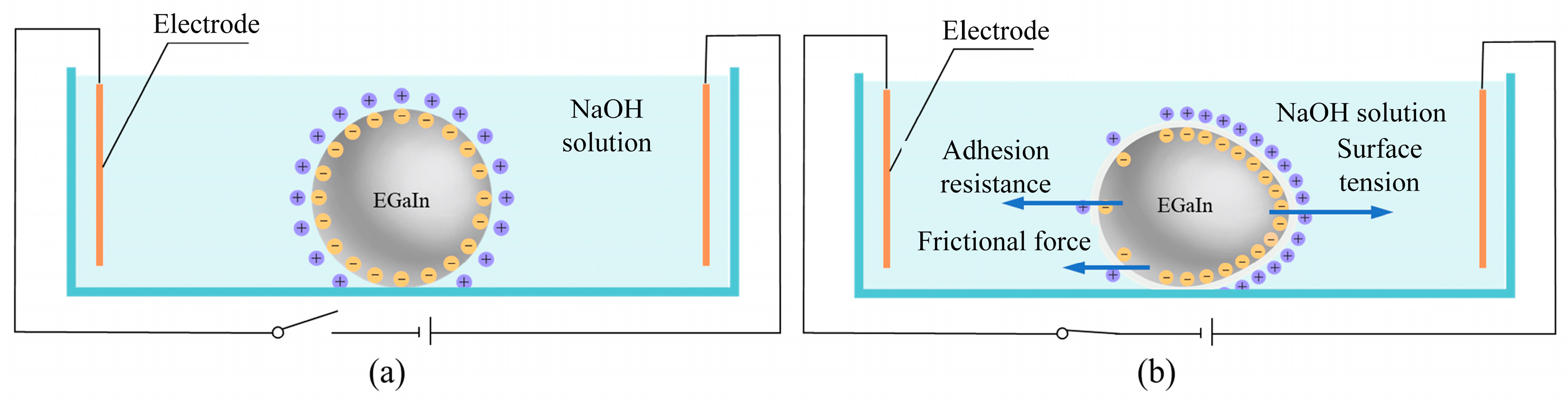
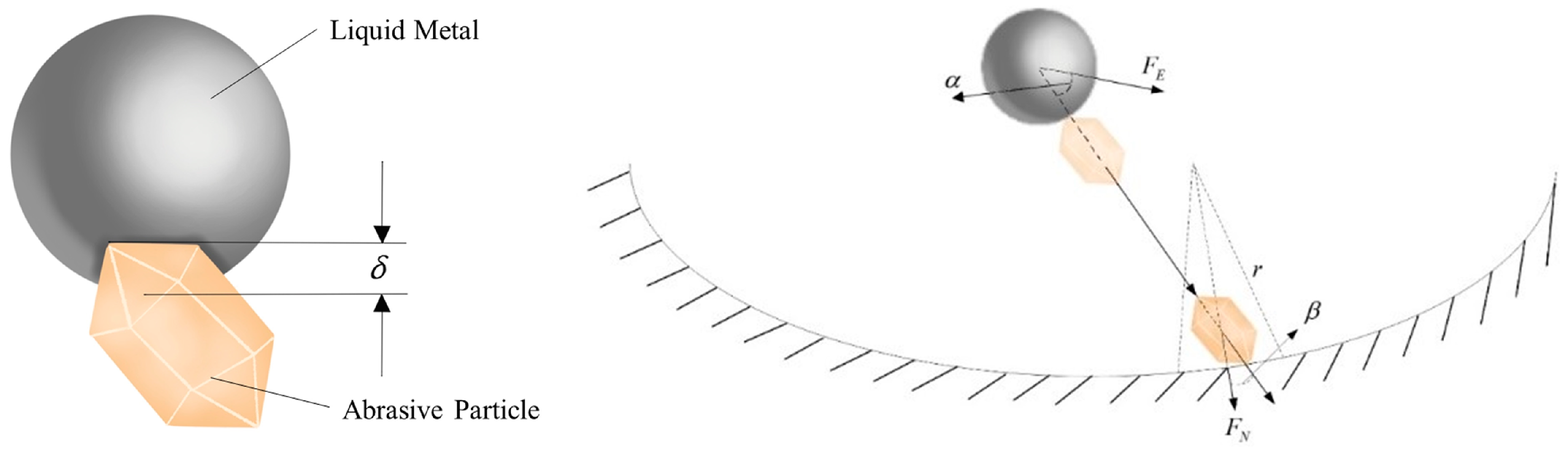
2.3. The Contact Model Between Liquid Metal and Abrasive Particles Under Electric Field

The macroscopic motion of liquid metal droplets under an electric field is caused by changes in the surface tension gradient of the liquid metal induced by the applied electric field. When the external electric field is applied, the charge distribution on the surface of the liquid metal rearranges to reach an electrical equilibrium state. The Lippmann equation is as follows:
γ = γ 0 c V 2 2
where γ is the surface tension, V is the electric potential, c is the capacitance of the double electric layer, and γ0 is the maximum surface tension of the metal droplet when the electrode voltage is zero. The surface tension near the cathode is greater than that near the anode. When the surface tension difference caused by the variation in surface tension exceeds the viscous resistance and frictional forces, the liquid metal droplet will rapidly move toward the anode.
When subjected to an electric field, the surface elements of the droplet experience the pressure difference between the liquid metal pressure and the NaOH solution pressure. According to the Young-Laplace equation, the surface pressure difference ΔPk is as follows:
Δ P k = P LM - P NaOH = 2 γ k R
where PLM is the pressure of the liquid metal, PNaOH is the pressure of the NaOH solution, γk is the surface tension at the surface element, and R is the curvature radius of the droplet surface, with the pressure direction pointing towards the center of the sphere. The surface potential difference for each element Vk is as follows:
V k = V 0 + Δ u k
where V0 = q/c represents the initial potential, q is the initial charge in the double electric layer, and Δuk is the change in the double electric layer potential difference at the surface element due to the applied external electric field. The surface tension is expressed as follows:
γ k = γ 0 1 2 c V k 2 = γ 0 1 2 c ( V 0 + Δ u k ) 2
The external application is an AC electric field, so the liquid metal surface is an inductive electric double layer, and the potential difference change is as follows:
Δ u k = 1 1 + δ Re ( ( ϕ ˜ A C ϕ ˜ A C o ) e j ω t )
where εs is the surface capacitance ratio, ϕ ˜ A C is the alternating potential of the induced double electric layer, ϕ ˜ A C o is the potential of the liquid metal body, and ω is the frequency of the alternating current signal. The electric field driving force on the liquid metal droplet is as follows:
F E = i = 1 n Δ P k S n = i = 1 n [ 2 γ 0 c ( q c + 1 1 + δ Re ( ( ϕ ˜ A C ϕ ˜ A C o ) e j ω t ) ) 2 ] S R n
where S is the surface area of the liquid metal droplet, and n is the number of surface elements on the liquid metal droplet, each with the same area and capacitance. Based on Hertzian contact theory, the normal force is linearly related to the 1.5 power of the superposition amount. Therefore, the normal force acting on the abrasive particle is as follows:
F n = ( k n δ 1 . 5 η n G n ) n
where kn is the normal elastic coefficient, G is the relative velocity between the two droplets, and ηn is the normal damping coefficient. Assuming that there is no slip between droplets and abrasive particles during the collision, the tangential force can be expressed as follows:
F t = k t δ t η t G t
where kt is the tangential elastic coefficient, G t is the tangential relative velocity between the two, and ηt is the tangential damping coefficient.
If there is a slide between the two during the collision, the tangential force is expressed as follows:
F t 1 = f F n t
where f is the coefficient of friction between the two droplets t = G t / G t . Therefore, the kinematic model of the abrasive particles in the liquid metal-particle flow can be expressed as follows:
m p d v p d t = F i = F g + F b + F D + F p + F v m + F B + F M + F s + F n + F t
However, since the pressure gradient force, the fictitious mass force, the Basset force, and the Saffman lift are relatively small and can be neglected, the simplified kinematic model for the liquid metal-particle flow is expressed as follows:
m p d v p d t = F i = F g + F b + F D + F M + F n + F t
where mp is the mass of the abrasive particle, vp is the velocity of the droplet, t is time, g is the gravitational force, Fb is the buoyancy force, FD is the drag force, FM is the Magnus lift force, Fn is the normal force exerted by the liquid metal droplet on the abrasive particle, and Ft is the tangential force exerted by the liquid metal droplet on the abrasive particle.
Based on the above metal droplet-abrasive particle contact model, the electric field driving force equation and Hertzian contact theory are applied to describe both the nonslipping and slipping collision processes between the metal droplet and the abrasive particles. The dynamic model of the abrasive particles in the liquid metal particle flow is simplified and provides the force conditions acting on the particles, thus forming the basis for further investigation of the material removal mechanism.

2.4. The Material Removal Mechanism Under Multifield Coupling

To study the machining mechanism of the workpiece being processed, the material removal mechanism on the workpiece surface requires further investigation. Based on the Mixture multiphase flow model and the contact model of liquid metal and abrasive particles in an electric field, this paper analyzes the elastic collision process and cutting action of abrasive particles near the wall region on the workpiece surface under the combined effects of the flow field and electric field. The mechanism of material removal from workpiece surfaces under the multi-physics field coupling is explored. The Preston material removal model is expressed as follows:
Δ z = 0 t k p p v d t
where ∆z is the material removal rate, p is the relative pressure of the abrasive particles in the near-wall region, v is the relative velocity of the abrasive particles in the near-wall region, and kp is the proportional constant.
In the flow field, due to the influence of multiple forces, the abrasive particles undergo random motion on the workpiece surface. The cutting action of the abrasive particles primarily occurs during the elastic deformation process, and the contact pressure is expressed as follows:
P a v = 4 E F N 3
where FN is the normal contact force, and E∗ is the elastic contact modulus between the abrasive particle and the workpiece, expressed as follows:
E = 1 1 μ 1 2 E 1 + 1 μ 2 2 E 2
where E1 and E2 are the elastic moduli of the abrasive particle and the workpiece, respectively, and μ1 and μ2 are the Poisson’s ratios of the abrasive particle and the workpiece, respectively.
The abrasive particles are impacted toward the surface of the workpiece by collision with the liquid metal, as shown in Figure 3 [49].
For ease of calculation, the fluid resistance is ignored, and the force between the abrasive particle and the surface of the workpiece is expressed as the force between the metal droplet and the abrasive particle. The normal contact force exerted by the abrasive particles on the workpiece surface is as follows:
F N = F E cos α cos β
where FE is the total force exerted by the liquid metal droplet on the abrasive particle, expressed as follows:
F E = F n + F t
where α is the angle between the direction of the motion of the abrasive particle and the direction of the force of the metal droplet on the abrasive particle, and β is the angle between the force of the abrasive particle on the surface of the workpiece and the normal direction. Based on the Equations (21)–(24), the contact pressure after the collision is expressed as follows:
P a v = 4 E ( F n + F t ) cos α cos β 3
Assuming that there is no rotation of the liquid droplet or abrasive particle during the collision and that the tangential components of the velocity remain unchanged before and after the collision, the velocity of the abrasive particle after the collision vp and the velocity v∗ when it contacts the wall are expressed as follows:
v p = v p m m p ( 1 + e ) ( v 3 n ) n
v = v p cos θ
where m∗ represents the effective mass, is the restitution coefficient, e is the mass of the abrasive particle, and θ is the angle between the direction of the abrasive particle motion after the collision and the tangential direction at the point of contact with the workpiece.
Δ z = 0 t k 1 k 2 4 × 3 1 2 E ( i = 1 n [ 2 γ 0 c ( q c + 1 1 + δ Re ( ( ϕ ˜ A C ϕ ˜ A C o ) e j ω t ) ) 2 ] S R n ) cos α cos β ( v p m m p ( 1 + e ) ( v 3 n ) n ) cos θ d t
where k1 and k2 represent the first and second coefficients, E∗ is the elastic contact modulus between the abrasive particle and the workpiece, δ is the surface capacitance ratio, vp is the velocity of the abrasive particle before the collision, and v3 is the velocity of the liquid metal droplet relative to the abrasive particle.
Based on the single-droplet material removal model for the liquid metal–abrasive particle flow processing method under the electric field control, the collision and material removal process on the workpiece surface was analyzed under the multifield coupling. This model provides theoretical guidance for subsequent workpiece processing and offers technical support for related research.

3. Numerical Model

Under the multifield coupling, the collision process between liquid metal droplets and abrasive particles inside the flow channel exhibits highly nonlinear characteristics [50]. To study the motion behavior of metal droplets and abrasive particles, as well as the collision-based material removal mechanism in the multifield coupling, a liquid metal–abrasive particle flow coupled processing model under the influence of an applied electric field has been established, as shown in Figure 4. The workpiece to be processed is a titanium alloy with a complex curvature, as depicted in Figure 4a. The flow direction on the surface of the titanium alloy workpiece is shown in Figure 4b. In the overall processing model, the flow channel structure is designed to resemble a Venturi tube, as shown in Figure 4c. The geometric parameters of the overall processing model are listed in Table 1. In the processing device, the metal droplets and abrasive particles enter from the left side along with the base solution, pass through the tapered acceleration region, and then enter the processing area. In the processing area, the electric field drives the liquid metal droplets to collide with the abrasive particles. After the collision with the metal droplets, the abrasive grains undergo a collision and material removal process with the workpiece and finally leave the machining area from the right-hand flow channel. The distribution law of metal droplets and abrasive particles in the flow field of the base liquid and the collision behavior under the action of the electric field are investigated based on the above model.
In the multifield coupling model, the quality of the mesh is crucial for both the accuracy of the results and the computational efficiency [51,52]. In regions where the velocity gradient of the flow field and the coupling between the electric field and particles are significant, mesh refinement is required to improve the connectivity and stability of the mesh. In this study, The COMSOL Multiphysics 5.4 software is used to discretize the multifield processing model, as shown in Figure 5. The mesh density is increased in the processing area flow field to account for the collision processes between the metal droplets and abrasive particles, as well as the interactions between the abrasive particles and the workpiece. The refinement enhances the accuracy of the coupling calculations and improves the convergence of the numerical solution.
The mesh quality can be assessed using various standards, with skewness being applicable to most mesh types. The quality measurement is based on the angular skewness ratio, which evaluates how far the angles of the mesh elements deviate from the ideal case. The skewness tool was employed in this study to assess the mesh quality, as shown in Figure 6. For mesh quality measurement, a value of 1 indicates the best quality, meaning the elements meet the highest standard of the selected quality measure. Conversely, a value of 0 indicates a degenerated element. Based on viewpoints 1 and 2, the overall mesh quality is good. Therefore, the calculation achieves both high accuracy and improved efficiency at this mesh density.
In the numerical calculation process, the basic simulation parameters are shown in Table 2. The surface tension driving force on the liquid metal comes from the surface tension difference caused by the uneven distribution of the electric potential. Combined with the electric field potential distribution in the processing flow channel and the small volume fraction of abrasive particles in the abrasive flow, the model is simplified as follows: (1) ignore the influence of particles on the fluid; (2) ignore the shape change of liquid metal particles and treat the shape as a sphere; (3) mainly consider the influence of gravity, drag, and liquid metal particle impact force on the abrasive particles.
In the simulation, liquid metal droplets are simplified to a spherical shape to enable more efficient calculations. This assumption is grounded in the physical properties of liquid metal, which, due to its high surface tension, naturally tends to form spherical shapes in the absence of significant external disturbances. Consequently, under certain conditions—such as when strong flow fields or external forces are not present—spherical droplets can effectively approximate the actual shape of liquid metal, making this simplification highly relevant in specific scenarios. In real-world experiments, the size of liquid metal droplets is typically small, and surface tension becomes the dominant force governing their shape. At such scales, the spherical assumption aligns well with observed behavior, further validating its applicability.

4. The Abrasive Particle Motion and Material Removal Mechanism

The abrasive particle flow is a mixture of liquid composed of a liquid phase carrier and abrasive particles. Figure 7 illustrates the motion process of the abrasive particle flow entering from the left inlet, from 0 s to 0.13 s. In Figure 7, red represents the abrasive particle flow, and blue represents water. The area between the red and blue colors represents the mixed region of abrasive particle flow and water, where the concentration of abrasive particles decreases due to the dilution of the flow by water. The abrasive particle flow enters from the left inlet and gradually fills the entire flow channel over time. As seen in Figure 7f, when t = 0.13 s, the abrasive particle flow fills the entire flow channel. It indicates that the abrasive particle flow is in full contact with the processing surface, meaning that the flow field of the abrasive particle flow reaches a steady state at this moment.
The externally applied electric field in this paper is an AC electric field with voltages of 6 V, 12 V, 24 V, and 36 V. The alternating electric field, as a vector field, directly affects the motion trajectory of liquid metal particles. Since the alternating electric field is constantly changing, the motion trajectory of the liquid metal is influenced not only by the amplitude of the alternating electric field but also by the instantaneous electric field when the liquid metal enters the field. In this study, the COMSOL Multiphysics 5.4 software fluid flow particle tracking interface, combined with the multiphase fluid model and alternating electric field model, is used to obtain the motion trajectories of liquid metal particles entering from the inlet 1 under different alternating voltages, as shown in Figure 8. In the absence of an applied electric field, the metal droplets follow the flow field distribution through the processing area and exit the processing zone from the right side of the model. As the voltage increases to 6 V, only a portion of the metal droplets’ motion trajectories do not come into contact with the workpiece and leave the flow field directly, which indicates that the participation rate of these metal droplets in the processing is low at this point. It is observed that as the voltage increases, the motion trajectories of the droplets show more intense collisions with the workpiece, with all the metal droplet trajectories intersecting with the surface of the workpiece. It suggests the increased participation rate of the metal droplets in the processing, which accelerates the material removal rate. The above results show that the applied AC electric field promotes the contact between the particles and the surface to be processed and improves the processing efficiency.
This study employs the Preston material removal model as a theoretical foundation, considering the relationships among material removal, various process parameters, and abrasive characteristics. By incorporating the motion characteristics of abrasives in the liquid metal-abrasive flow, this research analyzes the effects of abrasives on the workpiece surface. This analysis takes into account abrasive features, contact pressure near the wall, and relative motion speed. This investigation contributes to the development of a comprehensive material removal model specific to the liquid metal-abrasive flow. This model emphasizes the dependencies on factors such as the AC electric field, abrasive contact pressure, and abrasive cutting speed.
Considering the characteristics of the electric field potential distribution in the machining channel and the low volume fraction of abrasive droplets in the abrasive flow, the model is simplified as follows: the impact of droplets on the fluid is disregarded. The shape changes of liquid metal droplets are neglected, and they are treated as spherical. The analysis primarily focuses on the effects of gravity, drag force, and the impact force of liquid metal droplets on abrasives. This study employs the Preston material removal equation to assess the impact of liquid metal droplets on the workpiece surface. This impact is quantified by considering the pressure on the workpiece surface and the product of the abrasive flow velocity passing through it. To simplify the model, the following assumptions are made: The influence of droplets on the fluid is neglected. Liquid metal droplets are assumed to be spherical. The primary factors considered are gravity, drag force, and the impact force of liquid metal droplets on abrasives.
The machining area is divided into two distinct zones: Zone I; The convex region, characterized by a narrower channel and higher overall fluid velocity, resulting in greater kinetic energy of abrasives. This is defined as the strong flow field region. Zone II; The concave region, defined as the weak flow field region due to its wider channel and, consequently, lower fluid velocity. Within these zones, specific areas are identified: Gate 1, The area near the entrance of Zone I. Gate 3, The area near the entrance of Zone II. This zonal classification allows for a more nuanced analysis of the material removal process, taking into account the varying flow characteristics in different regions of the workpiece surface, as shown in Figure 9.
Under the influence of an alternating electric field, liquid metal droplets induce an accelerated motion of abrasives in the weak flow field. This acceleration leads to frequent collisions between abrasives and the workpiece surface, thereby enhancing the Pv value in the near-wall region of the workpiece within the weak flow field. This study simulates the liquid phase motion of liquid metal droplets from inlet 1 to outlet 3 using a representative 6 V alternating voltage. The simulation yields the variation of the Pv value as the droplets pass over the workpiece surface. Figure 10 illustrates this process; the red portion represents liquid metal droplets, the blue portion represents abrasive flow fluid, and the white portion indicates the interface between liquid metal droplets and abrasive flow fluid.
In Region II, liquid metal droplets traverse from position a to position f in the sequence a-b-c-d-e-f, influenced by the combined effects of the flow field and electric field. During this motion, the droplets collide with surrounding abrasives, consequently affecting the Pv variation in the near-wall region of the workpiece. Figure 11 illustrates this Pv variation. As the liquid metal droplets travel along the sequence, they collide with the abrasives. These collisions are crucial because they transfer kinetic energy to the abrasives, affecting the overall dynamics of the material removal process. The impact of the droplets on the abrasives can lead to changes in the local Pv, particularly in the near-wall region of the workpiece. The trend of the Pv value during the movement of abrasive grains in the machining area is shown in Figure 11. The near-wall region is where the material removal is most concentrated, and any changes in the Pv in this area can directly influence the efficiency and quality of the polishing or machining process.
The influence of varying alternating electric fields on droplet trajectories is illustrated in Figure 12, revealing distinct patterns of motion. The abrasive particles maintained a similar tendency to move under different voltage loadings. As the voltage increased, the contact position of the abrasive grains with the workpiece surface changed. The above phenomenon indicates that the trajectory of abrasive grain action can be adjusted by adjusting the electric field voltage to achieve precise polishing processing.
The presence of liquid metal droplets induces higher velocities in nearby abrasives. When these abrasives contact the workpiece surface, they exert substantial normal forces, thereby enhancing the Pv values in the areas they traverse, as shown in Figure 13. Furthermore, the continuous action of the electric field amplifies the impact of the droplets, resulting in a progressive increase in Pv values.
The application of an alternating electric field via liquid metal droplets demonstrably enhances the Pv values on the workpiece surface. Moreover, this enhancement effect intensifies with increasing voltage. The integration of liquid metal droplets with abrasives, introduced through the first port, generates distinct trajectories of the droplet group under the combined influence of various forces. The influence of liquid metal droplets under an alternating electric field demonstrably enhances the Pv values on the workpiece surface. Moreover, this enhancement effect intensifies with increasing voltage. By combining liquid metal droplets with abrasives and introducing them through inlet 1, we observe the trajectory of the droplet cluster under the combined effects of the alternating electric field and the flow field, as illustrated in Figure 14. In this representation, red droplets denote liquid metal, while blue droplets signify abrasives.
The particle population undergoes an irregular motion due to the turbulence. Some liquid metal particles experience vertical displacement under the influence of the alternating electric field in a weak flow field. When the liquid metal particles move upward, they improve the surrounding turbulent environment. As the liquid metal particles shift toward the workpiece surface, they cause nearby abrasive particles to move, giving them greater kinetic energy, thereby enhancing the cutting performance of the abrasive particles in the weak flow field. When the abrasive particles act on the workpiece surface, they exert a grinding effect, leading to material loss on the workpiece surface. The material loss in Region II under different alternating voltage conditions is shown in Figure 15.
Figure 15 illustrates that in the absence of an alternating electric field, mass loss is predominantly concentrated in the upper region. As shown in Figure 15a, this area experiences higher fluid velocities due to gravitational influence. Consequently, the Pv values in this region are comparatively larger than in the rest of Zone II, resulting in enhanced abrasive action in this specific area. As the amplitude of the alternating electric voltage increases, the driving force exerted on the liquid metal droplets intensifies. This leads to an increase in their acquired kinetic energy, which is subsequently transferred to the colliding abrasives. These energized abrasives then collide with others, propagating significant kinetic energy throughout the system. The gradual increase in alternating electric voltage strengthens the abrasive action on the workpiece surface. This results in increased material removal, a higher frequency of abrasive impacts, and a stronger force of abrasive action.

5. Experiment and Discussion

To validate the efficacy of the liquid metal-abrasive flow machining method, polishing experiments were designed based on the machining mechanism and simulation results. Various alternating current (AC) electric field amplitudes were applied to observe the changes in the surface morphology and roughness of the workpiece under different AC electric field conditions.
The experimental platform, as illustrated in Figure 16, primarily comprised an air compressor, air source processor, cylinder, controller, electromagnetic reversing valve, relay, and processing channel. The workpiece for machining was a curved Ti-6Al-4V titanium alloy specimen with a thickness of 1.5 mm. The experimental setup utilized cylinders at both ends of the channel as the driving mechanism. These cylinders actuated the piston rods, which, under the control of the electromagnetic reversing valve, induced reciprocating motion of the internal abrasive flow fluid within the machining channel. To prevent liquid metal droplet aggregation and ensure uniformity in droplet size, perforated baffles were installed inside the pushrod chamber. These baffles served to disperse larger liquid metal droplets into smaller ones.
The motion of fluid within the channel adheres to the principle of mass conservation in a closed system, as described by the continuity equation. When the fluid is in motion, the flow rate in the processing region is equal to that driven by the piston.
The continuity equation can be mathematically expressed as:
v 1 S 1 = v 2 S 2
In the equation, v1 represents the flow velocity in the processing region, v2 represents the piston rod movement velocity, S1 is the piston area, and S2 is the cross-sectional area of the processing region in the flow channel. Taking the example of the Region I channel, which has a length of 20 mm and a width of 3 mm, after extracting the velocity values from the cross-section, calculating the average yields a value of 3.03 m/s. Given the piston radius of 50 mm, the velocity v2 is determined to be 36.18 mm/s. The selected cylinder for the experiment has a speed range of 20~500 mm/s under no load, meeting the driving requirements.
To ensure consistency between experimental conditions and simulation results, the experimental parameters were aligned with those used in the simulations. The experimental protocol incorporated intermittent processing to mitigate the effects of temperature rise on the workpiece surface, which can result from prolonged processing and abrasion heat generated by abrasive particles. The processing schedule was as follows: For 6 V and 12 V AC voltages, a one hour operation followed by a one hour pause. For 24 V and 36 V AC voltages, a half hour operation is followed by a half hour pause.
This approach provides a comprehensive strategy to control the processing environment, minimizing temperature-related issues while maintaining a consistent, high-quality surface finish. By measuring surface roughness during pause intervals and adjusting key variables like the cylinder speed and flow velocity, this method optimizes the polishing process or abrasive flow system, leading to better control over surface morphology and overall material removal efficiency. The additional processing parameters are detailed in Table 3.
Our experimental investigation focuses on a 3D-printed titanium alloy component. Prior to the main experiment, the workpiece surface undergoes preliminary polishing using sandpaper. Post-polishing measurements reveal an initial surface roughness of approximately 400 nm. The surface morphology before and after this preliminary polishing stage is observed using a ultra-depth field microscopy (VHX-7000, KEYENCE, Japan), as illustrated in Figure 17.
The experimental group comprises four identical titanium alloy specimens, each subjected to a different amplitude of alternating current (AC) voltage. A Mitutoyo surface roughness tester is employed to measure the surface roughness values in regions I and II. The initial surface roughness for regions I and II is 406 nm and 414 nm, respectively (averaged over four points per region). The surface roughness of different areas of the workpieces in the four experimental groups is shown in Table 4. Figure 18 presents the surface roughness values of the remaining specimens after 12 h of processing.
Following the 12 h processing period, notable differences in roughness changes are observed between regions I and II. The roughness value in Region I decreases more significantly than in Region II, resulting in a roughness difference of 102 nm between the two regions. Examining the trend over various time intervals reveals that the roughness decreases rapidly at the beginning of the process. Subsequently, as surface quality improves, the abrasive effect of the particles tends to saturate, leading to a slower decrease in roughness. A comparison of the descending trends indicates that the roughness in Region I decreases more rapidly than in Region II, suggesting that abrasive particles are more active in Region I. This observation aligns with the simulated results of surface Pv values obtained in the previous analysis.
Figure 19 illustrates the changes in surface roughness after applying different amplitudes of AC voltage. The results indicate that the influence of the AC electric field is predominantly confined to Region II, with minimal impact on Region I. This observation suggests that the liquid metal in Region I remains essentially unaffected by the applied field. Furthermore, owing to the liquid nature of the metal, the contact between the liquid metal and the workpiece surface is characterized by flexible interaction. This flexibility precludes any cutting action on the workpiece surface, thereby preventing secondary wear.
The graphical data clearly demonstrate that in Region II, the application of an AC electric field, driven by the liquid metal, enhances the abrasive action, resulting in a reduction in surface roughness. Experimental Group 3 exhibits the most significant reduction in roughness; when a 24 V voltage is applied, the average surface roughness in Region II decreases from 404 nm to 261 nm, representing a reduction of 143 nm.
However, it is noteworthy that increasing the voltage beyond this point does not lead to a further reduction in roughness values. In the experimental Group 4, the application of a 36 V voltage reduces the roughness in Region II from 402 nm to 276 nm, a decrease of 126 nm. This reduction is slightly less pronounced compared to that achieved in the experimental Group 3.
To analyze the distribution of roughness values within Region II, multiple point measurements were conducted throughout this area, as illustrated in Figure 20. Figure 21 presents the comparative analysis of the roughness data obtained from conventional abrasive flow polishing and liquid metal-abrasive flow polishing techniques.
The graphical data reveal that within Region II, the roughness values exhibit a decreasing trend from point C, located at the deepest part of the region, towards the higher points. Point A, situated in close proximity to Region I, maintains a roughness of approximately 250 nm. This is primarily due to the abrasive particles in this area being predominantly influenced by the flow field, with minimal impact from the liquid metal droplets. The application of an alternating current (AC) electric field, which drives the liquid metal droplets, results in an overall reduction in surface roughness across Region II. However, a comparison between the experimental Group 3 and the experimental Group 4 reveals that the application of a 36 V AC voltage has altered the roughness distribution pattern within Region II. Notably, the roughness values at points B and D in experimental Group 4 are higher than their counterparts in experimental Group 3.
In Region I, the workpiece surface is subjected to continuous impacts due to frequent collisions with abrasive particles, resulting in the formation of small microparts. To obtain a more detailed observation of the workpiece surface, an optical 3D surface profiler, CHOTEST Super View W1, was employed for surface inspection. Figure 22 illustrates the surface morphology after the initial polishing process and may show microstructural changes after the initial abrasive impact. These changes include the formation of micro-pits, grooves, or scratches, which are common in the early stages of polishing. These features are indicative of the interaction of the abrasive particles with the workpiece, the intensity and distribution of which depend on factors such as particle size, impact energy, and contact time.
The surface of the curved workpiece after liquid metal-abrasive flow machining is observed using ultra-depth field microscopy at 500 magnifications, as shown in Figure 23. After liquid metal-abrasive flow machining, the number of scratches and pits on the surface of workpiece area I and area II are significantly reduced, and the surface tends to be flat, but deeper scratches and larger pits still exist in area II. When the voltage of the electric field is 6 V, the scratches and pits on the surface of area I are obviously reduced, but still not smooth enough. As the voltage of the electric field increases, the scratches and pits are reduced, and the surface smoothness increases; when the voltage is increased to 36 V, the surface smoothness increases less. The above results show that the increase in voltage strengthens the collision between the abrasive grain and the surface of the workpiece and enhances the grinding performance of the abrasive grain stream on the workpiece.
A comparative analysis of the morphologies in the two regions reveals distinct surface characteristics. The surface in Region I exhibits a smoother texture with fewer and shallower scratches, although small pits are present due to the impact of abrasive particles. In contrast, Region II displays an inferior cutting performance of abrasive particles compared to Region I, resulting in deeper scratches and larger pits. However, with increasing voltage, the morphology of Region II shows notable improvement. As illustrated in Figure 24f, this region demonstrates reduced scratch depth and a smoother surface compared to other experimental groups. In the experimental group, due to the action of liquid metal, the surface roughness value of area II is reduced, and the roughness value of area I is basically unaffected due to the weak influence of the electric field and the roughness difference between the two areas is reduced, in which 24 V has the best effect, with a roughness difference of 58 nm, which verifies that the liquid metal-abrasive flow improves the homogeneity of the surface polishing of the abrasive flow surface.

6. Conclusions

Due to the limitations of traditional abrasive flow polishing methods in ensuring uniform surface roughness after polishing titanium alloy thin-walled complex curved components, this study proposes a novel liquid metal-abrasive flow consisting of gallium-based liquid metal, low-viscosity fluid, and abrasive particles. The polishing effect is controlled and enhanced through electrostatic field adjustment. The principles of electro-driven liquid metal behavior in an alkaline environment and the material removal characteristics of the liquid metal-abrasive flow are analyzed, followed by both simulation and experimental investigations of liquid metal-abrasive flow polishing for titanium alloy thin-walled complex curved components. The key findings are the following:
(1)
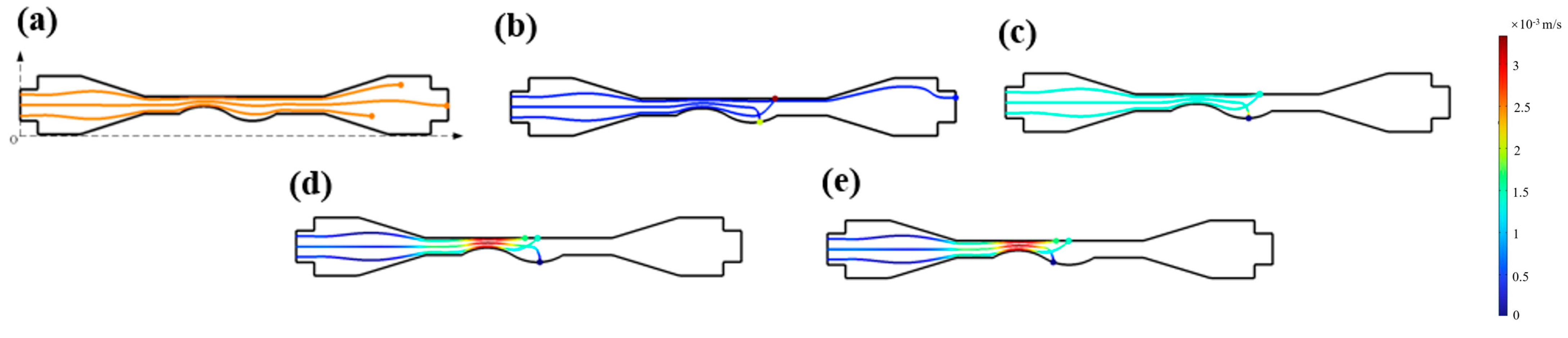
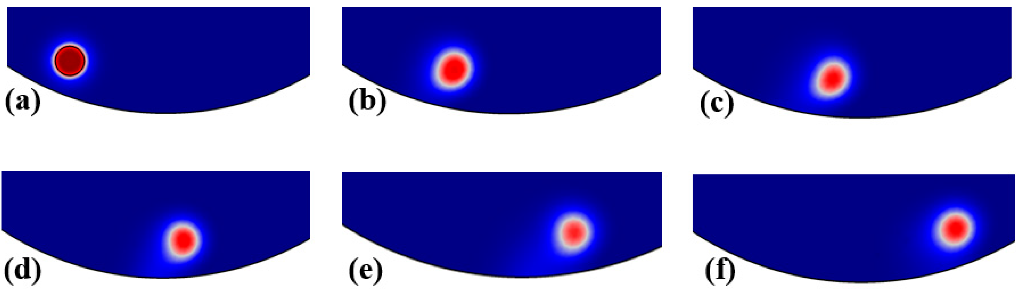
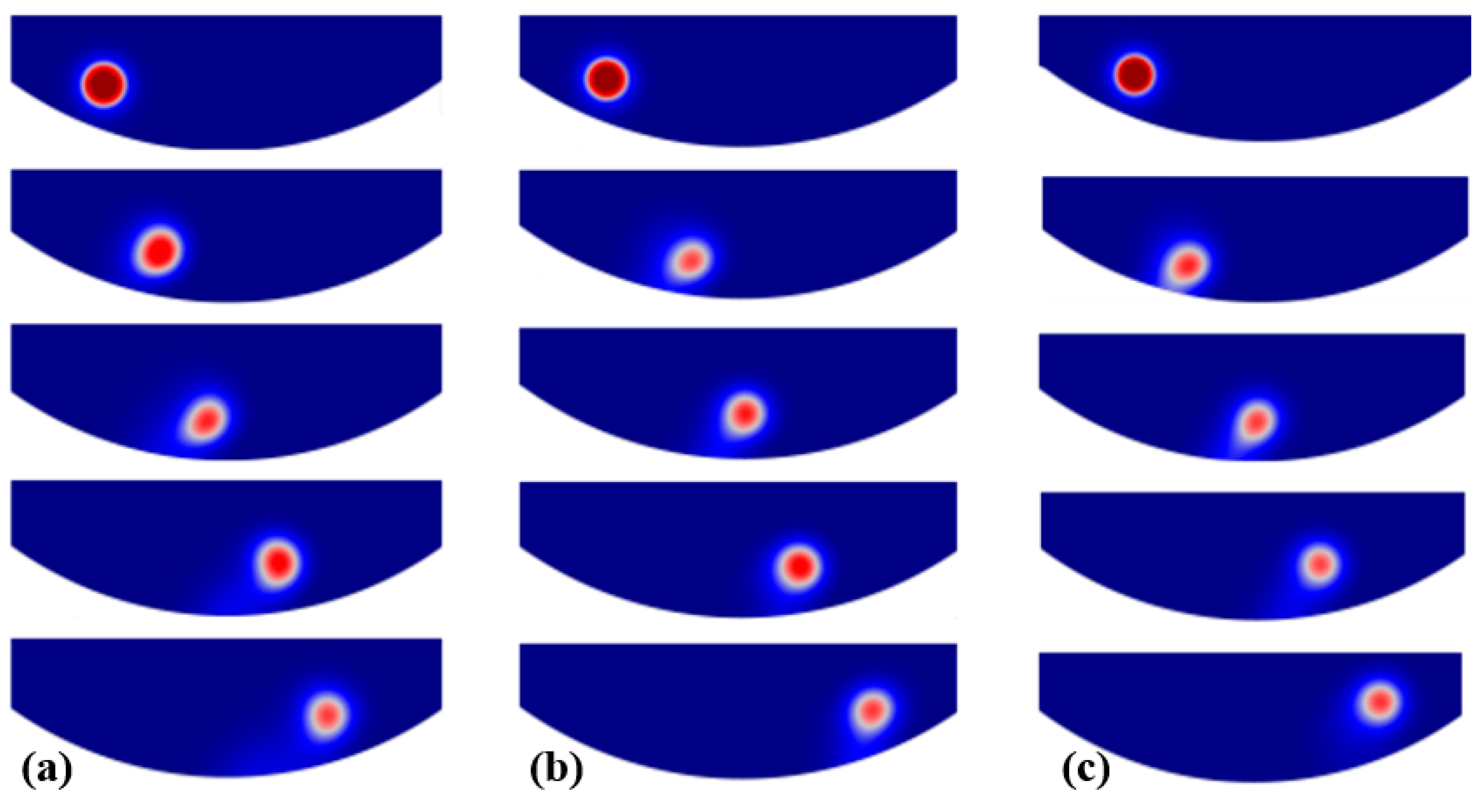
The physical models involved in the liquid metal-abrasive flow process were analyzed. An alternating electric field model, the SST turbulence model, and the Mixture model were selected as the physical field models. Simulations of the motion trajectories of liquid metal particles under the influence of alternating electric fields demonstrate the feasibility of using liquid metal particles as a driving medium for abrasives in polishing.
(2)
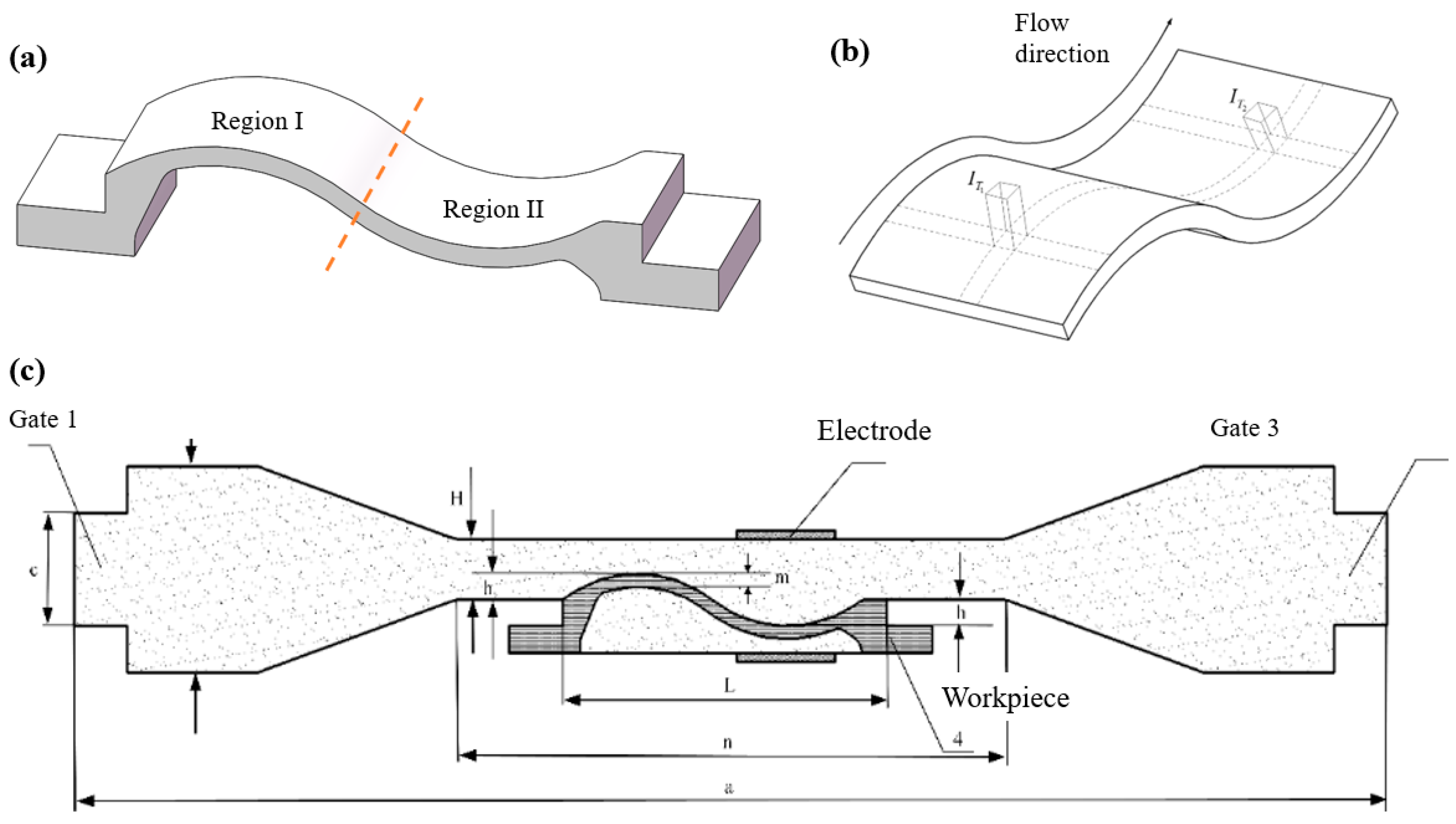
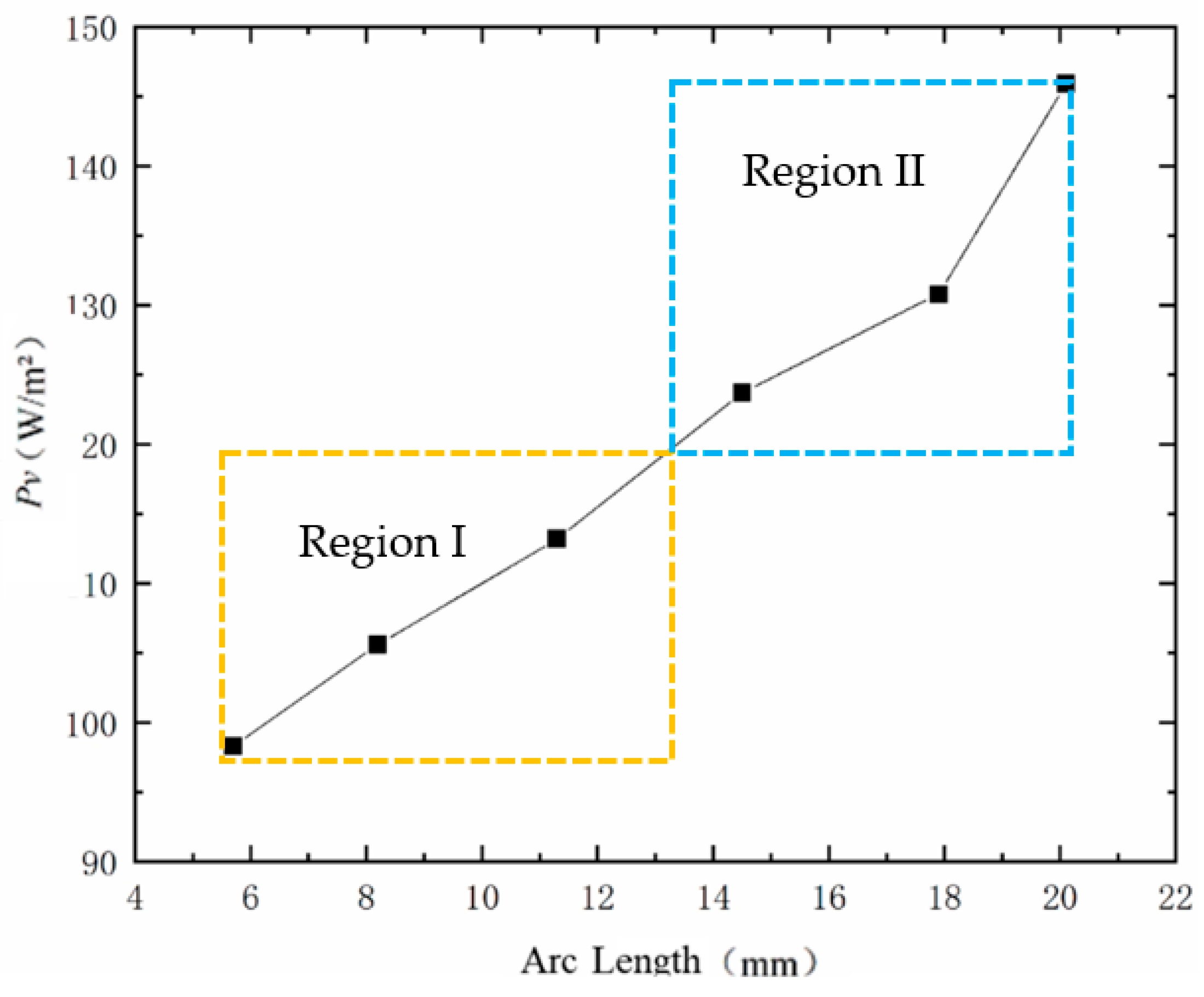
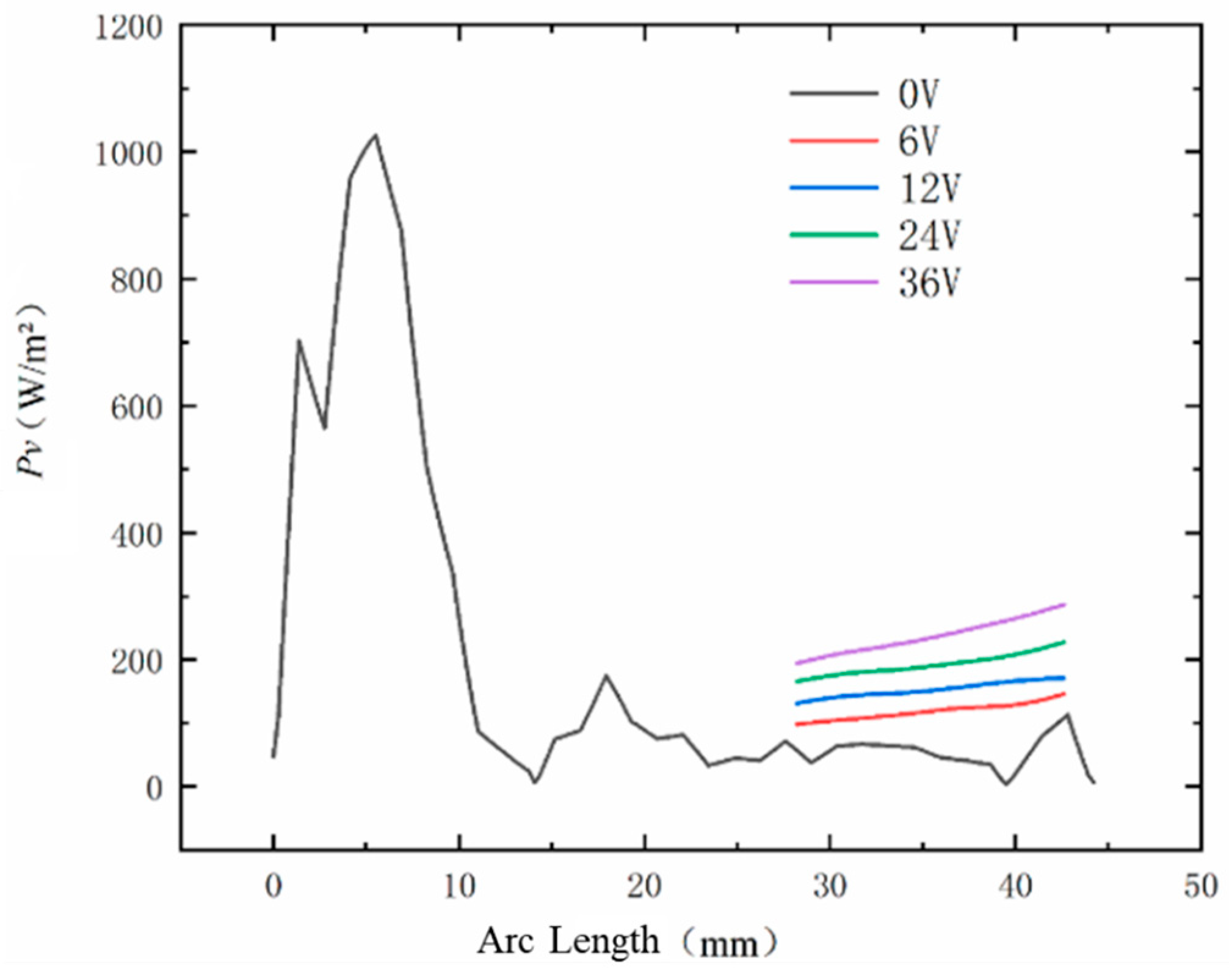
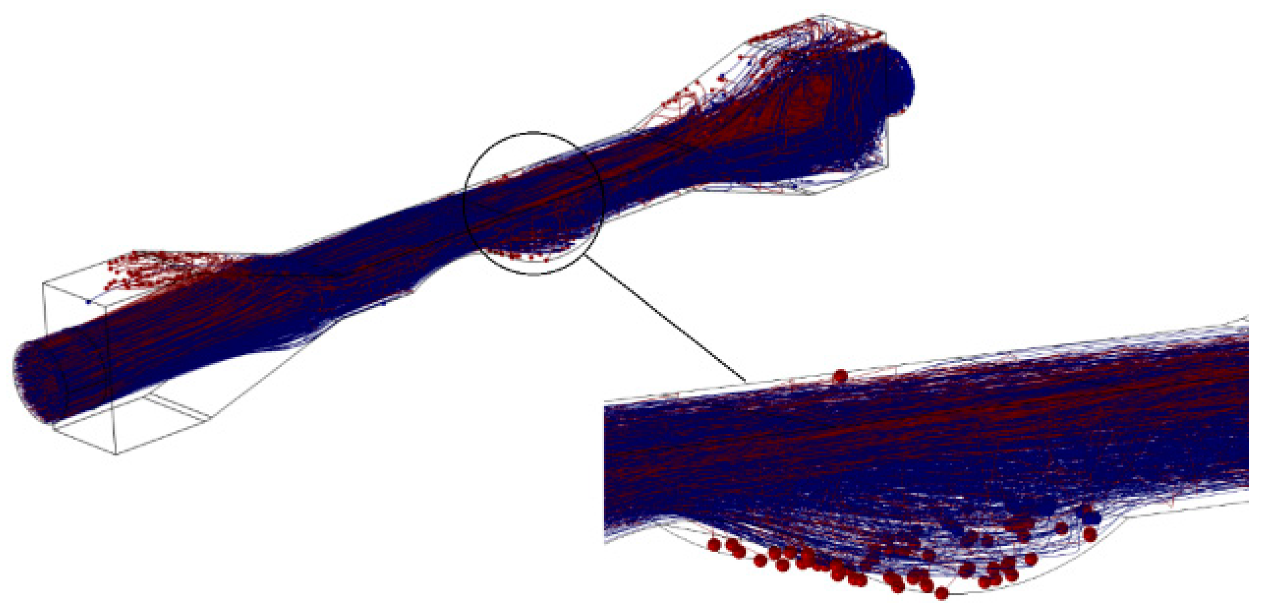
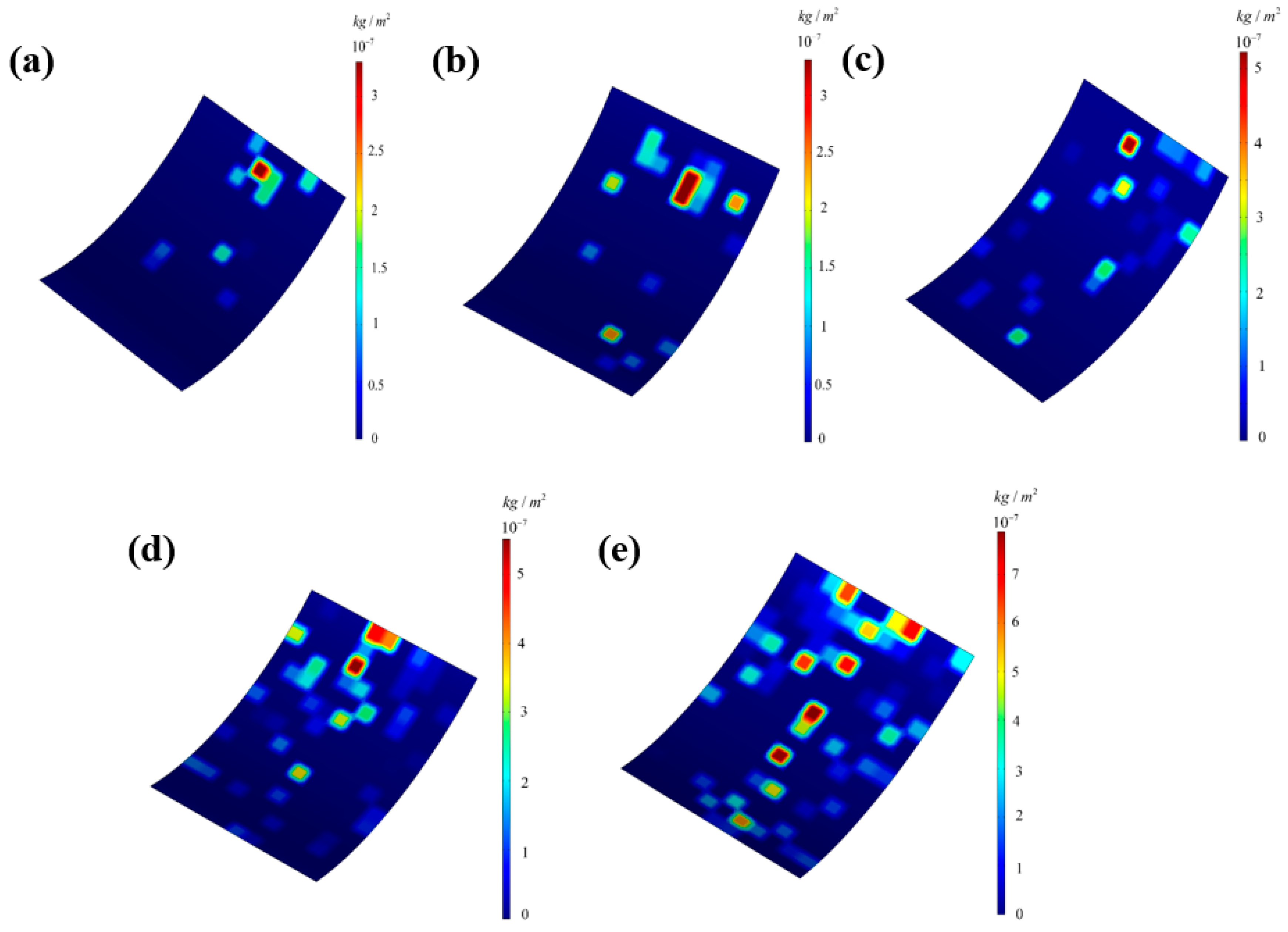
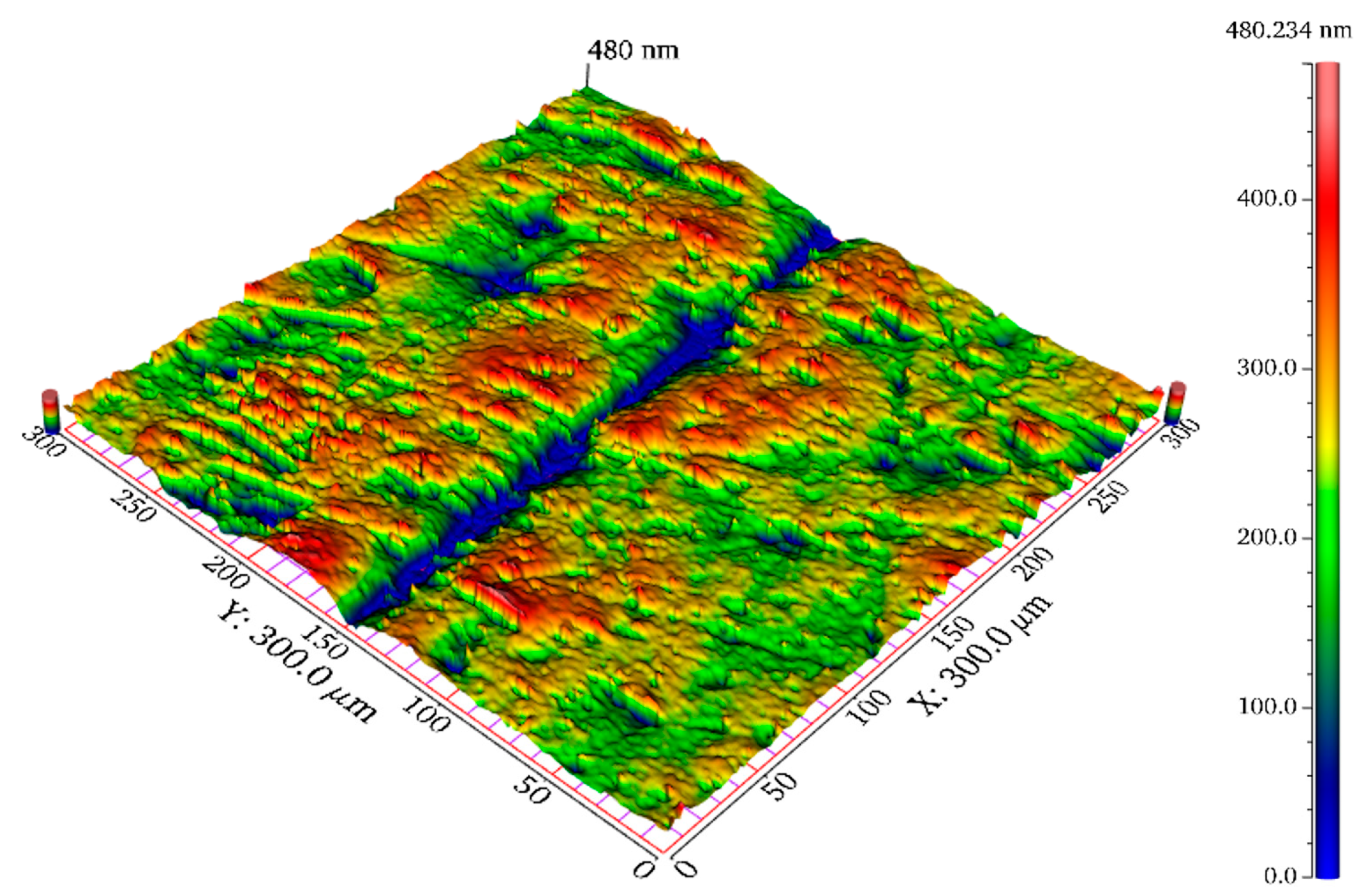
Through simulations of the liquid phase of liquid metal particles, the change in the Pv value of the workpiece surface as the particles move across the weak flow field areas of the curved workpiece under the electric field was examined. The results indicate that the Pv value of the workpiece surface continuously increases during the particle motion process, showing significant improvement compared to the original surface Pv value.
(3)
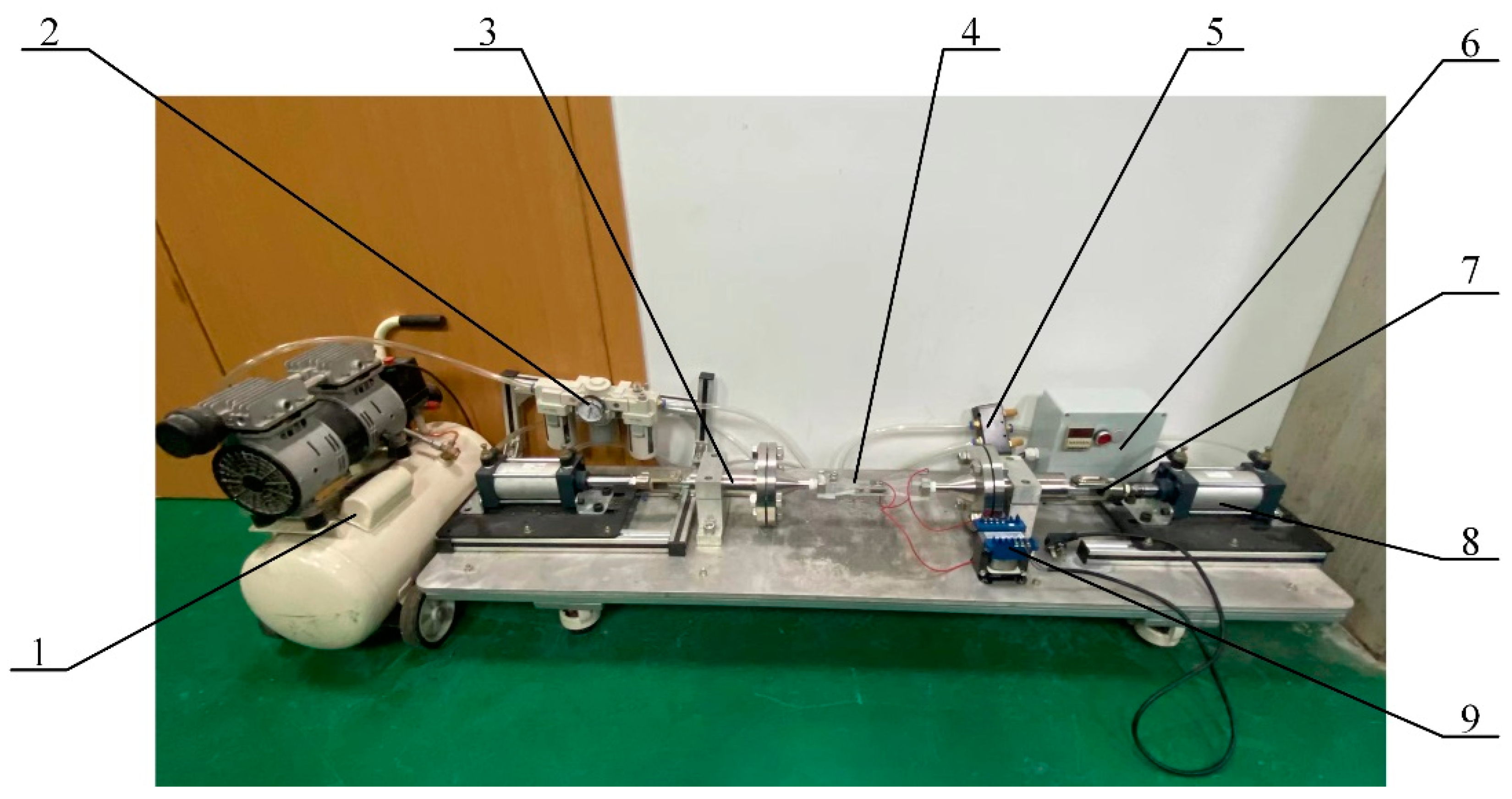
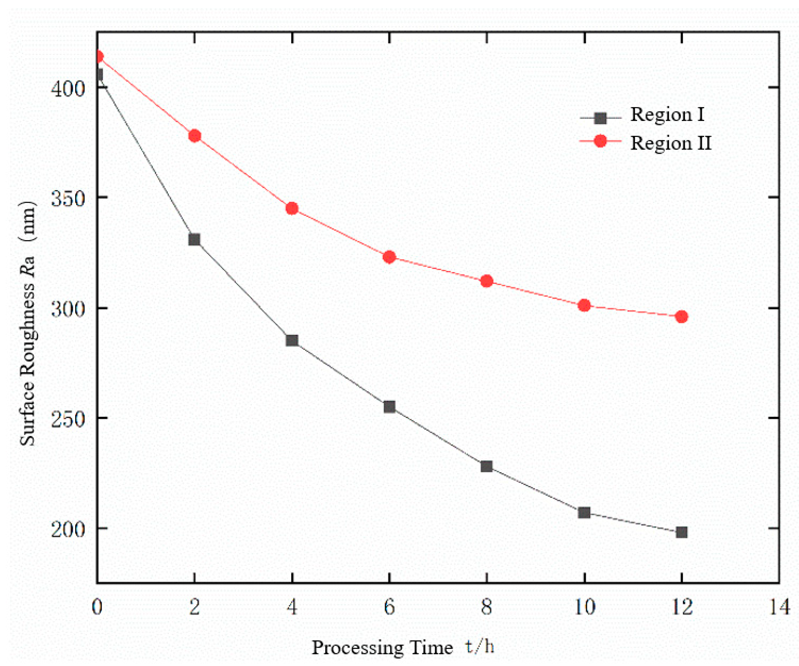
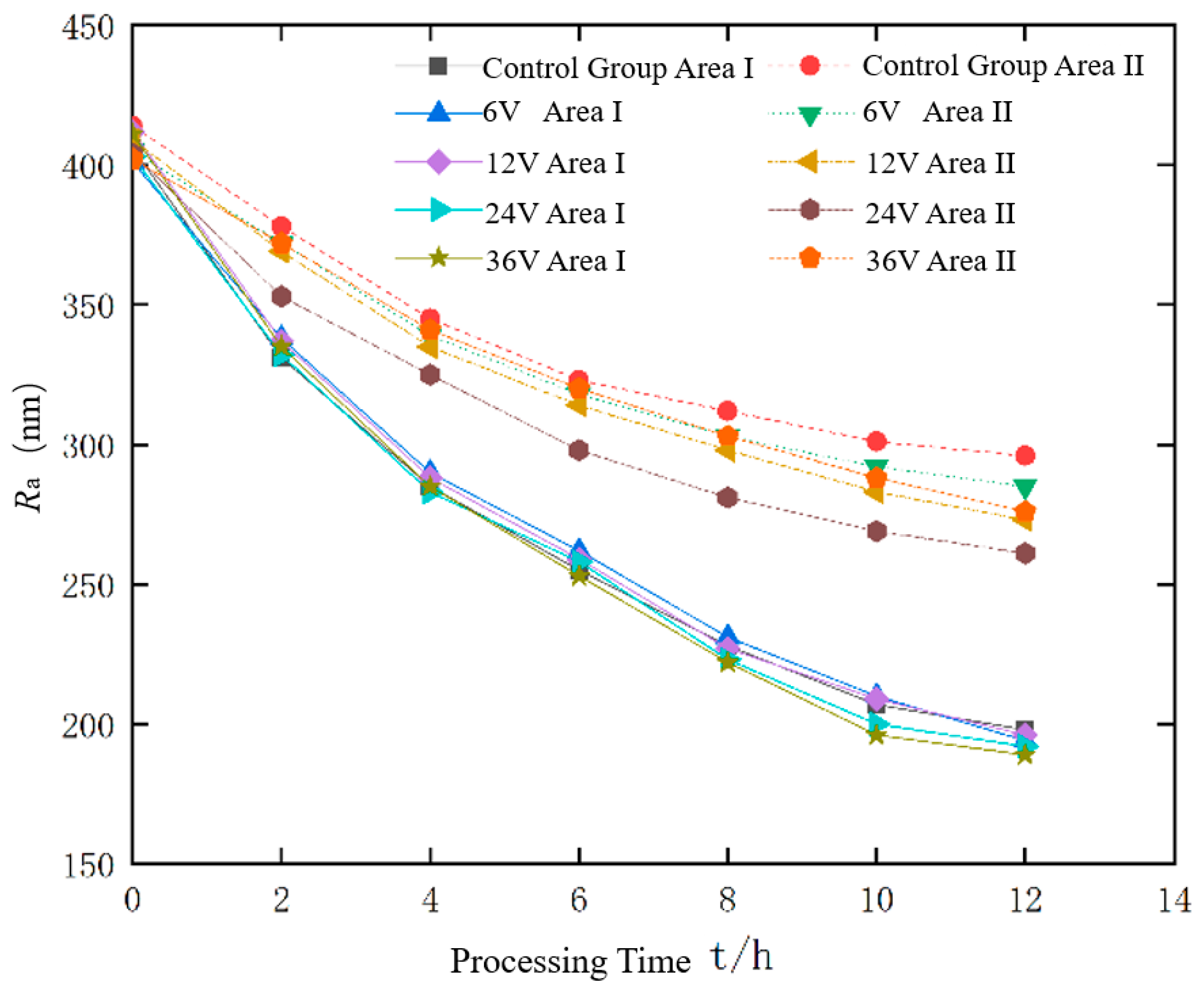
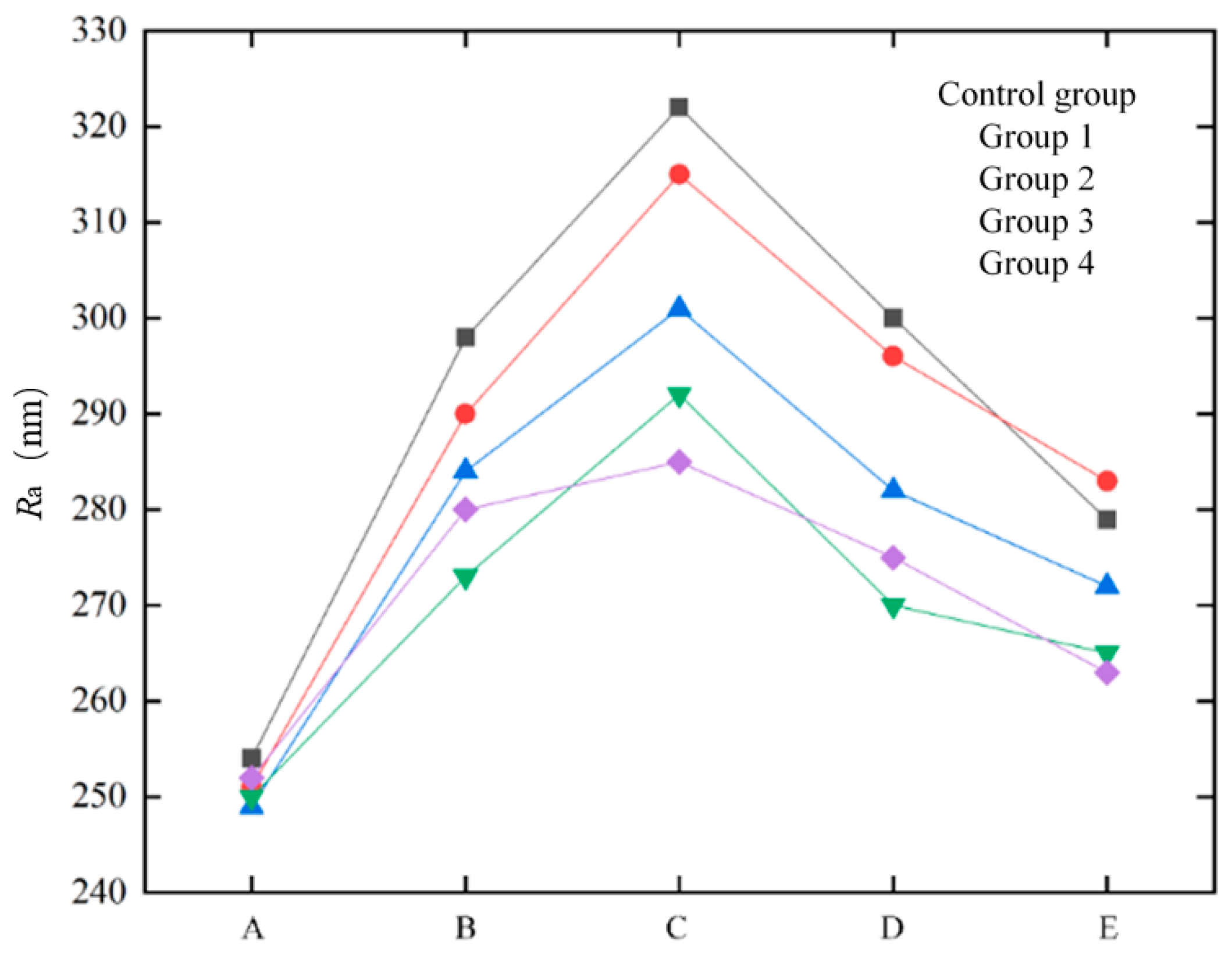
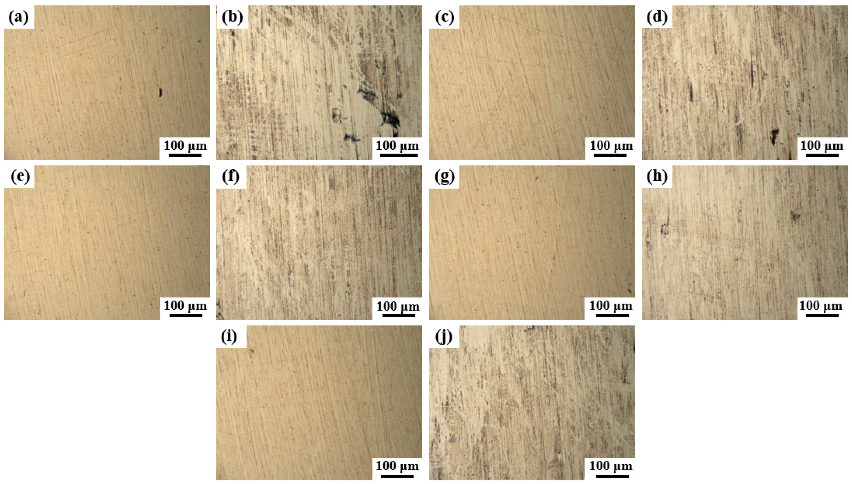
A comparative experiment was conducted between abrasive flow polishing (control group) and liquid metal-abrasive flow polishing under different alternating voltage conditions (experimental group), focusing on surface roughness and morphology. The results show that in the control group, surface roughness in the strong flow field is 100 nm lower than in the weak flow field, while in the experimental group, the roughness difference is reduced, with the 24 V alternating electric field achieving the smallest difference of 58 nm and a 44% improvement in polishing uniformity. This demonstrates that electrostatic field-controlled liquid metal-abrasive flow polishing enhances surface polishing uniformity on curved components.
(4)
The interaction of parameters such as flow rate, voltage, and abrasive concentration may lead to mismatches in the polishing process, complicating optimal parameter selection. To address these challenges, a synergistic optimization of the fluid and electric field, along with numerical simulations, is essential for improving experimental accuracy and reliability.

Author Contributions

Conceptualization, L.Z.; Review and editing, formal analysis and investigation, screening, retrieval, selection, and data collection, Y.F.; Formal analysis, R.W.; Funding acquisition, L.Z.; Investigation, Z.W.; Supervision, Z.W.; Writing—original draft, B.Z.; Writing—reviewing and editing, L.Z. and Y.F. All authors have read and agreed to the published version of the manuscript.

Funding

This research was funded by the National Natural Science Foundation of China (No. 52375467) and the Zhejiang Provincial Natural Science Foundation of China (No. LZ24E050009).

Data Availability Statement

Data available on request due to restrictions.

Conflicts of Interest

Author Rui Wang was employed by the Hangzhou Leban Intelligent Technology Co., Ltd. The remaining authors declare that the research was conducted in the absence of any commercial or financial relationships that could be construed as a potential conflict of interest.

References

  1. Genc, O.; Unal, R. Development of gamma titanium aluminide (γ-TiAl) alloys: A review. J. Alloys Compd. 2022, 929, 167262. [Google Scholar] [CrossRef]
  2. NIInomi, M.; Narushima, T.; Nakano, T. Recent Research and Development in the Processing, Microstructure, and Properties of Titanium and Its Alloy. Mater. Trans. 2024, 65, 1600–1611. [Google Scholar] [CrossRef]
  3. Xu, J.; Zhang, B.; Qu, W.; Sun, L. Advancements and Applications of Laser Surface Treatment on Titanium Alloys. Rare Met. Mater. Eng. 2024.
  4. Tetsui, T. Identifying low-cost, machinable, impact-resistant TiAl alloys suitable for last-stage turbine blades of jet engines. Intermetallics 2024, 168, 108263. [Google Scholar] [CrossRef]
  5. Tetsui, T.; Mizuta, K. Detrimental Effects of βo-Phase on Practical Properties of TiAl Alloys. Metals 2024, 14, 908. [Google Scholar] [CrossRef]
  6. Sun, H.; Zhang, L.; Wang, Y.; Qin, Y.; Xie, Z.; Lila, A.; Xu, N.; Huang, K.; Wang, J.; Huang, J. Improving fatigue life of a titanium alloy through coupled electromagnetic treatments. Int. J. Fatigue 2025, 191, 108676. [Google Scholar] [CrossRef]
  7. Zheng, G.A.; Xu, P.; Wang, T.; Yan, Q. Study on the bubble collapse characteristics and heat transfer mechanism of the microchannel reactor. Processes 2025, 13, 281. [Google Scholar] [CrossRef]
  8. Liu, J.; Zeng, X.; Zhang, P.; Peng, X.; Yu, D. Counterion-Driven Mechanochemical Reactions at TC4 Alloy/SiO2 Interfaces: Electrical Double Layer and Dynamic Ionic Radius. Tribol. Lett. 2025, 73, 1. [Google Scholar] [CrossRef]
  9. Zhang, Z.; Shi, Z.; Du, Y.; Yua, Z.; Guo, L.; Guo, D. A novel approach of chemical mechanical polishing for a titanium alloy using an environment-friendly slurry. Appl. Surf. Sci. 2018, 427, 409–415. [Google Scholar] [CrossRef]
  10. Deng, C.; Jiang, L.; Qian, L. Synergistic Effect of F−and Persulfate in Efficient Titanium Alloy Chemical Mechanical Polishing. ECS J. Solid State Sci. Technol. 2021, 10, 114003. [Google Scholar] [CrossRef]
  11. Jaritngam, P.; Tangwarodomnukun, V.; Qi, H.; Dumkum, C. Surface and subsurface characteristics of laser polished Ti6Al4V titanium alloy. Opt. Laser Technol. 2020, 126, 106102. [Google Scholar] [CrossRef]
  12. Li, P.; Liu, B.; Li, L.; Gong, Y.; Zhou, J.; Lu, J. Study on surface quality of ultrasonic assisted underwater laser polishing. J. Mater. Res. Technol. 2023, 27, 5761–5771. [Google Scholar] [CrossRef]
  13. Obeidi, M.A.; Mussatto, A.; Dogu, M.N.; Sreenilayam, S.P.; McCarthy, E.; Ahad, I.U.; Keaveney, S.; Brabazon, D. Laser surface polishing of Ti-6Al-4V parts manufactured by laser powder bed fusion. Surf. Coat. Technol. 2022, 434, 128179. [Google Scholar] [CrossRef]
  14. Fu, D.N.; Sheng, J.; Wang, L.J.; Zhang, X.J.; Yang, R.D.; Li, X.K.; Wang, Y. In situ silver-loaded cellulose for high-strength antibacterial composite air filtration paper. Cellulose 2025, in press. [Google Scholar]
  15. Wang, S.-F.; Wang, Y.; Wen, J.-C.; Suo, H.-L.; Liu, Z.-Z.; Suo, W.-h.; Zhao, C.-C. Study on electrochemical polishing of TC4 alloy. Mater. Res. Express 2021, 8, 106520. [Google Scholar] [CrossRef]
  16. Wang, Y.; Liu, H.; Yin, X.; Zhou, Y.; Feng, M.; Li, S. Study on electrochemical polishing mechanism of TC4 titanium alloy. Phys. Scr. 2024, 99, 085983. [Google Scholar] [CrossRef]
  17. Xu, W.X.; Xu, P.; Yang, Y.; Tan, D.P.; Li, L. The utilization and advancement of laser ultrasound testing in the assessment of aerospace composite characteristics: A review. Chin. J. Aeronaut. 2025, in press. [Google Scholar]
  18. Shen, M.; Wu, L.; Wei, M.; Chen, H.; Yuan, J.; Lyu, B.; Deng, H.; To, S.; Beri, T.H.; Hang, W. High-efficiency free-damage electrochemical shear-thickening polishing of single-crystal silicon carbide. J. Manuf. Process. 2024, 132, 532–543. [Google Scholar] [CrossRef]
  19. Dong, J.; Shi, J.; Ma, Z.; Yu, T. Research of the FLC + PID switching control strategy based on real-time error for the pneumatic polishing force regulating system. Eng. Sci. Technol. Int. J. 2024, 51, 101659. [Google Scholar] [CrossRef]
  20. Zhang, Y.K.; Li, Z.; Li, L.; Wang, C.Y.; Wu, J.F.; Xie, Y.S.; Yin, Z.C.; Tan, D.P. Deposition mechanism of microscopic impacting droplets on flexible porous substrates. Int. J. Mech. Sci. 2025, in press. [Google Scholar]
  21. Zhu, G.; Zeng, X.; Gao, Z.; Gong, Z.; Duangmu, W.; Zeng, Y.; Lu, C. Study on vibration stability of aircraft engine blades polished by robot controlled pneumatic grinding wheel. J. Manuf. Process. 2023, 99, 636–651. [Google Scholar] [CrossRef]
  22. Du, H.; Sun, Y.; Feng, D.; Xu, J. Automatic robotic polishing on titanium alloy parts with compliant force/position control. Proc. Inst. Mech. Eng. Part B J. Eng. Manuf. 2015, 229, 1180–1192. [Google Scholar] [CrossRef]
  23. Hung, J.-C.; Yang, P.-J.; Lin, X.-H.; Jian, S.-Y.; Kao, C.-H.; Ferng, Y.-C.; Huang, Y.-S.; Jen, K.-K. Surface passivation and brightening of titanium-based AM materials using a robotic electrochemical mechanical polishing system. Int. J. Adv. Manuf. Technol. 2024, 134, 4339–4352. [Google Scholar] [CrossRef]
  24. Zhang, H.; Chen, S.; Wang, H.; Qin, Y.; Song, Z. Surface Performance of Titanium Alloy Brake Shell Polished by Industrial Robot Based on Digital Twin. Int. J. Aerosp. Eng. 2024, 2024, 6130930. [Google Scholar] [CrossRef]
  25. Zeng, X.; Zhu, G.; Gao, Z.; Ji, R.; Ansari, J.; Lu, C. Surface polishing by industrial robots: A review. Int. J. Adv. Manuf. Technol. 2023, 125, 3981–4012. [Google Scholar] [CrossRef]
  26. Jaritngam, P.; Saetang, V.; Qi, H.; Dumkum, C. Surface polishing of additively manufactured Ti6Al4V titanium alloy by using a nanosecond pulse laser. Int. J. Adv. Manuf. Technol. 2023, 127, 3463–3480. [Google Scholar] [CrossRef]
  27. Tahir, A.F.M.; Aqida, S.N. An investigation of laser cutting quality of 22MnB5 ultra high strength steel using response surface methodology. Opt. Laser Technol. 2017, 92, 142–149. [Google Scholar] [CrossRef]
  28. Telegin, S.V.; Lyasnikova, A.V.; Dudareva, O.A.; Grishina, I.P.; Markelova, O.A.; Lyasnikov, V.N. Laser Modification of the Surface of Titanium: Technology, Properties and Prospects of Application. J. Surf. Investig. X-Ray Synchrotron Neutron Tech. 2019, 13, 228–231. [Google Scholar] [CrossRef]
  29. Wang, X.; Wang, Y.; Shao, X.; Zhou, K.; Deng, Q.; Yuan, Z.; Lyu, B. Electrochemical Polishing Method for Titanium Alloys with a Microgroove Structure. Processes 2024, 12, 1114. [Google Scholar] [CrossRef]
  30. Dai, Y.; Li, S.; Feng, M.; Chen, B.; Qiao, J. Fundamental Study of Phased Array Ultrasonic Cavitation Abrasive Flow Polishing Titanium Alloy Tubes. Materials 2024, 17, 5185. [Google Scholar] [CrossRef]
  31. Wang, J.; Dong, X.; Zhu, L.; Zhou, Z. Theoretical and Experimental Investigation on a Novel Cavitation-Assisted Abrasive Flow Polishing Method. Micromachines 2024, 15, 1142. [Google Scholar] [CrossRef] [PubMed]
  32. Ji, R.; Qi, Z.; Chen, J.; Zhang, L.; Lin, K.; Lu, S.; Li, Y. Numerical and Experimental Investigation on the Abrasive Flow Machining of Artificial Knee Joint Surface. Crystals 2023, 13, 430. [Google Scholar] [CrossRef]
  33. Choopani, Y.; Khajehzadeh, M.; Razfar, M.R. An experimental study on the abrasive flow machining of aluminum alloy (AA 2024). SN Appl. Sci. 2023, 5, 151. [Google Scholar] [CrossRef]
  34. Peta, K. Multiscale Wettability of Microtextured Irregular Surfaces. Materials 2024, 17, 5716. [Google Scholar] [CrossRef]
  35. Lin, Z.; Li, T.; Yang, S.; Ji, B.; Wang, Z. Revolutionizing flexible electronics with liquid metal innovations. Device 2024, 2, 100331. [Google Scholar] [CrossRef]
  36. Ma, Y.; Feng, B.; Li, K.; Zhang, L. Application of liquid metal driven-abrasive flow to material removal for the inner surface of channel. Powder Technol. 2025, 452, 120487. [Google Scholar] [CrossRef]
  37. Zhang, X.-D.; Liu, J. Perspective on liquid metal enabled space science and technology. Sci. China-Technol. Sci. 2020, 63, 1127–1140. [Google Scholar] [CrossRef]
  38. Li, Z.; Wang, C.Y.; Li, L.; Wu, J.F.; Yin, Z.C.; Tan, D.P. Numerical investigation of mesoscale multiphase mass transport mechanism in fibrous porous media. Eng. Appl. Comput. Fluid Mech. 2024, 18, 2363246. [Google Scholar] [CrossRef]
  39. Li, Y.; Chen, Q.; Zhang, L. Titanium Alloy Thin-walled Curved Surface Liquid Metal-abrasive Flow Machining Simulation and Experimental Research. J. Mech. Eng. 2021, 57, 220–231. [Google Scholar]
  40. Zheng, G.A.; Weng, X.X.; Wang, T.; Xu, P.; Xu, W.X.; Li, L.; Xu, X.F.; Tan, D.P. Piezoelectric ultrasonic coupling-based polishing of micro-tapered holes with abrasive flow. J. Zhejiang Univ. Sci. A 2025. [Google Scholar] [CrossRef]
  41. Zhang, L.; Zheng, B.; Xie, Y.; Ji, R.; Li, Y.; Mao, W. Control Mechanism of Particle Flow in the Weak Liquid Metal Flow Field on Non-Uniform Curvature Surface Based on Lippmann Model. Front. Mater. 2022, 9, 895263. [Google Scholar] [CrossRef]
  42. Fu, Y.; Gao, H.; Yan, Q.; Wang, X.; Wang, X. Rheological characterisation of abrasive media and finishing behaviours in abrasive flow machining. Int. J. Adv. Manuf. Technol. 2020, 107, 3569–3580. [Google Scholar] [CrossRef]
  43. Tan, Y.; Ni, Y.; Wu, J.; Li, L.; Tan, D. Machinability evolution of gas–liquid-solid three-phase rotary abrasive flow finishing. Int. J. Adv. Manuf. Technol. 2023, 131, 2145–2164. [Google Scholar] [CrossRef]
  44. Liu, M.; Wang, J.; He, H.; Yuan, J.; Lyu, B.; Chen, H.; Peng, G. Performance of flexible CeO2 composite abrasive in force rheological polishing of fused silica glass. J. Manuf. Process. 2024, 126, 175–184. [Google Scholar] [CrossRef]
  45. Liu, M.; Wang, J.; Liu, W.; Wu, H.; Yuan, J.; Lyu, B.; Peng, G.; Zhang, J. Force rheological polishing of polycrystalline magnesium aluminate spinel using agglomerated diamond abrasive. Ceram. Int. 2024, 50, 55275–55285. [Google Scholar] [CrossRef]
  46. Li, L.; Xu, P.; Li, Q.H.; Zheng, R.Y.; Xu, X.M.; Wu, J.F.; He, B.Y.; Bao, J.J.; Tan, D.P. A coupled LBM-LES-DEM particle flow modeling for microfluidic chip and ultrasonic-based particle aggregation control method. Appl. Math. Model. 2025, in press. [Google Scholar]
  47. Tan, Y.F.; Ni, Y.S.; Xu, W.X.; Xie, Y.S.; Li, L.; Tan, D.P. Key technologies and development trends of the soft abrasive flow finishing method. J. Zhejiang Univ. Sci. A 2023, 24, 1043–1064. [Google Scholar] [CrossRef]
  48. Li, L.; Xu, P.; Li, Q.H.; Yin, Z.C.; Zheng, R.Y.; Wu, J.F.; Bao, J.J.; Qi, H.; Tan, D.P. Multi-field coupling particle flow dynamic behaviors of the microreactor and ultrasonic control method. Powder Technol. 2025, in press. [Google Scholar] [CrossRef]
  49. Wang, C.Y.; Li, Z.; Xu, P.; Hou, Y.Q.; Tan, D.P.; Li, L. Collision modelling approach and transient response mechanism of ring-ribbed cylindric shells for underwater vehicles. Appl. Math. Model. 2025, 141, 115923. [Google Scholar] [CrossRef]
  50. Wu, J.F.; Xu, P.; Li, L.; Li, Z.; Qi, H.; Wang, C.Y.; Zhang, Y.K.; Xie, Y.S.; Tan, D.P. Multiphase dynamic interfaces and abrasive transport dynamics for abrasive flow machining in shear thickening transition states. Powder Technol. 2024, 446, 120150. [Google Scholar] [CrossRef]
  51. Xu, P.; Li, Q.H.; Wang, C.Y.; Li, L.; Tan, D.P.; Wu, H.P. Interlayer healing mechanism of multipath deposition 3D printing models and interlayer strength regulation method. J. Manuf. Process. 2025, in press. [Google Scholar]
  52. Guo, X.M.; Yang, M.Y.; Li, F.Q.; Zhu, Z.C.; Cui, B.L. Investigation on Cryogenic Cavitation Characteristics of an Inducer Considering Thermodynamic Effects. Energies 2024, 17, 3627. [Google Scholar] [CrossRef]
Figure 1. Movement mechanism of liquid metal under an electric field: (a) Electric double-layer stabilized liquid metal particles; (b) Liquid metal particles under the action of an electric field.
Processes 13 00416 g001
Figure 2. Principle of the liquid metal mixed abrasive flow polishing.
Processes 13 00416 g002
Figure 3. Collision process between metal droplets and abrasive particles on the workpiece surface.
Processes 13 00416 g003
Figure 4. Workpiece and processing model. (a) Workpiece; (b) flow direction; (c) the multifield machining model; 1. the inlet of the flow channel; 2. the processing electrode of the flow channel; 3. the outlet of the flow channel; and 4. the curved titanium alloy workpiece.
Processes 13 00416 g004
Figure 5. Meshing of the multifield abrasive flow model.
Processes 13 00416 g005
Figure 6. Skewness of the grid. (a) Viewpoint 1; (b) viewpoint 2.
Processes 13 00416 g006
Figure 7. The abrasive flow process. (a) t = 0 s; (b) t = 0.01 s; (c) t = 0.02 s; (d) t = 0.03 s; (e) t = 0.05 s; (f) t = 0.13 s.
Processes 13 00416 g007
Figure 8. The motion trajectories of metal droplets. (a) No applied electric field; (b) 6 V alternating electric field; (c) 12 V alternating electric field; (d) 24 V alternating electric field; (e) 36 V alternating electric field.
Processes 13 00416 g008
Figure 9. Flow field velocity distribution. (a) Gate 1 is the entrance; (b) gate 3 is the entrance.
Processes 13 00416 g009
Figure 10. Motion diagram of liquid metal particles in liquid phase. (a) moment 1; (b) moment 2; (c) moment 3; (d) moment 4; (e) moment 5; (f) moment 6.
Processes 13 00416 g010
Figure 11. Pv change diagram of particle motion.
Processes 13 00416 g011
Figure 12. Motion diagram of liquid metal at different voltages. (a) 12 V; (b) 24 V; (c) 36 V.
Processes 13 00416 g012
Figure 13. Summary of Pv curves.
Processes 13 00416 g013
Figure 14. Simulation diagram of particle group motion.
Processes 13 00416 g014
Figure 15. Surface quality loss diagram of the workpiece under different AC voltages. (a) 0 V; (b) 6 V; (c) 12 V; (d) 24 V; (e) 36 V.
Processes 13 00416 g015
Figure 16. Processing experiment platform. 1. Air pump; 2. air source processor; 3. push rod cavity; 4. transparent resin flow channel; 5. electromagnetic reversing valve; 6. controller; 7. y connector; 8. cylinder; 9. transformer.
Processes 13 00416 g016
Figure 17. The 2D microscopic morphology before and after rough polishing. (a) The surface appearance before polishing; (b) the surface appearance after polishing.
Processes 13 00416 g017
Figure 18. Changes of surface roughness over time during abrasive flow machining.
Processes 13 00416 g018
Figure 19. Roughness changes of liquid metal-abrasive flow machining under different AC voltages.
Processes 13 00416 g019
Figure 20. Region II roughness measurement points.
Processes 13 00416 g020
Figure 21. Internal roughness distribution of Region II.
Processes 13 00416 g021
Figure 22. Three-dimensional topography of the surface before processing.
Processes 13 00416 g022
Figure 23. Surface morphology of each region in different experimental groups: (a) region Ⅰ under 0 V; (b) region II under 0 V; (c) region Ⅰ under 6 V; (d) region II under 6 V; (e) region Ⅰ under 12 V; (f) region II under 12 V; (g) region Ⅰ under 24 V; (h) region II under 24 V; (i) region Ⅰ under 36 V; (j) region II under 36 V.
Processes 13 00416 g023
Figure 24. Three-dimensional topography of each area in different experimental groups: (a) region Ⅰ under 0 V; (b) region II under 0 V; (c) region Ⅰ under 6 V; (d) region II under 6 V; (e) region Ⅰ under 12 V; (f) region II under 12 V; (g) region Ⅰ under 24 V; (h) region II under 24 V; (i) region Ⅰ under 36 V; (j) region II under 36 V.
Processes 13 00416 g024
Table 1. Geometric parameters of a physical model.
Geometrical ParameterabcnLHhm
size (mm)1852416764652.51.2
Table 2. Basic simulation parameters.
Simulation ParametersParameter Value
Curved workpiece materialTi-2Al-1.5Mn titanium alloy
Fluid density, ρ 1 / k g m 3 1000
Fluid conductivity, S / m 9.7
Abrasive density, ρ 2 / k g m 3 3200
Average diameter of abrasive particles, d / μ m 50
Abrasive particle volume fraction, V 1 /%10
Liquid metal particle volume fraction, V 2 /%5
Liquid metal particle density, ρ 3 / k g m 3 6400
Liquid metal particle density, V 2 /V6, 12, 24, 36 V AC, 50 Hz
Average diameter of liquid metal particles, D/mm1
Fluid inflow conditionsNormal inflow 4 m/s
Fluid outlet conditionsp = 0, inhibit backflow
Table 3. The process parameter comparison table.
Process ParameterLiquid Metal-Abrasive Flow ParameterAbrasive Flow Parameter
Abrasive typeSilicon carbideSilicon carbide.0
Liquid phase1 mol/L NaOH aqueous solution1 mol/L NaOH aqueous solution
Abrasive mesh size800 mesh800 mesh
Abrasive volume fraction (%)1010
Liquid metal volume fraction (%)55
AC voltage (V)6 V, 12 V, 24 V, 36 V0 V
Processing time (h)10 h10 h
Table 4. Initial surface roughness of workpiece.
GroupSa (nm)
Region IRegion II
Group 1401405
Group 2412409
Group 3403404
Group 4411402
Disclaimer/Publisher’s Note: The statements, opinions and data contained in all publications are solely those of the individual author(s) and contributor(s) and not of MDPI and/or the editor(s). MDPI and/or the editor(s) disclaim responsibility for any injury to people or property resulting from any ideas, methods, instructions or products referred to in the content.

