Article

Technical and Economic Analysis of a Novel Integrated Energy System with Waste Tire Pyrolysis and Biogas

1
State Grid Economic and Technological Research Institute Co., Ltd., Beijing 102209, China
2
School of Energy, Power and Mechanical Engineering, North China Electric Power University, Beijing 102206, China
*
Author to whom correspondence should be addressed.
Processes 2025, 13(2), 415; https://doi.org/10.3390/pr13020415
Submission received: 6 December 2024 / Revised: 10 January 2025 / Accepted: 18 January 2025 / Published: 5 February 2025

Abstract

:
To reduce dependence on fossil fuels, cope with the growing energy demand, and reduce greenhouse gas emissions, this paper innovatively designs a novel integrated energy system integrating anaerobic digestion of animal manure, fuel cell technology, gas turbine, and tire pyrolysis. The system maximizes the energy potential of biogas while synergistically treating waste tires, improving waste management’s flexibility, efficiency, and economic viability through multiple outputs such as electricity and by-products, subsystem synergies, equipment sharing, and economies of scale. Thermodynamic performance and economic feasibility are analyzed using Aspen Plus V14 simulation modeling, ensuring the system’s technical and economic viability. In this study, the simulation model of the system is established, and the techno-economic benefits of the system are analyzed. The simulation results show that the net electric power output of the system is 444.79 kW. Combined with the contribution of pyrolysis products, the system’s total efficiency reaches 70.88%. In only 4.79 years, the initial investment can be recovered, and in its 25-year service life, the system has realized a profit of 2,939,130 USD. The system realizes the energy and quality matching between different thermal processes through indirect collaborative treatment of different solid wastes, improves the conversion efficiency of biogas energy, co-treats waste tires, and reduces environmental pollution.

1. Introduction

The rapid development of China’s economy has led to a significant increase in solid waste, drawing growing attention from the government to the environmental issue of “waste encircling cities”. Standard waste management methods include source reduction, reuse, landfill disposal, and waste-to-energy conversion [1]. Among these, waste-to-energy enables the resourceful utilization of waste and reduces reliance on fossil fuels, making it a focal point of interest. Three primary ways to improve this process are to enhance working fluid parameters, minimize heat loss from exhaust steam, and integrate other thermal processes. Integrating other thermal processes involves complementing solid waste with other energy sources and achieving energy-quality matching across various thermal systems. This approach maximizes solid waste’s energy potential while improving waste management’s flexibility, efficiency, and economic viability through diverse outputs such as electricity, heat, by-products, subsystem synergies, equipment sharing, and economies of scale.
To reduce dependence on fossil fuels, cope with the growing energy demand, and reduce greenhouse gas emissions, research scholars have begun to pay attention to renewable energy sources. Among them, solar and wind energy have obvious shortcomings such as regional limitations, dependence on weather, and unpredictability of power supply. Therefore, many researchers advocate promoting biogas generated from biomass through anaerobic digestion (AD). It has many uses, such as heating and power generation, being used as automobile fuel, and being mixed into a natural gas supply network. Among them, the main ways of power generation are fuel cells, gas turbines, and internal combustion engines [2]. By adopting the above method, on the one hand, the waste will not be discharged into the environment, and the harmless treatment is realized; on the other hand, biogas as fuel realizes resource utilization.
Solid oxide fuel cells (SOFCs) have attracted much attention since their invention. As an electrochemical device, SOFCs have the ability to directly convert chemical energy into power. They are universal to all kinds of components and impurities in gas, which makes the equipment superior in performance. And the heat energy and chemical energy generated after the fuel reaction can be recycled by other thermal processes, thus improving conversion efficiency. Many studies have explored different methods of combining biogas with fuel cells. Soleimanpour et al. [3] proposed a cogeneration cycle based on solid oxide fuel cells and found that dry-reforming deposits less carbon because of higher operating temperatures. Ran et al. [4] designed a novel biogas-fueled SOFC hybrid system assisted with solar energy to help improve thermodynamic performance and reduce emissions. Illathukandy et al. [5] investigated the influence of hydrogen chloride traces in biogas on direct internal reforming in SOFCs to find out the safe operation conditions when biogas is employed as a fuel. Ishaq et al. [6] proposed a novel design to treat the organic fraction of municipal solid waste to generate electricity using SOFCs, with a minimum payback period of 5 years when considering an electricity price of 130 USD/MWh. Although the above studies have explored the combination of biogas and fuel cells to some extent, they all used biogas as a single fuel without considering the possibility of synergistic treatment with other fuels. The products are relatively single, which would be expected further to exploit the potential of biogas conversion into energy if the diversity of products can be fully utilized.
In 2017, the USA produced about 4 million tons of discarded tires, with only 18% used, resulting in the accumulation of tires in the American inventory. Rubber components are water-resistant and wear-resistant, which will degrade slowly for centuries, leading to serious environmental degradation. The organic content of waste tires is over 90%, which is a valuable biomass fuel. Although incineration and power generation can make use of tires as resources, they also release a lot of harmful gases such as volatile organic compounds and dioxins, causing serious environmental problems. In contrast, pyrolysis technology is classified as an advanced energy recovery technology, which helps to convert waste tires into fuel, and the products can be used for refining and establishing a new process cycle. Zhou et al. [7] analyzed the influence of low-temperature pyrolysis pretreatment on the co-combustion performance of coal and waste polyvinyl chloride/tire and found that the activation energy of coal is greatly decreased after the addition of waste polyvinyl chloride/tire. Lv et al. [8] proposed fast co-pyrolysis of Naomaohu coal with waste tires under negative pressure, and found that co-pyrolysis under negative pressure could inhibit the molten state of waste tires and decrease the secondary reaction of the volatiles. In these studies, the treatment of tires is at the level of co-combustion or co-pyrolysis. It does not consider the separate reactions of different raw materials through the deep coupling of different thermodynamic processes to improve the system’s efficiency.
To reduce reliance on fossil fuels while addressing the critical environmental challenge of “waste encirclement” faced by China, this study proposes an innovative polygeneration system that integrates fuel cells, gas turbines, tire pyrolysis, and waste heat recovery subsystems to enhance power output and co-process tires. In this novel system, purified biogas produced through anaerobic digestion and air is first compressed and preheated, then directed to the SOFC for electricity generation. Some of the exhaust gas from the anode is recirculated to increase hydrogen content and boost power output. The remaining stream is incinerated in the combustion chamber together with the cathode exhaust and tire pyrolysis gas. The flue gas enters the gas turbine (GT), generating electricity. The flue gas undergoes waste heat recovery processes, including preheating fuel and oxidant and supplying heat to the pyrolysis subsystem. The new system design produces valuable pyrolysis by-products and significantly enhances power output. The entire process efficiently, safely, cleanly, and economically harnesses biogas while co-processing tires. Thermodynamic performance and economic feasibility are analyzed using Aspen Plus V14 simulation modeling, ensuring the system’s technical and economic viability. The contribution of this paper is as follows:
(1)
The system developed in this paper can produce pyrolytic oil, pyrolytic carbon, and electricity at the same time. According to the characteristics of raw materials, animal manure, and waste tires are digested and pyrolyzed, respectively, to realize the indirect synergistic treatment of different solid wastes.
(2)
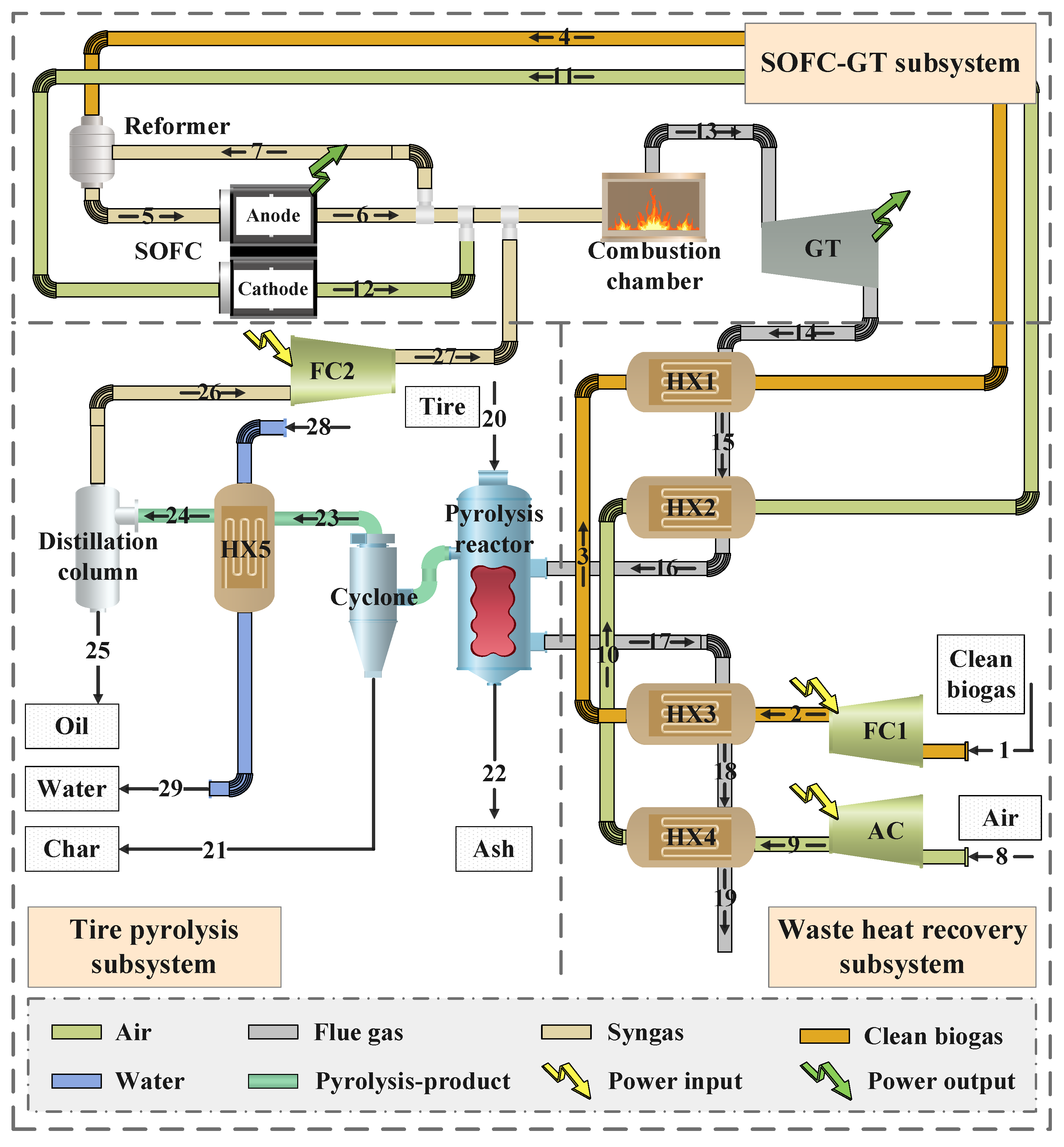
Biogas is first sent to SOFC-GT for power generation with hot exhaust gas used to preheat biogas and air and provide energy for the tire pyrolysis subsystem. The system can produce rich pyrolysis products and improve the power output. The complementary subsystems, equipment sharing, and scale effect bring certain benefits, which greatly improve the utilization efficiency of biogas and provide rich economic returns.
(3)
The system maximizes the energy potential of biogas while synergistically treating waste tires, improving waste management’s flexibility, efficiency, and economic viability through multiple outputs such as electricity and by-products, subsystem synergies, equipment sharing, and economies of scale. It helps to reduce dependence on fossil fuels while addressing the serious environmental challenge of “garbage surrounding the city” that China is facing.
In this study, each subsystem is first modeled and validated by Aspen Plus V14 to ensure the reliability of the results. Then, the parameters are input into the integrated energy system. For the simulation results of the whole system, the technical and economic feasibility of the novel integrated energy system is analyzed in terms of energy, exergy, and economy, respectively.

2. System Structure and Theoretical Methods

As shown in Figure 1, the clean biogas produced by anaerobic digestion is firstly compressed and preheated, then sent to the anode of the SOFC to generate electricity. At the same time, the air is delivered to the cathode. Some of the exhaust gas from the anode is recirculated to increase the hydrogen content. In contrast, the other gas is mixed with the cathode exhaust gas in a combustion chamber and burned with pyrolysis gas from tire pyrolysis. After complete combustion, the flue gas enters the gas turbine for power output. Then, it undergoes a series of waste heat utilization processes, including preheating the biogas and air to provide heat for the pyrolysis subsystem. The tire pyrolysis subsystem is selected to operate at 400 °C to convert waste tires into carbon black, pyrolysis gas, and pyrolysis oil to match the system. Specifically, the pyrolysis reactor outlet products enter a cyclone separator, where the carbon black is separated from the bottom, and the volatiles pass sequentially through a heat exchanger and a distillation column, where they are separated. The gas, called pyrolysis gas, is pressurized in the fuel compressor and sent to the combustion chamber for incineration to provide power for the gas turbine to perform the work. The liquid phase, known as pyrolysis oil, is sold to improve the economics of the system. The whole system is efficient, safe, clean, and economical, and it gradually develops and utilizes biogas and resource utilization of waste tires, which achieves high energy efficiency and can be a feasible solution for waste management.

2.1. System Structure

The proposed system is simulated using the commercial software Aspen Plus V14, operated by Aspen Technology, Inc., located in Bedford, MA, USA. It is highly respected for its rigorous thermodynamic analysis procedures and physical property database. Figure 2 shows the simulation model of the system, which is divided into three pieces: the SOFC-GT, tire pyrolysis, and waste heat recovery subsystems. Since there are no specialized SOFC and pyrolysis models in Aspen Plus V14, there is a need to develop accurate models of these two processes.
Some basic modeling assumptions are used to simplify the modeling and analysis.
(a)
The system maintains a thermodynamic equilibrium condition;
(b)
The modules are zero-dimensional and maintain a uniform temperature;
(c)
The ambient temperature and pressure are always 25.0 °C and 101.325 kPa;
(d)
Air comprises of 21% O2 and 79% N2;
(e)
Changes in kinetic and potential energy are neglected;
(f)
Heat loss, mass loss, and pressure drop are neglected.

2.2. Theoretical Methods

2.2.1. Solid Oxide Fuel Cells

When modeling SOFCs, Aspen Plus V14 cannot fully account for ionic crossings and electron migration in the reaction. Therefore, “Fortran” programming languages and “Design-spec” functions must be imported to help build a complete SOFC model, and the calculation hierarchy of the model is shown in Figure 3. The simulation model of SOFCs is shown in Figure 4.
Specifically, the clean biogas is combined with circulating anode gas. The resulting mixture enters a pre-reformer, with the required steam/carbon (S/C) ratio determining the quantity of circulating gas. Considering internal reforming could form carbon and a large temperature gradient due to the endothermic nature, an adiabatic pre-reformer is included in the SOFC to convert the high hydrocarbons and a small amount of methane in the gas mixture to reduce the fuel gas temperature. The pre-reformer is used to reduce the temperature of the fuel gases. The pre-reformer is used to reduce the temperature of the fuel gases. The reactions occurring in the pre-reformer are shown in the following equations.
C n H 2 n + 2 + n H 2 O ( 2 n + 1 ) H 2 + n C O 2
C O + H 2 O C O 2 + H 2
A “Heater” module (named “COOLER”) is chosen to simulate the temperature drop due to the reaction’s need for heat. It is worth noting that “Design-spec” estimates the operating temperature of the reformer so that the net heat load (Q2) before the reformer is equal to zero.
Although CO and CH4 in pre-converted fuels can be oxidized directly without a catalyst in SOFC at 1000 °C, it is not as favorable as the water–gas shift reaction. Assuming that only H2 (the more easily oxidized fuel) reacts electrochemically is standard practice in systems analysis. Transferring CO and CH4 to H2 and then reacting it both simplifies the analysis and accurately predicts the electrochemical behavior of the SOFC. Equations (3)–(5) are considered in the SOFC cell stack. In the system simulation, only part of the air flows into the “RGibbs” module to indicate the migration of oxygen ions. This process uses Equations (6)–(8) to calculate the quantity of required oxygen ( n O 2 , required ) to achieve the target values for the fuel utilization factor ( U f ) and the fuel equivalent hydrogen molar flow rate ( n H 2 , equivalent ).
H 2 + 0.5 O 2 H 2 O
CH 4 + H 2 O C O + 3 H 2
C O + H 2 O C O 2 + H 2
n O 2 , required = 0.5 × U f × n H 2 , equivalent
U f = n H 2 , consumed / n H 2 , equivalent
n H 2 , equivalent = n H 2 + n C O + 4 × n C H 4 + 7 × n C 2 H 6 + 10 × n C 3 H 8
where n H 2 , n C O , n C H 4 , n C 2 H 6 , and n C 3 H 8 are the molar flow rates of hydrogen, carbon monoxide, methane, ethane, and propane in the fuel (mol/s), respectively.
Assuming that the electrochemical reaction takes place at “ANODE”, the heat released by the process is then sent to the anode to heat the air via the heat flow Q3. The heat flow (Q3) is calculated by the “Design-spec” calculator to keep the cathode and anode outlet temperatures equal. The additional airflow absorbs the heat of the battery pack and stabilizes the cell temperature at 910 °C. Therefore, with a heat loss of 2%, the required air mass flow rate can be calculated and satisfies the following equation.
Q 4 V × I ( 0.02 × Q 4 ) = 0
where Q 4 is the net heat load of the “ANODE” module.
The SOFC current ( I , A) and current density ( i c , mA/cm2) can be estimated sequentially by the following equations [9].
I = ( n H 2 + n C O + n C H 4 + 7 × n C 2 H 6 + 10 × n C 3 H 8 ) × 2 × F × U f
i c = n H 2 × N e × F N A
where F is Faraday’s constant (C/mol), here take 96,485 C/mol; N e and N are the number of electrons converted in the process and all electrons, respectively; and A is the active surface area of a cell (cm2).
The SOFC actual voltage ( V SOFC , mV) is calculated based on a reference operating condition using the following formula [10].
V SOFC = V ref + Δ V p + Δ V T + Δ V anode + Δ V cathode
V ref = 0.72988 + 2.00014 × 10 4 × i c 9.668 × 10 7 × i c 2 + 2.626 × 10 10 × i c 3
Δ V p = 76 × log p SOFC / p ref
Δ V T = 0.008 × T SOFC T ref × i c
Δ V anode = 172 × log p H 2 / p H 2 O p H 2 / p H 2 O ref
Δ V cathode = 92 × log p O 2 p O 2 ref
where V ref is the reference voltage (mV) [10]; Δ V P , Δ V T , Δ V anode , and Δ V cathode are the effects of fuel cell operating pressure, operating temperature, fuel composition, and oxidant composition on the actual voltage (mV), respectively; p SOFC and T SOFC are the actual operating pressure (kPa) and the temperature (K), respectively; p ref is the reference pressure of the system (100 kPa); T ref is the reference temperature (1273.15 K); p H 2 / p H 2 O and ( p H 2 / p H 2 O ) ref are the actual and the reference hydrogen and steam (0.15 kPa), respectively; p O 2 is the average partial pressure of oxygen in the cathode (16.4 kPa); and ( p O 2 ) ref is the reference average partial pressure of oxygen in the cathode (here 16.4 kPa).

2.2.2. Tire Pyrolysis

Another challenge in the modeling process is the pyrolysis system. Reference [11] developed a kinetic model to improve the model’s accuracy and determined the parameters for each reaction. As shown in Figure 2, the pyrolysis reaction consists of the “RYield” (named “DECOMPOS”) and the “RPlug” (named “KINETIC”) modules. The tire, considered non-conventional, is converted into conventional elemental components in “DECOMPOS”, with the specific yield determined by the “Fortran” calculator. In the plug-flow reactor, pyrolysis reactions are simulated using reaction equations and parameters from reference [11]. The hot flue gas from the No. 2 heat exchanger heats the pyrolysis reactor. The non-vapor components of the pyrolysis product are in the “Flash2” module (named “VESSLE1”). The carbon and solid metals are separated in the “SSplit” module (named “HYCYC”). The gas stream products are cooled in the “HeatX” module (named “Heat Exchanger 5”) to 30 °C. The “Sep” module (named “VESSLE2”) further separates the gas stream into oil and pyrolysis gas.

3. Technical and Economic Evaluation Model

3.1. Energy Evaluation Model

At steady state, the energy balance for each component of the proposed system is as follows [12]:
Q + P out = P in + m in h in m out h o u t
where Q is heat rate; P in and P out are power consumed and power output, respectively; m in and m out are input mass rate and output mass rate, respectively; and h in and h o u t are specific enthalpies of the input medium and output medium, respectively.
The SOFC has an internal direct current-alternating current converter to convert the direct current (DC) power generated by the system into alternating current (AC) power, and the final output power of the SOFC ( P SOFC , kW) is calculated through Equation (19).
P SOFC = I × V SOFC × η DC - AC
where η DC - AC is the conversion efficiency of the DC-AC converter (92%) [13].
Considering the system plant power consumption ( P aux , kW) as in Equation (20), the net electrical power of the system ( P tot , kW) can be obtained as in Equation (21).
P aux = P AB + i = 1 2 P F C i
P tot = P SOFC + P GT P aux
where P AB is the electrical energy consumed by the air compressor (kW); P F C i is the electrical energy consumed by the fuel compressor (kW); and P GT is the power generated by the gas turbine (kW).
The net program energy efficiency ( η tot , en ) is calculated from Equation (22).
η tot , en = P tot + E n oil + E n char m bio × LHV bio + m tire × LHV tire
where E n oil is the fuel energy of the product pyrolysis oil (kW); E n char is the fuel energy of the product carbon black (kW); m tire is the feed rate of waste tires (kg/s); and LHV tire is the low-level calorific value of waste tires (kJ/kg).

3.2. Exergy Evaluation Model

According to the second law of thermodynamics, exergy is the maximum capacity of the system to perform the work after reaching the ambient state. Exergy analysis can help optimize the target system in this paper by assessing the energy loss more accurately than energy analysis. Therefore, the proposed integrated energy system is analyzed for exergy analysis.
The exergy of solid fuels with complex composition ( E x sf , kW) can be calculated as in Equation (23) [14].
E x sf = m sf × LHV sf × ( 1.0064 + 0.1519 × ω H / ω C + 0.0616 × ω O / ω C + 0.0429 × ω N / ω C )
where m sf is the feed rate of the solid fuel (kg/s); LHV sf is the lower heating value (LHV) of the solid fuel (kJ/kg); ω H is the hydrogen content of the solid fuel (%); ω O is the oxygen content of the solid fuel (%); ω N is the nitrogen content of the solid fuel (%); and ω C is the carbon content of the solid fuel (%).
The exergy of material flow ( E x ms , kW) can be calculated according to Equation (24) [15]:
E x ms = E x ms ph + E x ms ch
where E ms , ph is the physical energy of the material flow strand (kW); and E ms , ch is the chemical energy of the material flow strand (kW).
In general, the hydronium balance of components, subsystems, or the system as a whole in a multi-generation system under steady-state conditions can be determined by Equation (25) [16]:
E x in + P in = E x out + P out + E x d
where E x in is the total input power of the object (kW); E x out is the total output power of the object (kW); P in is the total input electric power of the object (kW); P out is the total output electric power of the object (kW); and E x d is the loss of the object (kW).
The exergy efficiency ( η ex , tot ) is shown in Equation (26):
η ex , tot = P tot + E x oil + E x char E x bio + E x tire
where E x oil is the output of pyrolysis oil (kW); E x char is the output of carbon black (kW); E x bio is the input of clean biogas (kW); and E x tire is the input of waste tires (kW).

3.3. Economic Evaluation Model

As shown in Equations (27) and (28), the dynamic payback period (DPP, years) and net present value (NPV, USD) are further used as economic measures of the integrated energy system.
y = 0 DPP C y ( 1 + i dis ) y I n = 0
NPV = y = 0 k C y ( 1 + i dis ) y I n
where y is the number of years in the life cycle of the item; C y is the net cash flow in years (USD); I n is the initial investment cost of the item (USD); i dis is the discount rate (%); and k is the life cycle of the item (years).

4. Simulation Analysis

4.1. Parameters of Proposed System

4.1.1. Parameters of Waste Heat Recovery Subsystem

Table 1 shows the composition of animal manure treated in cattle farms and used as feedstock for anaerobic digestion. The anaerobic digestion plant introduced is designed according to references [17,18,19] and consists of a digester, cleaning equipment, and storage tanks with the design parameters shown in Table 2. The total volume of the digester is 3460 m3, of which 90% is used for reaction. In addition, a 140 m3 storage tank is created to regulate the feed rate of clean biogas during digestion.
The average characteristics of untreated biogas from digesters are presented in Table 3. A purification unit is used to eliminate harmful gases such as hydrogen sulfide, which considerably reduces the moisture content of the biogas. At a flow rate of 0.04 kg/s, the proportion of methane in the purified biogas amounts to 60%, while the LHV is 17.69 MJ/kg.

4.1.2. Parameters of SOFC-GT Subsystem

The primary data of the SOFC-GT subsystem are presented in Table 4. Biogas preheated to 630 °C with air in the waste heat recovery system is sent to the SOFC after compressing the pressure to 3 atm to adapt the SOFC to the operating conditions.

4.1.3. Parameters of Tire Pyrolysis Subsystem

Table 5 shows the composition of the waste tires. Waste tires with a feed rate of 150 kg/h are sent into a pyrolysis reactor, where pyrolysis reactions are carried out according to predetermined kinetics to form carbon, gas, oil, and compounds. The simulation conditions and results are listed in Table 6.

4.2. Energy Analysis

Table 7 and Figure 5 detail the energy analysis results in this paper. The feedstock for the polygeneration system is derived from biogas and waste tires, and to ensure that the heat supply within the system can be complementary, the feed rates for biogas and tires are 0.04 kg/s and 150 kg/h, respectively. The products of the polygeneration system consist of electricity and pyrolysis products, of which the electricity output is relatively small, totaling 508.45 kW, of which 369.59 kW is SOFC and 138.86 kW is GT. Meanwhile, tire pyrolysis produces chemical products with a fuel energy of 961.60 kW. The energy conversion efficiency of the polygeneration system can reach 70.88%.
As shown in Table 8, related studies show that the biogas energy efficiency is about 27% to 45% by utilizing biogas for power generation through GT, ICE, and combined cycles. However, the energy conversion efficiency is significantly improved to 70.88% due to the current configuration of the MCS application.

4.3. Exergy Analysis

The system is analyzed by the second law of thermodynamics, and the results are shown in Table 9; the total exergy loss of the system is 593.91 kW, with an efficiency of 69.88%. Figure 6 shows the new design’s power loss rate of different components. After an exergy analysis of all the components, it can be found that the pyrolysis reactor, SOFC, and CC contribute 87.64% of the total energy loss. The pyrolysis reaction contributed 59.67% of the total energy loss caused by the multiple chemical reactions. The SOFC is the second largest component contributing to the energy loss. This part of the loss is mainly caused by the chemical dystrophic changes in the anode. The CC involves temperature difference, mixing, and combustion, which leads to about 9.63% of the energy loss in the combustion chamber. In addition, Figure 6 shows the heat exchanger’s energy loss separately.

4.4. Sensitivity Analysis

For a given system that indirectly co-processes multiple fuels, system performance can be improved by varying the fuel ratios. However, everything is predicated on ensuring that the energy interactions between the different processes can be mutually satisfied. Therefore, we performed a sensitivity analysis to analyze the trend of the overall system performance with different fuel ratios while ensuring that the biogas heat can meet the heat demand of all processes. The feed rate of the biogas and the operating parameters of the entire energy system are kept constant. In contrast, the tire feed rate is continuously increased during the analysis. The results are shown in Figure 7. The pyrolysis oil and carbon black outputs of the polytunnel system continued to increase as the ratio of biogas to tires gradually increased from 1:0.5 to 1:1. Pyrolysis oil increased from 358.28 kW to 727.32 kW, and carbon black increased from 106.61 kW to 234.28 kW. However, the system power consumption and production are both less, and the amount of pyrolysis gas is less than that of biogas. The power consumed and produced remains the same with the same biogas feedstock. Although pyrolysis gas production is changing, it has less impact on overall power production and consumption. In total, the power generated by the system will increase from 506.66 kW to 508.45 kW, while the plant’s power consumption will increase from 63.55 kW to 63.66 kW. Under the joint influence of the raw material input and output, the efficiency of the system will gradually increase from 68.37% to 70.88%; therefore, under the condition of ensuring that the system is self-sufficient in terms of energy, the increase in the tire feeding rate can improve the total energy efficiency of the system.

4.5. Economic Analysis

The basic assumptions for the economic feasibility analysis of the system are shown in Table 10. The total cost of the new design consists mainly of the initial equipment investment and maintenance and operation costs, with the latter including non-fuel costs during the economic period, such as costs of staffing, consumable operating materials (worn parts), and repair. As shown in Table 11, the purchase cost of each type of equipment is estimated using the function calculation method and the proportional deflation method, and Table 12 shows the specific investment cost of each component.
The results of the economic analysis are shown in Table 13. The new design’s first significant source of profit is electricity, which brings in 309,070 USD/year. The pyrolysis income per year from oil and charcoal is 252,550 USD and 133,810 USD, respectively. Considering the cost of waste tires, the proposed system can recover its investment cost in 4.79 years, with an NPV of 2,939,130 USD.

4.6. Discussion

To reduce reliance on fossil fuels while addressing the critical environmental challenge of “waste encirclement” faced by China, this study proposes an innovative polygeneration system to enhance biogas power generation and co-process waste tires.
In some existing studies, biogas is used as a single-fuel hybrid system, which has relatively high system efficiency because of equipment sharing and complementary subsystems. Still, the system’s output is also relatively single, mainly used for power generation, heating, etc., which does not fully utilize the advantages of the coupled system. The other category is through the co-combustion or co-pyrolysis of tires and other fuels; optimizing the process of combustion or pyrolysis, the overall efficiency of the system is not significant, and direct co-combustion and co-pyrolysis reduces the possibility of mutual coupling of systems.
In contrast, the advantages of this system make up for the above shortcomings. According to the nature of different fuels, separate treatment and indirect synergies play a full role in the advantages of the coupled system. Separate treatment according to the fuel’s characteristics ensures the system’s safety. The entire process maximizes the energy potential of biogas while synergistically treating waste tires, improving waste management’s flexibility, efficiency, and economic viability through multiple outputs such as electricity and by-products, subsystem synergies, equipment sharing, and economies of scale.

5. Conclusions

In this paper, a novel integrated energy system is designed and simulated to enhance biogas energy conversion efficiency and synergistically treat waste tires. The system’s biogas generated from anaerobic digestion is sent to the SOFC-GT subsystem for power generation, with the exhaust preheating the fuel and oxidant and providing energy for the pyrolysis reaction. The above processes provide abundant pyrolysis products and improve power generation. Therefore, the energy conversion efficiency is improved, and tires are synergistically treated. In this paper, the performance is comprehensively studied from the technical and economic perspectives, and several essential conclusions are drawn.
(1)
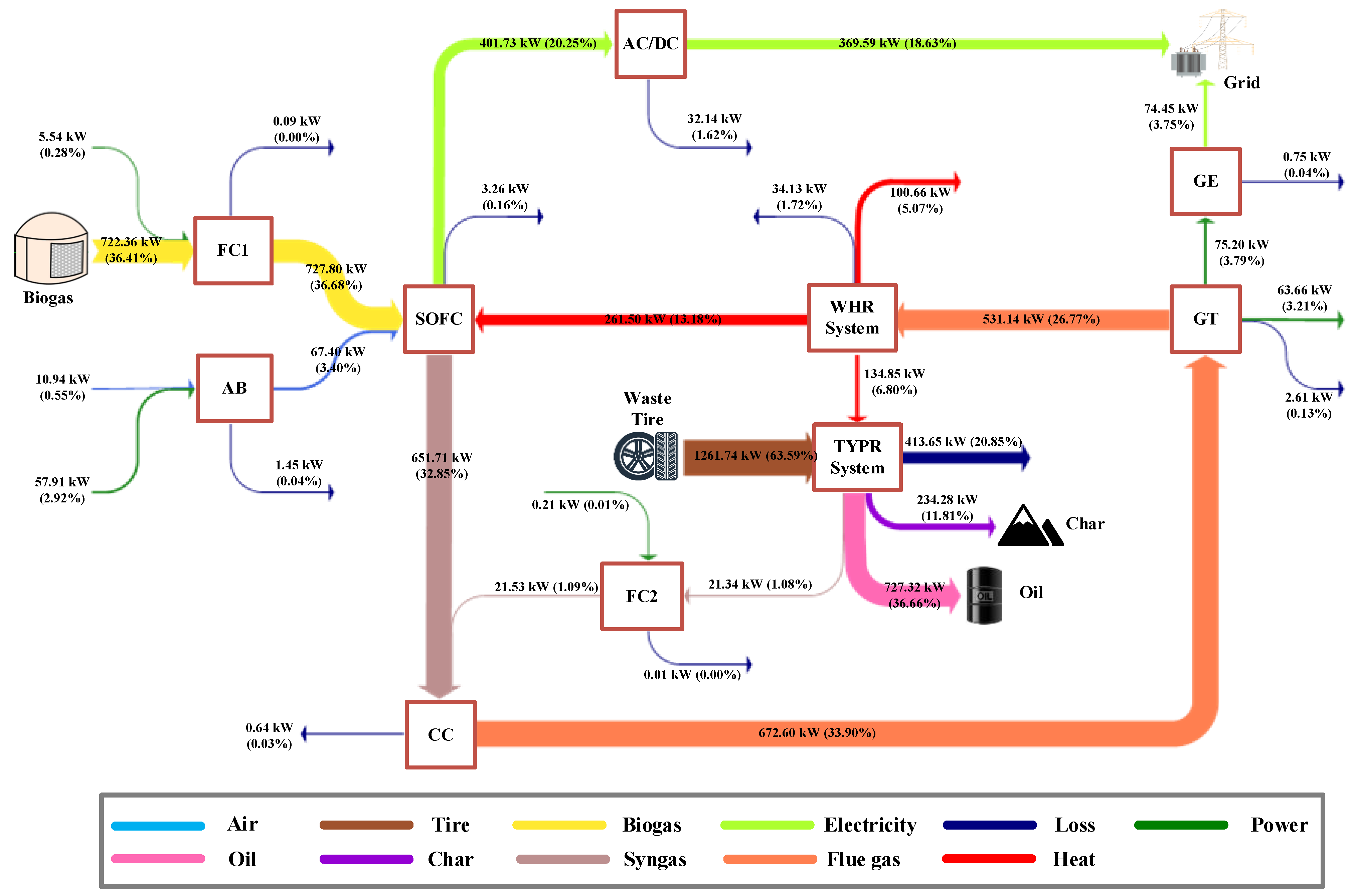
With the same feedstock, biogas, and waste tires can generate a total energy output of 1406.39 kW with a high energy conversion efficiency of 70.88%. Among them, the SOFC subsystem achieves a power generation efficiency of 51.16%, which is an outstanding contribution to the efficiency of the whole system. Thermodynamically, the proposed system is feasible and efficient.
(2)
The exergy efficiency reaches 69.88%. The pyrolysis reactor, SOFC, and combustion chamber contribute to the irreversibility at most, accounting for 59.67%, 18.34%, and 9.63%, respectively. The other components in the proposed system contribute relatively little to the total exergy loss.
(3)
Economically, the investment in the system is low, only 1,045,830 USD. Over its 25-year life span, the NPV is 2,939,130 USD, due to the multiple outputs such as electricity and by-products, subsystem synergies, equipment sharing, and economies of scale. The DPP of the new design is only 4.79 years old. Therefore, the new design is also very suitable in terms of economics.
There have been a few coupled applications for the subsystems involved in the innovative scheme proposed in this paper. However, relatively complex hybrid systems like the one proposed in this paper lack practical grounded examples despite many similar studies analyzing the feasibility. In this study, when discussing and analyzing the heat balance characteristics, the exergy characteristics, and the economic characteristics of the proposed hybrid system, due to the limitations of the authors’ research level and time, only the steady-state characteristics of the program under the design conditions are analyzed. In the actual operation of the system after construction, the system’s internal and external conditions are constantly changing. Therefore, there are inevitable problems in system regulation and control, and the parameters and dynamic characteristics of the innovative system under variable operating conditions need to be further investigated to form a stable scheduling scheme and control strategy.

Author Contributions

Conceptualization, C.X. and H.C.; methodology, C.X., J.L. and T.C.; software, H.C. and J.L.; validation, T.C., H.H. and S.W.; writing—original draft, C.X. and Y.W.; writing—review and editing, H.C. and H.H.; supervision, Y.W. and S.W. All authors have read and agreed to the published version of the manuscript.

Funding

This research is funded by the Research on Game Theory of Multi-energy Storage Projects from the Perspective of the Whole Life Cycle, grant number ZZKJ-2024-18.

Data Availability Statement

Data will be made available on request.

Conflicts of Interest

Authors Cheng Xin, Tianqiong Chen, Huijuan Huo, Shuo Wang and Yudong Wang were employed by the company State Grid Economic and Technological Research Institute Co., Ltd. The remaining authors declare that the research was conducted in the absence of any commercial or financial relationships that could be construed as a potential conflict of interest.

References

  1. Zhang, L.; Li, H.; Hu, T.; Du, X.; Zhou, Y.; Sun, G.; Liu, J. The reduction of the carbon footprint of municipal solid waste management via source classification and supporting strategies: An analysis for the megacity of Shenzhen. Waste Manag. 2024, 187, 145–155. [Google Scholar] [CrossRef] [PubMed]
  2. Jin, C.; Sun, S.; Yang, D.; Sheng, W.; Ma, Y.; He, W.; Li, G. Anaerobic digestion: An alternative resource treatment option for food waste in China. Sci. Total. Environ. 2021, 779, 146397. [Google Scholar] [CrossRef] [PubMed]
  3. Soleimanpour, M.; Ebrahimi, M. Energy and exergy analysis of dry and steam external reformers for a power cycle based on biogas-fueled solid oxide fuel cell. Energy 2024, 305, 132382. [Google Scholar] [CrossRef]
  4. Ran, P.; Ou, Y.; Zhang, C.; Chen, Y. Energy, exergy, economic, and life cycle environmental analysis of a novel biogas-fueled solid oxide fuel cell hybrid power generation system assisted with solar thermal energy storage unit. Appl. Energy 2024, 358, 122618. [Google Scholar] [CrossRef]
  5. Illathukandy, B.; Saadabadi, S.A.; Kuo, P.-C.; Wasajja, H.; Lindeboom, R.E.; Vijay, V.; Aravind, P. Solid oxide fuel cells (SOFCs) fed with biogas containing hydrogen chloride traces: Impact on direct internal reforming and electrochemical performance. Electrochim. Acta 2022, 433, 141198. [Google Scholar] [CrossRef]
  6. Ishaq, M.; Ishaq, H. Performance assessment of biogas-fed solid oxide fuel cell system for municipal solid waste treatment. J. Clean. Prod. 2022, 354, 131702. [Google Scholar] [CrossRef]
  7. Zhou, M.; Xu, Y.; Luo, G.; Sun, R.; Zou, R.; Sun, C.; Li, X.; Yao, H. Influence of low-temperature pyrolysis pretreatment on the co-combustion performance of coal and waste polyvinyl chloride/tire. Fuel 2024, 375, 132675. [Google Scholar] [CrossRef]
  8. Lv, W.; Guo, B.; Wen, Y.; Hu, H.; Jin, L. Fast co-pyrolysis of Naomaohu coal with waste tire under negative pressure. Fuel 2025, 379, 132988. [Google Scholar] [CrossRef]
  9. Zhao, H.; Jiang, T.; Hou, H. Performance analysis of the SOFC–CCHP system based on H2O/Li–Br absorption refrigeration cycle fueled by coke oven gas. Energy 2015, 91, 983–993. [Google Scholar] [CrossRef]
  10. Sun, S.; Li, Z.; Yuan, B.; Sima, Y.; Dai, Y.; Wang, W.; He, Z.; Li, C. A new pathway to integrate novel coal-to-methanol system with solid oxide fuel cell and electrolysis cell. Energy 2024, 304, 132125. [Google Scholar] [CrossRef]
  11. Ismail, H.Y.; Abbas, A.; Azizi, F.; Zeaiter, J. Pyrolysis of waste tires: A modeling and parameter estimation study using Aspen Plus®. Waste Manag. 2017, 60, 482–493. [Google Scholar] [CrossRef]
  12. Arslan, O.; Erbas, O. Investigation on the improvement of the combustion process through hybrid dewatering and air pre-heating process: A case study for a 150 MW coal-fired boiler. J. Taiwan Inst. Chem. Eng. 2021, 121, 229–240. [Google Scholar] [CrossRef]
  13. Doherty, W.; Reynolds, A.; Kennedy, D. Computer simulation of a biomass gasification-solid oxide fuel cell power system using Aspen Plus. Energy 2010, 35, 4545–4555. [Google Scholar] [CrossRef]
  14. Chen, H.; Zhang, M.; Xue, K.; Xu, G.; Yang, Y.; Wang, Z.; Liu, W.; Liu, T. An innovative waste-to-energy system integrated with a coal-fired power plant. Energy 2020, 194, 116893. [Google Scholar] [CrossRef]
  15. Zhang, Y.; Li, B.; Li, H.; Zhang, B. Exergy analysis of biomass utilization via steam gasification and partial oxidation. Thermochim. Acta 2012, 538, 21–28. [Google Scholar] [CrossRef]
  16. Nami, H.; Arabkoohsar, A. Improving the Power Share of Waste-Driven CHP Plants via Parallelization with a Small-Scale Rankine Cycle, a Thermodynamic Analysis. Energy 2019, 171, 27–36. [Google Scholar] [CrossRef]
  17. Curry, N.; Pillay, P. Biogas prediction and design of a food waste to energy system for the urban environment. Renew. Energy 2012, 41, 200–209. [Google Scholar] [CrossRef]
  18. Lamidi, R.O.; Wang, Y.D.; Pathare, P.B.; Roskily, A. Evaluation of CHP for Electricity and Drying of Agricultural Products in a Nigerian Rural Community. Energy Procedia 2017, 105, 47–54. [Google Scholar] [CrossRef]
  19. Lamidi, R.O.; Jiang, L.; Wang, Y.; Pathare, P.B.; Roskilly, A. Techno-economic analysis of a biogas driven poly-generation system for postharvest loss reduction in a Sub-Saharan African rural community. Energy Convers. Manag. 2019, 196, 591–604. [Google Scholar] [CrossRef]
  20. Ahmadi, S.; Ghaebi, H.; Shokri, A. A comprehensive thermodynamic analysis of a novel CHP system based on SOFC and APC cycles. Energy 2019, 186, 115899. [Google Scholar] [CrossRef]
  21. Duan, L.; Huang, K.; Zhang, X.; Yang, Y. Comparison study on different SOFC hybrid systems with zero-CO2 emission. Energy 2013, 58, 66–77. [Google Scholar] [CrossRef]
  22. Roy, D.; Samanta, S.; Ghosh, S. Performance assessment of a biomass-fuelled distributed hybrid energy system integrating molten carbonate fuel cell, externally fired gas turbine and supercritical carbon dioxide cycle. Energy Convers. Manag. 2020, 211, 112740. [Google Scholar] [CrossRef]
  23. Scano, E.A.; Asquer, C.; Pistis, A.; Ortu, L.; Demontis, V.; Cocco, D. Biogas from anaerobic digestion of fruit and vegetable wastes: Experimental results on pilot-scale and preliminary performance evaluation of a full-scale power plant. Energy Convers. Manag. 2014, 77, 22–30. [Google Scholar] [CrossRef]
  24. Baccioli, A.; Ferrari, L.; Vizza, F.; Desideri, U. Potential energy recovery by integrating an ORC in a biogas plant. Appl. Energy 2019, 256, 113960. [Google Scholar] [CrossRef]
  25. Gholizadeh, T.; Vajdi, M.; Mohammadkhani, F. Thermodynamic and thermoeconomic analysis of basic and modified power generation systems fueled by biogas. Energy Convers. Manag. 2019, 181, 463–475. [Google Scholar] [CrossRef]
  26. Holik, M.; Živić, M.; Virag, Z.; Barac, A.; Vujanović, M.; Avsec, J. Thermo-economic optimization of a Rankine cycle used for waste-heat recovery in biogas cogeneration plants. Energy Convers. Manag. 2021, 232, 113897–113908. [Google Scholar] [CrossRef]
  27. Zhao, X.-G.; Jiang, G.-W.; Li, A.; Wang, L. Economic analysis of waste-to-energy industry in China. Waste Manag. 2016, 48, 604–618. [Google Scholar] [CrossRef] [PubMed]
  28. Al-Khori, K.; Bicer, Y.; Boulfrad, S.; Koç, M. Techno-economic and environmental assessment of integrating SOFC with a conventional steam and power system in a natural gas processing plant. Int. J. Hydrogen Energy 2019, 44, 29604–29617. [Google Scholar] [CrossRef]
  29. Zang, G.; Jia, J.; Shi, Y.; Sharma, T.; Ratner, A. Modeling and economic analysis of waste tire gasification in fluidized and fixed bed gasifiers. Waste Manag. 2019, 89, 201–211. [Google Scholar] [CrossRef] [PubMed]
  30. The Notice on Improving Price Policies of Waste-to-Energy Plants. Available online: https://zfxxgk.ndrc.gov.cn/web/iteminfo.jsp?id=19669 (accessed on 28 March 2012).
  31. Khan, S.R.; Ciolkosz, D.; Vasco-Correa, J.; Zeeshan, M. A techno-economic study to evaluate the impacts of feed-stock ratio on commercial scale co-pyrolysis plants of biomass and waste tire. J. Anal. Appl. Pyrolysis 2022, 167, 105699. [Google Scholar] [CrossRef]
  32. Wu, Z.; Zhu, P.; Yao, J.; Zhang, S.; Ren, J.; Yang, F.; Zhang, Z. Combined biomass gasification, SOFC, IC engine, and waste heat recovery system for power and heat generation: Energy, exergy, exergoeconomic, environmental (4E) evaluations. Appl. Energy 2020, 279, 115794. [Google Scholar] [CrossRef]
  33. Kumar, P.; Singh, O. Thermoeconomic analysis of SOFC-GT-VARS-ORC combined power and cooling system. Int. J. Hydrogen Energy 2019, 44, 27575–27586. [Google Scholar] [CrossRef]
  34. Ogorure, O.; Oko, C.; Diemuodeke, E.; Owebor, K. Energy, exergy, environmental and economic analysis of an agricultural waste-to-energy integrated multigeneration thermal power plant. Energy Convers. Manag. 2018, 171, 222–240. [Google Scholar] [CrossRef]
  35. Su, B. Mechanism and System Integration Based on Thermochemical Utilization of Biogas and Solar Energy; University of Chinese Academy of Sciences: Beijing, China, 2019. [Google Scholar]
  36. Petrollese, M.; Cocco, D. Techno-economic assessment of hybrid CSP-biogas power plants. Renew. Energy 2020, 155, 420–431. [Google Scholar] [CrossRef]
  37. Peng, W.; Chen, H.; Liu, J.; Zhao, X.; Xu, G. Techno-economic assessment of a conceptual waste-to-energy CHP system combining plasma gasification, SOFC, gas turbine and supercritical CO2 cycle. Energy Convers. Manag. 2021, 245, 114622. [Google Scholar] [CrossRef]
  38. Lubongo, C.; Congdon, T.; McWhinnie, J.; Alexandridis, P. Economic feasibility of plastic waste conversion to fuel using pyrolysis. Sustain. Chem. Pharm. 2022, 27, 100683. [Google Scholar] [CrossRef]
Figure 1. System structure of the proposed system.
Processes 13 00415 g001
Figure 2. Simulation model’s intrinsic structure of the proposed system.
Processes 13 00415 g002
Figure 3. Hierarchy of SOFC calculations.
Processes 13 00415 g003
Figure 4. Simulation model’s intrinsic structure of an SOFC.
Processes 13 00415 g004
Figure 5. Energy flow diagram of the integrated energy system.
Processes 13 00415 g005
Figure 6. Exergy destruction ratio of the system.
Processes 13 00415 g006
Figure 7. Performance of the polygeneration system under various biogas-to-tire ratios.
Processes 13 00415 g007
Table 1. Composition of animal waste (as-received basis, % wt) [19].
ItemValue
Proximate analysisMar45.04
Far55.04
Var60.30
Aar19.15
Ultimate analysisCar40.73
Har5.17
Oar31.47
Nar2.87
Sar0.61
Table 2. Design parameters of an AD system [17,18,19].
ItemUnitValue
FeedstockFeed ratekg/s2.52
Percentage of animal waste% wt18.53
Total solid% wt10.00
Densitykg/m31040.00
Temperature°C55.00
DigesterOverall volumem33460
Volume for gasm3346
Volume for reactionsm33114
Average retention timeday15
Volume of storage tankm3140
Table 3. Parameters of the raw and clean biogas.
ItemUnitValue
Raw biogasFeed ratekg/s0.09
Composition
(% vol)
Moisture%11.12
CH4%50.60
CO2%36.17
Hydrogen%0.40
Hydrogen sulfide%0.87
Ammonia%0.80
Lower heating valueMJ/kg15.39
Clean biogasFlow ratekg/s0.04
Composition
(% vol)
Methane%58.32
CO2%41.68
Lower heating valueMJ/kg17.69
Table 4. Basic parameters for the SOFC-GT subsystem [10,20,21].
ItemUnitItem
SOFCInlet temperature°C630.00
Operating temperature°C910.00
Operating pressurebar3.04
Active surface areacm2834.20
Number of cells/3456
U f %85.00
S/C ration/2.50
DC-AC inverter efficiency%92.00
i c mA/cm2204.82
Cell voltageV0.68
Afterburner efficiency%99.00
GTIsentropic efficiency%80.00
Mechanical efficiency%98.00
Table 5. Composition of the waste tire (as received basis, % wt) [11].
ItemValue
Proximate analysisMar1.50
Far30.00
Var55.00
Aar13.50
Ultimate analysisCar73.88
Har6.90
Oar2.46
Nar0.30
Sar1.48
LHV (MJ/kg)30.28
Table 6. Basic parameters and results for the tire pyrolysis reaction.
ItemUnitValue
Simulation conditionFeed ratekg/h150.00
Operating temperature°C400.00
Operating pressurebar1.01
Pyrolysis productsCharkg/h27.41
Metalkg/h20.25
Gaskg/h1.68
Oilkg/h94.80
Table 7. Energy performance of the integrated energy system.
ItemUnitValue
Gross power outputSOFCkW369.59
GTkW138.86
SumkW508.45
Pyrolysis product outputOilkW727.32
CharkW234.28
SumkW961.60
Auxiliary consumptionFuel compressor 1 (FC1)kW5.54
FC2kW0.21
Air blower (AB)kW57.91
SumkW63.66
Gross energy outputkW1470.05
Net power outputkW444.79
Net energy outputkW1406.39
Net energy efficiency%70.88
Table 8. Comparison of the current study and previous biogas-based energy systems.
SystemEnergy Conversion EfficiencyReference
Gas Turbine27.00~31.00%[22]
Internal combustion engine (ICE)35.00%[23]
GT or ICE and ORC33.10~35.90%[24]
GT and ORC39.99~41.83%[25]
ICE and steam Rankine cycle43.81~44.95%[26]
Current scheme70.88%/
Table 9. Exergy analysis results of the integrated energy system.
ItemkWRatio
Exergy input of biogas757.8837.00%
Exergy input of waste tire1290.5163.00%
Exergy output (electricity)444.7921.71%
Exergy output (pyrolysis product)986.6248.17%
Total Exergy output1431.4269.88%
Exergy loss
SOFC-GT
subsystem
FC10.720.04%
FC20.030.00%
AB1.500.07%
SOFC108.905.32%
Combustion chamber (CC)57.172.79%
GT14.770.72%
Tire pyrolysis
subsystem
Pyrolysis reactor354.3917.30%
Cyclone0.000.00%
Heat exchanger 5 (HX5)11.160.54%
Distillation column0.000.00%
Waste heat
recovery system
HX17.440.36%
HX229.941.17%
HX37.180.35%
HX46.700.33%
Exhaust gas23.071.12%
Total Exergy loss593.9128.99%
Total Exergy efficiency69.88%
Table 10. Assumptions for the economic evaluation.
ItemUnitValue
Operating time [27]h/year7200
Project lifetime [27]Construction periodyear2
Economic periodyear23
Discount rate [28]/10%
Maintenance & operating cost [27]/10%
Waste tire cost [29]USD/t50.00
Tipping fee [27]USD/t10.39
Feed-in tariff [30]USD/MWh96.51
Oil selling price [31]USD/t370.00
Char selling price [31]USD/t70.00
Table 11. Estimation methods of the investment costs.
Cost Function Method
ComponentFunctionIllustrationreference
SOFCCell stacks A SOFC × N SOFC × ( 2.96 × T SOFC 1907 ) A SOFC represents the active surface area of SOFC; N SOFC represents the number of SOFC cells; T SOFC represents the SOFC operating temperature.[32]
Auxiliary 0.1 × Z SOFC Z SOFC represents the stack cost.
Inverter 10 5 × W SOFC , DC 500 0.7 W SOFC , DC represents the output power of SOFC.
CC 46.08 × m oxidant 0.995 P out P in × e ( 18 1000 T out 26.4 ) + 1 m oxidant represents the mass flow rate of oxidant; T out represents the outlet temperature of combustion chamber; P out represents the outlet pressure of combustion chamber; P in represents the inlet pressure of combustion chamber.[6]
GT 1318.5 × W GT 98.328 × I n W GT W GT represents the power output of GT.[33]
Digester 350,000 × ( V DIG 21,000 ) 0.75 V DIG represents the volume of digester.[34]
Cleaning equipment 141 × e 3 × ( V ˙ biogas 1956 ) 0.6 V ˙ biogas represents the volumetric flow rate of biogas.[35]
Storage tank 48.904 × V tank V tank represents the volume of storage tank.[36]
FC1,2 91,562 × W CM 455 0.67 W CM represents the power consumed by compressor.[37]
HX1,2,3,4 130 × A HXi 0.093 0.78 A HXi represents the heat exchange area of heat exchanger.[32]
Scaling up method
ComponentBasic cost (USD)Basic scaleScale unitScaling factorreference
Pyrolysis reactor244,30030.00TPD0.56[38]
Cyclone11,70030.00TPD0.60
HX587,30030.00TPD0.60
Distillation column97,30030.00TPD0.60
Table 12. Investment costs of the components in the integrated energy system.
ItemCost (×103 USD)
Tire pyrolysis
subsystem
Pyrolysis reactor66.77
Distillation column24.24
HX521.75
Cyclone2.91
Sum115.67
SOFC-GT
subsystem
SOFC559.40
GT182.60
CC5.90
Sum747.90
Waste heat recovery
subsystem
FC and AB28.74
HX1, 2, 3, 428.23
Sum56.97
Anaerobic digestion process125.29
Sum1045.83
Table 13. Economic analysis results.
ItemUnitValue
Waste tire consumption ratet/year1080.00
Animal waste consumption ratet/year12,121.91
Production of electricityMWh/year3202.51
Production of pyrolysis oilt/year682.56
Production of pyrolysis chart/year197.35
Maintenance and operating costUSD/year104,580
Waste tire costUSD/year54,000
Income from animal waste managementUSD/year125,950
Income from electricity saleUSD/year309,070
Income from oil saleUSD/year252,550
Income from char saleUSD/year13,810
DPPyear4.79
NPVUSD2,939,132
Disclaimer/Publisher’s Note: The statements, opinions and data contained in all publications are solely those of the individual author(s) and contributor(s) and not of MDPI and/or the editor(s). MDPI and/or the editor(s) disclaim responsibility for any injury to people or property resulting from any ideas, methods, instructions or products referred to in the content.

