
Numerical Study on the Dynamic Characteristics of a Coupled Wind–Wave Energy Device


Abstract
1. Introduction
2. Coupled Wind and Wave Energy Device
3. Numerical Model Setup and Validation
3.1. Governing Equations
3.2. Numerical Model Setup
3.3. Numerical Model Validation
4. Results and Discussions
4.1. Environmental Conditions
4.2. Modal Analysis
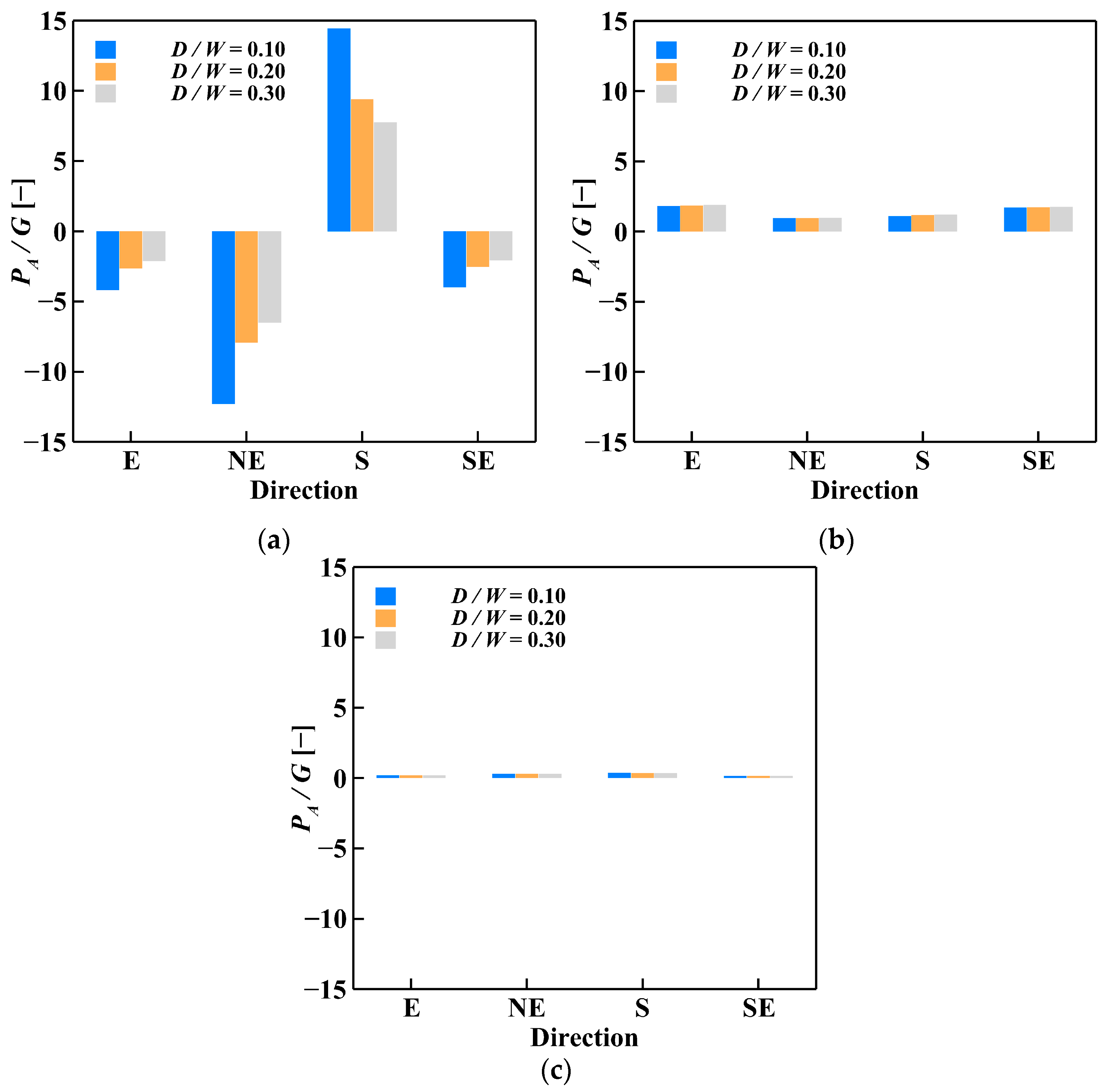
4.3. Dynamic Load and Response Analysis
5. Conclusions
Author Contributions
Funding
Data Availability Statement
Conflicts of Interest
References
- Yue, M.; Liu, Q.; Li, C.; Ding, Q.; Cheng, S.; Zhu, H. Effects of Heave Plate on Dynamic Response of Floating Wind Turbine Spar Platform under the Coupling Effect of Wind and Wave. Ocean Eng. 2020, 201, 107103. [Google Scholar] [CrossRef]
- Dong, X.; Li, Y.; Li, D.; Cao, F.; Jiang, X.; Shi, H. A State-of-the-Art Review of the Hybrid Wind-Wave Energy Converter Progress in Energy RECEIVED. Prog. Energy 2022, 4, 042004. [Google Scholar] [CrossRef]
- Falcão, A.F.d.O. Wave Energy Utilization: A Review of the Technologies. Renew. Sustain. Energy Rev. 2010, 14, 899–918. [Google Scholar] [CrossRef]
- Perez-Collazo, C.; Greaves, D.; Iglesias, G. Hydrodynamic Response of the WEC Sub-System of a Novel Hybrid Wind-Wave Energy Converter. Energy Convers. Manag. 2018, 171, 307–325. [Google Scholar] [CrossRef]
- Aryai, V.; Abbassi, R.; Abdussamie, N.; Salehi, F.; Garaniya, V.; Asadnia, M.; Baksh, A.A.; Penesis, I.; Karampour, H.; Draper, S.; et al. Reliability of Multi-Purpose Offshore-Facilities: Present Status and Future Direction in Australia. Process Saf. Environ. Prot. 2021, 148, 437–461. [Google Scholar] [CrossRef] [PubMed]
- Jiang, C.; Gao, R.; Cao, F.; Shi, H. Structural Energy Transfer to the Jacket Foundation of an Offshore Wind-Wave Coupling Device Based on Absolute Transmissibility Function. Appl. Ocean Res. 2023, 137, 103605. [Google Scholar] [CrossRef]
- Sarmiento, J.; Iturrioz, A.; Ayllón, V.; Guanche, R.; Losada, I.J. Experimental Modelling of a Multi-Use Floating Platform for Wave and Wind Energy Harvesting. Ocean Eng. 2019, 173, 761–773. [Google Scholar] [CrossRef]
- Fenu, B.; Bonfanti, M.; Bardazzi, A.; Pilloton, C.; Lucarelli, A.; Mattiazzo, G. Experimental Investigation of a Multi-OWC Wind Turbine Floating Platform. Ocean Eng. 2023, 281, 114619. [Google Scholar] [CrossRef]
- Aubault, A.; Alves, M.; Sarmento, A.; Roddier, D.; Peiffer, A. Modeling of an Oscillating Water Column on the Floating Foundation WindFloat. In Proceedings of the ASME 2011 30th International Conference on Ocean, Offshore and Arctic Engineering, Rotterdam, The Netherlands, 19–24 June 2011; Volume 5, pp. 235–246. [Google Scholar] [CrossRef]
- Michailides, C.; Gao, Z.; Moan, T. Experimental and Numerical Study of the Response of the Offshore Combined Wind/Wave Energy Concept SFC in Extreme Environmental Conditions. Mar. Struct. 2016, 50, 35–54. [Google Scholar] [CrossRef]
- Wan, L.; Gao, Z.; Moan, T.; Lugni, C. Experimental and Numerical Comparisons of Hydrodynamic Responses for a Combined Wind and Wave Energy Converter Concept under Operational Conditions. Renew. Energy 2016, 93, 87–100. [Google Scholar] [CrossRef]
- Muliawan, M.J.; Karimirad, M.; Moan, T.; Gao, Z. Omae2012-8 Turbine and Large Point Absorber Floating Wave Energy Converter. In Proceedings of the ASME 2012 31st International Conference on Ocean, Offshore and Arctic Engineering, Rio de Janeiro, Brazil, 1–6 July 2012; pp. 1–10. [Google Scholar]
- Perez-Collazo, C.; Pemberton, R.; Greaves, D.; Iglesias, G. Monopile-Mounted Wave Energy Converter for a Hybrid Wind-Wave System. Energy Convers. Manag. 2019, 199, 111971. [Google Scholar] [CrossRef]
- Ahmad, I.; M’zoughi, F.; Aboutalebi, P.; Garrido, I.; Garrido, A.J. Fuzzy Logic Control of an Artificial Neural Network-Based Floating Offshore Wind Turbine Model Integrated with Four Oscillating Water Columns. Ocean Eng. 2023, 269, 113578. [Google Scholar] [CrossRef]
- Michele, S.; Renzi, E.; Perez-Collazo, C.; Greaves, D.; Iglesias, G. Power Extraction in Regular and Random Waves from an OWC in Hybrid Wind-Wave Energy Systems. Ocean Eng. 2019, 191, 106519. [Google Scholar] [CrossRef]
- He, W.; Takahashi, A. Dynamic Response Analysis of Monopile-Supported Offshore Wind Turbine on Sandy Ground under Seismic and Environmental Loads. Soil Dyn. Earthq. Eng. 2025, 189, 109105. [Google Scholar] [CrossRef]
- Dong, X.; Lian, J.; Wang, H. Vibration Source Identification of Offshore Wind Turbine Structure Based on Optimized Spectral Kurtosis and Ensemble Empirical Mode Decomposition. Ocean Eng. 2019, 172, 199–212. [Google Scholar] [CrossRef]
- Jiang, Z. Installation of Offshore Wind Turbines: A Technical Review. Renew. Sustain. Energy Rev. 2021, 139, 110576. [Google Scholar] [CrossRef]
- Cong, P.; Teng, B.; Bai, W.; Ning, D.; Liu, Y. Wave Power Absorption by an Oscillating Water Column (OWC) Device of Annular Cross-Section in a Combined Wind-Wave Energy System. Appl. Ocean Res. 2021, 107, 102499. [Google Scholar] [CrossRef]
- Zhou, Y.; Ning, D.; Shi, W.; Johanning, L.; Liang, D. Hydrodynamic Investigation on an OWC Wave Energy Converter Integrated into an Offshore Wind Turbine Monopile. Coast. Eng. 2020, 162, 103731. [Google Scholar] [CrossRef]
- Jia, J. Soil Dynamics and Foundation Modeling; Springer: Berlin/Heidelberg, Germany, 2018; ISBN 9783319403571. [Google Scholar]
- Ding, X.; Chian, S.C.; Lian, J.; Cao, G.; Shen, J.; Luan, L. Wind-Wave Combined Effect on Dynamic Response of Soil-Monopile-OWT System Considering Cyclic Hydro-Mechanical Clay Behavior. Comput. Geotech. 2023, 154, 105124. [Google Scholar] [CrossRef]
- Iqbal, K.; Xu, C.; Han, Y.; Motalleb, Q.A.; Nadeem, M.; Sun, Y. Numerical Assessment of Offshore Monopile-Soil Interface Subjected to Different Pile Configurations and Soil Features of Arabian Sea in a Frequency Domain. Appl. Ocean Res. 2022, 118, 102969. [Google Scholar] [CrossRef]
- Pezeshki, H.; Pavlou, D.; Adeli, H.; Siriwardane, S.C. Modal Analysis of Offshore Monopile Wind Turbine: An Analytical Solution. J. Offshore Mech. Arct. Eng. 2023, 145, 010907. [Google Scholar] [CrossRef]
- Karpenko, M.; Stosiak, M.; Deptuła, A.; Urbanowicz, K.; Nugaras, J.; Królczyk, G.; Żak, K. Performance Evaluation of Extruded Polystyrene Foam for Aerospace Engineering Applications Using Frequency Analyses. Int. J. Adv. Manuf. Technol. 2023, 126, 5515–5526. [Google Scholar] [CrossRef]
- Zhang, J.; Wang, H. Development of Offshore Wind Power and Foundation Technology for Offshore Wind Turbines in China. Ocean Eng. 2022, 266, 113256. [Google Scholar] [CrossRef]
- Zhang, C.; Zhang, X.; Huang, M.; Tang, H. Responses of Caisson-Piles Foundations to Long-Term Cyclic Lateral Load and Scouring. Soil Dyn. Earthq. Eng. 2019, 119, 62–74. [Google Scholar] [CrossRef]
- Qi, W.G.; Tian, J.K.; Zheng, H.Y.; Wang, H.Y.; Yang, J.; He, G.L.; Gao, F.P. Bearing Capacity of the High-Rise Pile Cap Foundation for Offshore Wind Turbines. In Sustainable Development of Critical Infrastructure, Proceedings of the International Conference on Sustainable Development of Critical Infrastructure 2014, Shanghai, China, 16–18 May 2014; American Society of Civil Engineers (ASCE): Reston, VA, USA, 2014; pp. 413–420. [Google Scholar] [CrossRef]
- Yu, Q.; Yu, H.; Zhou, L.; Meng, A.; Hu, X.; Hou, X. Structural Energy Transfer to the Elevated Pile-Cap Foundation of an Offshore Wind Turbine Based on Extracted Transfer Path Analysis. J. Sound Vib. 2021, 512, 116388. [Google Scholar] [CrossRef]
- ANSYS Inc. Aqwa Theory Manual: Release 2022 R1; ANSYS, Inc.: Canonsburg, PA, USA, 2022; pp. 1–208. [Google Scholar]
- Petroleum and Natural Gas Industries—Specific Requirements for Offshore Structures, Part 4-Geotechnical and Foundation Design Considerations. 2014. Available online: https://www.iso.org/standard/61144.html (accessed on 18 January 2025).
- Zhang, X.-l.; Liu, C.-r.; Wang, P.-g.; Zhang, G.-l. Experimental Simulation Study on Dynamic Response of Offshore Wind Power Pile Foundation under Complex Marine Loadings. Soil Dyn. Earthq. Eng. 2022, 156, 107232. [Google Scholar] [CrossRef]


| Serial No. | Water Level | Mean Water Depth (m) | Incident Wave Direction | Hm (m) | H10% (m) | Tp (s) | Wind Speed (m/s) |
|---|---|---|---|---|---|---|---|
| 1 | EHWL | 21.6 | S | 2.0 | 4.1 | 7.8 | 22.0 |
| 2 | DHWL | 19.8 | S | 1.8 | 3.6 | 7.3 | 22.0 |
| 3 | EHWL | 21.6 | SE | 1.2 | 2.5 | 6.1 | 14.5 |
| 4 | DHWL | 19.8 | SE | 1.2 | 2.4 | 6.0 | 14.5 |
| 5 | EHWL | 21.6 | E | 1.4 | 2.9 | 6.6 | 23.3 |
| 6 | DHWL | 19.8 | E | 1.3 | 2.7 | 6.3 | 23.3 |
| 7 | EHWL | 21.6 | NE | 1.9 | 3.8 | 7.7 | 28.7 |
| 8 | DHWL | 19.8 | NE | 1.8 | 3.6 | 7.4 | 28.7 |
| Layer | Soil Type | Depth of the Layer Bottom (m) | Thickness (m) | Bulk Density (kN/m3) | Cohesive Force (kPa) | Internal Friction Angle (º) |
|---|---|---|---|---|---|---|
| 1 | Silt | 2.5 | 2.5 | 16.0 | 5.0 | 15.0 |
| 2 | Silty clay | 6.5 | 4.0 | 18.0 | 12.0 | 16.0 |
| 3 | Fine sand | 11.7 | 5.2 | 19.0 | 6.0 | 20.0 |
| 4 | Gravel-bearing medium-coarse sand | 14.2 | 2.5 | 22.0 | 35.0 | 25.0 |
| 5 | Strong-weathered granite | 18.7 | 4.5 | 23.2 | 201.0 | 27.0 |
| 6 | Weak-weathered granite | 27.1 | 8.4 | 25.5 | 30,950.0 | 55.0 |
| Order | 1 | 2 | 3 | 4 | 5 | 6 |
|---|---|---|---|---|---|---|
| Natural frequency (Hz) | 0.3212 | 0.3274 | 0.8094 | 0.9510 | 0.9858 | 1.2567 |
| Natural period (s) | 3.1129 | 3.0547 | 1.2355 | 1.0516 | 1.0144 | 0.7958 |
| Order | 1 | 2 | 3 | 4 | 5 | 6 |
|---|---|---|---|---|---|---|
| Natural frequency (Hz) | 0.3213 | 0.3275 | 0.8102 | 0.9489 | 0.9846 | 1.2563 |
| Natural period (s) | 3.1128 | 3.0538 | 1.2343 | 1.0539 | 1.0156 | 0.7960 |
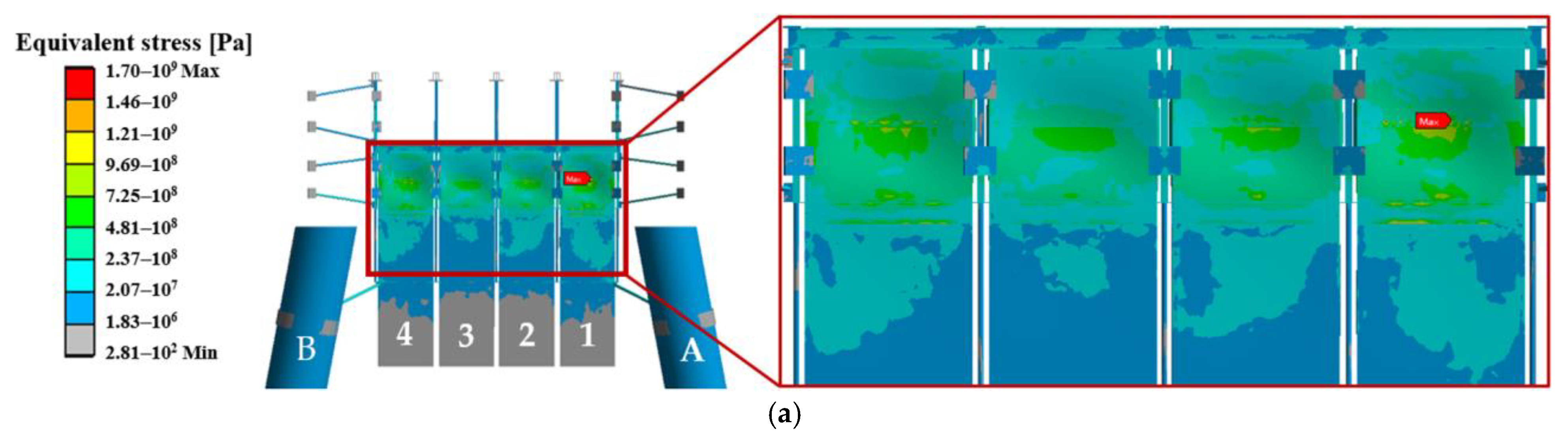
| Incident Direction | D/W | Equivalent Stress on the Pile A (kPa) | Equivalent Stress on the Pile B (kPa) |
|---|---|---|---|
| NE | 0.1 | 1.89 × 10⁴ | 1.65 × 10⁴ |
| 0.2 | 1.63 × 10⁴ | 1.44 × 10⁴ | |
| S | 0.1 | 1.67 × 10⁴ | 1.70 × 10⁴ |
| 0.2 | 1.42 × 10⁴ | 1.44 × 10⁴ |
Disclaimer/Publisher’s Note: The statements, opinions and data contained in all publications are solely those of the individual author(s) and contributor(s) and not of MDPI and/or the editor(s). MDPI and/or the editor(s) disclaim responsibility for any injury to people or property resulting from any ideas, methods, instructions or products referred to in the content. |
© 2025 by the authors. Licensee MDPI, Basel, Switzerland. This article is an open access article distributed under the terms and conditions of the Creative Commons Attribution (CC BY) license (https://creativecommons.org/licenses/by/4.0/).
Share and Cite
Su, X.; Dong, X.; Xu, C.; Liu, Z.; Ni, H.; Han, Z. Numerical Study on the Dynamic Characteristics of a Coupled Wind–Wave Energy Device. Processes 2025, 13, 399. https://doi.org/10.3390/pr13020399
Su X, Dong X, Xu C, Liu Z, Ni H, Han Z. Numerical Study on the Dynamic Characteristics of a Coupled Wind–Wave Energy Device. Processes. 2025; 13(2):399. https://doi.org/10.3390/pr13020399
Chicago/Turabian StyleSu, Xiaoming, Xiaochen Dong, Chuanli Xu, Zhen Liu, Heqiang Ni, and Ziqian Han. 2025. "Numerical Study on the Dynamic Characteristics of a Coupled Wind–Wave Energy Device" Processes 13, no. 2: 399. https://doi.org/10.3390/pr13020399
APA StyleSu, X., Dong, X., Xu, C., Liu, Z., Ni, H., & Han, Z. (2025). Numerical Study on the Dynamic Characteristics of a Coupled Wind–Wave Energy Device. Processes, 13(2), 399. https://doi.org/10.3390/pr13020399