Abstract
To achieve the co-optimization of dynamic–static performance and lightweight design for the telescopic boom, we proposed an integrated approach within a multi-objective optimization framework by using hybrid surrogate model, combined weighting-TOPSIS method, and Monte Carlo simulation (MCS). First, a parametric model of the telescopic boom under extreme working conditions is established, and its dynamic and static performance is analyzed through finite element analysis. Then, using the cross-sectional parameters of the telescopic boom as input variables, design variables with significant influence on the output responses are identified via Spearman correlation analysis. Subsequently, based on sample points obtained by optimal Latin hypercube design, a high-precision RSM-RBFNN hybrid surrogate model is constructed. On this basis, the NSGA-II algorithm is applied to perform multi-objective deterministic optimization of the telescopic boom, and the combined weighting-TOPSIS method is employed to extract optimal solutions from the Pareto solution set. Finally, considering uncertainties in the design variables, 3-Sigma reliability optimization of the telescopic boom is carried out using Monte Carlo simulation. The results show that, while meeting all design requirements, the mass of the telescopic boom is reduced by 12.5%, the second-order natural frequency is improved by 9.4%, and all performance metrics achieved the 3σ level. This study provides practical guidance for the structural optimization design of the telescopic boom.
1. Introduction
Lightweight design is currently a hot topic in the field of special vehicles, among which structural optimization is the most commonly used method [1,2]. Special vehicles are widely used in engineering fields due to their strong maneuverability, versatile operation, and extensive working range [3]. The telescopic boom, as a key load-bearing component of special vehicles, directly affects the performance of the entire machine [4]. The traditional telescopic boom design relies on the experience of designers, leading to relatively conservative designs that increase unnecessary materials without significantly improving structural performance. Therefore, it is of great significance to carry out lightweight design for the telescopic boom while ensuring its dynamic and static performance.
Currently, scholars have conducted extensive research on the lightweight design of telescopic boom. Wang et al. optimized the cross-sectional shape of the crane telescopic arm with mass as the optimization objective, obtaining a reasonable cross-sectional shape [5]. Miromir et al. employed the Lagrange multiplier method and differential evolution algorithm to optimize the cross-sectional parameters of crane boom sections, achieving lightweight design while satisfying strength and stiffness requirements [6]. Liu et al. established a parameterized model of the crane telescopic boom and combined finite element analysis with numerical optimization methods to perform multi-objective optimization of boom mass and deflection, reducing the mass of the telescopic boom [7]. Wang et al. used finite element software to optimize the key cross-sectional parameters of the telescopic boom under dangerous working conditions with mass as the optimization objective, thus achieving lightweight design of the telescopic boom [8]. Zhang et al. took the U-shaped section telescopic boom as the research object and conducted dimensional optimization of the upper cover plate and web plate thickness through Inspire and Ansys software 2023 R1, achieving a weight reduction rate of 15.2% [9]. Rad employed a reliability limit analysis method to address the assessment of ultimate bearing capacity for laterally loaded piles under conditions of uncertainty [10]. Fan et al. took the main beam of a crane as the research subject and introduced reliability constraints into the deterministic optimization model to ensure the probability that the design could still meet performance requirements under the fluctuation of random variables [11]. Rad et al. investigated the plastic limit load capacity and design parameters of long pile foundations under horizontal loads by applying the shakedown method and considering uncertainties [12]. Muayad et al. developed a topology optimization framework based on thermoelastic-plastic behavior and reliability, utilizing an enhanced Bidirectional Evolutionary Structural Optimization (BESO) method. By considering high temperatures, geometric imperfections, and material uncertainties, it achieves efficient and robust design for I-beam structures under thermomechanical loads [13].
Multi-objective optimization methods can simultaneously consider multiple optimization objectives, primarily achieved through the integration of surrogate models with multi-objective optimization algorithms, which have been widely applied in structural lightweight design [14]. Xie et al. employed a Kriging surrogate model combined with the MOGA algorithm to perform multi-objective optimization on a hinge beam structure, achieving lightweight design while meeting strength and stiffness requirements [15]. Chen et al. took the static-dynamic performance and mass of a car body-in-white as optimization objectives, adopted an RBFNN surrogate model integrated with the NSGA-III algorithm to realize lightweight design of the body structure [16]. Based on the RBFNN surrogate model, Ding et al. utilized the NSGA-II algorithm for multi-objective lightweight design of a bogie frame, achieving a 9.59% reduction in frame mass under static strength and fatigue damage constraints [17]. Zhang et al. conducted multi-objective optimization design of a seat suspension structure using the RBFNN surrogate model and MNSGA-II algorithm, obtaining significant vibration reduction effects [18]. Cheng et al. performed multi-objective optimization on the cross-sectional parameters of a pump truck frame longitudinal beam based on an RSM surrogate model and the MOGA algorithm, achieving both lightweight design and improved stiffness performance [19]. Xu et al. employed a RBFNN-QRSM hybrid surrogate model and the PCA-GRA method to conduct a multi-objective optimization integrating structure, connection, and performance, aiming to improve the fatigue and impact performance of a CFRP/aluminum assembled wheel [20]. However, a single surrogate model cannot guarantee sufficient accuracy for all output responses. Moreover, this method generates a large number of non-dominated Pareto solutions during iterative optimization. The Pareto solutions selected by decision-makers based on subjective preferences often fail to achieve the optimal lightweighting effect. Therefore, it is particularly important to select Pareto optimal solutions using both subjective and objective criteria while ensuring the surrogate model possesses adequate accuracy.
Deterministic optimization solutions typically drive the responses to approach constraint boundaries. However, in actual engineering, the uncertainty of design variables may lead to non-compliance with product quality standards [21,22,23]. In contrast, reliability optimization design can enhance the reliability and quality level of products, reducing the impact of uncertainty in design parameters [24]. Among them, 3-Sigma (3) quality design analyzes the impact of random variables on product reliability and quality using probabilistic statistical methods, which is suitable for multi-variable, multi-parameter problems. Some scholars have applied it to certain engineering issues and achieved significant optimization effects. Zhang et al. [25], on the basis of deterministic optimization, incorporated quality level analysis to perform robust optimization on the semi-active suspension of automotive engines, and compared to deterministic optimization, reliability was significantly improved. Dai et al. [26] conducted a multi-objective reliability optimization of a CFRP seat back and pan based on a Kriging surrogate model and the optimal Latin Hypercube design method, taking into account the uncertainty in design parameters, with the aim of improving structural reliability and reducing weight.
In summary, most existing studies on the optimization design of telescopic boom structures focus on single-objective optimization, failing to simultaneously consider both the mass and mechanical performance of the boom, which makes it difficult to meet practical engineering requirements. Additionally, traditional deterministic optimization often overlooks the uncertainties in various design variables, leading to optimization solutions that easily violate constraints in practical applications and lack reliability. Therefore, multi-objective reliability optimization research on telescopic boom structures has not been widely explored. To address this problem, this paper develops a multi-objective reliability optimization framework based on the RSM-RBFNN hybrid surrogate model and Monte Carlo simulation (MCS).
The structure of this paper is organized as follows: Section 2 outlines the framework for multi-objective reliability-based optimization design of the special vehicle telescopic boom. Section 3 establishes a parametric model of the telescopic boom structure and analyzes its mechanical characteristics. In Section 4, a sensitivity analysis is conducted on multiple design variables of the telescopic boom cross-section to identify those with significant influence on the output responses. Furthermore, a high-precision RSM-RBFNN hybrid surrogate model is constructed. In Section 5, reliability optimization of the telescopic boom is performed by employing Monte Carlo simulation (MCS) and the NSGA-II algorithm. Finally, some conclusions are summarized.
2. Optimization Design Framework
The overall process of multi-objective reliability optimization for the telescopic boom structure is shown in Figure 1. First, a parametric model of the telescopic boom is established, and its dynamic and static performance is analyzed. Then, sensitivity analysis using Spearman correlation coefficient is conducted to select variables that significantly affect the output response as design variables. Subsequently, the optimal Latin Hypercube design (OLHD) method is employed to generate sample points for the design variables, and an RSM-RBFNN hybrid surrogate model is constructed. Based on this, the NSGA-II algorithm is used to perform multi-objective deterministic optimization using the hybrid surrogate model, and the combined weighting-TOPSIS method is applied to determine the optimal solution from the Pareto solution set. Finally, the Monte Carlo simulation (MCS) is utilized to conduct a 3-Sigma reliability analysis on the deterministic optimization results, and a reliability optimization mathematical model is established to achieve reliability optimization of the telescopic boom.
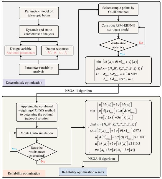
Figure 1.
Overall process of the multi-objective reliability optimization for the telescopic boom.
3. Finite Element Analysis of the Telescopic Boom
3.1. Finite Element Model Establishment
The overall structure of a certain type of telescopic boom is shown in Figure 2. The base boom is hinged to the rotating platform and the luffing cylinder through pin joints, and the intermediate boom and the outer boom are supported by sliders to perform the telescopic operation, with the sliders in surface contact with the boom sections. A parametric model of the telescopic boom for special vehicles is established using SolidWorks 2022. Subsequently, material properties are added to each part of the telescopic boom, with the boom body made of Q460C steel and the sliders made of MC Nylon, as shown in Table 1. Then, the parametric model of the telescopic boom is meshed using SOLID186 elements, and various numbers of grids are used to calculate the maximum stress of the boom under the horizontal (0°) condition to verify mesh independence, with the results shown in Figure 3. When the number of grid elements reaches 54,905 and the average element quality is 0.76507, the maximum equivalent stress is essentially stable, satisfying the requirements for simulation accuracy. Since the analysis in this paper is based on a specific operational posture at a given moment where there is no relative displacement between the boom sections, the contact between the slider and the boom body is simulated using a rigid connection.
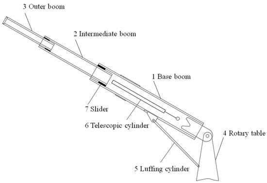
Figure 2.
Telescopic boom structure.

Table 1.
Material properties of telescopic boom.
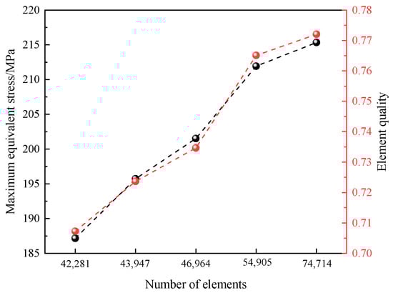
Figure 3.
Mesh independent verification.
3.2. Static Performance Analysis
According to GB/T 3811-2008 [27], the strength and stiffness of the telescopic boom can be verified by selecting dangerous working conditions. Therefore, static analysis can be performed on the fully extended forklift telescopic boom under different luffing angle conditions to identify dangerous working conditions. The main working conditions are shown in Figure 4. The telescopic boom is subjected to various loads in actual operation, including lifting load, self-weight load, wind load, etc. Additionally, when conducting static analysis, the dynamic load coefficient should be considered, with the lifting dynamic load coefficient taken as 1.15. Since the impact of wind load on the luffing plane is relatively small and has considerable uncertainty, it is not considered. Based on the actual working state of the telescopic boom, the designed rated load (1000 kg) is applied to the head of the outer boom. Constraints are applied to the pinholes between the base boom end and the rotating platform, as well as to the pinholes connecting the luffing cylinder and the lug plate on the base boom, retaining only the rotational degree of freedom around the X-axis at these two locations. The applied loads and constraints are shown in Figure 5.
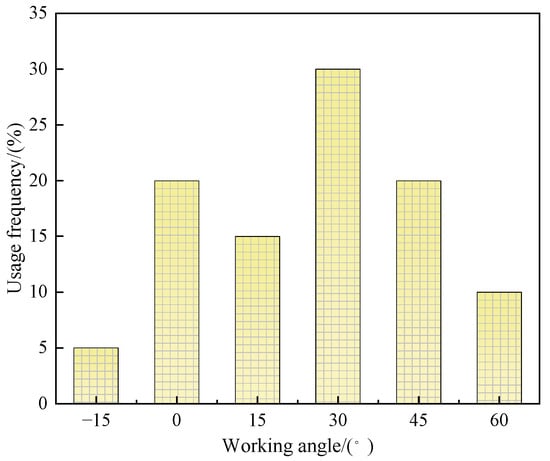
Figure 4.
Different luffing angle conditions of the telescopic boom.
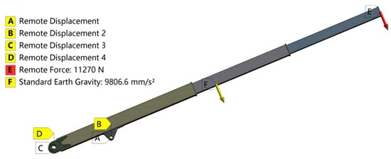
Figure 5.
Boundary condition and mesh structure of the telescopic boom.
In ANSYS software 2023 R1, static analysis of the telescopic boom at different luffing angles revealed that the most hazardous operating condition occurs when the boom is at 0° state, as shown in Figure 6. It can be observed that under this condition, the maximum equivalent stress of the telescopic boom is 211.92 MPa, located at the support of the hydraulic cylinder below the base boom; the maximum deformation occurs at the tip of the outer boom section, with a deformation amount reaching 87.775 mm. The boom material is Q460C steel, with a safety factor of 1.48, and its allowable stress is approximately 310.8 MPa; the total boom length in the fully extended state is 9.89 m, and its allowable deformation in the luffing plane is 97.8 mm. Consequently, the strength and stiffness of this telescopic boom structure meet the design requirements.

Figure 6.
Static analysis results of telescopic boom.
3.3. Dynamic Performance Analysis
Modes represent the fundamental vibration patterns underlying the complex vibrational behavior of engineering structures. Through modal analysis, structural natural frequencies and corresponding mode shapes can be determined. Based on the actual working conditions of the telescopic boom, a constrained modal analysis is performed on the fully extended boom. According to the research findings in reference [8], lower-order modes have a significant impact on the boom structure, so this paper extracts the first six modes of the boom structure, as shown in Table 2. The first two mode shapes of the telescopic boom are shown in Figure 7. Specifically, the first-order mode shape involves lateral oscillation of the boom tip along the Z-axis, while the second-order mode shape features vertical oscillation of the boom tip along the Y-axis.
Table 2.
Results of the constrained modal analysis of the telescopic boom.
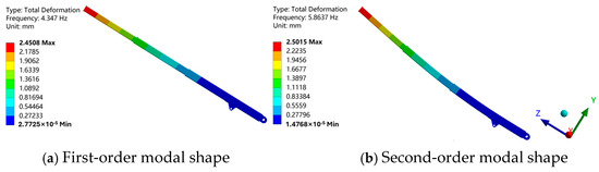
Figure 7.
The first two modal shapes of the telescopic boom.
To investigate the dynamic response of the telescopic boom under different excitation frequencies, harmonic response analysis is further conducted to identify the modal frequency with the greatest influence on its dynamic performance and to obtain the amplitude-frequency response curves at critical locations. Based on the force state during the boom’s operation, a load of −11,270 N is applied along the Y-axis at the tip of the telescopic boom. Using the results from the modal analysis, the excitation frequency range is set from 0 to 70 Hz, with a damping ratio of 0.01, and the modal superposition method is applied to perform the harmonic response analysis of the telescopic boom. Figure 8 shows the amplitude-frequency response curve of the boom tip in the Y-direction.
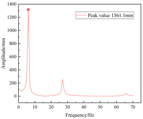
Figure 8.
Y-direction amplitude-frequency response curve of the telescopic boom tip.
As can be seen from the amplitude-frequency response curve, under excitation forces of different frequencies, the peak of the maximum frequency-amplitude response curve at the telescopic boom tip along the luffing plane (Y-direction) occurs at an excitation frequency of approximately 6.0 Hz, with a maximum amplitude reaching 1361.1 mm. This indicates that the second-order natural frequency ( Hz) from the modal analysis has the greatest influence on the vibration of the telescopic boom in the luffing plane, meaning that the second-order natural frequency is likely to cause resonance in the forklift telescopic boom. To reduce the risk of structural damage caused by forced vibration, this paper focuses on the anti-vibration performance of the telescopic boom under low-frequency vibrations during dynamic optimization. The second-order natural frequency is set as the optimization target to avoid resonance as much as possible.
4. Multi-Objective Deterministic Optimization of the Telescopic Boom
4.1. Parameter Sensitivity Analysis
Figure 9 shows the schematic diagram of the cross-sectional shape of the telescopic boom. According to the design specifications of the telescopic boom and practical experience, it is suggested to improve the performance of the telescopic boom by optimizing the boom section parameters. The specific parameters are shown in Table 3. The mass, maximum deformation, maximum equivalent stress, and second-order natural frequency are taken as output variables, Spearman correlation coefficient analysis is employed to evaluate the sensitivity of the nine design variables to each output response. The Spearman correlation coefficient calculation is based on the ranking of two variables. It converts variable values into ranks and computes the differences between these ranks to determine the correlation between two parameters [28]. The expression is as follows:
where represents the number of samples, represents the rank difference between two variables, , and are the ranks of the i-th values of variables and , respectively, arranged in ascending or descending order.

Figure 9.
Schematic diagram of the telescopic boom section.
Table 3.
Range of variation in telescopic boom structural parameters.
To ensure the accuracy of the calculations, correlation analysis is conducted using 40, 60, and 80 groups of sample points. The comprehensive Spearman correlation coefficients for each design variable are calculated using Equation (2), and the results are shown in Figure 10.
where is the comprehensive correlation degree of each design variable; is the Spearman correlation coefficient between design variable and output response , the closer the absolute value is to 1, the stronger the correlation; is the number of output responses.
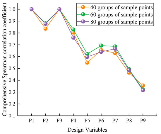
Figure 10.
The comprehensive correlation values calculated with different groups of sample points.
As can be seen from Figure 10, the correlation coefficients of each design variable exhibit minimal variation as the number of sample sets increases, indicating that the sample size has negligible influence on the correlation analysis. Furthermore, it is observed that the fillet radius of the telescopic boom section (P9) has a relatively minor impact on the output responses. Therefore, P9 can be excluded from the design variables in the subsequent multi-objective optimization design.
The correlation coefficients between the design variables and each output response are shown in Figure 11, where red indicates positive correlation and blue represents negative correlation.
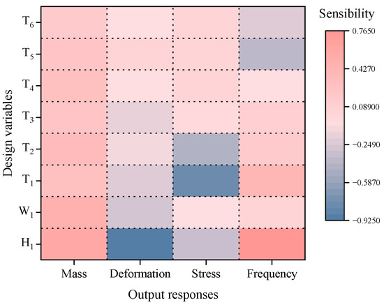
Figure 11.
Correlation matrix graph of design variables.
It can be seen from Figure 11, all design variables have a positive correlation with mass, and P1 and P2 have a significant impact on the mass of the telescopic boom. In contrast, most variables (except P7) have a negative correlation with deformation, among which P1 has the greatest influence on deformation. P3 has the most significant effect on stress, and most variables (including P3) have a negative correlation with stress. For frequency, the most influential variables are P1 and P3, and except for P7 and P8, all other variables have a positive correlation with frequency.
4.2. RSM-RBFNN Hybrid Surrogate Model
The design of experiments for the telescopic boom variables is carried out in the DOE module of Isight software 2024. Optimal Latin Hypercube design (OLHD) [29] is an improved sampling method based on the Latin hypercube design, which ensures a uniform distribution of sample points across the design space, as shown in Figure 12. To ensure the accuracy of the surrogate model, the number of samples required for the experimental design must meet the requirement of [30]. Therefore, the OLHD method is chosen to generate 82 sets of sample points to construct the design matrix. The real response value of each sample point is calculated by ANSYS software 2023 R1.
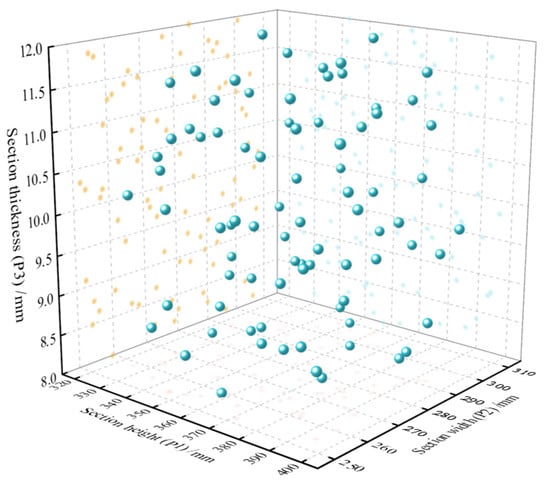
Figure 12.
Spatial distribution of sample points based on OLHD.
As can be seen from Figure 12, the sample points of the design variables selected using the OLHD method are uniformly distributed within the design space, demonstrating good space-filling properties. This allows the accuracy of the constructed surrogate model to be validated across different regions.
To ensure the established surrogate model has sufficient accuracy, 30 sets of sample points are randomly selected to test its prediction accuracy. The predictive accuracy of the surrogate model is evaluated using the coefficient of determination () and the root mean square error () [31]. The expressions are as follows:
where is the number of sample points; is the simulation value of the i-th sample point; is the predicted value obtained for the i-th sample point through the surrogate model; is the average value of . The closer is to 1 and is to 0, the higher the precision of the surrogate model.
Based on the sample points obtained by OLHD sampling, three individual surrogate models—RSM, RBFNN, and Kriging—are constructed to approximate the complex mapping relationships between the design variables and output responses. Additionally, 30 sets of sample points are randomly selected for cross-validation. The fitting accuracy of the three surrogate models is shown in Table 4.
Table 4.
Comparison of prediction accuracy among different surrogate models.
As can be seen from Table 4, no single surrogate model demonstrates superior prediction accuracy over the others for all four responses. Among them, the RSM surrogate model shows relatively better fitting performance for the boom’s mass and deformation, while the RBFNN surrogate model exhibits distinct advantages in predicting maximum stress and second-order natural frequency. In contrast, the Kriging model’s fitting accuracy for all four responses is lower than that of both RSM and RBFNN models. Therefore, to leverage the respective predictive strengths of different surrogate models for various responses in the telescopic boom structure, the RBF neural network and RSM surrogate models are selected for combination to construct an RSM-RBFNN hybrid surrogate model. As shown in Figure 13, the mass and deformation are fitted using the RSM surrogate model, whereas the natural frequency and equivalent stress are approximated using the RBFNN surrogate model.
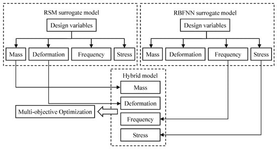
Figure 13.
Hybrid surrogate model structure diagram.
The fitting accuracy of the RSM-RBFNN hybrid surrogate model is shown in Figure 14. It can be observed that the determination coefficients () for mass, maximum deformation, maximum equivalent stress, and second-order natural frequency are 1.0000, 0.9995, 0.9167, and 0.9987, respectively. All values exceed 0.9, indicating that the established RSM-RBFNN hybrid surrogate model demonstrates high fitting accuracy.
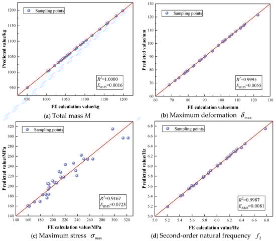
Figure 14.
The fitting accuracy of the RSM-RBFNN hybrid surrogate model.
4.3. Mathematical Model of Multi-Objective Deterministic Optimization
To enhance the overall performance of the telescopic boom structure, the mass, total deformation, and second-order natural frequency of the boom are established as optimization objectives, while stiffness and strength are set as constraints. The following optimization mathematical model is constructed:
where is the mass of the telescopic boom; is the maximum deformation of the telescopic boom; is the second natural frequency of the telescopic boom; is the maximum equivalent stress of the telescopic boom; is the allowable stress; is the allowable stiffness.
NSGA-II is a widely used multi-objective optimization algorithm [32]. Compared to traditional genetic algorithms, it improves the rate of convergence through the use of a fast non-dominated sorting method, an elite preservation strategy, and an efficient crowding distance estimation method, while ensuring the diversity of the population. The optimization process of NSGA-II is shown in Figure 15, and specific steps can be found in Reference [33].
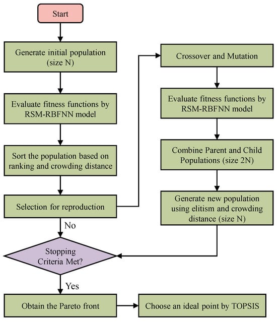
Figure 15.
Flowchart of NSGA-II multi-objective optimization.
In Isight software, the NSGA-II algorithm is applied for the multi-objective deterministic optimization of the telescopic boom, based on the established RSM-RBFNN hybrid surrogate model. The key parameters of the NSGA-II algorithm are set as follows: population size is 20, number of iterations is 80, and crossover probability is 0.9.
Considering the stochastic nature of the NSGA-II algorithm, multiple calculations are performed. After 1600 evaluations of the objective function, a total of 147 non-dominated Pareto solutions are ultimately obtained, as shown in Figure 16. From the Pareto front, it can be observed that none of the Pareto solutions can simultaneously achieve optimal values for the three optimization objectives: mass, deformation, and natural frequency. The improvement of a single objective performance may lead to a decrease in the performance of other objectives, with varying degrees of impact. This makes it challenging for designers to directly select a Pareto optimal solution to achieve overall optimal results.
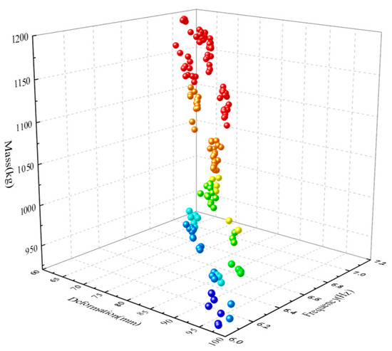
Figure 16.
The distribution of Pareto solution sets.
4.4. Game Combined Weighting-TOPSIS Method
Although the NSGA-II-based multi-objective optimization yields a Pareto solution set, improving one objective often requires sacrificing at least one other. Without extensive engineering experience, it is challenging to select the best compromise solution from the Pareto set. Therefore, it is necessary to assign weights to the output responses to balance multiple conflicting objectives. Traditional weighting methods, such as the Analytic Hierarchy Process (AHP) [34] and entropy weight method (EWM) [35], have certain limitations: AHP relies on the designer’s subjective judgment, while EWM focuses solely on the inherent characteristics of the data and fails to reflect actual decision-making requirements. Consequently, a comprehensive weighting method integrating AHP and EWM based on game theory is adopted to leverage the advantages of both subjective and objective weighting approaches. In this method, the output responses are defined as evaluation indicators, and the comprehensive weighting approach is used to assign weights to each indicator. Subsequently, the TOPSIS method [36] is employed to evaluate the weighted indicators. Finally, based on the evaluation results, all Pareto solutions are ranked, and the overall optimal compromise solution is selected. The specific calculation steps of the combined weighting-TOPSIS method are as follows:
- Using Saaty’s “1–9 scale method” to compare the relative importance between , , and , a comparison judgment matrix is obtained. Subsequently, the consistency ratio of the judgment matrix is calculated using Equation (6). If the consistency test of the judgment matrix is passed, the normalized eigenvector corresponding to the maximum eigenvalue is calculated to determine the subjective weight .
- B.
- Based on the obtained Pareto solution set, the original decision matrix is constructed using Equation (7).
- C.
- Based on the different directions of indicator changes, indicators are categorized into positive and negative. The original decision matrix is normalized using Equations (8) and (9) to obtain the matrix .
- D.
- The objective weights of each evaluation indicator are calculated using Equation (11).
- E.
- To leverage the advantages of both subjective and objective weighting methods, game theory is introduced to minimize the deviation between the combined weights and those derived from different individual methods. The specific theoretical foundation can be found in Reference [37], and the comprehensive weights of each indicator are calculated using Equation (12).
- F.
- The normalized matrix is multiplied by the weight vector obtained from the game theory-based combined weighting method to obtain the weighted normalized decision matrix .
- G.
- Based on the weighted decision matrix , the positive ideal solution and negative ideal solution for the j-th indicator are determined using Equation (14). Then, the relative closeness of all non-dominated Pareto solutions to the positive and negative ideal solutions is calculated using Equation (15). Finally, the globally optimal Pareto solution is further selected based on the values.
In summary, Figure 17 shows the decision-making process for selecting the optimal Pareto solution using the game combined weighting-TOPSIS method.
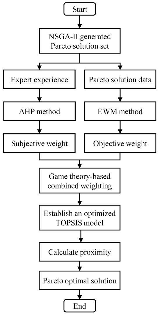
Figure 17.
Decision-making process of game combined weighting-TOPSIS method.
Using the game combined weighting-TOPSIS method, the optimal compromise solution is determined from 147 sets of Pareto solutions. First, the subjective and objective weights for each response are determined using the AHP method and the EWM, respectively. Then, based on game theory, the comprehensive weights for each output response are obtained, as shown in Table 5. Finally, the relative closeness of each Pareto solution is obtained through the TOPSIS method, with the results shown in Figure 18.
Table 5.
Comprehensive weights of various output responses.
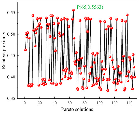
Figure 18.
Analysis results of non-dominated Pareto solutions based on TOPSIS method.
It can be observed that the 65th non-dominated Pareto solution has the highest relative closeness (i.e., point P in Figure 18), meaning that the response values of this alternative solution are closest to the desired values. Therefore, the 65th non-dominated Pareto solution is determined as the optimal solution for multi-objective deterministic optimization.
5. Multi-Objective Reliability Optimization of the Telescopic Boom
5.1. 3-Sigma Reliability Analysis
When conducting deterministic optimization of a structure, if design variables are subject to irregular perturbations, the optimization results may exhibit significant errors, causing the optimal solution to be incorrectly located in the failure region or unable to meet reliability requirements. Implementing low-reliability solutions in production may carry substantial quality risks. Therefore, a 3-Sigma () reliability analysis method is adopted to evaluate the quality level of the optimization results. If the level of output responses is below a specified value, it indicates that the optimization results lack robustness and require further reliability optimization.
In this paper, the Monte Carlo simulation (MCS) descriptive sampling method is employed to evaluate the mean () and standard deviation () of each response. The design variables of the telescopic boom are considered as random variables in the analysis system, which are assumed to follow a normal distribution. The deterministic optimization results are set as the mean values of these random variables, with a coefficient of variation (CV) of 0.02. To ensure the accuracy of the reliability calculations, the Monte Carlo sample size is set to 10,000. After 10,000 calculations, the 3-Sigma reliability analysis results for the deterministic multi-objective optimization of the telescopic boom are obtained, as shown in Figure 19.
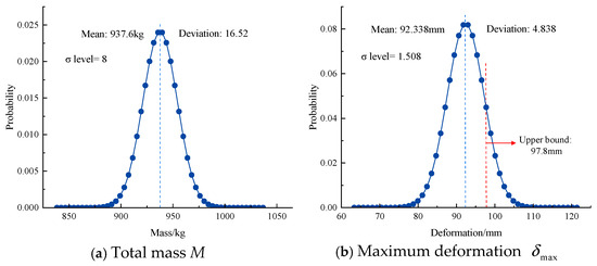
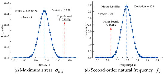
Figure 19.
3-Sigma reliability analysis results of deterministic optimization.
As can be seen from Figure 19, the Sigma level for maximum deformation is 1.508, which is lower than the required 3σ level, and the σ level value of the second-order natural frequency is 3.281. Under the influence of design variable fluctuations, this is highly prone to causing design failure due to the maximum structural deformation exceeding the allowable value and the effects of resonance. Therefore, reliability optimization should be carried out to enhance the robustness of multi-objective optimization design.
5.2. Reliability Optimization of the Telescopic Boom
Based on the 3-Sigma reliability optimization method, defects caused by perturbations in design variables can be eliminated to enhance the robustness of the design. The upper limit for deformation is set to 97.8 mm, the stress constraint upper limit to 310.8 MPa, and the mass upper limit to 1110.3 kg. According to the deterministic optimization model, this paper establishes the multi-objective reliability optimization mathematical model for the telescopic boom as follows:
where , , , , and denote the mean and standard deviation of the corresponding objective functions, respectively, and , represent the mean and standard deviation of the corresponding constraint function, respectively.
The reliability optimization model of the telescopic boom is solved using the NSGA-II algorithm, yielding 83 non-dominated Pareto solutions. The optimal Pareto solution is then selected by employing the combined weighting-TOPSIS method. Subsequently, engineering modifications are applied to the eight optimized variables, and their values are substituted into the parametric model to calculate the corresponding response values. The 6-Sigma reliability optimization results are presented in Table 6.
Table 6.
Reliability optimization results.
A harmonic response analysis is performed on the optimized telescopic boom, with the results shown in Figure 20. It can be observed that the peak value of the maximum frequency-amplitude curve at the boom tip in the Y-direction decreased from 1361.1 mm to 657.24 mm after optimization, representing a reduction of 51.7%. Furthermore, the response peak shifts toward higher frequencies. These results demonstrate a significant improvement in the vibration resistance capability of the telescopic boom.
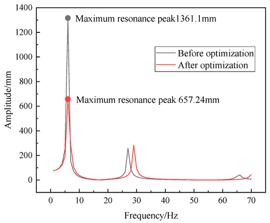
Figure 20.
Y-direction amplitude-frequency response curve at the tip of the optimized telescopic boom.
Table 7 presents a comparative analysis of the results between deterministic optimization and reliability optimization. Compared to the results of deterministic optimization, although the mass has slightly increased, all other performance metrics improved. Except for the maximum deformation, the quality levels of the other three responses reached the 8σ level. The quality level of the maximum deformation increased from 1.508 to 3.59, meeting the reliability design requirements. Compared to the original telescopic boom, after multi-objective reliability optimization, the maximum deformation slightly decreased, the mass reduced from 1110.3 kg to 971.51 kg, a reduction of 12.5%, the second mode frequency increased from 5.8637 Hz to 6.42 Hz, an increase of 9.4%, and the maximum equivalent stress increased by 23.02%, but there is still a large margin, achieving the dual goals of lightweighting and improving dynamic and static performance.
Table 7.
Performance comparison before and after optimization.
6. Conclusions
This study develops a multi-objective reliability optimization framework based on the RSM-RBFNN hybrid surrogate model, combined weighting-TOPSIS method and Monte Carlo simulation (MCS), for the design optimization of the telescopic boom of special vehicles. This framework aims to achieve the simultaneous optimization of lightweighting and reliability of the telescopic boom while ensuring its dynamic and static performance. The main conclusions can be summarized as follows:
- (1)
- A finite element model of the telescopic boom under critical working conditions is established, and its dynamic and static performance is analyzed through finite element analysis. Using the cross-sectional parameters of the telescopic boom as input variables, design variables with significant influence on the output responses are identified through Spearman correlation analysis, thereby improving the efficiency of the optimization process.
- (2)
- A high-precision RSM-RBFNN hybrid surrogate model is constructed. Compared with single surrogate models, the developed model demonstrates higher fitting accuracy. Based on the established hybrid surrogate model, the NSGA-II algorithm is used for multi-objective deterministic optimization of the telescopic boom, resulting in 147 non-dominated Pareto solutions.
- (3)
- The optimal solution is determined from the Pareto solution set using the combined weighting-TOPSIS method. Deterministic optimization results indicate that, while meeting design requirements, the mass of the telescopic boom is reduced by 15.4% and the second-order natural frequency is increased by 5.4%.
- (4)
- To address the uncertainty of design variables, a 3-Sigma reliability design method is employed to conduct multi-objective reliability optimization for the telescopic boom. The results demonstrate that, compared to the initial design, the mass is reduced by 12.5%, the second-order natural frequency is increased by 9.4%, the sigma level of the maximum deformation is elevated to 3.59, and the reliability of the other three response indicators reached the 8σ level. Under the premise of robustness, the dual goals of lightweighting and improvement of dynamic and static performance are achieved.
This study not only provides a new method for the optimal design of telescopic booms but also offers fresh insights into the reliability optimization design of other mechanical structures. The optimization method in this study primarily focuses on the dynamic and static performance of the telescopic boom. However, in practical engineering applications, the boom must withstand not only static loads but also repeated variable loads. In future research, based on the reliability optimization framework used in this study, the objective and constraint functions can be refined to incorporate additional factors such as fatigue performance, buckling stability, and more uncertainties (e.g., material properties, loads), and the optimized results can be integrated and verified at the machine level.
Author Contributions
Conceptualization, S.S. and L.Z.; methodology, L.Z.; software, Z.F.; validation, S.S., Z.F. and J.H.; formal analysis, L.Z.; investigation, S.S.; resources, Z.F.; data curation, J.H.; writing—original draft preparation, L.Z.; writing—review and editing, S.S.; supervision, Z.F. All authors have read and agreed to the published version of the manuscript.
Funding
This research received no external funding.
Data Availability Statement
The original contributions presented in the study are included in the article; further inquiries can be directed to the corresponding authors.
Conflicts of Interest
Author Shijie Sun was employed by the company Henan Hengfa Technology Co., Ltd., he declares no conflicts of interest. The remaining authors declare that the research was conducted in the absence of any commercial or financial relationships that could be construed as a potential conflict of interest.
Abbreviations
The following abbreviations are used in this manuscript:
| RBF | Radial Basis Function Neural Network |
| RSM | Response surface model |
| OLHD | Optimal Latin Hypercube design |
| NSGA-II | Non-dominated Sorting Genetic Algorithm II |
| AHP | Analytic Hierarchy Process |
| EWM | Entropy weight method |
| TOPSIS | Technique for Order Preference by Similarity to Ideal Solution |
| MCS | Monte Carlo simulation |
References
- Xiong, F.; Wang, D.; Ma, Z.; Chen, S.; Lv, T.; Lu, F. Structure-material integrated multi-objective lightweight design of the front end structure of automobile body. Struct. Multidiscip. Optim. 2018, 57, 829–847. [Google Scholar] [CrossRef]
- Xu, F.; Zhang, S.; Wu, K.; Dong, Z. Multi-response optimization design of tailor-welded blank (TWB) thin-walled structures using Taguchi-based gray relational analysis. Thin-Walled Struct. 2018, 131, 286–296. [Google Scholar] [CrossRef]
- Yao, J.; Qiu, X.; Zhou, Z.; Fu, Y.; Xing, F.; Zhao, E. Buckling failure analysis of all-terrain crane telescopic boom section. Eng. Fail. Anal. 2015, 57, 105–117. [Google Scholar] [CrossRef]
- Celik, H.; Rennie, A.; Akinci, I. Design and structural optimisation of a tractor mounted telescopic boom crane. J. Braz. Soc. Mech. Sci. Eng. 2017, 39, 909–924. [Google Scholar] [CrossRef]
- Wang, X.; Huang, L.; Gao, Y.; Gao, S.-D.; Wang, Y.H. Topological optimization for crane telescopic boom-section. J. Dalian Univ. Technol. 2009, 49, 374–379. [Google Scholar]
- Mijailović, R.; Kastratović, G. Cross-section optimization of tower crane lattice boom. Meccanica 2009, 44, 599–611. [Google Scholar] [CrossRef]
- Liu, H.; Zhou, C.; Yu, C. Multi-objective optimization of telescopic boom section for truck-mounted crane. Mach. Des. 2020, 36, 173–176. (In Chinese) [Google Scholar]
- Wang, C.; Xing, B. Optimization of crane telescopic boom structure based on finite element software. SAE Int. J. Mater. Manuf. 2023, 16, 189–201. [Google Scholar] [CrossRef]
- Zhang, L.; Yu, S.; Xu, J.; Zong, X.; Zhang, L. Structural design and cross-section size optimization of crane reach boom for lightweighting objectives. J. Mach. Des. 2023, 40, 124–133. (In Chinese) [Google Scholar]
- Rad, M.M. Reliability based analysis and optimum design of laterally loaded piles. Period. Polytech. Civ. Eng. 2017, 61, 491–497. [Google Scholar] [CrossRef][Green Version]
- Fan, X.; Zhou, J. A reliability-based design optimization of crane metallic structure based on Ant colony optimization and LHS. In Proceedings of the 13th World Congress on Intelligent Control and Automation (WCICA), Changsha, China, 4–8 July 2018; pp. 1470–1475. [Google Scholar]
- Rad, M.M.; Ibrahim, S.K. Optimal plastic analysis and design of pile foundations under reliable conditions. Period. Polytech. Civ. Eng. 2021, 65, 761–767. [Google Scholar] [CrossRef]
- Muayad, H.; Raffaele, C.; Marco, D.; Hamed, F.; Rad, M.M. Thermo-mechanical reliability-based topology optimization for imperfect elasto-plastic materials. Int. J. Mech. Mater. Des. 2025, 1–22. [Google Scholar] [CrossRef]
- Jiang, R.; Sun, T.; Liu, D.; Pan, Z.; Wang, D. Multi-objective reliability-based optimization of control arm using MCS and NSGA-II coupled with entropy weighted GRA. Appl. Sci. 2021, 11, 5825. [Google Scholar] [CrossRef]
- Xie, G.; Zhang, S.; Wang, L.; Gong, X.; Wang, T.; Wang, S.; Chen, Z.; Zhi, Z. Lightweight design of hinge beam based on Kriging agent model. J. Mech. Sci. Technol. 2022, 36, 3585–3595. [Google Scholar] [CrossRef]
- Chen, H.; Lu, C.; Feng, L.; Liu, Z.; Sun, Y.; Chen, W. Structural optimization design of BIW using NSGA-III and entropy weighted TOPSIS methods. Adv. Mech. Eng. 2023, 15, 16878132231220351. [Google Scholar] [CrossRef]
- Ding, L.; He, Z.; Chen, B. Strength assessment and lightweight optimization design of a bogie frame based on the structural stress method. Int. J. Struct. Integr. 2025, 16, 159–186. [Google Scholar] [CrossRef]
- Zhang, S.; Wei, W.; Chen, X.; Xu, L.; Cao, Y. Vibration performance analysis and multi-objective optimization design of a tractor scissor seat suspension system. Agriculture 2022, 13, 48. [Google Scholar] [CrossRef]
- Cheng, L.; Lin, H.; Zhang, Y. Optimization design and analysis of mobile pump truck frame using response surface methodology. PLoS ONE 2023, 18, e0290348. [Google Scholar] [CrossRef] [PubMed]
- Xu, W.; Wang, D. Fatigue/impact analysis and structure–connection–performance integration multi-objective optimization of a bolted carbon fiber reinforced polymer/aluminum assembled wheel. Compos. Part B Eng. 2022, 243, 110103. [Google Scholar] [CrossRef]
- Qiu, N.; Jin, Z.; Liu, J.; Fu, L.; Chen, Z.; Kim, N. Hybrid multi-objective robust design optimization of a truck cab considering fatigue life. Thin-Walled Struct. 2021, 162, 107545. [Google Scholar] [CrossRef]
- Lim, J.; Jang, Y.; Chang, H.; Park, J.; Lee, J. Multi-objective genetic algorithm in reliability-based design optimization with sequential statistical modeling: An application to design of engine mounting. Struct. Multidiscip. Optim. 2020, 61, 1253–1271. [Google Scholar] [CrossRef]
- Fang, J.; Gao, Y.; Sun, G.; Li, Q. Multiobjective reliability-based optimization for design of a vehicledoor. Finite Elem. Anal. Des. 2013, 67, 13–21. [Google Scholar] [CrossRef]
- Najlawi, B.; Nejlaoui, M.; Affi, Z.; Romdhane, L. Multi-objective robust design optimization of a sewing mechanism under uncertainties. J. Intell. Manuf. 2019, 30, 783–794. [Google Scholar]
- Zhang, Z.; Zheng, L.; Xue, W.; Wu, X.; Liao, G. Robust optimization design for vehicle SEM based on 6 method. J. Vib. Shock. 2020, 39, 243–249. [Google Scholar]
- Dai, C.; Yu, P.; Long, J. Study on multilevel optimization strategy of carbon fiber-reinforced polymer seatback and seat pan. Int. J. Mech. Mater. Des. 2025, 21, 209–228. [Google Scholar] [CrossRef]
- GB/T 3811-2008; Design Rules for Cranes. Standards Administration of China (SAC): Beijing, China, 2008.
- Lv, Y.; Lin, L.; Guo, H.; Tong, C.; Liu, Y.; Zhang, S.; Suo, S. An adaptive hybrid surrogate model for FEA of telescopic boom of rock drilling jumbo. Eng. Appl. Artif. Intell. 2024, 130, 107710. [Google Scholar] [CrossRef]
- Shi, L.; Sun, B. Modeling and optimization of vibration response characteristics of the orbital sander based on surrogate model. Struct. Multidiscip. Optim. 2018, 57, 2259–2271. [Google Scholar] [CrossRef]
- Shi, L.; Yang, T.; Ma, J.Y.; Huang, L.; Tian, A.; Xuan, Y.; Tian, Y.; Gao, R. Structural optimization and mechanical property analysis of butterfly valves based on Kriging surrogate model. Build. Environ. 2025, 113343. [Google Scholar] [CrossRef]
- Li, F.; Yuan, W.; Ma, Y.; Fu, J. Structural performance analysis and optimization of small diesel engine exhaust muffler. Processes 2024, 12, 2186. [Google Scholar] [CrossRef]
- Zhou, Y.; Cao, S.; Kosonen, R.; Hamdy, M. Multi-objective optimisation of an interactive buildings-vehicles energy sharing network with high energy flexibility using the Pareto archive NSGA-II algorithm. Energy Convers. Manag. 2020, 218, 113017. [Google Scholar] [CrossRef]
- Xia, L.; Khosravi, A.; Han, M.; Sun, L. Artificial intelligence based structural optimization of solid oxide fuel cell with three-dimensional reticulated trapezoidal flow field. Int. J. Hydrog. Energy 2023, 48, 28131–28149. [Google Scholar] [CrossRef]
- Liu, F.; Tian, Z. Multi-objective optimization decision-making of an underwater vehicle rotary docking skirt structure. Thin-Walled Struct. 2023, 192, 111097. [Google Scholar] [CrossRef]
- Zhu, Y.; Tian, D.; Yan, F. Effectiveness of entropy weight method in decision-making. Math. Probl. Eng. 2020, 2020, 3564835. [Google Scholar] [CrossRef]
- Aentung, T.; Patcharavorachot, Y.; Wu, W. Co-gasification of plastic waste blended with biomass: Process modeling and multi-objective optimization. Processes 2024, 12, 1906. [Google Scholar] [CrossRef]
- Zhou, X.; Tan, W.; Sun, Y.; Huang, T.; Yang, C. Multi-objective optimization and decision making for integrated energy system using STA and fuzzy TOPSIS. Expert Syst. Appl. 2024, 240, 122539. [Google Scholar] [CrossRef]
Disclaimer/Publisher’s Note: The statements, opinions and data contained in all publications are solely those of the individual author(s) and contributor(s) and not of MDPI and/or the editor(s). MDPI and/or the editor(s) disclaim responsibility for any injury to people or property resulting from any ideas, methods, instructions or products referred to in the content. |
© 2025 by the authors. Licensee MDPI, Basel, Switzerland. This article is an open access article distributed under the terms and conditions of the Creative Commons Attribution (CC BY) license (https://creativecommons.org/licenses/by/4.0/).