1. Introduction
Uninterruptible Power Supply (UPS) systems are vital for maintaining continuous power in hospitals, data centers, and industrial plants, where even brief interruptions can result in severe operational or financial losses [
1,
2]. Conventional battery-based UPS systems face serious limitations under sudden load variations such as 1000–2000 W step changes [
3]. These events lead to large battery current stress, voltage overshoot at the DC bus, and increased current ripple, which accelerate battery aging and reduce overall efficiency [
4,
5]. To overcome these problems, Hybrid Energy Storage Systems (HESS) that combine batteries and ultracapacitors have gained significant attention because they merge the high energy density of batteries with the fast power response of ultracapacitors [
6,
7].
Previous studies have explored various power and energy management strategies that involve hybrid combinations of batteries, fuel cells, and ultracapacitors [
8,
9]. Other works have provided reviews highlighting challenges in UPS design and opportunities for hybridization to improve performance and lifetime [
10,
11]. Research on energy storage technologies confirmed that hybrid battery–ultracapacitor systems can significantly improve transient response and system reliability [
12,
13].
Advanced control techniques have been developed to optimize the dynamic performance of UPSs [
14]. Model predictive and disturbance-observer-based controllers have achieved precise output voltage regulation but without direct ultracapacitor coordination during rapid load transients [
15,
16]. Deadbeat and observer-based control approaches reduced voltage error and settling time but did not prevent peak battery current during large load steps [
17,
18]. Other hybrid system studies, focusing on microgrids and electric vehicle systems, have emphasized that delay, frequency-sharing, and load-balancing parameters strongly influence transient power allocation [
19].
Research in related applications has shown that hybrid configurations can reduce peak load and extend storage lifetime [
20]. For instance, hybrid battery–ultracapacitor systems used in data centers achieved a 30–50% reduction in peak load and lowered battery current by nearly 25% during transient events [
21]. Experimental results from hybrid storage prototypes indicated that ultracapacitor assistance can decrease battery ripple current by approximately 40% and lower the temperature rise by about 5 °C under pulsed loads [
22]. These results underline the potential of hybrid storage in mitigating battery degradation during sudden power fluctuations.
Modeling and sizing investigations have demonstrated that the converter topology and losses directly impact energy-sharing efficiency under high-power conditions [
23]. Experimental findings further confirmed the positive effect of hybrid configurations in reducing DC bus overshoot and stabilizing current profiles during transient conditions [
24].
Some works have reported hybrid control algorithms that maintain DC bus voltage overshoot below 3% under 1200 W step loads [
25]. Experimental studies such as demonstrated that ultracapacitor-assisted operation can reduce battery current ripple by about 30% under moderate load steps around 1500 W [
26]. Real-time algorithms managing up to five operating modes were shown to maintain the DC bus voltage variation within ±2% [
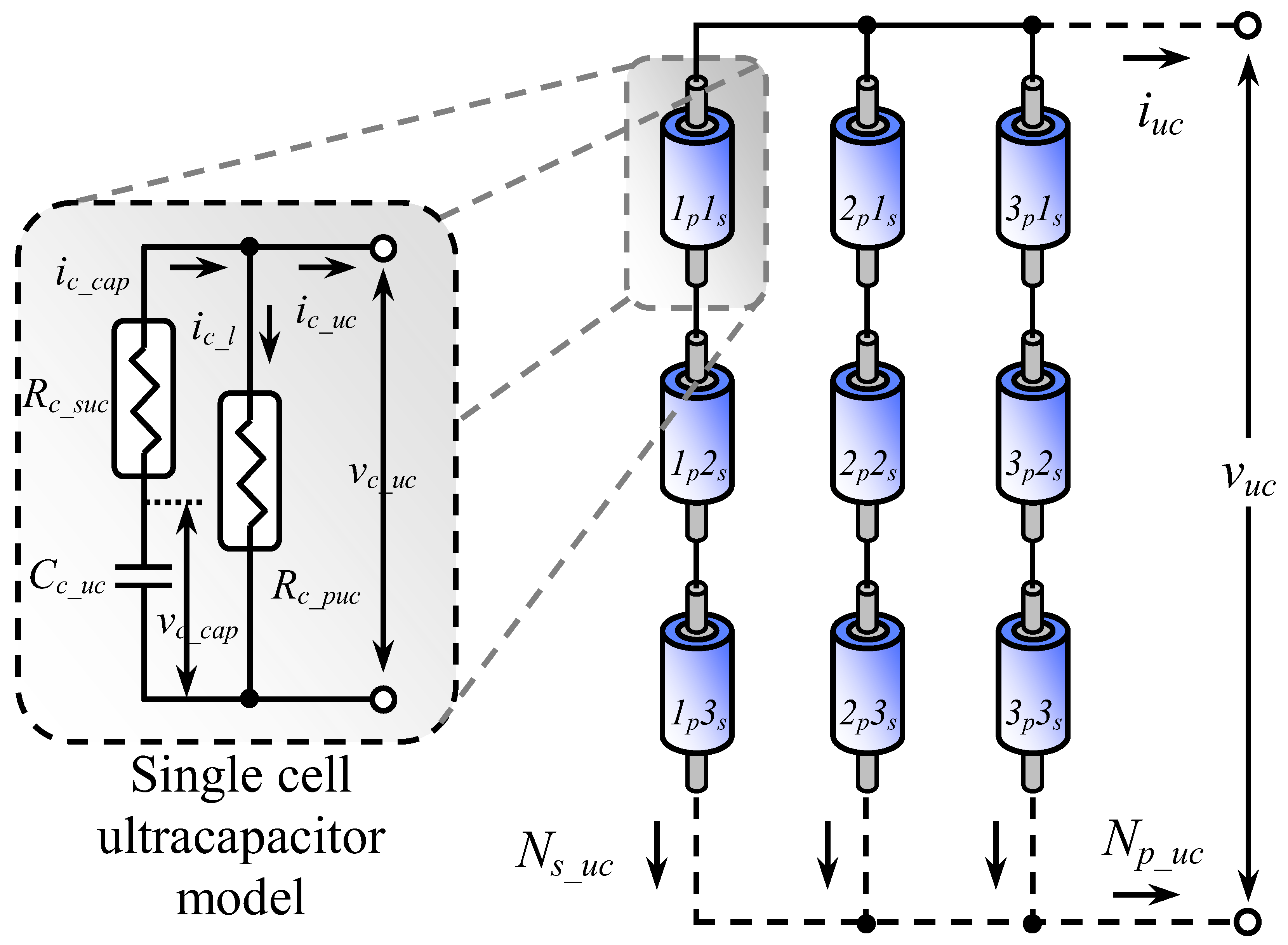
27]. Improved modeling of ultracapacitor equivalent series resistance (ESR) and leakage parameters enabled more accurate prediction of transient behavior [
28]. Other studies have integrated machine learning for state-of-charge estimation, achieving roughly 15% higher accuracy [
29]. Finally, a hospital UPS case study revealed that ultracapacitor support can reduce peak battery current by approximately 35% under critical load conditions [
30].
Although significant progress has been achieved, several issues remain open. However, most existing control algorithms have been validated only through simulations or under smaller dynamic load variations—typically below 1000 W—while practical UPS systems are often subjected to faster and higher power transitions. Quantitative experimental verification covering all operating modes within a unified control framework remains limited. Furthermore, decision thresholds between battery-only, ultracapacitor-assist, and hybrid modes are not standardized, and few works evaluate battery stress, transient stability, and efficiency simultaneously. Literature has demonstrated hybrid UPS operation under load variations up to 1500 W; their approaches mainly focused on steady-state hybrid energy sharing and lacked real-time dynamic mode-switching capability. The present study builds upon these works by introducing a unified control algorithm capable of managing five operating modes, thereby enabling seamless coordination among the battery, ultracapacitor, and grid. Unlike earlier research limited to partial transient verification, the proposed algorithm provides full-scale dynamic validation under 1500–2250 W load transitions, confirming its robustness, adaptability, and practical applicability in high-power UPS systems.
Recent studies have highlighted that lithium-ion batteries are susceptible to microstructural degradation and thermal runaway, particularly under high-rate cycling and fluctuating load conditions [
31]. Such safety concerns underscore the importance of developing hybrid energy storage systems that integrate batteries and ultracapacitors to mitigate current stress, temperature rise, and potential fire hazards during dynamic operation.
Beyond microstructural degradation, recent findings suggest that encapsulation and wrapping materials have a significant influence on the onset of thermal runaway, heat release, and propagation pathways in LIBs, underscoring packaging as a primary safety variable rather than an afterthought. Comparative assessments further indicate divergent hazard profiles among next-generation chemistries and formats (e.g., solid-electrolyte cells, sodium-based systems), with trade-offs between ionic conductivity, thermal stability, and venting behavior that directly affect abuse tolerance. These results highlight that control strategies must complement cell-level safety by actively moderating current peaks and temperature rise during transients—precisely the role targeted by our battery–ultracapacitor coordination. In this context, the proposed DEMA explicitly limits surge currents and shares peak power with the UC, thereby mitigating conditions that precipitate thermal events while preserving UPS performance [
32].
Millner et al. proposed a self-assembled functional interfacial layer that promotes preferential sodium adsorption and enhances the long-term cycling stability of sodium metal batteries, demonstrating remarkable resistance to dendrite formation under high-rate operation [
33]. Similarly, Vetter et al introduced a trifunctional halogenated covalent organic framework (COF) separator that can regulate the formation of a NaF-rich solid electrolyte interphase (SEI) layer, effectively prevent dendritic growth, and improve the overall safety and cycle life of sodium metal batteries [
34].
In this study, a Dynamic Energy Management Algorithm (DEMA) is proposed to address the aforementioned gaps in hybrid battery–ultracapacitor UPS systems. The algorithm defines five distinct operating modes—battery-only, ultracapacitor-assist, hybrid-share, grid-connected, and sudden load step—and dynamically adjusts energy flow according to real-time power demand and state of charge. Simulation and experimental validations are conducted for load steps up to 1500 W using an energy analyzer and oscilloscope. Results show that DEMA maintains DC bus voltage overshoot within ±2%, reduces battery current ripple by 30–40%, and suppresses transient peak currents through ultracapacitor assistance. Overall, the proposed method enhances transient performance, minimizes battery stress, and improves energy utilization efficiency compared with conventional control schemes.
As the flow in the study,
Section 2 Modeling of Hybrid UPS System presents the mathematical and electrical models of the hybrid configuration, including the battery, ultracapacitor, bidirectional DC/DC converters, and DC bus behavior under variable and step loads.
Section 3 Dynamic Energy Management Algorithm details the structure and logic of DEMA, explaining how it determines mode switching, energy distribution, and transient compensation during a 1500 W step load.
Section 4 Experimental Study and Results provides both simulation and laboratory validation for the five operating modes—grid-connected, battery-only, ultracapacitor-assist, hybrid-share, and transient step—reporting voltage stability, current ripple, and overall efficiency. Finally,
Section 5 Conclusion summarizes the main outcomes, compares DEMA with previous methods, and highlights its potential to extend battery life and improve UPS reliability.
3. Dynamic Energy Management Algorithm
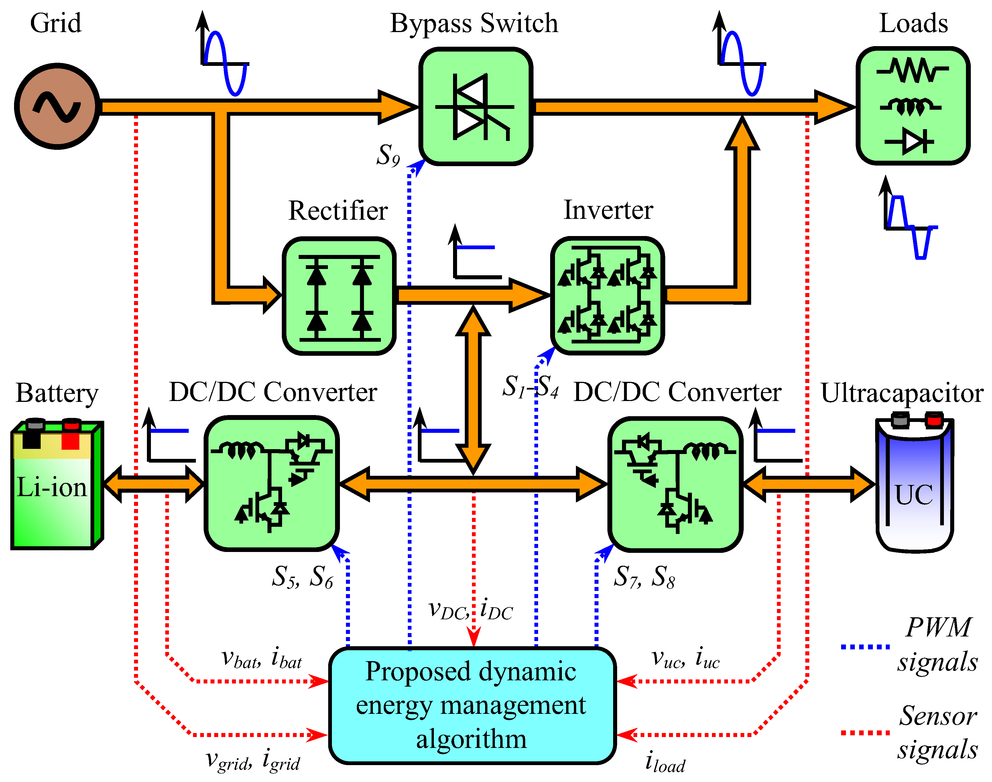
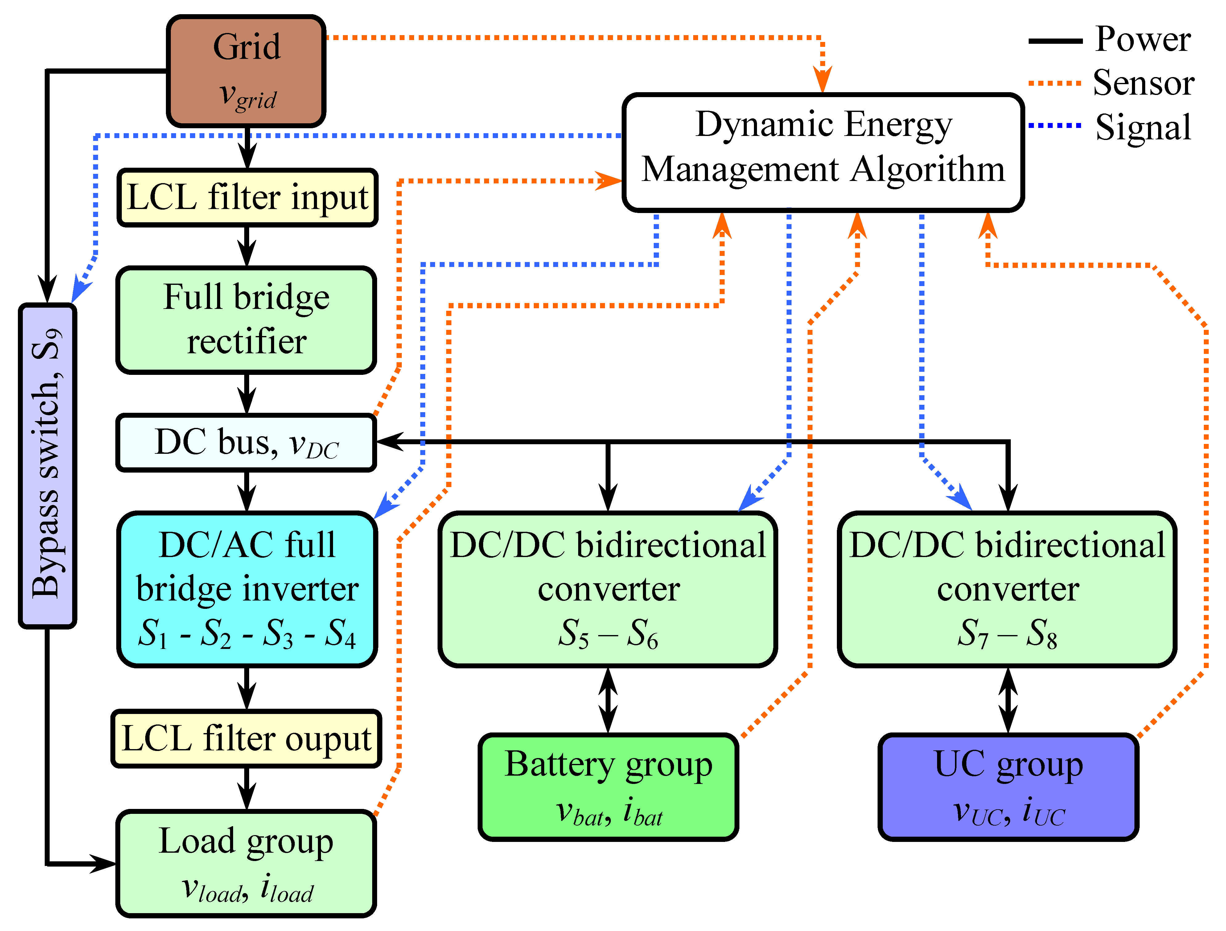
The proposed DEMA governs the overall operation of the hybrid UPS system by monitoring system parameters in real time and dynamically controlling power flow among the grid, battery, ultracapacitor, and load. The complete control topology and algorithmic structure are illustrated in
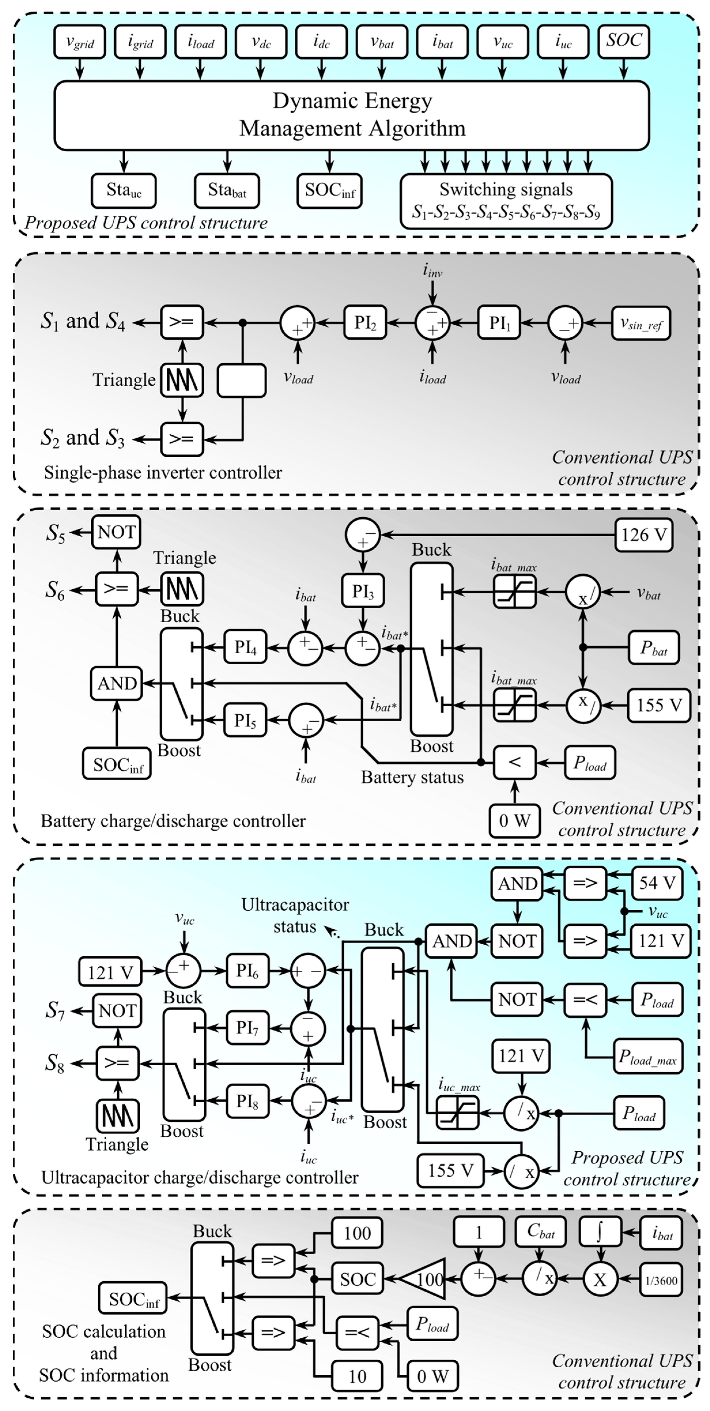
Figure 4, which presents the interconnection between sensing, decision, and actuation blocks. DEMA receives inputs such as the DC bus voltage (155 V nominal), grid voltage (110 V rms), battery and ultracapacitor voltages, currents, and the State of Charge (SOC) of the battery. According to these inputs, it determines the appropriate operating mode and issues gate control signals to the semiconductor switches. The control structure integrates multiple subsystems, including the inverter control for supplying the load during grid failure, the bidirectional converter control for both the battery and UC branches, and the SOC estimation and protection mechanism.
When the grid is available, the system primarily operates in grid-supplied or battery-charging mode, maintaining the DC bus voltage at 155 V through the controlled rectifier. Once a grid outage occurs, the inverter stage immediately becomes active to sustain uninterrupted load power. The inverter control employs a virtual sinusoidal reference generator that defines the target load voltage waveform. This reference is compared with the actual load voltage, and the resulting error is processed by a proportional–integral (PI) controller. The difference between load current and inverter output current is added to the PI output and passed through a secondary PI regulator to refine the dynamic response. The corrected reference voltage is then compared with a triangular carrier to generate Pulse-Width Modulation (PWM) signals for the four inverter switches (S1–S4). This control ensures that the inverter maintains a sinusoidal output and regulates the load voltage under both steady-state and transient conditions, even when the grid is disconnected.
The battery control subsystem governs charging and discharging through a bidirectional DC/DC converter that operates in either buck or boost mode. During normal grid-connected operation, the DC bus supplies energy to charge the battery using the buck configuration. The charging process is regulated based on the battery voltage and SOC level, with the maximum battery charging voltage limited to 126 V. When the grid fails and the load power demand (Pload) exceeds zero, the algorithm automatically switches to the boost mode, allowing the battery to discharge energy into the DC bus to maintain system voltage stability. Within this control loop, voltage and current regulators based on PI controllers ensure smooth transitions and protect against overcurrent conditions. The converter switches S5 and S6 are modulated by DEMA, which continuously monitors battery voltage and SOC thresholds. The battery is prevented from over-discharge, entering recharge mode once the SOC drops to the minimum level of 10%, and ceasing charging when the SOC reaches 100%.
The ultracapacitor control subsystem operates similarly through another bidirectional converter with switches S7 and S8. It supports both buck and boost operation modes depending on the ultracapacitor voltage and system conditions. During low-voltage conditions, the ultracapacitor is charged from the DC bus in buck mode until it reaches the upper limit of 121 V. When the grid is lost and the load power exceeds the defined threshold of Pload_max = 500 W, the converter transitions into boost mode, allowing the ultracapacitor to discharge energy to the DC bus. This behavior provides instantaneous power support to the battery, reducing its current ripple and transient stress. The minimum discharge voltage of the ultracapacitor is maintained at 54 V, ensuring that it does not undergo deep discharge, which could otherwise degrade its capacitance and dynamic response. The use of PI controllers within the voltage and current feedback loops provides stable regulation during rapid charge and discharge transitions, allowing smooth coordination between the ultracapacitor and battery subsystems.
The SOC estimation mechanism is integrated within DEMA to evaluate the battery’s remaining energy in real-time. SOC is computed by integrating the battery current over time and normalizing it with respect to the rated capacity. This enables the algorithm to decide mode transitions effectively—for example, switching from discharge to charge when the SOC reaches the lower boundary of 10%. SOC information also helps balance the energy flow between the battery and ultracapacitor, ensuring that the ultracapacitor primarily manages transient power fluctuations, while the battery handles steady-state energy delivery.
The overall coordination among these subsystems is managed through the DEMA decision layer. This layer processes sensor signals (voltages, currents, and State of Charge, or SOC) and generates PWM commands for all switches (S1–S8). Additionally, a Solid-State Relay (SSR) switch S9 functions as a bypass control between the grid and the load. When the grid is present, S9 remains closed to connect the grid directly to the load for maximum efficiency. However, during a grid outage, DEMA opens S9 to isolate the grid and activate the inverter, ensuring an uninterrupted supply through the battery–ultracapacitor hybrid source.
For reproducibility, the numerical gains of all PI controllers used in the implementation are provided in
Table 1, aligned with the block identifiers in
Figure 4 (PI
1–PI
8). These gains were used throughout the experiments reported in
Section 4. Inner loops employ fixed-gain PI (anti-windup, feedforward, bumpless transfer) tuned for stable margins on the target MCU. PI remains sensitive to plant variation and nonlinearities. Gain-scheduled PI and disturbance-observer-aided PI with hard gain bounds provide enhanced robustness while preserving safety.
The described control topology allows real-time adaptability to various operational conditions. Under nominal grid operation, the system maintains DC bus voltage and keeps both storage devices in balanced charge states. During sudden load changes or grid interruptions, the ultracapacitor immediately compensates for transient power imbalances, thereby minimizing DC bus voltage deviations and battery current ripples. Once the transient period ends, the control smoothly transitions power delivery back to the battery. This dynamic coordination among converters and the inverter ensures high power quality, reduced stress on storage components, and extended battery lifetime. Overall, the control strategy shown in
Figure 4 demonstrates a comprehensive hierarchical structure that integrates sensing, decision-making, and actuation layers to achieve stable hybrid UPS operation under diverse load and grid conditions.
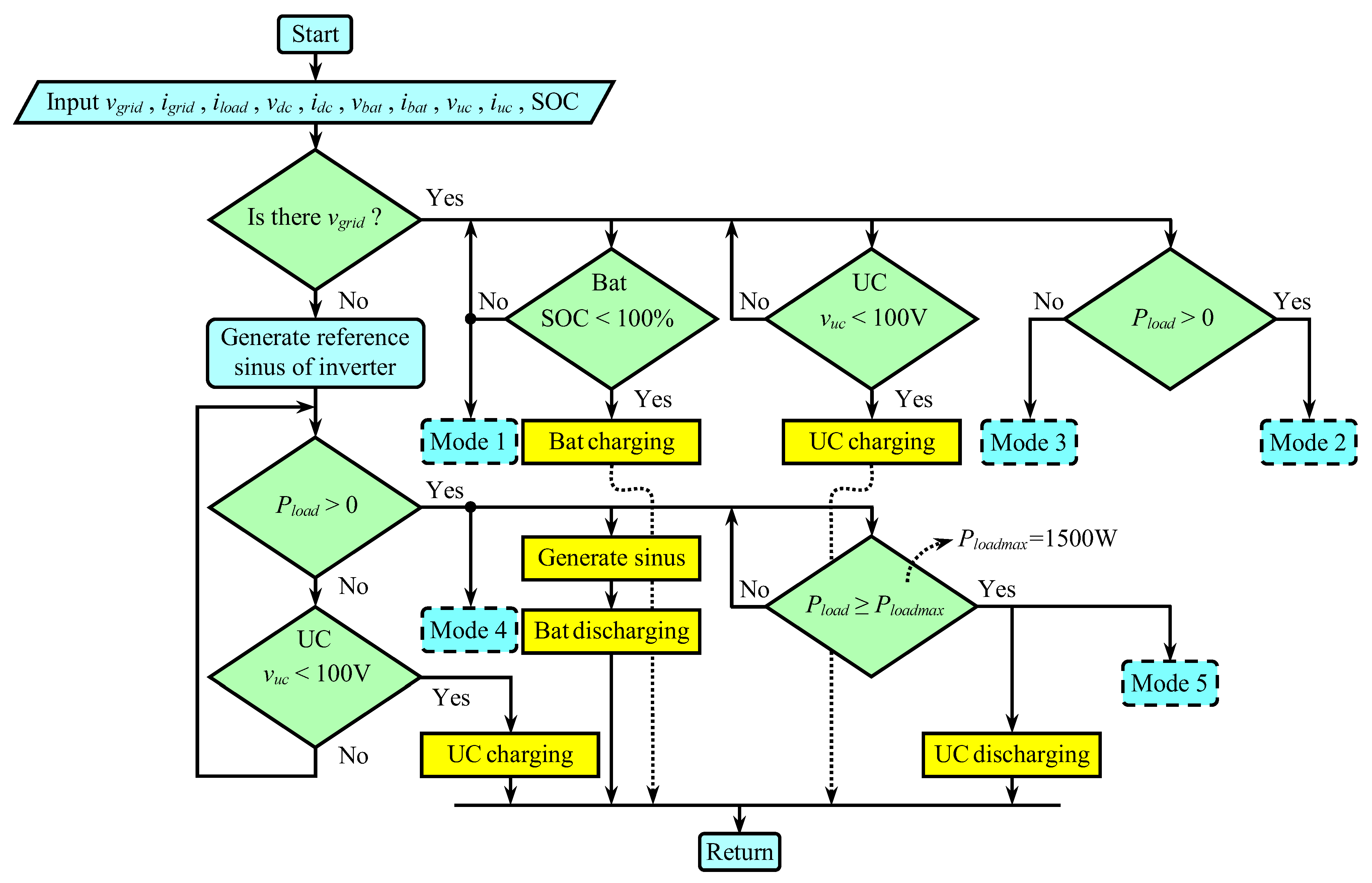
The proposed DEMA, illustrated in
Figure 5, governs the hybrid UPS system through a hierarchical decision process based on real-time measurements. At each sampling period, the algorithm acquires the grid voltage and current, load current, DC bus voltage and current, battery voltage and current, ultracapacitor voltage and current, and the battery SOC. Using these parameters, DEMA first determines the grid status. If the grid is present, it evaluates the SOC and ultracapacitor voltage levels to decide whether charging or standby operation is required. When the grid is available and the battery’s SOC is below 100%, the battery is charged, corresponding to Mode 1. If the grid remains connected and the load power is positive, the system operates in Mode 2; if the load demand is zero, Mode 3 is activated. When a grid outage occurs, the algorithm generates a reference sinusoidal voltage to initiate inverter operation. If the load power is greater than zero, the system enters Mode 4, where the battery discharges to support the load. For load powers exceeding 1500 W, DEMA engages the ultracapacitor in Mode 5 to provide high-frequency transient support, thereby reducing battery stress and DC bus voltage deviation. This adaptive logic ensures seamless transitions between modes, forming the core innovation of the proposed control strategy and enabling intelligent hybrid power sharing under dynamic and uncertain operating conditions.
The proposed DEMA aims to regulate the DC bus voltage, manage energy flow between the battery and ultracapacitor, and ensure smooth mode transitions under varying grid and load conditions. The main control variables include the DC bus voltage vdc, the battery state of charge (SOCbat), and the instantaneous power demand Pload.
To ensure stable system operation, the instantaneous error between the reference DC bus voltage and the measured value is defined as:
where
is the nominal DC bus reference (155 V), and
vdc(
t) is the measured DC bus voltage. This error is processed through a PI controller to maintain voltage stability during mode transitions. The battery (
Pbat) ultracapacitor (
PUC) and load (
Pload) instantaneous power flow of the hybrid system can be expressed as:
The SOC-based control law determines whether the battery or UC should charge or discharge according to their state of charge. This logic is expressed as:
where
SOCmin = 10% and
SOCmax = 100%. This ensures safe battery operation and prevents overcharge or deep discharge events. The ultracapacitor dynamics are modeled as:
where
CUC is the capacitance (5.8 F). Equation (23) determines the UC’s voltage evolution during transient support events, with rapid current variation enabling high-frequency energy compensation. Together, these equations define the analytical foundation of the proposed DEMA, forming the basis of its real-time decision and control architecture.
3.1. Mode 1—Grid-Supplied Operation
In Mode 1, the grid is available, and the entire load demand is supplied directly from the utility source. The DEMA activates the solid-state relay (
S9) to connect the grid and the load directly, minimizing conversion losses. Both the battery and ultracapacitor remain in an idle or standby state since no additional energy storage interaction is required. Under this condition, the system operates at its highest efficiency, and the inverter and bidirectional DC/DC converters are inactive. The power balance in this mode can be represented by the fundamental relationship Equation (24):
which ensures that the grid fully meets the instantaneous load power demand without any contribution from the storage units.
3.2. Mode 2—Grid-Supplied with Battery and Ultracapacitor Charging
In Mode 2, the grid remains present, and the load is active while both the battery and ultracapacitor are in a low state-of-charge condition. DEMA commands the AC/DC rectifier to regulate the DC bus at 155 V, simultaneously feeding the load and charging both storage units. The bidirectional converters associated with the battery and ultracapacitor operate in buck mode, transferring power from the DC bus to each energy storage device. This mode allows the system to replenish stored energy while maintaining stable load operation. The overall power flow balance is expressed by Equation (25):
demonstrating that the grid simultaneously supports the load and charges both the battery and the ultracapacitor.
3.3. Mode 3—Grid-Supplied Standby Charging
In Mode 3, the grid remains connected, but the load demand is zero or negligible. In this condition, the inverter stage is inactive, and DEMA focuses on charging both the battery and ultracapacitor to maintain their voltage and SOC levels. The AC/DC rectifier operates continuously to regulate the DC bus voltage, and the corresponding DC/DC converters for both storage units operate in buck mode. This standby charging mode enhances system readiness and maintains high reliability by ensuring sufficient stored energy for future disturbances. The steady-state power flow is described by Equation (26):
indicating that the grid exclusively supplies charging power to both storage subsystems while no energy is delivered to the load.
3.4. Mode 4—Battery-Supplied Operation During Grid Outage
When the grid voltage is lost, DEMA immediately isolates the load from the grid by opening
S9 and activates the inverter to maintain uninterrupted operation. In Mode 4, only the battery supplies the load. The bidirectional converter connected to the battery operates in boost mode, raising the battery voltage (nominally 126 V) to maintain the DC bus voltage at 155 V. The inverter then converts this DC power into AC to sustain the load. This mode represents the fundamental UPS backup operation, ensuring continuity of supply during power outages. The energy balance in this case is described by Equation (27):
showing that all load power requirements are provided solely by the battery subsystem through regulated DC–AC conversion.
3.5. Mode 5—Hybrid Discharge Operation (Battery + Ultracapacitor Support)
Mode 5 is the most critical and innovative operating condition of the proposed system. It represents the hybrid discharge mode, where both the battery and ultracapacitor actively supply power to the load during a grid outage and a sudden load transient. When the load demand exceeds 1500 W, DEMA detects the rapid power surge and activates the ultracapacitor to operate in boost mode in conjunction with the battery. Both sources deliver current to the DC bus, with the inverter providing the required AC voltage to the load. This cooperative discharge significantly mitigates DC bus voltage fluctuations and limits peak battery current, preventing excessive stress and thermal rise. The hybrid power-sharing relationship is expressed by Equation (28):
confirming that the ultracapacitor delivers instantaneous transient power while the battery maintains the steady energy supply. This mode embodies the originality of the proposed system, demonstrating its ability to enhance dynamic response, extend battery life, and ensure stable UPS performance under high-power transient conditions.
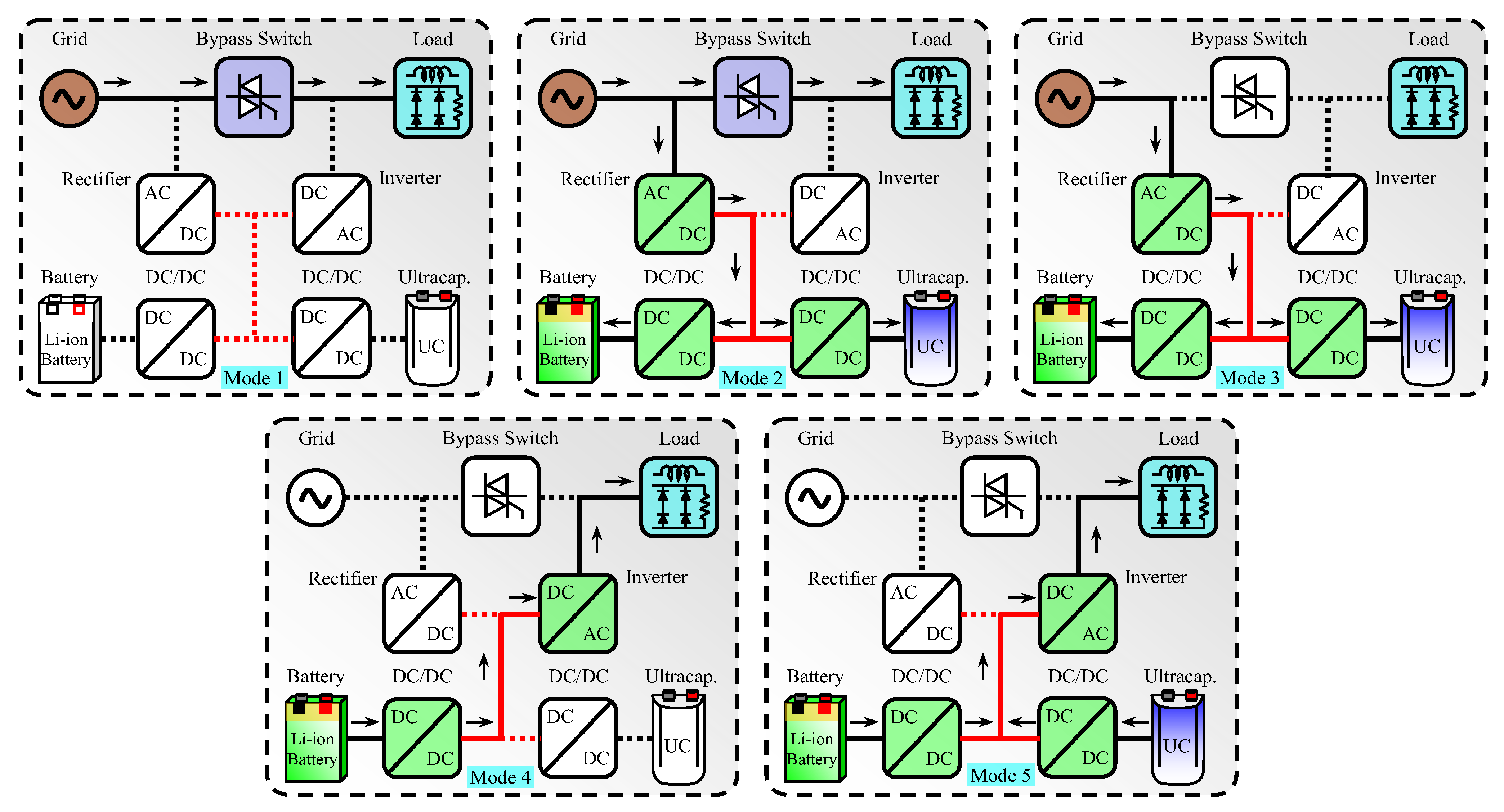
As shown in
Figure 6, the five operating modes defined by the proposed DEMA enable the hybrid UPS system to intelligently adapt to varying grid, load, and storage conditions. Through real-time monitoring of voltage, current, and SOC parameters, DEMA ensures smooth transitions between modes without power interruption or instability on the DC bus. Modes 1–3 guarantee optimal grid utilization and charging efficiency, whereas Modes 4 and 5 ensure reliable backup performance during outages. Particularly, Mode 5 highlights the system’s innovation by combining the fast dynamic response of the ultracapacitor with the long-term energy capability of the battery. These operational behaviors are experimentally verified in the next section, confirming the proposed algorithm’s stability, responsiveness, and superior transient performance under different load scenarios.
4. Experimental Studies and Results
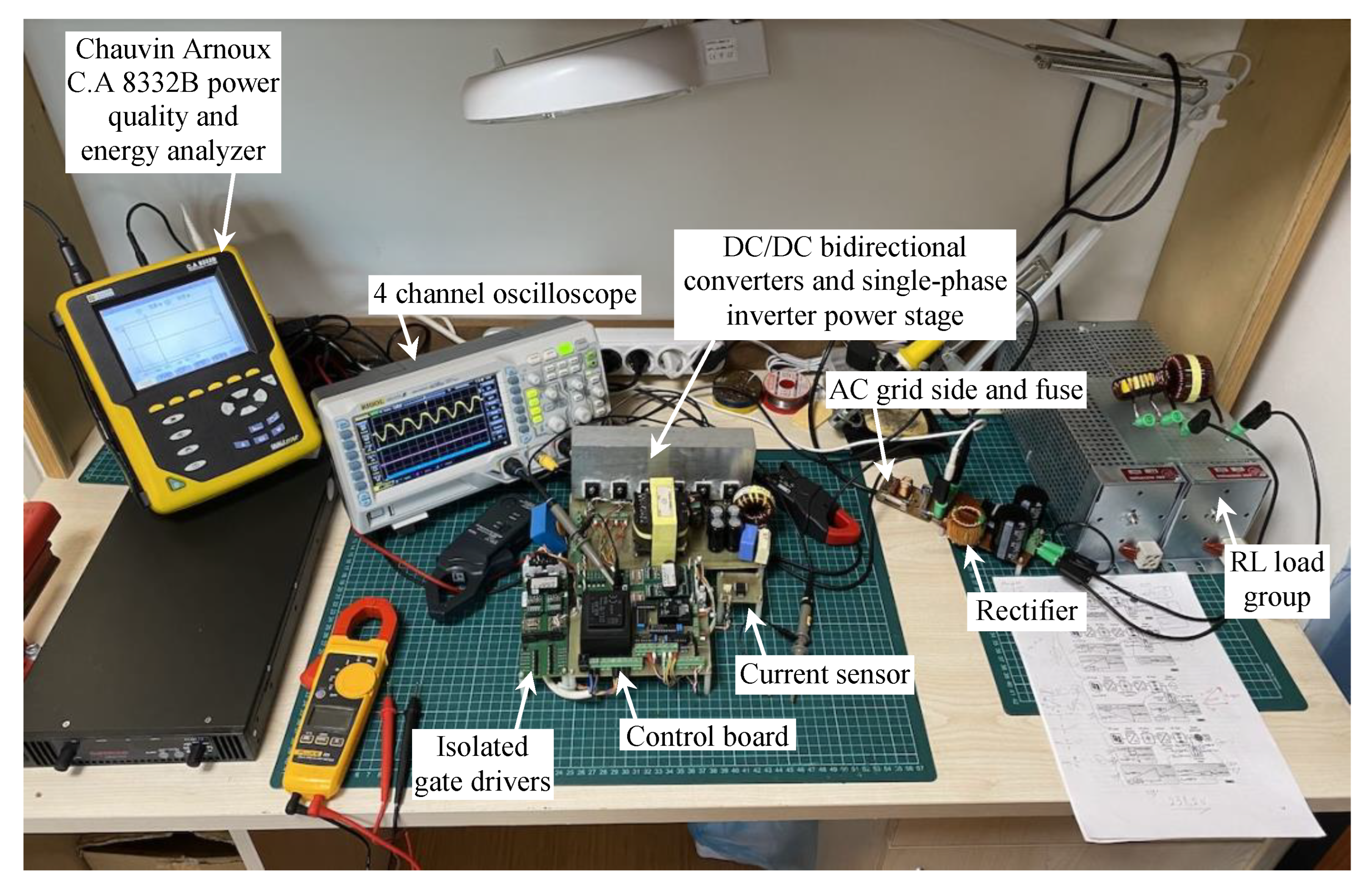
To validate the performance of the proposed DEMA and verify the behavior of the hybrid UPS system under real operating conditions, a comprehensive experimental setup was established in the laboratory. The configuration replicates the full-scale hybrid UPS structure, comprising the inverter stage, bidirectional DC/DC converters, battery and ultracapacitor units, and associated control circuitry. As illustrated in
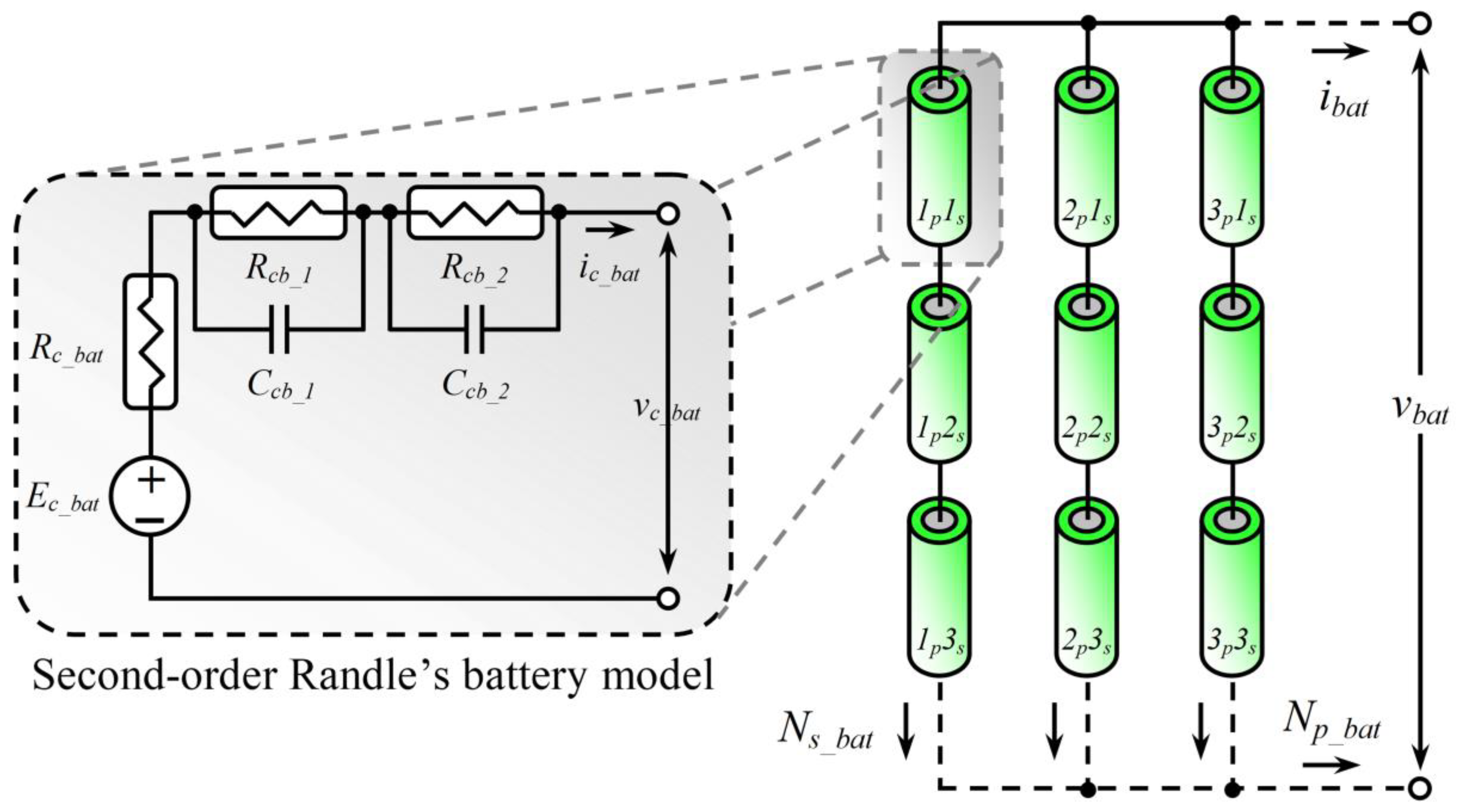
Figure 7, the hybrid energy storage system incorporates a Maxwell 5.8 F 160 V (BMOD0006 E160 B02), Maxwell Technologies Korea Co., Ltd., Gyeonggi-do, Republic of Korea, ultracapacitor module and a Tattu 22.2 V 6S 10 Ah lithium-ion battery pack, with five battery modules connected in series to achieve the required DC bus voltage level. The nominal DC bus voltage was regulated at 155 V, while the grid side voltage was maintained at 110 V
RMS through the line interface.
The bidirectional DC/DC converters for both the battery and ultracapacitor stages were driven by PI-based control loops implemented in the DEMA framework to manage the charge and discharge transitions between operating modes. The inverter employed a full-bridge topology, utilizing IGBT switches controlled via PWM gating signals derived from the sinusoidal reference generator in the DEMA control layer. Voltage and current signals were measured using AMC1200 differential isolation amplifiers and ACS712 Hall-effect current sensors, ensuring precise and isolated acquisition of the experimental data.
The inverter gate signals are generated using carrier-based sinusoidal PWM (SPWM) at a fixed switching frequency; the bidirectional DC/DC converters are likewise driven by fixed-frequency duty PWM under the PI control loops.
All experimental waveforms and performance metrics were recorded using a Chauvin Arnoux CA 8332B power quality and energy analyzer in conjunction with a Rigol DS1054Z digital oscilloscope. The detailed electrical and component parameters used in the experimental prototype are summarized in
Table 2.
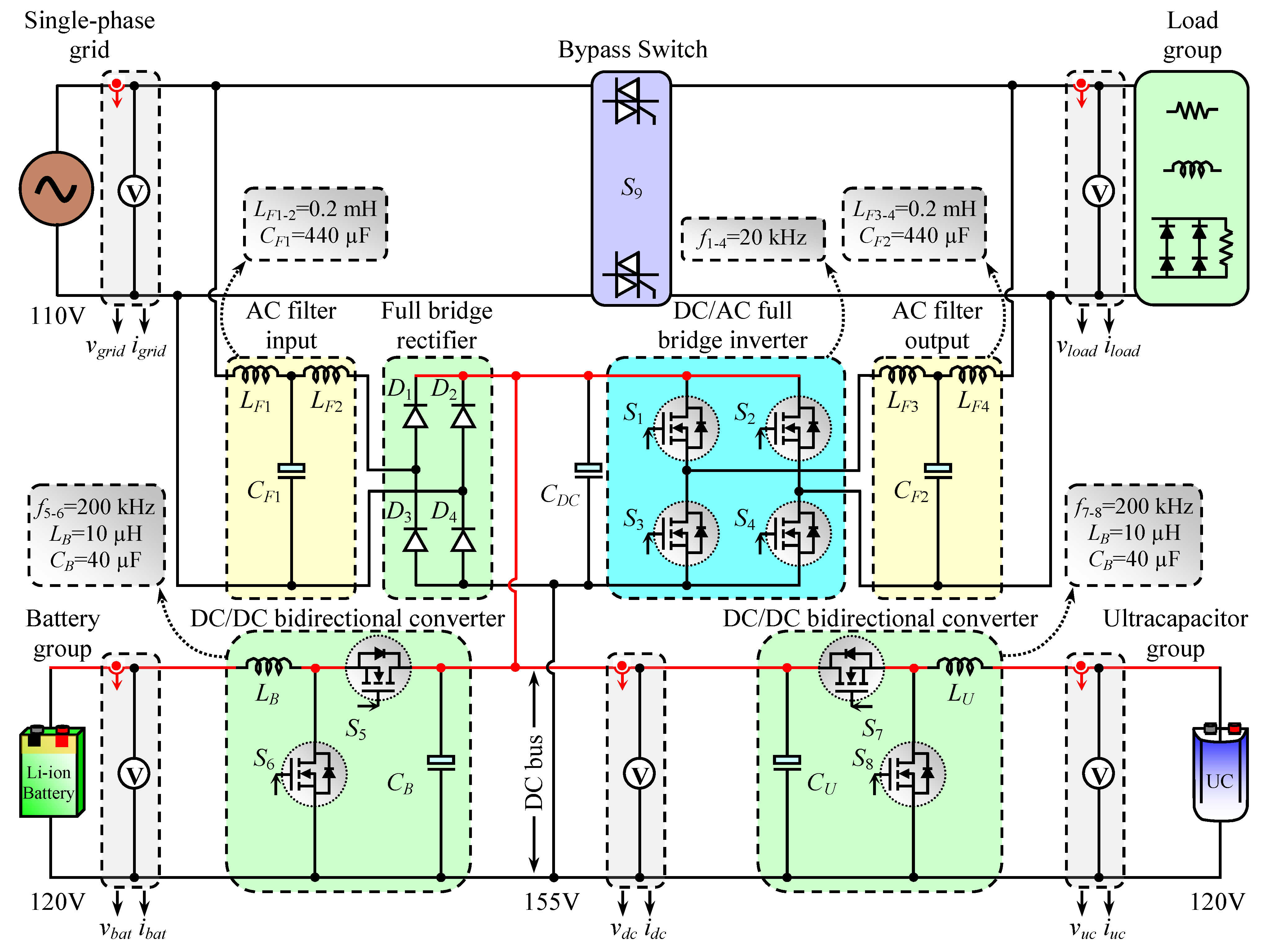
Figure 8 shows the experimental circuit diagram of the proposed hybrid UPS system. The experimental setup includes the grid source connected through a solid-state relay (SSR) switch to the load group. The grid passes through an LCL filter and a full-bridge rectifier, supplying the DC bus through a smoothing capacitor. The DC bus feeds a full-bridge inverter followed by another LCL filter at the AC output. The battery and ultracapacitor energy storage units are connected to the DC bus via bidirectional DC/DC converters, enabling bidirectional power flow. Voltage and current sensors are placed at the grid, DC bus, battery, and ultracapacitor nodes for real-time monitoring and control feedback.
Although five operating modes were defined in the proposed hybrid UPS system, only the critical ones were experimentally presented to demonstrate the operation and validity of the proposed DEMA. Mode 1 (grid supplying the load) and Mode 3 (grid charging the battery and ultracapacitor without load) were not explicitly included because their characteristics are already represented within Mode 2. In Mode 2, the grid supplies both the load and energy storage units, effectively encompassing the electrical and control dynamics of Modes 1 and Mode 3. Therefore, to avoid redundancy and emphasize the distinctive behavior of DEMA, only Mode 2 and the transition between Mode 4 and Mode 5 were experimentally validated.
Figure 9 depicts the experimental interconnections of the hybrid UPS prototype. The grid feeds the input LCL filter and full-bridge rectifier, charging the DC bus capacitor and DC bus. From the DC bus, the inverter supplies the load through an output LCL filter, while SSR S9 provides a grid–load bypass in grid-available conditions. The battery and ultracapacitor are connected to the DC bus via bidirectional DC/DC converters (buck for charging and boost for discharging). Voltage/current sensors at the grid, DC bus, battery, and UC feed the DEMA controller, which executes mode selection and issues PI-based PWM commands to the inverter and DC/DC power stages.
4.1. Mode 2—Experimental Results
In Mode 2, the hybrid UPS operates under grid-connected conditions where the grid not only supplies the load demand but also charges both the battery and ultracapacitor units simultaneously. During this operating mode, the bidirectional DC/DC converters of the storage units function in buck mode, transferring energy from the regulated DC bus (maintained at 155 V) to the battery and ultracapacitor. The DEMA maintains stable voltage regulation and ensures balanced charging of both storage devices by continuously monitoring the voltage and current feedback signals. This mode demonstrates the coordination capability of the proposed algorithm during steady-state charging conditions while the load is supplied directly from the grid.
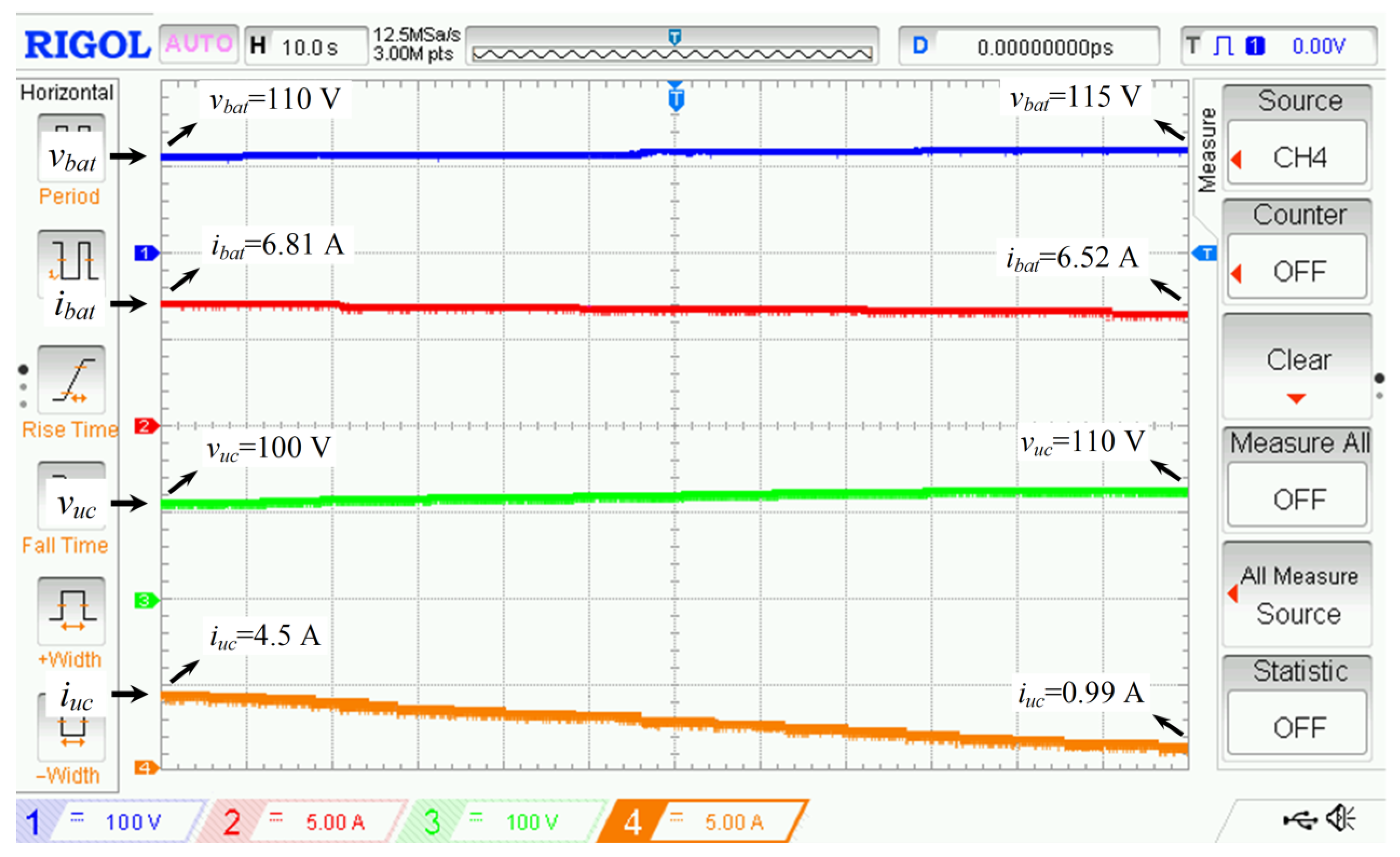
Figure 10 shows the oscilloscope waveforms of the battery voltage and current, as well as the ultracapacitor (UC) voltage and current, captured over a 100 s experimental interval. The battery voltage increased gradually from 110 V to 115 V, confirming the successful completion of the charging process. The battery current decreased slightly, from 6.81 A to 6.52 A, indicating smooth current control and a transition toward a fully charged state. The ultracapacitor voltage similarly increased from 100 V to 110 V, while its current decreased from 4.5 A to 0.99 A, consistent with a controlled charging behavior. These results verify that DEMA successfully maintains proper current distribution between the battery and UC during the grid-connected charging phase without overcurrent or instability.
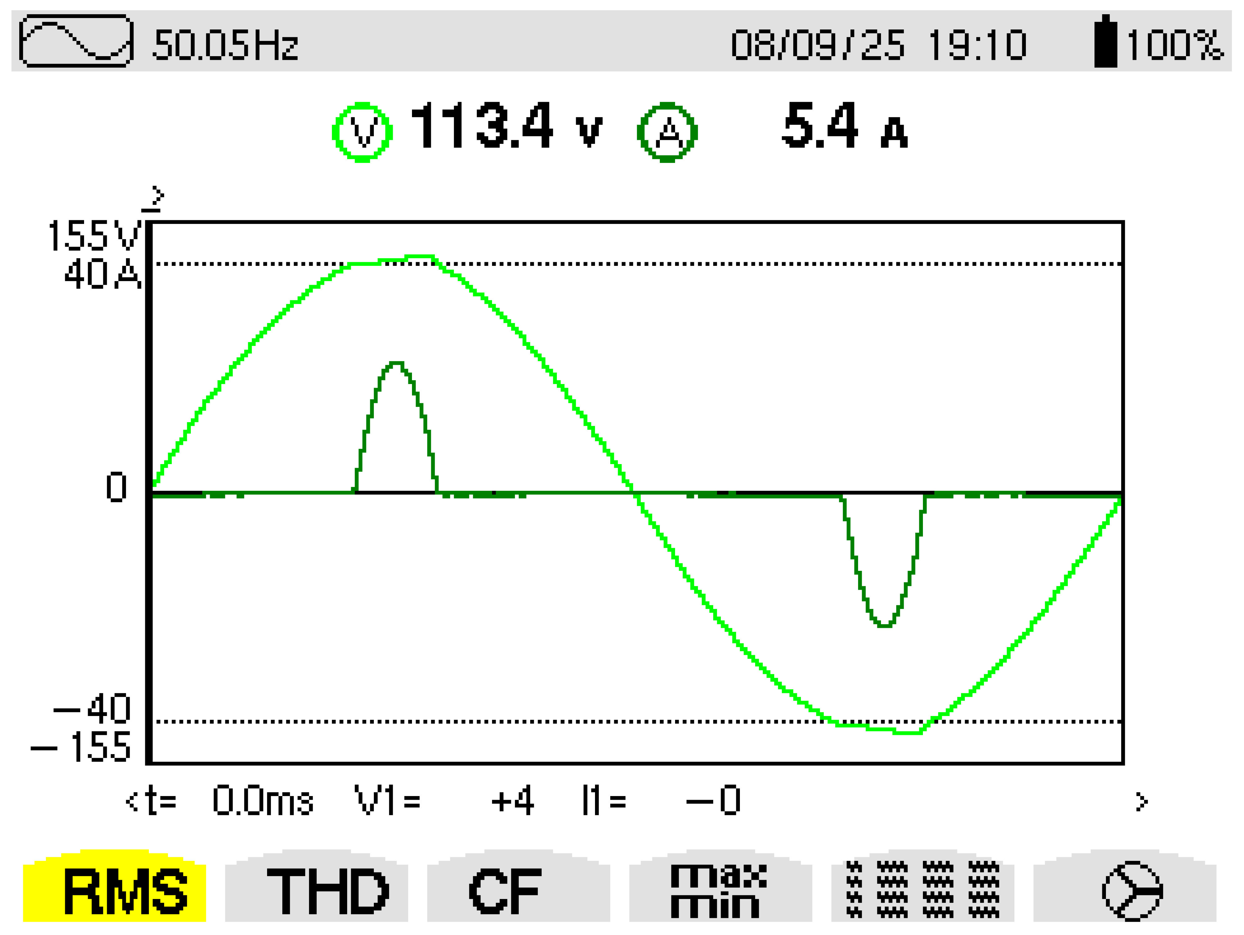
As shown in
Figure 11, the grid voltage and load current waveforms measured by the power quality and energy analyzer confirm stable grid-to-load power transfer. The grid voltage remained constant at 110 V
RMS, while the load current was measured as 5.4 A
RMS, corresponding to a single-phase diode rectifier load. These experimental results validate the correct operation of Mode 2, demonstrating that the proposed system can manage simultaneous load supply and coordinated charging of both energy storage units under grid-connected operation with high stability and power quality.
4.2. Mode 4 and Mode 5—Experimental Results
In this section, the experimental results demonstrating the dynamic transition between Mode 4 and Mode 5 are presented to validate the effectiveness of the proposed DEMA. During Mode 4, the hybrid UPS system operates under grid-off conditions, where the battery alone supplies the load demand. When a sudden increase in load occurs, the algorithm detects the transient event and activates the ultracapacitor in Mode 5 to support the battery and stabilize the DC bus voltage. This operating scenario highlights the unique contribution of the proposed control strategy, where the UC assists the battery during high-power transients, thereby reducing the battery’s current stress and preventing deep discharge that would otherwise accelerate degradation and reduce the battery’s lifetime.
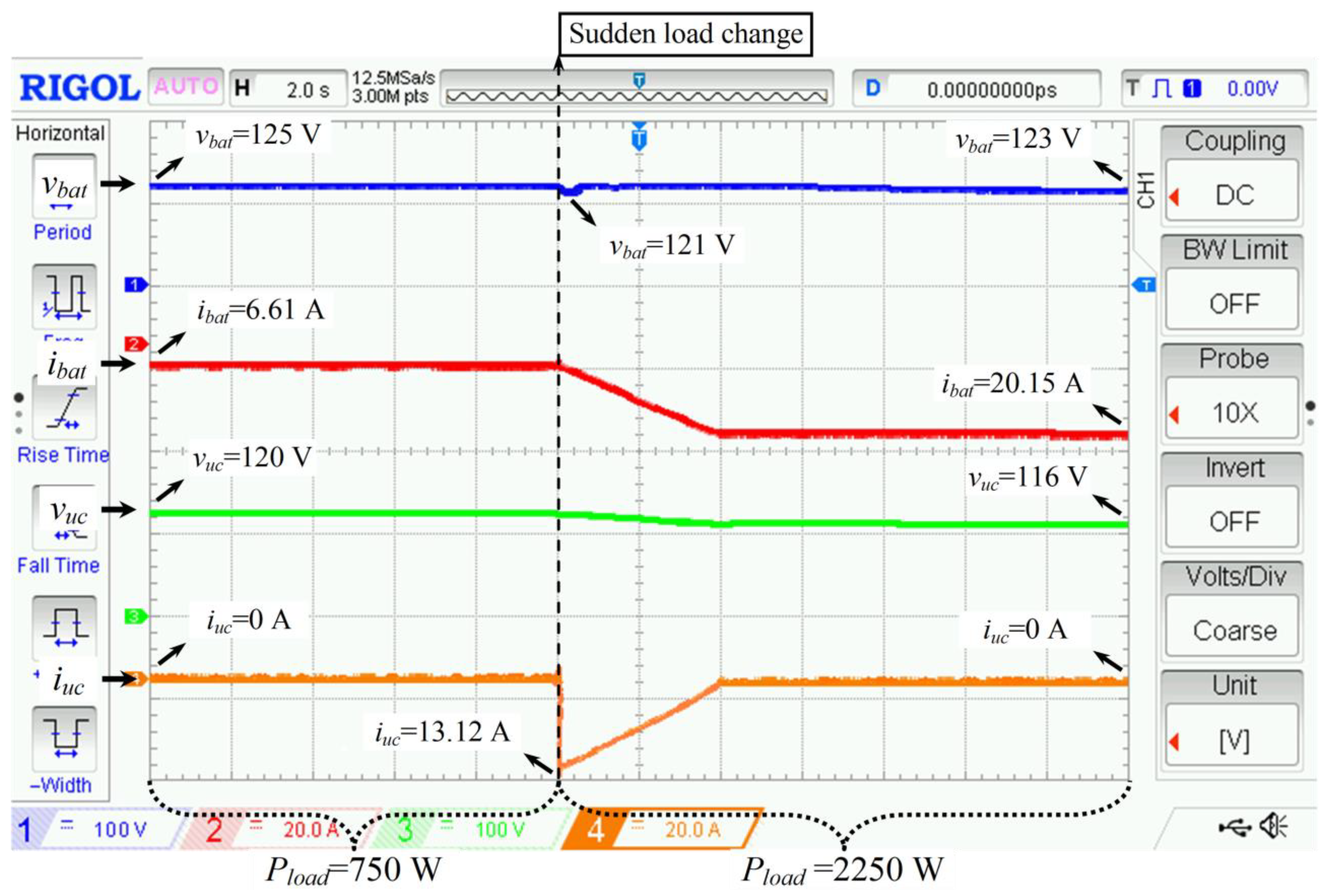
Figure 12 presents the oscilloscope waveforms of the battery voltage and current, as well as the UC voltage and current, recorded over a 20 s period. Initially, in Mode 4, the load power is 750 W, and only the battery discharges to supply the load. At
t = 8 s, an additional 1500 W load is suddenly applied, increasing the total load power to 2250 W, which triggers the transition to Mode 5. The battery voltage slightly drops from 125 V to 121 V during this transient but quickly recovers to 123 V, demonstrating the algorithm’s fast dynamic regulation. The battery current initially measures 6.61 A and smoothly ramps up to 20.15 A within approximately 4 s, avoiding abrupt current surges. The UC voltage decreases modestly from 120 V to 116 V, while its current rises sharply from 0 A to 13.12 A at the moment of load engagement. This rapid UC current response confirms that the proposed algorithm successfully detects the transient and commands the UC to inject power instantaneously. Consequently, the UC delivers the additional power required by the load during the transient, preventing excessive current draw from the battery. After stabilization, the UC current returns to 0 A, while the battery continues to discharge steadily. These results clearly verify the superior dynamic response of the proposed control structure and demonstrate how the UC effectively mitigates transient stress on the battery, thus extending its operational lifetime.
To emphasize the importance of the UC in this process,
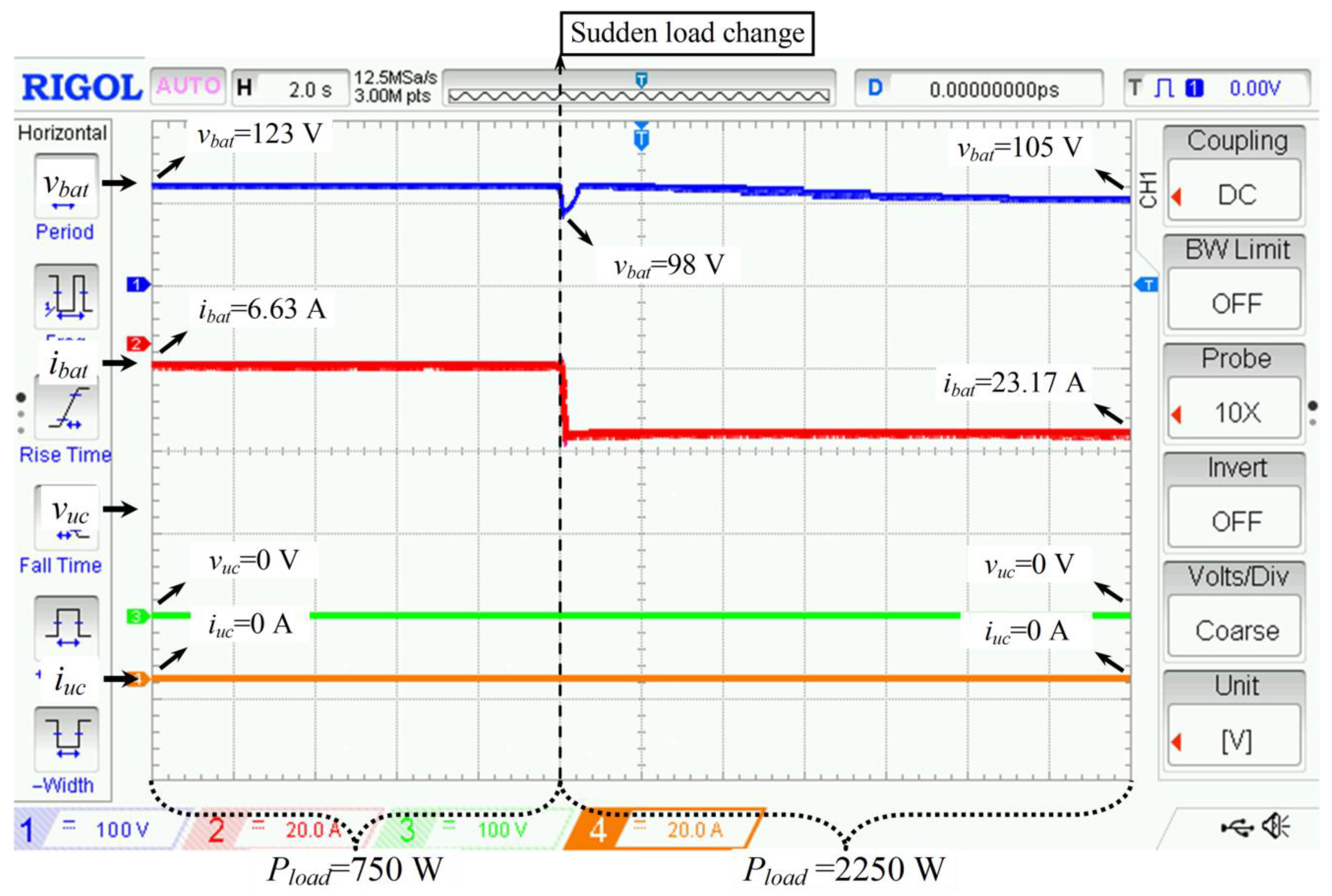
Figure 13 illustrates the experimental results obtained when the UC is intentionally deactivated. In this case, the system operates solely with the battery under identical load conditions. Initially, the system operates in Mode 4 at 750 W, and at
t = 8 s, the same additional 1500 W load is applied, resulting in a total load of 2250 W. The absence of the UC leads to a pronounced voltage collapse during the transition. The battery voltage drops from 123 V to 98 V and then slowly recovers to 105 V, showing a significantly larger transient deviation and longer recovery time compared to the case with active UC support.
The battery current sharply increases from 6.63 A to 23.17 A almost instantaneously at the moment of load application, confirming the lack of transient buffering. This sharp current surge indicates a deep discharge event, which would accelerate capacity fading and reduce battery cycle life under repeated transients. Thus,
Figure 13 experimentally validates the crucial role of the UC in the proposed hybrid configuration, proving that its absence directly increases the electrical and thermal stress on the battery during sudden load disturbances.
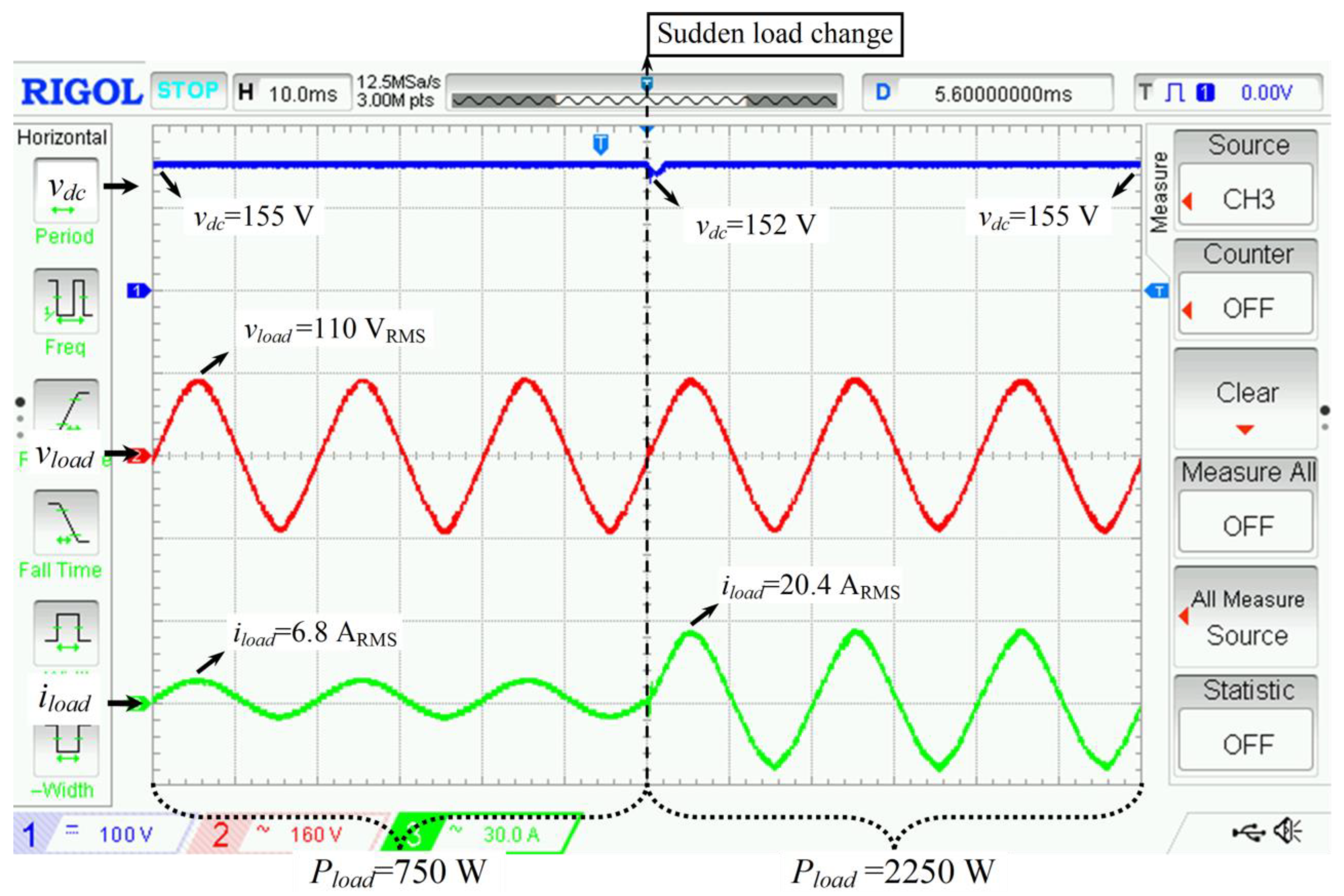
Figure 14 shows the oscilloscope waveforms of the DC bus voltage, grid voltage, and load current for the case where the UC is active. The measurements were captured with a time base of 10 ms/div to clearly illustrate the AC-side waveform characteristics. The DC bus voltage remains highly stable throughout the experiment, maintaining a nominal value of 155 V, with only a minor dip to 152 V during the transient event. The recovery to 155 V occurs within approximately 4 ms, demonstrating excellent voltage regulation. The grid voltage remains constant at 110 V
RMS, while the load current increases from 6.8 A to 20.4 A after the load step. Although a slight voltage disturbance appears during the transient, it remains within a few volts and does not affect load continuity or waveform quality. These results confirm that the DEMA maintains stable DC bus and AC output characteristics, even during severe load transitions.
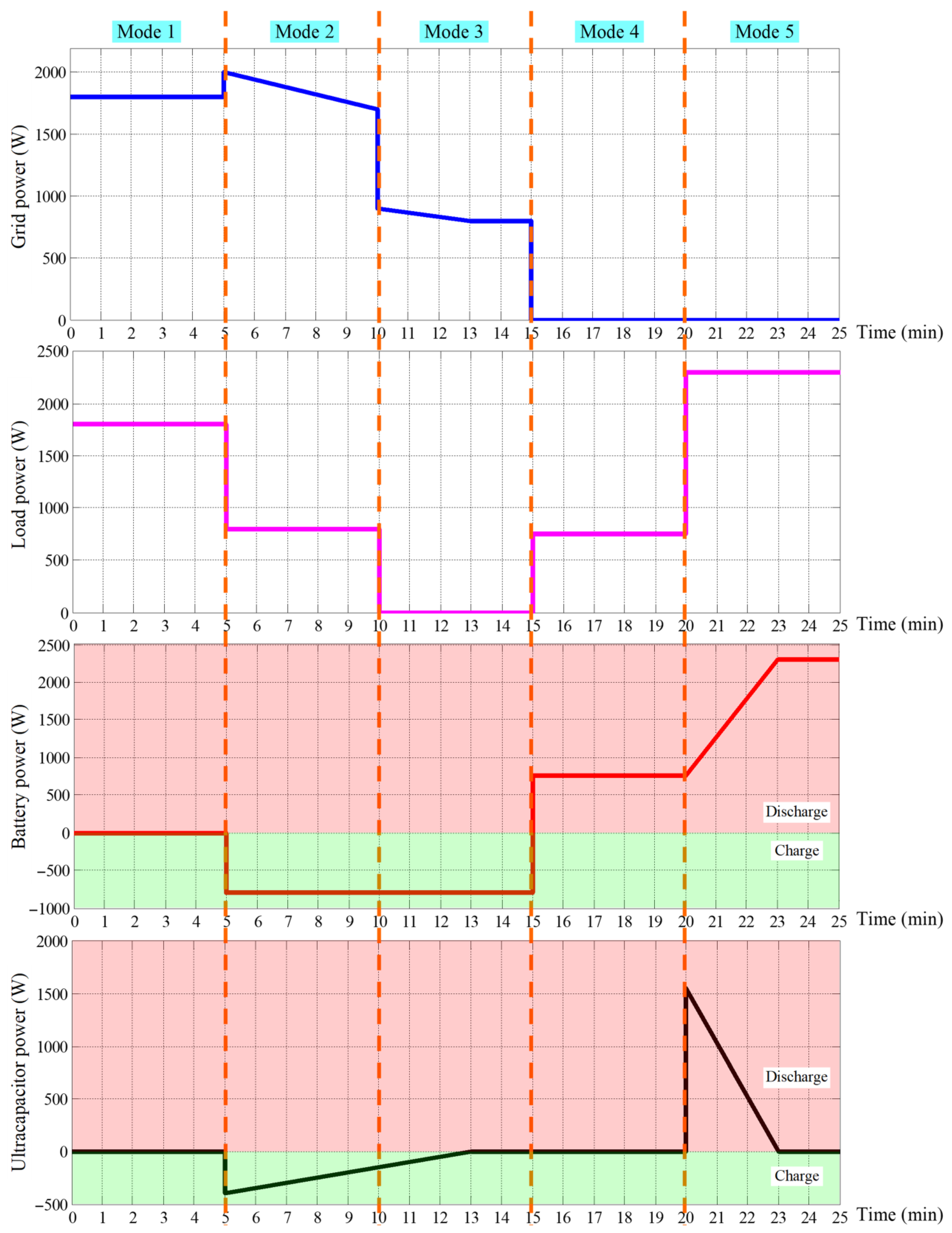
Figure 15 presents the experimentally recorded power profiles of the grid, load, battery, and ultracapacitor as functions of time, illustrating the transitions across all five operating modes. The figure provides a comprehensive view of the system’s power flow evolution—from grid-supplied operation (Mode 1) to the hybrid discharge condition (Mode 5). It clearly demonstrates how the proposed DEMA regulates energy sharing among the components under varying operating states. The smooth transitions and consistent power balance observed in the plots confirm the algorithm’s accuracy, stability, and dynamic adaptability across different load and grid conditions.
Overall, the experimental results from
Figure 12,
Figure 13 and
Figure 14 conclusively validate the effectiveness of the proposed dynamic energy management algorithm. When the ultracapacitor is active, the hybrid system achieves superior transient stability, minimal DC bus voltage deviation, and significantly reduced battery current overshoot. In contrast, the absence of the UC results in higher battery current spikes and greater voltage drops. Hence, the coordinated control between the battery and UC, as managed by DEMA, ensures robust transient performance and improved energy-sharing efficiency, demonstrating the core innovation and practicality of the proposed hybrid UPS architecture.
As presented in
Table 3, the proposed hybrid UPS system exhibited remarkable improvements compared with a conventional battery-only control approach. The DC bus voltage overshoot was reduced from 19.8% to approximately 2%, and the battery current ripple decreased by 30–40%, validating the effectiveness of the DEMA in maintaining stable operation. The reduction in battery current ripple was determined by comparing the peak-to-peak amplitudes of the battery current waveforms in
Figure 12 and
Figure 13. The analysis clearly shows that activating the ultracapacitor smooths the transient response and significantly mitigates instantaneous current stress on the battery. Additionally, the mode transition response time improved from 10 ms to below 4 ms, highlighting the superior transient performance and dynamic stability of the proposed hybrid algorithm.
Table 4 presents key parameters, including voltage and current values for the battery, ultracapacitor, load, and DC bus voltage, of the proposed system. To specifically quantify the system’s transient performance, the response time during the transition from Mode 4 (battery-only operation) to Mode 5 (battery–ultracapacitor hybrid support) was measured as 4 ms. This rapid response demonstrates the efficiency of the proposed dynamic energy management algorithm in detecting load transients and activating the ultracapacitor module instantaneously to stabilize the DC bus voltage and protect the battery from deep discharge.
The proposed study contributes to the literature by addressing performance parameters that are rarely analyzed together in hybrid UPS systems—namely, DC bus voltage deviation, battery current ripple, and mode transition dynamics. While existing hybrid energy storage or UPS studies typically report DC bus voltage overshoots between 3% and 7% [
36,
37,
38], the experimental results of this work demonstrate a significantly lower deviation of only 1–2% during sudden load transitions. Furthermore, the proposed DEMA effectively limits the battery current ripple by 30–40%, minimizing current stress and extending battery lifetime.
Table 4 presents a comparative summary between representative studies in the literature and the results obtained in this work, highlighting the superior transient stability, smooth mode transition, and enhanced voltage regulation performance achieved by the proposed control approach.
Table 5 presents the experimentally measured efficiencies of the inverter and the bidirectional DC/DC converters for both the battery and ultracapacitor units under key operating modes (Modes 2, Mode 4, and Mode 5). The experimental results demonstrate that, under steady-state operation, the battery-side DC/DC converter achieved an efficiency of 94.8%, and the ultracapacitor-side converter achieved an efficiency of 95.2% in Mode 2. During Mode 5 (battery–UC cooperative discharge), the inverter efficiency reached 95.7%, while the DC/DC converter efficiencies were 95.9% (on the battery side) and 94.7% (on the UC side). All efficiency values were obtained through direct power measurements using a Chauvin Arnoux C.A 8332B (Chauvin Arnoux Metrix LTD, Velaux, France) power and energy analyzer and Rigol DS1054Z digital oscilloscope (Rigol Technologies, Inc., Portland, OR, USA).
To quantitatively evaluate the effect of the proposed control strategy on battery longevity, a stress-based life estimation approach was considered. According to empirical models that relate battery capacity fade to Ah-throughput and current amplitude [
39,
40], a 30–40% reduction in current ripple and approximately 35% decrease in transient peak current achieved by DEMA correspond to a projected increase of 20–25% in effective cycle life. This improvement highlights the capability of the proposed algorithm to reduce electrochemical stress and thermal loading on the battery during dynamic load transitions.
Figure 15 shows the power graphs of the grid, load, battery, and ultracapacitor for all five operating modes, enabling the clear identification of mode entries/exits under the proposed DEMA. The plots highlight coordinated power sharing—battery-only supply in Mode 4 and UC-assisted peak support in Mode 5—while confirming stable transitions and consistent power balance across modes.
The present prototype is single-phase and lab-scale, with fixed-gain PI controllers and a fixed UC engagement threshold tuned to the tested hardware. Thermal effects and UC parameter drift are only partially modeled, and endurance beyond repeated daily trials was not assessed over long durations. These constraints may influence performance at higher ratings, in different environments, or with broader load spectra.
4.3. Uncertainty and Repeatability
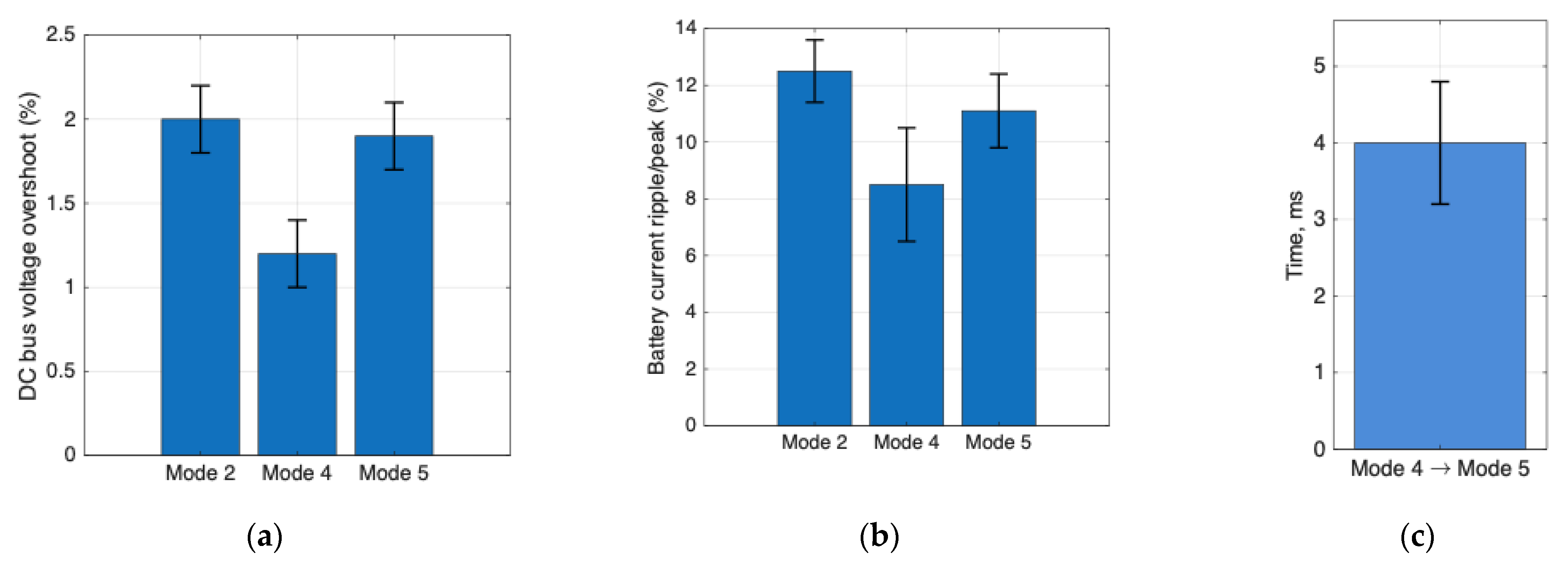
All reported metrics were obtained from five repeated trials per operating mode under identical load, ambient, and controller settings. We present values as mean ± standard deviation and include 95% confidence intervals (CI = 1.96·σ/√N). Power quantities were measured using a Chauvin Arnoux C.A 8332B analyzer; voltage/current and peak-to-peak ripple were acquired from a Rigol DS1054Z oscilloscope. Efficiency uncertainty was computed via error propagation for
:
DC-bus overshoot and battery current ripple statistics were derived from the oscilloscope traces over identical time windows across trials.
Figure 16 indicates that DC-bus overshoot remains consistently below ~2% with low dispersion across all modes, evidencing robust voltage regulation. It also shows that battery current ripple is highest in Mode 4 (battery-only) and markedly reduced in Mode 5 due to UC assistance, while the transition from Mode 4 to Mode 5 settles in ~4 ms with tight variability.
5. Conclusions
This paper presents the design, implementation, and experimental validation of a DEMA for a hybrid UPS system that integrates battery and ultracapacitor storage units. The proposed control strategy dynamically coordinates energy sharing among the storage components based on real-time grid status, load demand, and battery state of charge. Experimental results demonstrated that the algorithm effectively minimizes DC bus voltage deviations to below 2% and reduces battery current ripple by 30–40%, ensuring smooth and stable operation during sudden load transitions. Furthermore, the experimental and analytical evaluations confirmed that the proposed DEMA significantly mitigates transient current stress and ripple effects, resulting in an estimated 20–25% improvement in the battery’s effective cycle life by reducing both electrochemical and thermal degradation during dynamic load transitions.
The transition from Mode 4 to Mode 5 verified the algorithm’s capability to detect transient events and instantaneously activate the ultracapacitor, preventing deep battery discharge and extending its lifetime. In comparison with conventional hybrid control schemes, the proposed approach achieved faster response, superior voltage regulation, and enhanced system reliability. The comparative analysis confirmed that the DEMA provides a robust and scalable solution for future battery-ultracapacitor-based UPS and energy storage systems.
Future work will focus on extending the algorithm for real-time digital controller implementation and exploring multi-modular configurations for higher-power industrial UPS applications, further improving energy efficiency and operational resilience. Future research will focus on incorporating temperature-dependent modeling of ultracapacitor parameters to further enhance the robustness and adaptability of the proposed DEMA under varying environmental and thermal conditions. The proposed DEMA is inherently scalable: for higher power ratings, hardware elements (power stage, LCL filters, DC-bus capacity, and sensing) are resized, and PI controllers are reidentified, while decision thresholds are expressed in per-unit terms of the new rating. Future work will validate this scaling on ≥10 kW interleaved converter prototypes. AI/ML augmentation—encompassing data-driven SOC/SOH estimation, short-horizon load prediction, and safety-bounded gain scheduling—can further mitigate DC-bus voltage fluctuations and battery stress while retaining DEMA control authority.
Scaling to multi-kilowatt, multi-module UPS will require power-stage resizing, UC interleaving, and re-identification of PI gains with per-unit thresholds. Adaptive/AI-assisted tuning (model-aware gain scheduling, short-horizon load prediction, SOH-aware limits) can further reduce DC-bus excursions and battery stress. Extended soak tests and field evaluations in data-center/hospital-grade loads will complete the path to deployment.
