Abstract
Radial drilling technology, which involves drilling multiple micro-horizontal wellbores radially from a main wellbore, can effectively expand the contact area between the wellbore and the reservoir, as well as the swept volume of thermal fluid. It is a promising technology for enhancing the efficiency of heavy oil thermal recovery. However, a systematic numerical simulation study on the application of this technology in the cyclic steam stimulation (CSS) development of heavy oil reservoirs is currently lacking. This paper establishes a numerical thermal recovery model for heavy oil reservoirs based on an unstructured grid modeling method, which can accurately describe the complex geometry of multi-layer, multi-branch radial wells. The model is discretized using the finite volume method and solved with a fully implicit method. Then, based on the geological parameters of a typical heavy oil reservoir, a comparative study was conducted on the production dynamics and physical field evolution of horizontal wells, single-layer radial wells, and dual-layer radial wells during the CSS process. The results indicate that, compared to conventional well types, dual-layer multi-branch radial wells can simultaneously inject steam into the upper and lower parts of the reservoir. This forms a more balanced and extensive three-dimensional heated body, significantly improving the planar sweep efficiency of heat and the uniformity of reserve recovery, thereby substantially increasing crude oil production and recovery factor. Compared to the horizontal well scenario, using dual-layer radial wells for CSS can increase cumulative oil production by 44.8%.
1. Introduction
Heavy oil resources hold a significant position in global fossil energy reserves. However, their physical characteristics of high viscosity and poor fluidity make conventional cold production methods economically unviable [1,2]. Therefore, thermal recovery technologies, represented by steam injection, are the primary means for heavy oil extraction. Among them, cyclic steam stimulation (CSS) is widely used in pilot tests and commercial development of various heavy oil reservoirs due to its mature technology and low investment [3,4,5].
Traditional CSS primarily relies on vertical wells. Its core mechanism involves injecting high-temperature steam into the wellbore to heat the crude oil in the near-wellbore zone, thereby significantly reducing its viscosity for production. However, vertical wells have prominent limitations: the heating range of steam is confined to a small cylindrical area around the well, leading to low thermal efficiency, rapid production decline, and a low ultimate recovery factor [6,7,8]. To address this issue, horizontal well technology was introduced into the field of heavy oil thermal recovery. With their extensive wellbore-reservoir contact section, horizontal wells significantly expand the steam sweep volume and the crude oil drainage area, and their development performance is generally superior to that of vertical wells [9,10,11]. Nevertheless, the steam sweep volume of conventional horizontal wells is still primarily limited to a narrow elongated area on both sides of the wellbore, making it difficult to achieve uniform and efficient heating of the entire drainage area, which restricts the further realization of their production enhancement potential [12]. Meanwhile, the phenomenon of steam gravity override persists, where heat preferentially migrates upwards, further reducing heat utilization efficiency and affecting the uniformity of reserve recovery [13,14,15].
How to further expand the swept volume of thermal fluids and improve the uniformity of planar recovery has become a key technical challenge that urgently needs to be solved in the field of heavy oil thermal recovery. Radial drilling technology offers a promising solution. This technology uses hydraulic jetting or a micro-drilling bit to drill multiple micro-horizontal wellbores (i.e., laterals) in different directions from a predetermined depth in a single vertical wellbore, forming a radial well network system underground [16,17]. This technology has advantages such as relatively low operational costs, minimal reservoir damage, and the flexibility to stimulate multiple zones. It has been successfully applied in fields like low-permeability oil and gas reservoirs and coalbed methane, where its superior production enhancement effects have been confirmed [18,19]. This technological concept is extended to the field of heavy oil thermal recovery with the proposal of using multi-layer radial wells for CSS. It is anticipated that by simultaneously injecting thermal fluids into the upper and lower parts of the reservoir, a three-dimensional heating network can be constructed, thereby fundamentally improving the uniformity of heat distribution.
The core advantage of radial well technology lies in its ability to flexibly drill multi-branch wellbores with arbitrary numbers and azimuths, forming a complex three-dimensional well network underground. However, this complex spatial structure also poses a significant challenge for numerical simulation [20,21]. In fact, numerical simulation has been widely promoted and used for EOR in heavy oil reservoirs [22,23]. Due to its ability to clearly reveal complex thermo-hydro processes and efficiently evaluate the long-term effects of different development strategies, it has become an essential tool for mechanistic studies, parameter optimization, and design of thermal processes such as steam stimulation [24,25]. Currently, major commercial thermal recovery simulation software, such as CMG-STARS, mostly uses structured or locally refined grids, which struggle to accurately represent the arbitrary geometry of branch wellbores and the complex wellbore-reservoir connection relationships. This prevents accurate simulation of the radial well thermal recovery process [26,27,28]. To this end, a non-isothermal thermal recovery numerical simulation model that couples multiphase flow, heat conduction, and convection has been independently developed in this study. Combined with Perpendicular Bisector (PEBI) unstructured grid technology, it can achieve precise geometric partitioning and discretization for complex radial well systems with any branch angle and number [29,30]. Based on this, by comparing the development effects with conventional vertical wells, while the current implementation is serial, the underlying FVM method and PETSc solver framework are found to be inherently parallelizable single-layer horizontal wells, and the temperature field evolution and production enhancement mechanisms of multi-layer radial wells during the CSS process are systematically revealed. The aim is to provide theoretical guidance for the optimal design and field application of this technology in heavy oil reservoirs.
2. Methodology
2.1. Mathematical Model
This research is conducted based on an independently developed non-isothermal, multiphase flow numerical simulator. The model considers three main components in the reservoir: water, non-volatile heavy oil, and rock. The fluids exist in three phases: Aqueous (A), Gaseous (G), and Oleic (O).
2.1.1. Mass Conservation Equations
The mass conservation equation for the water component can be expressed as:
where t is time; ϕ is porosity; SA and SG are the saturations of the aqueous and gaseous phases, respectively; ρA and ρG are the densities of the aqueous and gaseous phases; and are the mass fractions of the water component in the aqueous and gaseous phases; and are the mass flow velocities of the aqueous and gaseous phases; qA and qG are the mass flow rates per unit volume for the aqueous and gaseous phases in production or injection wells.
The oil component exists in the oil phase. Considering the convective phase and the source/sink phase, the equation is:
where is the concentration of the oil component in the oil phase; is the oil saturation; is the oil phase density; is the oil phase mass flow velocity; qO is the mass flow rate per unit volume for the oil phase in production or injection wells.
2.1.2. Energy Conservation Equation
Considering the effects of heat conduction within the reservoir, heat convection due to fluid flow, heat from chemical reactions, and heat changes associated with fluid injection or production, the energy conservation equation can be expressed as:
where ρR is the rock density; UR, UA, UG, UO are the specific internal energies of the rock, aqueous phase, gaseous phase, and oil phase, respectively; T is the temperature; HA, HG, HO are the specific enthalpies of the aqueous, gaseous, and oil phases; λeff is the effective thermal conductivity.
2.1.3. Equations of State
Changes in pressure and temperature can both cause rock deformation, leading to changes in porosity, which can be expressed as:
where is the reference porosity at initial pressure and initial temperature , is the rock compressibility, and is the rock thermal expansion coefficient.
The density and viscosity-temperature relationships of crude oil can be user-defined. The equations of state for water and steam are more complex; this study primarily calculates properties such as density, internal energy, enthalpy, and viscosity for water and steam based on the IAPWS-97 standard [31].
2.1.4. Boundary Conditions
There are mainly two types of boundary conditions: Dirichlet and Neumann. For the outer boundary condition, a closed boundary condition, which is a Neumann boundary condition commonly used in commercial software, is adopted.
The inner boundary can be a constant pressure or constant flow rate boundary. According to the classic Peaceman equation [32], the mass flow rate of a mobile phase β in the grid containing the source/sink can be obtained as:
where qβ is the mass flow rate of the mobile phase β in the source/sink grid; ρβ is its density; μβ is its viscosity; pβ is its pressure in the grid; pwb is the wellbore bottom-hole pressure in the grid; PI is the productivity index. The PI calculation follows the conventional Peaceman model concept but is adapted for the PEBI unstructured grid’s equivalent radius . Specifically, we used the area-equivalent method, , where A is the area of the PEBI cell.
2.2. Model Solution
The primary governing equations for the model are the mass conservation Equations (1) and (2), and the energy conservation Equation (3). However, the primary variables for the solution change with the phase state. When no steam is present, the primary variables are pressure P, temperature T, and aqueous phase saturation Sw. When a phase change occurs and steam is generated, the temperature and pressure satisfy the saturated steam pressure curve, and the primary variables become pressure P, aqueous phase saturation Sw, and gaseous phase saturation Sg.
To clarify the numerical handling, the model employs a standard fully implicit Newton-Raphson method, not a predictor-corrector strategy. When phase change occurs and variables are switched, Temperature is recalculated as a secondary variable from the saturation curve based on pressure. We found this method to be sufficiently robust that a specific timestep stepback mechanism upon phase appearance was not required; the automatic timestepping strategy was sufficient to ensure convergence. The model is discretized using the finite volume method. The solution framework is implemented using the open-source PETSc (Portable, Extensible Toolkit for Scientific Computation) library. For the outer non-linear Newton iterations, the convergence tolerance was set to 1.0 × 10⁻⁵ with a maximum of 9 iterations. The inner linear system at each Newton step is solved using the GMRES method with an ILU(0) preconditioner, adopting the default PETSc settings.
2.3. Model Validation
To verify the correctness of the mathematical model established in this paper, a vertical well CSS model was created. The model dimensions are 110 m × 110 m × 15 m, with a grid of 21 × 21 × 7. The top of the model is at a depth of 600m, with a net-to-gross ratio of 0.7, porosity of 0.2, and permeability of 1.5 × 10⁻⁹ m2. The initial pressure is 6 MPa, the temperature is 38 °C, the initial crude oil viscosity at reservoir temperature is 2000 mPa·s, and the initial oil saturation is 0.75. A central vertical well, which perforates the entire reservoir, is used for CSS. During the steam injection phase, the injection rate is 120 m3/d, the injection temperature is 270 °C, and the steam quality is 0.55. Each cycle consists of 12 days of steam injection, 4 days of soaking, and 120 days of production. A total of 6 cycles were simulated.
To validate the effectiveness of the model, the simulation results were compared with those obtained from the commercial software CMG 2021, as shown in Figure 1. The figure shows that the initial production rate is high after the soaking period and then declines rapidly. Due to the continuous production of crude oil from the near-wellbore region, the peak production rate of each cycle gradually decreases. To quantitatively assess the matching accuracy, we calculated the Root Mean Square Error (RMSE). This was computed by creating a unified time axis of all output steps from both models over the entire simulation period (0–820 days, 434 total points) and using linear interpolation. The calculation shows an RMSE of 0.26 m3/d for the daily oil rate (Figure 1a), which is a low relative error of ~1.04% of the peak production range (~25 m3/d). The RMSE for the daily water rate (Figure 1b) is 0.80 m3/d, representing a relative error of ~1.00% of its peak range (~80 m3/d). Both low relative errors quantitatively confirm the high consistency between our model and the CMG software.
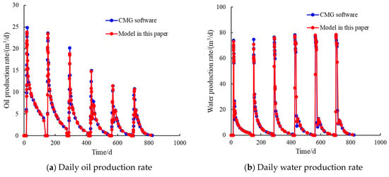
Figure 1.
Comparison of production curves.
3. Case Study
3.1. Numerical Simulation Model Establishment
To study the effectiveness of different well types in developing heavy oil reservoirs, numerical simulation models were established for a horizontal well (Case 1), a single-layer 8-branch radial well (Case 2), and a dual-layer 16-branch radial well (Case 3) for CSS development. The 8-branch configuration was chosen as the representative example for the single-layer radial well (Case 2) based on the premise that a larger number of branches generally provides a greater wellbore-reservoir contact area and a wider heat sweep volume. This configuration is thus considered sufficient for a mechanistic comparison against the conventional horizontal well (Case 1) to demonstrate the superiority of the radial well design. The planar dimensions of the model are 300 m × 300 m. In the horizontal well scenario, the length of the horizontal section is 200 m, and the length of a single radial branch is 100 m.
Due to the varying angles of the branch wells, conventional Cartesian or corner-point grids are difficult to use for effective meshing of models containing radial wells, and grid cell cutting can easily occur, leading to non-convergence. Therefore, this study employs PEBI unstructured grids for simulation. This method allows for a static, local refinement to be applied a priori—specifically, within a 10 m radius of the wellbores (horizontal and radial)—to accurately capture near-wellbore physics while minimizing the total cell count. The planar grid discretization results for the horizontal well and radial well scenarios are shown in Figure 2.
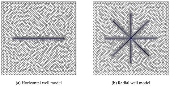
Figure 2.
Planar grid discretization (blue represents wellbore grids).
Based on the planar grid, a 2.5D model was established. The model is vertically subdivided into 17 layers. The top and bottom caprocks are each 30 m thick and subdivided into 3 grid layers. The oil reservoir is 20 m thick and subdivided into 11 grid layers. For Case 1 and Case 2, the horizontal and radial wells are located in the middle of the heavy oil reservoir, 10 m from the top. For the Case 3 dual-layer radial well scenario, the upper layer of 8 radial branches is 3 m from the top of the reservoir, and the lower layer of 8 branches is 3 m from the bottom. This meshing strategy, combining the planar PEBI grid with vertical layering, resulted in a total cell count of 58,565 for the horizontal well model (Case 1) and 87,091 for the dual-layer branched well model (Case 3).
The CSS operational parameters are set as follows: The steam injection rate is 120 m3/d, the injection temperature is 270 °C, and the steam quality is 0.55. Each cycle includes 12 days of steam injection, 4 days of soaking, and 120 days of production, with a total of 6 cycles simulated.
The main parameters of the model are shown in Table 1. Regarding model assumptions, capillary pressure effects were neglected. For the radial wells (Case 2 and Case 3), all grid cells intersected by any of the branches are linked to a common bottom-hole pressure. Considering the complexity of the simulation, the current model does not account for the flow resistance within the wellbore branches. This is a standard and reasonable assumption for reservoir-scale simulation: the frictional pipe-flow pressure drop inside the short wellbore branches is orders of magnitude smaller than the dominant Darcy-flow resistance that fluids (i.e., heavy oil) must overcome in the porous medium. Thus, the reservoir’s flow capacity is the controlling factor for the system. A critical parameter in Table 1 is permeability anisotropy: the vertical permeability (200 mD) is set significantly lower than the planar permeability (1000 mD), resulting in an anisotropy ratio of 0.2. This value represents a geologically realistic assumption for layered heavy oil formations and is a critical parameter for accurately capturing the steam override phenomenon. The detailed oil viscosity-temperature table and the relative permeability curves are provided in the Supplementary Material.

Table 1.
Main parameters of the model.
To ensure the numerical accuracy and robustness of the simulation, a grid-independence study was conducted by comparing the 87,091-cell model to a highly refined 342,975-cell grid. The comparison showed negligible differences in key results, confirming that the grid system adopted in this study provides a solution independent of grid resolution while balancing computational efficiency.
In terms of computational performance, all simulations were run in serial on an Intel 13,600 CPU. The flexibility of the PEBI unstructured grid introduces a higher computational cost than conventional structured grids; a complete simulation for a single case (e.g., Case 3) required approximately 1 h. An automatic timestepping strategy was employed, which was reset to 300 s at each schedule change and subsequently allowed to increase. Due to the good orthogonality of the PEBI grid, the model’s overall convergence was robust. Throughout the simulations, the average number of Newton iterations per timestep was 4.3 for Case 1, 4.8 for Case 2, and 5.1 for Case 3. While the current implementation is serial, the underlying FVM method and PETSc solver framework are inherently parallelizable, offering a clear path for future large-scale parallel computation PEBI [33].
3.2. Production Dynamics Analysis
3.2.1. Oil and Water Production Analysis
Figure 3 and Figure 4 detail the production dynamics of the three scenarios over six CSS cycles. The figures clearly show that the daily oil and water production curves for all scenarios exhibit a highly consistent cyclical pattern. That is, at the beginning of each production cycle, the production rate rapidly peaks and then quickly declines. Concurrently, as production progresses, the peak production rate of each cycle shows a gradual downward trend, reflecting the general pattern of continuous depletion of reserves and energy in the near-wellbore region during CSS development. Despite the consistent macroscopic trends, there are significant differences in the production benefits of the three scenarios, with the wellbore structure having a notable impact on production rates. In terms of oil production (Figure 3), the dual-layer radial well (Case 3) is the highest, followed by the single-layer radial well (Case 2), and the horizontal well (Case 1) is the lowest. In the first production cycle, the peak oil production for the horizontal well (Case 1) was 53.4 m3/d, while the single-layer radial well (Case 2) and dual-layer radial well (Case 3) reached 72.2 m3/d and 73.0 m3/d, respectively. The peak production of Case 3 in the first cycle was about 36.7% higher than that of Case 1. This advantage accumulates throughout the entire development period. At the end of the simulation, the final cumulative oil production for the horizontal well scenario was 14,872 m3. In comparison, the cumulative oil production for the single-layer radial well scenario reached 19,952 m3, an increase of approximately 34.2%. The best-performing dual-layer radial well scenario achieved a final cumulative oil production of 21,539 m3, an increase of 44.8% compared to the horizontal well scenario and 8.0% compared to the single-layer radial well scenario. The fundamental reason for these data discrepancies lies in the different abilities of the wellbore structures to control the reservoir volume contacted. The advantage of a horizontal well is its contact length, but its affected volume is mainly limited to the area near the single horizontal plane where the wellbore is located. The single-layer radial well improves the uniformity of sweep on the planar level through its multi-directional branches, thus performing better than the horizontal well. The dual-layer radial well, through its three-dimensional layout in the upper and lower layers, has the ability to simultaneously develop the top and bottom of the reservoir, thereby achieving effective development of the entire pay zone thickness.
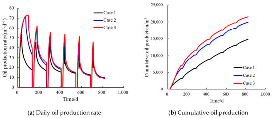
Figure 3.
Comparison of cumulative oil production for each case.
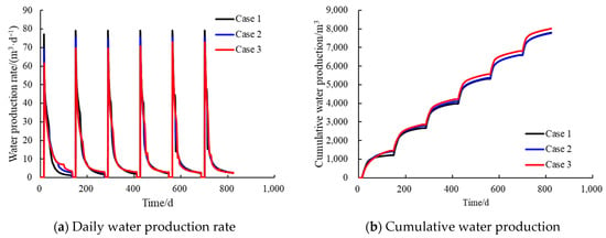
Figure 4.
Comparison of cumulative water production for each case.
In stark contrast to the significant differences in oil production, the cumulative water production of the three scenarios (Figure 4) is very similar. At the end of the simulation, the cumulative water production for each scenario was around 8000 m3, with relatively small differences. This is mainly because during the CSS process, the produced water is almost entirely condensed water from the injected steam. Since the total amount of steam injected in each cycle is the same for all scenarios, the total amount of water available for backflow is also similar.
To provide a direct insight into the production and thermal efficiency, key performance indicators are plotted in Figure 5. Figure 5a compares the dynamic water cut for the three cases. It clearly shows that Case 3 consistently maintains the lowest water cut throughout the production period, indicating the highest production efficiency. In contrast, Case 1 exhibits the highest water cut, representing the lowest efficiency. Figure 5b presents the cumulative oil-steam ratio, the standard metric for thermal efficiency in CSS. This figure confirms the superior performance of Case 3, which achieves the highest OSR in every cycle, peaking at over 5.0 in the first cycle and finishing with a final cumulative OSR of approximately 2.7. This high efficiency is attributed to the large contact area of the radial wells effectively utilizing the reservoir’s high elastic energy, as discussed previously.
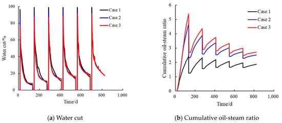
Figure 5.
Comparison of water cut and cumulative oil-steam ratio for each case.
Taken together, the analyses of Figure 5a,b confirm that the dual-layer radial well strategy (Case 3) is superior in both production efficiency and thermal efficiency.
3.2.2. Analysis of Physical Field Evolution
To gain a deeper mechanistic understanding of the fundamental reasons for the differences in production dynamics among the different well type scenarios, a detailed analysis of the evolution of key reservoir physical fields (pressure, temperature, oil saturation) during the simulation process was conducted. Figure 6, Figure 7 and Figure 8 show the distribution of these physical fields for the horizontal well (Case 1), single-layer radial well (Case 2), and dual-layer radial well (Case 3) at four key time points: after steam injection and at the end of production in the first and sixth cycles. To more clearly observe the distribution of physical fields within the reservoir, the single horizontal well and single-layer radial well scenarios are sectioned through the middle of the reservoir, while the dual-layer radial well is sectioned at the level of the lower branch layer near the reservoir bottom.
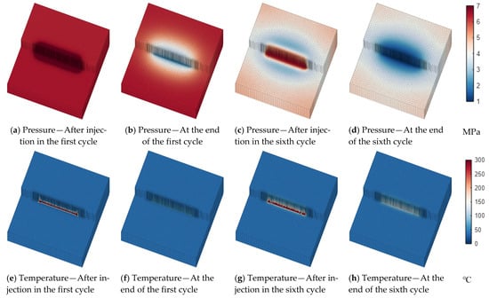

Figure 6.
Distribution of physical fields at different cycles for horizontal well development.

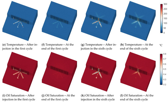
Figure 7.
Distribution of physical fields at different cycles for single-layer radial well development.
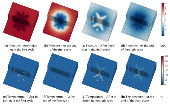

Figure 8.
Distribution of physical fields at different cycles for dual-layer radial well development.
The evolution of the pressure field directly reflects the energy changes in the reservoir. In all scenarios, each cycle exhibits a periodic pattern of increased pressure in the near-wellbore region during steam injection and decreased pressure during production. As the CSS cycles progress, the average pressure of the entire reservoir shows a significant decline. Comparing the pressure distribution at the end of the first cycle with that at the end of the sixth cycle, the latter has a wider low-pressure area and lower pressure values. This indicates that as fluids are continuously produced, the reservoir energy is steadily depleted, but there are significant differences in the rate of pressure decline among the scenarios. At the end of the sixth cycle, the low-pressure zone in the horizontal well scenario (Figure 6d) is mainly confined to the vicinity of the wellbore, whereas the low-pressure zones in the single-layer (Figure 7d) and dual-layer radial well scenarios (Figure 8d) are significantly larger, with a more pronounced pressure drop. This suggests that the radial well scenarios can more efficiently drain and produce fluids from a larger reservoir area, leading to a faster depletion of reservoir energy, a phenomenon that is consistent with their higher oil production results.
There are also significant differences in the temperature and oil saturation fields among the three scenarios. For the horizontal well scenario (Figure 6), its heating and oil displacement range is limited on the planar level. Heat (Figure 6e,g) and the mobilized oil (Figure 6i,k) are consistently confined to a narrow, elongated area around the wellbore. In contrast, for the single-layer radial well scenario (Figure 7), the multiple radial branches allow steam to radiate outwards in all directions, greatly increasing the sweep area and uniformity on the planar level. From the temperature field (Figure 7e,g), it can be seen that a star-shaped heating zone is formed from the very first cycle, which is far superior to the linear heating pattern of the horizontal well. Correspondingly, the decrease in oil saturation (Figure 7i,k) also shows a star-shaped distribution consistent with the heated zone, indicating that oil is effectively mobilized over a broader planar area. The dual-layer radial well scenario achieves maximum reservoir contact and sweep by deploying radial well networks at two levels. This is not merely an expansion on a single plane but the construction of a three-dimensional heating method. It is this more significant reservoir contact and sweep capability that enables it to heat and produce crude oil most efficiently, ultimately manifesting as the fastest pressure decline and the highest cumulative oil productions.
In summary, the evolution of the physical fields clearly demonstrates the production enhancement mechanism of radial wells, particularly dual-layer radial wells: through their unique wellbore structure, they achieve a broader and more uniform steam sweep on the planar level, thereby effectively heating and mobilizing a larger volume of the reservoir, which ultimately leads to a substantial improvement in production performance.
4. Discussion
The primary objective of this study was to establish and validate a robust numerical method for simulating complex radial well geometries, which was achieved. However, this study focused on the methodology rather than a comprehensive parametric investigation. We identify the following limitations and directions for future work:
- 1.
- The current work includes only a preliminary sensitivity analysis on the wellbore geometry (Cases 1–3). The impacts of key operational parameters and geological uncertainties were not investigated.
- 2.
- The validated model developed in this study provides a robust, high-fidelity tool. This opens avenues for important future research, such as simulating advanced hybrid processes (e.g., steam-solvent), generating reliable data for training AI-based surrogate models, and performing detailed economic and environmental impact analyses based on the accurate physical predictions [22,34].
- 3.
- This study focused on the thermo-hydraulic mechanism rather than economic feasibility. The 44.8% production gain shown for Case 3 is specific to our model parameters and must be weighed against the significantly higher drilling costs and operational risks of multi-layer radial drilling. A comprehensive techno-economic analysis, which would also include a detailed study of the technology’s performance under various steam override scenarios, is required before any field-scale deployment.
5. Conclusions
- (1)
- Based on unstructured grid technology, a numerical simulation method capable of accurately simulating the thermal recovery process of heavy oil with complex well types has been successfully established and validated in this study. This method uses PEBI unstructured grids to finely represent the geometry of radial well branches at any azimuth and level, effectively overcoming the limitations of traditional structured grids that are prevalent in many commercial simulators. Validation through comparison with the commercial software CMG demonstrates that the model’s calculation results are accurate and reliable, providing a powerful tool for in-depth research of radial well CSS technology.
- (2)
- The comparison of production dynamics for different well type scenarios shows that radial wells can significantly enhance the development effect of CSS. Compared with a conventional horizontal well, the final cumulative oil production of single-layer and dual-layer radial wells increased by 34.2% and 44.8%, respectively. Among the studied scenarios, the dual-layer radial well exhibited the highest peak production in each cycle and the highest final cumulative production, making it the optimal well type choice under the specific conditions and parameters investigated in this study.
- (3)
- The analysis of physical field evolution reveals the production enhancement mechanism of radial wells. Their core advantage lies in the wellbore structure, which greatly optimizes the efficiency of heat sweep in the plane. Compared to the linear, confined heating pattern along the wellbore of a horizontal well, a radial well forms a broader and more uniform radial heating zone by injecting steam through multi-directional branches. This allows for the mobilization of a larger reservoir volume, achieving more efficient energy utilization and crude oil recovery.
Supplementary Materials
The following supporting information can be downloaded at: https://www.mdpi.com/article/10.3390/pr13113694/s1.
Author Contributions
Conceptualization, T.Y. and Z.Z.; Software, T.Y., Z.Z. and Y.L. (Yipu Li); Validation, Y.L. (Yongge Liu); Formal analysis, Y.L. (Yipu Li), A.L. and D.C.; Investigation, T.Y., Z.Z. and L.C.; Resources, Y.L. (Yipu Li); Data curation, Y.L. (Yongge Liu) and A.L.; Writing—original draft, T.Y. and Z.Z.; Supervision, Y.L. (Yipu Li); Project administration, Y.L. (Yongge Liu) and L.C. All authors have read and agreed to the published version of the manuscript.
Funding
This study is supported by State Key Laboratory of Deep Oil and Gas (Grant No. SKLDOG2024-ZYTS-09; SKLDOG2024-ZYRC-04), the Natural Science Foundation of Shandong Province (Grant No. ZR2025MS980), and the Taishan Scholars Program.
Data Availability Statement
The original contributions presented in this study are included in the article and Supplementary Material. Further inquiries can be directed to the corresponding authors.
Conflicts of Interest
Authors Tiantian Yu, Zhaoxiang Zhang and Liyuan Chen were employed by the Shengli Oilfield Branch. The remaining authors declare that the research was conducted in the absence of any commercial or financial relationships that could be construed as a potential conflict of interest.
References
- Wang, C.; Jin, H.; Fan, C.; Luo, K.; Guo, S. Exergy and energy analysis of coal gasification in supercritical water with external recycle system. Int. J. Chem. React. Eng. 2019, 17, 20190010. [Google Scholar] [CrossRef]
- Mokheimer, E.; Hamdy, M.; Abubakar, Z.; Shakeel, M.; Habib, M.; Mahmoud, M. A comprehensive review of thermal enhanced oil recovery: Techniques evaluation. J. Energy Resour. Technol. 2019, 141, 030801. [Google Scholar] [CrossRef]
- Zhang, J. Performance of high temperature steam injection in horizontal wells of heavy oil reservoirs. Energy 2023, 282, 128863. [Google Scholar] [CrossRef]
- Suranto, A.; Permadi, A.; Bae, W. Smart completion design in cyclic steam stimulation process: An alternative for accelerating heavy oil recovery. Int. J. Oil Gas Coal Technol. 2016, 11, 127–140. [Google Scholar] [CrossRef]
- Elkamel, L.; Sedaee, B. Influences of reservoir rock and fluid properties on cyclic steam stimulation efficiency in naturally fractured reservoirs. Int. J. Oil Gas Coal Technol. 2021, 28, 354–373. [Google Scholar] [CrossRef]
- Guo, K.; Li, H.; Yu, Z. In-situ heavy and extra-heavy oil recovery: A review. Fuel 2016, 185, 886–902. [Google Scholar] [CrossRef]
- Li, Y.; Wang, Z.; Hu, Z.; Xu, B.; Li, Y.; Pu, W.; Zhao, J. A review of in situ upgrading technology for heavy crude oil. Petroleum 2021, 7, 117–122. [Google Scholar] [CrossRef]
- Shah, A.; Fishwick, R.; Wood, J.; Leeke, G.; Rigby, S.; Greaves, M. A review of novel techniques for heavy oil and bitumen extraction and upgrading. Energy Environ. Sci. 2010, 3, 700–714. [Google Scholar] [CrossRef]
- Sun, F.; Yao, Y.; Li, X.; Yu, P.; Ding, G.; Zou, M. The flow and heat transfer characteristics of superheated steam in offshore wells and analysis of superheated steam performance. Comput. Chem. Eng. 2017, 100, 80–93. [Google Scholar] [CrossRef]
- Fan, J.; Li, X.; Qin, T. Feasibility study on steam and gas push with dual horizontal wells in a moderate-depth heavy oil reservoir. J. Eng. Sci. Technol. Rev. 2015, 9, 151–158. [Google Scholar] [CrossRef]
- Hou, J.; Zhou, K.; Zhao, H.; Kang, X.; Wang, S.; Zhang, X. Hybrid optimization technique for cyclic steam stimulation by horizontal wells in heavy oil reservoir. Comput. Chem. Eng. 2016, 84, 363–370. [Google Scholar] [CrossRef]
- Wang, B.; Huang, S.; Zhao, F.; Su, Z.; Fan, X.; Yang, M. Investigating the heated zone evolution and production performance of cyclic steam stimulation with horizontal well in thick-layer heavy oil reservoirs. Geoenergy Sci. Eng. 2024, 241, 213108. [Google Scholar] [CrossRef]
- Closman, P. Steam Zone Growth During Multiple-Layer Stream Injection. SPE J. 1967, 7, 1–10. [Google Scholar] [CrossRef]
- Satman, A. An analytical study of transient flow in stratified systems with fluid banks. In Proceedings of the SPE Annual Technical Conference and Exhibition, San Antonio, TX, USA, 4–7 October 1981. SPE-10264-MS. [Google Scholar] [CrossRef]
- Stanislav, F.; Easwaran, C.; Kokal, S. Interpretation of thermal well Falloff testing. SPE J. 1989, 4, 181–186. [Google Scholar] [CrossRef]
- Li, X.; Xiao, W.; Qu, Z.; Guo, T.; Li, J.; Zhang, W.; Tian, Y. Rules of fracture propagation of hydraulicfracturing in radial well based on XFEM. J. Pet. Explor. Prod. Technol. 2018, 8, 1547–1557. [Google Scholar] [CrossRef]
- Huang, Z.; Huang, Z.; Su, Y.; Bi, G.; Liu, X.; Jiang, T. A feasible method for the trajectory measurement of radial jet drilling laterals. SPE Drill. Complet. 2020, 35, 125–135. [Google Scholar] [CrossRef]
- Bruni, M.; Biasotti, H.; Salomone, G. Radial Drilling in Argentina. In Proceedings of the Latin American & Caribbean Petroleum Engineering Conference, Buenos Aires, Argentina, 15–18 April 2007. SPE-107382-MS. [Google Scholar] [CrossRef]
- East, L.E., Jr.; Grieser, W.; McDaniel, B.; Johnson, B.; Jackson, R.; Fisher, K. Successful Application of Hydrajet Fracturing on Horizontal Wells Completed in a Thick Shale Reservoir. In Proceedings of the SPE Eastern Regional Meeting, Charleston, WV, USA, 15–17 September 2004. SPE-91435-MS. [Google Scholar] [CrossRef]
- Gu, M.; Sheng, M.; Zhang, B.; Tian, S.; Li, G. Local Stress Reconstruction of Multi Radial Wells for Enhancing Stimulated Height of Shale Oil Reservoir. Rock Mech. Rock Eng. 2024, 57, 10673–10693. [Google Scholar] [CrossRef]
- Liu, X.; Han, Z.; Yu, L.; Wei, W.; Lu, H.; Sun, Y. Hydrate Reservoir Stimulation and Sand Control by Liquid-Solid Phase Change Proppant Filled in Radial Well. SPE J. 2023, 28, 2003–2020. [Google Scholar] [CrossRef]
- Sun, H.; Wang, H.; Cao, X.; Shu, Q.; Fan, Z.; Wu, G.; Yang, Y.; Wu, Y. Innovations and applications of the thermal recovery techniques for heavy oil. Energy Geosci. 2024, 5, 100332. [Google Scholar] [CrossRef]
- Li, P.; Wang, X.; Zhang, Y. Thermal recovery of heavy oil reservoirs: Modeling of flow and heat transfer characteristics of superheated steam in full-length concentric dual-tubing wells. Geoenergy Sci. Eng. 2025, 244, 213432. [Google Scholar] [CrossRef]
- Wang, F.; Kobina, F. The Influence of Geological Factors and Transmission Fluids on the Exploitation of Reservoir Geothermal Resources: Factor Discussion and Mechanism Analysis. Reserv. Sci. 2025, 1, 3–18. [Google Scholar] [CrossRef]
- Li, Q. Reservoir Science: A Multi-Coupling Communication Platform to Promote Energy Transformation, Climate Change and Environmental Protection. Reserv. Sci. 2025, 1, 1–2. [Google Scholar] [CrossRef]
- Liu, Y.; Hou, J.; Zhao, H.; Liu, X.; Xia, Z. A method to recover natural gas hydrates with geothermal energy conveyed by CO2. Energy 2018, 144, 265–278. [Google Scholar] [CrossRef]
- Li, Y.; Wu, N.; Gao, D.; Chen, Q.; Liu, C.; Yang, D.; Jin, Y.; Ning, F.; Tan, M.; Hu, G. Optimization and analysis of gravel packing parameters in horizontal wells for natural gas hydrate production. Energy 2021, 219, 119585. [Google Scholar] [CrossRef]
- Guo, T.; Hao, T.; Chen, M.; Zhang, Y.; Qu, Z.; Jia, X.; Zhang, W.; Yu, H. Numerical simulation on Geothermal extraction by radial well assisted hydraulic fracturing. Renew. Energy 2023, 210, 440–450. [Google Scholar] [CrossRef]
- He, J. Numerical simulation of a Class I gas hydrate reservoir depressurized by a fishbone well. Processes 2023, 11, 771. [Google Scholar] [CrossRef]
- Wang, R.; Lei, Z.; Han, J.; Yang, Y.; Yan, Y. Complex fracture description and quasi-elastic energy development mathematical model for shale oil reservoirs. Front. Energy Res. 2024, 12, 1407183. [Google Scholar] [CrossRef]
- IAPWS-IF97; Industrial Formulation 1997 for the Thermodynamic Properties of Water and Steam. International Association for the Properties of Water and Steam (IAPWS): Erlangen, Germany, 1997.
- Peaceman, D. Interpretation of well-block pressures in numerical reservoir simulation with nonsquare grid blocks and anisotropic permeability. SPE J. 1983, 23, 531–543. [Google Scholar] [CrossRef]
- Liu, H.; Chen, Z. A scalable thermal reservoir simulator for Giant models on parallel computers. arXiv 2018, arXiv:1812.03952. [Google Scholar] [CrossRef]
- Jin, B.; Xu, X. Price forecasting through neural networks for crude oil, heating oil, and natural gas. Meas. Energy 2024, 1, 100001. [Google Scholar] [CrossRef]
Disclaimer/Publisher’s Note: The statements, opinions and data contained in all publications are solely those of the individual author(s) and contributor(s) and not of MDPI and/or the editor(s). MDPI and/or the editor(s) disclaim responsibility for any injury to people or property resulting from any ideas, methods, instructions or products referred to in the content. |
© 2025 by the authors. Licensee MDPI, Basel, Switzerland. This article is an open access article distributed under the terms and conditions of the Creative Commons Attribution (CC BY) license (https://creativecommons.org/licenses/by/4.0/).