Article

Load Frequency Control of Power Systems Based on Deep Reinforcement Learning with Leader–Follower Consensus Control for State of Charge

1
State Grid Shandong Electric Power Research Institute, Ji’nan 250003, China
2
School of Automation Science and Engineering, Xi’an Jiaotong University, Xi’an 710049, China
3
School of Cyber Science and Engineering, Xi’an Jiaotong University, Xi’an 710049, China
*
Author to whom correspondence should be addressed.
Processes 2025, 13(11), 3669; https://doi.org/10.3390/pr13113669
Submission received: 3 October 2025 / Revised: 31 October 2025 / Accepted: 10 November 2025 / Published: 13 November 2025

Abstract

With the extensive integration of renewable energy sources (RESs), power systems face challenges in load frequency control (LFC) due to RES intermittency. While energy storage systems (ESSs) aid frequency regulation, existing strategies are limited—single-type ESSs fail in multi-ESS scenarios, and hybrid ESSs lack state-of-charge (SoC) consistency control. This paper proposes an LFC framework combining energy storage aggregators (ESAs), leader–follower finite-time consensus control, and DDPG-RNN (Deep Deterministic Policy Gradient with Recurrent Neural Networks). ESAs aggregate small distributed ESSs for scalable regulation; consensus control ensures finite-time ESS power tracking and SoC balancing; and DDPG-RNN adaptively tunes control gains to handle RES fluctuations and load changes. Simulations on a high-RES power system with hybrid ESSs (SCES, LABES, VRFBES, LIPBES) show that the framework outperforms traditional proportional–integral–derivative (PID) control and basic leader–follower control: it reduces frequency deviation peaks, shortens recovery time, achieves SoC synchronization, and alleviates conventional generator power fluctuations.

1. Introduction

Global energy shortages, ecological pollution, and climate deterioration constrain global development. This has driven global consensus on accelerating low-carbon energy transitions and boosting renewable energy share, spurring sustained growth in renewable energy demand [1,2,3]. Renewable energy’s rapid development fuels the energy transition. However, it poses critical challenges to power grids. Converter-connected units lack the rotational inertia of synchronous generators [4], leading to low-inertia and weak-damping grids. Extreme weather triggers sharp fluctuations in renewable energy output [5], worsening grid stability risks. Rising renewable penetration also reduces system inertia and frequency regulation reserves [6,7], increasing vulnerability to frequency deviations. Traditional frequency regulation schemes fall short. Synchronous generators in large plants were once the primary solution. But thermal units suffer from slow response, limited ramping, and poor tracking accuracy [8], causing regulatory inefficiencies. Hydropower units, though faster in response, are constrained by geographical and seasonal factors [9]. These limitations highlight the urgent demand for fast, high-performance frequency regulation resources in high-renewable-energy grids.
Energy storage systems (ESSs) offer a techno-economically viable solution. They feature fast response (suppressing load fluctuations in seconds), bidirectional power switching, and high-precision output [10]. Outperforming traditional synchronous generators, ESSs support both primary and secondary frequency regulation [11,12]. They alleviate burdens on grids and conventional units, improve regulation efficiency, and ensure frequency stability. Experimental analyses further reveal that under identical power and capacity conditions, ESSs exhibit 25 times the regulation capability of thermal units without a dead band and 12.5 times with a dead band [13]; a 10 MW ESS can even substitute for a 36 MW thermal unit in frequency regulation, achieving 3.6 times the efficiency [14]. Economically, ESSs achieve the highest returns when deployed in frequency regulation compared to other applications, such as wind power peak shaving or ramp rate control [15]. Life-cycle economic evaluation models [16] and profit models incorporating regulation mileage compensation, AGC capacity compensation, and cost components (construction and maintenance) [17] have validated the economic feasibility of ESS-assisted frequency regulation. By integrating ESSs into frequency regulation, conventional generation units can be relieved from intensive regulation duties, reducing mechanical wear and extending operational lifetime [18].
Research on ESS integration in load frequency control (LFC) has evolved along two primary paths: single-type ESSs and hybrid ESSs. In the case of single-type ESSs, multiple control and allocation strategies have been proposed. Reference [19] introduced a rolling optimization strategy based on dynamic simulation, allocating AGC commands to thermal units and ESSs via a multi-objective grid adaptive search algorithm (on a 1 min scale) that considers both ESS state of charge (SoC) and regulation costs to optimize overall LFC performance. Reference [20] analyzed the frequency characteristics of secondary regulation under both Area Control Error (ACE) and Area Regulation Requirement (ARR) signal modes using sensitivity principles, establishing activation timing, regulation mode, and action depth for ESSs based on dynamic regulation capacity indicators to enhance grid frequency stability. Reference [21] applied ensemble empirical mode decomposition (EEMD) to decompose ACE signals and allocated AGC commands by trading off economic benefits, regulation performance of ESSs and thermal units, and operational constraints, thereby improving both frequency stability and ESS economy. Reference [22] proposed an ESS-assisted AGC strategy for thermal units, using ESSs to compensate for deviations between thermal unit output and regulation commands, thus improving generator performance. Nevertheless, these studies concentrate solely on single-type battery ESSs, rendering them inadequate for scenarios involving multiple ESS technologies cooperating in frequency regulation.
For hybrid ESSs, which combine multiple storage technologies, several studies have addressed coordination among different ESS types but still exhibit limitations. Reference [23] applied droop control to a hybrid ESS consisting of batteries and supercapacitors. It incorporated frequency and voltage compensation loops to mitigate steady-state deviations of traditional droop control. Additionally, the study considered ESS SoC to prevent overcharging or over-discharging, thereby extending the ESS service life. Reference [24] categorized the operational states of a hybrid ESS (composed of lead–acid and vanadium redox flow batteries) into five scenarios according to thermal unit status, hybrid ESS characteristics, and SoC, and designed corresponding control strategies for each. Despite these contributions, existing studies on hybrid ESSs overlook the coordinated control of multiple storage units, particularly the absence of SoC consistency control among different ESS units within the hybrid system. This gap can result in uneven SoC distribution, premature shutdown of ESSs due to SoC limits, and diminished overall regulation capability of the hybrid system.
For hybrid ESSs, which combine multiple storage technologies, several studies have addressed coordination among different ESS types but still exhibit limitations. Reference [23] applied droop control to a hybrid ESS consisting of batteries and supercapacitors. It incorporated frequency and voltage compensation loops to mitigate steady-state deviations of traditional droop control. Additionally, the study considered ESS SoC to prevent overcharging or over-discharging, thereby extending the ESS service life. Reference [24] categorized the operational states of a hybrid ESS (composed of lead-acid and vanadium redox flow batteries) into five scenarios according to thermal unit status, hybrid ESS characteristics, and SoC, and designed corresponding control strategies for each. Reference [25] proposed a hierarchical coordinated control strategy considering state of charge (SoC) consensus for large-scale battery ESSs participating in power system secondary frequency regulation, which maintains SoC within the normal operating range and achieves SoC consistency among ESS units. Reference [26] introduced a load frequency control scheme with energy storage aggregators (ESAs) and a finite-time leader–follower consensus algorithm, ensuring ESSs track frequency control signals while balancing SoC in finite time. Despite these contributions, existing studies on hybrid ESSs overlook the coordinated control of multiple storage units, particularly the absence of comprehensive SoC consistency control among different ESS units within the hybrid system. This gap can result in uneven SoC distribution, premature shutdown of ESSs due to SoC limits, and diminished overall regulation capability of the hybrid system.
To overcome these challenges—including inadequate frequency regulation capacity in high-RES penetration grids, limited applicability of single-ESS strategies, and the lack of SoC consistency control in hybrid ESSs—this paper proposes a novel load frequency control (LFC) framework based on energy storage aggregators (ESAs) with adaptive consensus control. Compared with existing renewable energy source (RES) integration techniques and frequency regulation algorithms, the unique contributions of this work are as follows:
  • While existing studies focus either on either single large-scale ESSs or simple aggregation of distributed ESSs without considering system scalability, this paper adopts the ESA concept to aggregate numerous small-scale distributed ESSs. This not only resolves the long-standing issue of individual small ESSs being unable to effectively participate in grid regulation due to limited capacity but also enables the aggregated ESA to function as a unified entity from the system operator’s perspective—significantly improving scalability and plug-and-play flexibility, which are rarely addressed in existing aggregation-based strategies.
  • Unlike conventional consensus control algorithms for ESS coordination that suffer from slow convergence and fail to simultaneously optimize power tracking and SoC balancing, a leader–follower finite-time consensus control algorithm is proposed. This algorithm guarantees finite-time convergence of both ESS power tracking accuracy and SoC balancing, addressing the dynamic regulation inefficiencies of existing methods and enhancing the transient and steady-state performance of the LFC system.
  • In contrast to fixed-gain control strategies that lack adaptability to stochastic RES output variations and sudden load changes, this paper employs a Deep Deterministic Policy Gradient (DDPG) algorithm integrated with Recurrent Neural Networks (RNNs) to adaptively adjust consensus control gains. The RNN’s ability to capture temporal dependencies and DDPG’s advantage in optimizing continuous control actions enable the framework to dynamically respond to grid uncertainties—strengthening the robustness of the ESA-LFC system and ensuring stable frequency regulation under complex dynamic operating conditions, which is a key improvement over existing adaptive control schemes that ignore temporal characteristics of grid disturbances.

2. LFC Framework with Energy Storage Aggregators

2.1. System Architecture Overview

The proposed frequency control framework comprises two interconnected components: (i) a secondary LFC mechanism that leverages ESAs to augment regulation capacity, and (ii) a finite-time consensus strategy for ESA coordination, where control parameters are dynamically optimized through a DDPG algorithm enhanced with RNNs. Section 3 elaborates on the consensus methodology, while Section 4 details the DDPG-RNN adaptive tuning mechanism.
The ESA’s frequency control signal ( P ESA * ( t ) ) originates from the Automatic Generation Control (AGC) layer, with a predetermined participation factor allocating regulation effort between conventional generators and the ESA. Within the ESA, a designated leader node transforms this signal into reference states—specifically, a normalized power reference p 0 ( t ) and an energy reference e 0 ( t ) .
Individual energy storage units within the ESA are coordinated through a directed communication topology 𝒢 ¯ (comprising one leader and multiple followers) to follow these reference states. Each ESS is characterized as a double-integrator dynamical system, representing the coupling between its state of charge (SoC, denoted e i ( t ) ) and power output ( p i ( t ) ). The DDPG-RNN framework continuously adapts consensus control gains to achieve finite-time state synchronization, thereby ensuring effective SoC management while maintaining precise tracking of AGC commands for fast frequency support.

2.2. LFC Framework

This study examines a two-area interconnected power system integrated with the ESA. The corresponding LFC structure is illustrated in Figure 1. Primary control limits frequency excursions caused by power imbalances, while secondary control restores the nominal frequency. The dynamics of each control area i ( i = 1 , 2 ) are governed by Equations (1)–(6). The frequency deviation dynamic (Area i) is
Δ f ˙ i ( t ) = D i 2 H i Δ f i ( t ) + 1 2 H i Δ P m i ( t ) Δ P L i ( t ) + Δ P ESA i ( t ) γ tie Δ f tie ( t )
where Δ f i ( t ) denotes the frequency deviation of area i; D i is the damping coefficient of area i; 2 H i represents the system inertia time constant of area i (s); Δ P m i ( t ) is the mechanical power deviation of the generator in area i; Δ P L i ( t ) indicates the load power deviation in area i; Δ P ESA i ( t ) is the output power deviation of the ESA in area i; Δ f tie ( t ) = Δ f 1 ( t ) Δ f 2 ( t ) is the inter-area frequency deviation; and γ tie is the tie-line coefficient. For Area 1, the term γ tie Δ f tie ( t ) accounts for power exchange with Area 2; for Area 2, this term becomes + γ tie Δ f tie ( t ) (consistent with directional power flow in Figure 1).
The turbine dynamic (Area i) is
Δ P ˙ m i ( t ) = 1 T t i Δ P m i ( t ) + 1 T t i Δ P g i ( t )
where T t i is the turbine time constant of area i (s); Δ P g i ( t ) denotes the governor output power deviation in area i.
The governor dynamic (Area i) is
Δ P ˙ g i ( t ) = 1 T g i Δ P g i ( t ) + 1 T g i Δ P c i ( t ) 1 R i T g i Δ f i ( t )
where T g i is the governor time constant of area i (s); R i is the droop characteristic of area i; and Δ P c i ( t ) is the secondary control command of area i.
Each area’s secondary control input responds to its ACE, defined as
A C E i ( t ) = β i Δ f i ( t ) + Δ P tie i ( t )
where A C E i ( t ) is the Area Control Error (ACE) of area i; β i = D i + 1 / R i is the frequency bias coefficient of area i; and Δ P tie i ( t ) = γ tie Δ f tie ( t ) d t is the tie-line power deviation of area i.
Conventional LFC employs proportional–integral (PI) control to eliminate steady-state errors:
Δ P c i ( t ) = K P i A C E i ( t ) K I i A C E i ( t ) d t
where K P i and K I i are the proportional and integral gains for Area i, respectively. Traditional secondary control may require up to 10 min for complete frequency recovery.
As shown in Figure 1, the ESA in Area 1 consists of multiple ESSs coordinated via a communication network. The ESA offers enhanced controllability, flexibility, and scalability, making it suitable for providing supplementary frequency support. In Area 1, Δ P c 1 ( t ) is divided into two parts through proportional allocation, which are, respectively, used for conventional generator unit regulation and ESA-aided frequency regulation to achieve multi-resource coordinated control. Specifically, Δ P ESA i ( t ) is the aggregated power output of all ESSs in Area i, and each ESS’s SoC dynamic is governed by
SoC ˙ j = K ESS j Δ P ESS j ( t )
where SoC ˙ j is the rate of change of state of charge (SoC) for the j-th ESS; Δ P ESS j ( t ) is the output power deviation of the j-th ESS; and K ESS j is the capacity coefficient of the j-th ESS, ensuring coordinated power regulation while maintaining SoC balance.

3. Leader–Follower Consensus Coordination Strategy for ESSs

3.1. Communication Network Structure

The communication infrastructure for an energy storage aggregation (ESA), consisting of multiple distributed energy storage units (ESSs), can be represented by a graph 𝒢 = ( 𝒱 , E ) . Here, 𝒱 = { v 1 , v 2 , , v N } denotes the set of nodes (each corresponding to an ESS), while E 𝒱 × 𝒱 defines the set of edges (representing communication channels between ESSs). Bidirectional communication yields an undirected graph; otherwise, the graph is directed. A directed graph contains a spanning tree if a root node exists with directed paths to all other nodes.
The connectivity pattern is captured by an adjacency matrix A = [ a i j ] R N × N , where
a i j = 1 , if   ( v i , v j ) E 0 , otherwise
The in-degree matrix Δ is a diagonal matrix defined as Δ = diag { δ 1 , δ 2 , , δ N } , where δ i = j = 1 N a i j represents the in-degree of node v i . The Laplacian matrix L of 𝒢 is given by L = Δ A , with elements
l i j = a i j , i j j N i N a i j , i = j
where N i indicates the neighbor set of v i . Notably, each row of L sums to zero.
For an ESA with a leader node v 0 , the extended topology is described by 𝒢 ¯ = ( 𝒱 ¯ , E ¯ ) , which includes the original graph 𝒢 , the leader node v 0 , and edges ( v 0 , v i ) E ¯ from the leader to followers. The leader transmits information to followers unidirectionally. A diagonal matrix G = diag { g 1 , g 2 , , g N }
g i = 1 , if   ( v 0 , v i ) E ¯ 0 , otherwise
Convergence of the leader–follower consensus algorithm requires that 𝒢 ¯ contains a spanning tree rooted at v 0 and that all eigenvalues of L + G possess positive real parts.

3.2. Consensus-Based Coordination Strategy

This section presents a leader–follower consensus approach for coordinating ESSs within an ESA to support frequency regulation while maintaining state-of-charge (SoC) balance. The modeling and control design proceed as follows.
The actual power output of the i-th ESS is expressed as
P ESS , i ( t ) = p i ( t ) · P ESS , i max
where P ESS , i max denotes the power rating (MW) of the i-th ESS, and p i ( t ) [ 1 , 1 ] represents a normalized power state (constrained by ESS power limits).
The SoC evolution of the i-th ESS follows:
SoC i ( t ) = SoC i ( 0 ) 0 t P ESS , i ( τ ) 3600 × E ESS , i d τ
where E ESS , i (MWh) indicates ESS capacity and SoC i ( 0 ) is the initial SoC. Normalizing SoC to [ 0 , 1 ] (reflecting capacity limits) yields e i ( t ) = SoC i ( t ) . Differentiating Equation (11) and incorporating Equation (10) establishes the relationship between SoC rate and power state:
e ˙ i ( t ) = P ESS , i max p i ( t ) 3600 × E ESS , i = K ESS , i p i ( t )
where K ESS , i is a unit-specific coefficient.
The ESA is thus modeled as a group of double-integrator systems (one per ESS):
e ˙ i ( t ) = K ESS p i ( t ) p ˙ i ( t ) = u i ( t ) , i = 1 , 2 , , N
where u i ( t ) is the control input for the i-th ESS.
A leader node (representing the ESA’s higher-level controller) processes the frequency control signal P ESA * ( t ) and produces reference states:
e ˙ 0 ( t ) = K ESS p 0 ( t ) p 0 ( t ) = P ESA * ( t ) P ESA max
where P ESA max = i = 1 N P ESS , i max is the aggregate ESA power rating, e 0 ( t ) is the reference SoC, and p 0 ( t ) is the reference power state.
To achieve consensus (i.e., all ESSs track e 0 ( t ) and p 0 ( t ) ), the control protocol is formulated as
u i ( t ) = k 1 j = 1 N a i j e i ( t ) e j ( t ) k 1 g i e i ( t ) e 0 ( t ) k 2 j = 1 N a i j p i ( t ) p j ( t ) k 2 g i p i ( t ) p 0 ( t )
where k 1 , k 2 > 0 are tunable control gains; a i j (from adjacency matrix A ) encodes inter-ESS communication links (Section A); and g i { 0 , 1 } indicates whether the i-th ESS receives information directly from the leader.
The control protocol (24) utilizes a proportional feedback structure to simultaneously achieve two primary objectives: the terms j = 1 N a i j e i ( t ) e j ( t ) and k 1 g i e i ( t ) e 0 ( t ) work collectively to synchronize the state of charge (SoC) among neighboring ESSs while driving each unit’s SoC toward the leader’s reference value e 0 ( t ) , whereas the components j = 1 N a i j p i ( t ) p j ( t ) and k 2 g i p i ( t ) p 0 ( t ) ensure alignment of power states across the network and enforce tracking of the leader’s power reference p 0 ( t ) , thereby maintaining internal state balance while fulfilling frequency regulation requirements.
Consider a Lyapunov function for tracking errors e i err = e i e 0 and p i err = p i p 0 :
V = 1 2 i = 1 N ( e i err ) 2 + 1 k 1 k 2 ( p i err ) 2
Computing the time derivative and substituting Equations (13) and (15) demonstrates that V ˙ 0 (becoming strictly negative definite when 𝒢 ¯ contains a spanning tree rooted at the leader). This guarantees asymptotic convergence: e i ( t ) e 0 ( t ) and p i ( t ) p 0 ( t ) for all i, ensuring the ESA coordinates ESSs to follow frequency control signals while maintaining SoC balance.
Gain selection involves trade-offs: larger k 1 , k 2 values accelerate response but may amplify sensitivity to communication delays or measurement noise.
Compared with traditional PID control, the proposed leader–follower consensus approach has two key surplus benefits for LFC: firstly, it features a distributed cooperative characteristic as it is designed based on a multi-node distributed cooperative mechanism, and through real-time information interaction between leader and follower nodes, it can realize coordinated power allocation and SoC balance regulation for multi-type ESSs, with its dynamic response and resource coordination capability being significantly superior to the single-node independent regulation mode of traditional PID control; secondly, it offers good fault tolerance by relying on the directed communication topology, as even if some follower ESS nodes fail, the remaining nodes can still maintain cooperative regulation capability through neighborhood communication, effectively avoiding the deterioration of LFC performance caused by single-point control failure, whereas traditional PID control lacks such a distributed fault-tolerant mechanism.

4. DDPG with RNN for Adaptive Tuning

To achieve adaptive optimization of the consensus control gains k 1 and k 2 under dynamic operating conditions (e.g., stochastic RES fluctuations, sudden load changes, and time-varying ESS SoC), a deep reinforcement learning framework combining DDPG with RNNs is developed. This framework enables real-time adjustment of k 1 and k 2 based on system states, thereby improving frequency regulation performance, accelerating ESS SoC balancing, and enhancing control robustness.
The selection of RNNs is motivated by the inherent temporal characteristics of power system frequency regulation. Unlike conventional deep reinforcement learning approaches that process static state inputs, the proposed framework requires the ability to capture temporal dependencies in system dynamics for several key reasons: Firstly, key state variables such as frequency deviation and SoC are inherently time-series data, where the current system state is highly dependent on its historical trajectory. The rate of change of frequency, oscillation patterns, and SoC convergence trends is critical for predicting system behavior and making optimal control decisions. Secondly, the load disturbances and renewable energy fluctuations that the LFC system must counteract exhibit dynamic patterns over time. An RNN’s internal memory mechanism allows it to effectively model these temporal correlations, enabling the agent to not only react to the current instantaneous state but also to anticipate near-future trends. This capability to process sequential state information allows the DDPG-RNN agent to dynamically adjust the consensus control gains k 1 and k 2 in a more foresighted and context-aware manner, leading to smoother control actions and enhanced stability compared to methods that only consider instantaneous states.
DDPG, as a model-free and off-policy reinforcement learning algorithm specifically designed for continuous action spaces, provides an ideal foundation for optimizing the continuous control gains k 1 and k 2 . While conventional DDPG processes static state inputs, the proposed framework incorporates RNNs to capture essential temporal dependencies in system dynamics—a crucial capability for frequency control applications where current states such as frequency deviation and SoC inherently depend on historical trajectories.
The environment in this model-free RL framework encapsulates the key dynamics of the power system and the energy storage aggregation. It primarily includes the following: (1) the electromechanical dynamics of the power system as described by Equations (1)–(6), which govern frequency deviations; (2) the consensus-based coordination dynamics of the ESA governed by Equations (13)–(15); and (3) the stochastic disturbances from load variations and renewable energy fluctuations. The adoption of model-free RL, specifically DDPG, is justified by the complexity of accurately modeling the transition probability distribution in the integrated power-system–ESA environment. The high-dimensional state space, nonlinear dynamics, and stochastic disturbances from renewables make it impractical to derive precise transition models. Instead, the model-free approach allows the agent to learn optimal policies directly through interaction with the environment, without requiring explicit knowledge of the system dynamics.
The architecture comprises five fundamental components: a Main Actor Network, implemented as an RNN-based network that maps time-series system states to continuous actions ( k 1 , k 2 ); a Main Critic Network, also RNN-based, which evaluates action quality through Q-value estimation Q ( s , a ) ; a Target Actor Network serving as a stable replica of the main actor for generating target actions during training; a Target Critic Network functioning as a stable copy of the main critic for computing target Q-values; and an Experience Replay Buffer that stores historical transitions ( s t , a t , r t , s t + 1 ) to break temporal correlations and enhance training stability.
The state space s t R 6 is designed to encapsulate key system dynamics and ESA operating conditions:
s t = Δ f ( t ) , Δ f s ( t ) , e 0 ( t ) , e i ( t ) , p 0 ( t ) , p i ( t )
where Δ f ( t ) represents the instantaneous frequency deviation of the power system in Hz, Δ f s ( t ) = 0 t Δ f ( τ ) d τ denotes the cumulative frequency error integral that reflects long-term frequency regulation performance, e 0 ( t ) is the reference state of charge of the leader node in the ESA, e i ( t ) indicates the SoC of the i-th ESS within the aggregation, p 0 ( t ) corresponds to the reference power state of the leader node normalized to [ 1 ,   1 ] , and p i ( t ) represents the power state of the i-th ESS similarly normalized to [ 1 ,   1 ] .
The state is fed to the RNN as a time sequence s t , s t 1 , , s t L (where L is the sequence length), enabling the network to capture temporal patterns (e.g., frequency oscillation trends, SoC convergence rates).
The action space a t R 2 directly corresponds to the consensus control gains to be tuned:
a t = k 1 ( t ) , k 2 ( t )
where k 1 ( t ) > 0 and k 2 ( t ) > 0 are constrained within practical ranges ( k min , k max ) to ensure stability of the consensus protocol.
The reward function is designed to balance three objectives: minimizing frequency deviation, synchronizing ESS states with leader references, and avoiding excessive control effort. It is defined as
r t = ω 1 | Δ f ( t ) | ω 2 i = 1 N | e i ( t ) e 0 ( t ) | ω 3 i = 1 N | p i ( t ) p 0 ( t ) | ω 4 ( k 1 2 ( t ) + k 2 2 ( t ) )
where ω 1 , ω 2 , ω 3 , ω 4 > 0 are weighting factors. The term ω 1 | Δ f ( t ) | prioritizes rapid frequency recovery. The terms ω 2 | e i e 0 | and ω 3 | p i p 0 | enforce SoC and power state synchronization among ESSs. The term ω 4 ( k 1 2 + k 2 2 ) regularizes control gains to prevent aggressive tuning. The weighting coefficients ω 1 to ω 4 in the reward function (Equation (19)) are carefully calibrated to reflect the hierarchical priorities of the control objectives. The prioritization ω 1 > ω 2 > ω 3 ω 4 is established for the following reasons: ω 1 is assigned the highest priority to enforce the primary objective of rapid frequency recovery. ω 2 is given a high weight to emphasize SOC synchronization, which is central to the long-term viability of the hybrid ESA. ω 3 is set to a medium value to ensure accurate power reference tracking, a prerequisite for effective frequency regulation and SOC balance. Finally, ω 4 acts as a regularizer with a small weight to prevent control gains from becoming excessively large without compromising the primary control goals, thereby ensuring smooth and stable controller performance.
The actor network processes sequential state information to generate optimal control gains k 1 and k 2 , employing an architecture that begins with an input layer accepting a sequence of L historical states ( s t , s t 1 , , s t L ) of dimension 6 × L , followed by two LSTM layers—the first containing 64 units with tanh activation to capture temporal dependencies, and the second comprising 32 units with tanh activation for refining temporal features—then a dense layer with 16 ReLU-activated units, and finally an output layer with 2 sigmoid-activated units whose outputs are scaled to the practical range ( k min , k max ) via Equation (27), with the entire network parameterized by θ μ and its output expressed as μ ( s t | θ μ ) = [ k 1 ( t ) , k 2 ( t ) ] . Simultaneously, the critic network estimates the Q-value Q ( s t , a t | θ Q ) to evaluate the long-term reward of executing action a t in state s t , using an architecture that takes concatenated time-series states ( 6 × L ) and actions (dimension 2) as input totaling 6 L + 2 dimensions, processes them through two LSTM layers (64 and 32 units, both with tanh activation), then a dense layer with 32 ReLU-activated units, and ultimately produces a single linear output through 1 unit, with the complete network parameterized by θ Q .
DDPG training involves iteratively updating the Main Actor/Critic Networks using experiences sampled from the replay buffer, with target networks ensuring stability [27]. Experiences ( s t , a t , r t , s t + 1 ) are stored in a buffer D of size M. During training, mini-batches of size B are sampled uniformly from D to decorrelate data and reduce training variance.
The critic is updated by minimizing the mean squared error between predicted Q-values and target Q-values. For a sampled experience ( s t , a t , r t , s t + 1 ) , the target Q-value is
y t = r t + γ Q ( s t + 1 , μ ( s t + 1 | θ μ ) | θ Q )
where γ ( 0 , 1 ) is the discount factor (prioritizing immediate vs. future rewards). Q ( · | θ Q ) and μ ( · | θ μ ) are the target critic and actor networks, respectively.
The critic loss function is
L ( θ Q ) = 1 B t = 1 B Q ( s t , a t | θ Q ) y t 2
The critic parameters θ Q are updated via gradient descent:
θ Q θ Q α Q θ Q L ( θ Q )
where α Q is the critic learning rate.
The actor is updated using the policy gradient, maximizing the expected Q-value. The actor loss function (to be minimized) is
J ( θ μ ) = 1 B t = 1 B Q ( s t , μ ( s t | θ μ ) | θ Q )
The actor parameters θ μ are updated via gradient ascent:
θ μ θ μ + α μ θ μ J ( θ μ )
where α μ is the actor learning rate. Using the chain rule, the gradient θ μ J ( θ μ ) can be expanded as
θ μ J ( θ μ ) 1 B t = 1 B a Q ( s t , a | θ Q ) | a = μ ( s t ) θ μ μ ( s t | θ μ )
To avoid instability from frequent target network updates, target networks are updated softly using a small parameter τ 1 :
θ μ τ θ μ + ( 1 τ ) θ μ
θ Q τ θ Q + ( 1 τ ) θ Q
This ensures smooth transitions in target values during training.

5. Case Study

5.1. Validation on Single-Area Power System

To verify the effectiveness and superiority of the proposed LFC framework—integrating energy storage aggregators, leader–follower finite-time consensus control, and DDPG-RNN for adaptive gain tuning—a series of simulations was conducted, with results and analyses detailed as follows. The environment changes dynamically due to several factors: First, the load disturbances and renewable energy outputs introduce stochastic and time-varying perturbations to the system. Second, the SoC of each ESS evolves continuously according to its power output, changing the operational state of the ESA. Third, the communication-based interactions among ESSs in the consensus protocol create complex, coupled dynamics that vary over time. These combined factors ensure that the environment presents non-stationary conditions, requiring adaptive control strategies.
The simulation parameters in Table 1 and Table 2 are derived from [28,29]. The load disturbance profile (Figure 2) is designed based on typical grid operation scenarios, with step changes of ± 0.01 p.u. and ± 0.02 p.u. representing common disturbance magnitudes in practical systems. The communication topology assumes ideal conditions without delays, which represents a limitation in real-world applications.
The simulation was based on a single control area power system with high RES penetration, where key parameters of the power system are listed in Table 1, forming the basis for modeling system dynamics (consistent with the LFC framework in Section 2). For the ESA, four types of ESSs with distinct technical characteristics were selected to simulate a hybrid ESS scenario: supercapacitor energy storage (SCES, specialized for ultra-fast transient response), lead–acid battery energy storage (LABES, suited for medium-duration regulation), vanadium redox flow battery energy storage (VRFBES, designed for long-duration energy shifting), and lithium iron phosphate battery energy storage (LIPBES, optimized for high-energy density and balanced performance). Their parameters (e.g., time constants, rated capacity, power limits, and SoC range) are provided in Table 2, leveraging ESSs with complementary response speeds and energy capacities to ensure adaptability to both transient and steady-state frequency regulation demands.
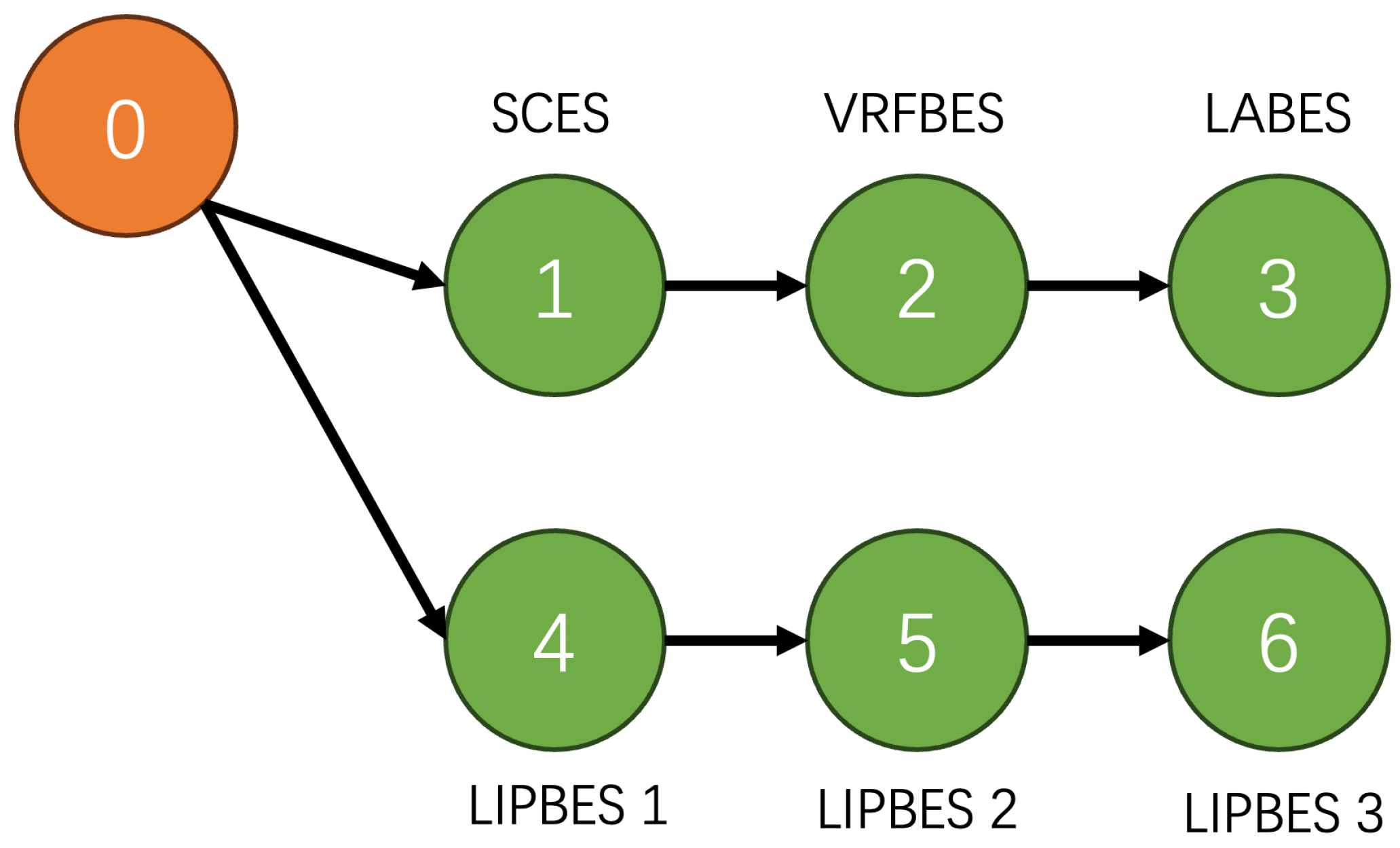
The ESA’s communication network follows the directed leader–follower structure described in Figure 3, consisting of one leader node (responsible for receiving AGC signals and generating reference states e 0 ( t ) and p 0 ( t ) ) and seven follower nodes (one SCES, one LABES, one VRFBES, and three LIPBES). The directed graph contains a spanning tree rooted at the leader node, satisfying the consensus algorithm’s convergence condition (i.e., all eigenvalues of L + G have positive real parts). To optimize the consensus control gains k 1 (for SoC synchronization) and k 2 (for power tracking), the DDPG-RNN framework was configured with key parameters selected via empirical tuning and stability analysis: an Experience Replay Buffer size M = 10 5 (to store historical state-action–reward transitions and decorrelate training data), a mini-batch size B = 64 (for stochastic gradient descent), critic/actor learning rates α Q = 10 3 / α μ = 10 3 (to balance training stability and convergence speed), a discount factor γ = 0.95 (prioritizing short-term frequency recovery while accounting for long-term SoC balance), and a soft update parameter τ = 10 3 (for smooth updates of Target Actor/Critic Networks).
To simulate real-world grid conditions, a time-varying load disturbance profile was designed (see Figure 2), including multiple step changes: ± 0.01 p.u. load fluctuations at 100 s and 300 s, and ± 0.02 p.u. load fluctuations at 500 s and 700 s, which test the system’s ability to adapt to both small-scale random variations and large-scale sudden shocks.
Figure 4 shows the DDPG-RNN agent’s reward value over training episodes: in the initial 20 episodes, rewards fluctuate significantly (ranging from 12 to 5 ) as the agent explores control gain combinations, while after 50 episodes, rewards gradually converge to a stable range ( 3 to 2 ), indicating the agent has learned to dynamically adjust k 1 and k 2 to balance frequency regulation, SoC synchronization, and control effort—confirming the RNN’s effectiveness in capturing temporal dependencies (e.g., historical frequency deviations and SoC trends) and DDPG’s ability to optimize continuous control gains.
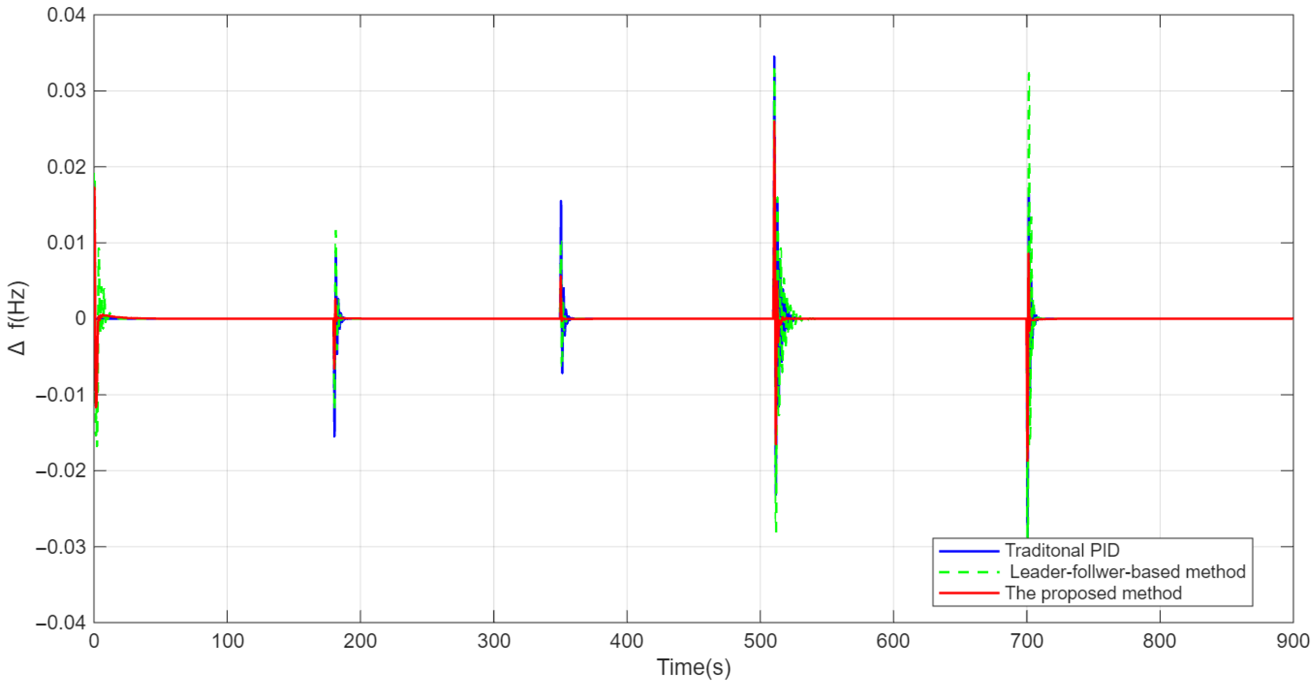
For frequency deviation performance (Figure 5), the proposed method is compared with traditional proportional–integral (PID) control and leader-based control (without DDPG-RNN adaptive tuning). Traditional PID control leads to frequency deviation peaks and a steady-state recovery time due to fixed PID gains’ inability to adapt to dynamic disturbances. Leader-based control reduces peaks but still results in slow recovery as fixed consensus gains ( k 1 , k 2 ) cannot respond to transient changes. In contrast, the proposed method limits frequency deviation and shortens steady-state recovery, as the DDPG-RNN adaptively adjusts k 1 / k 2 during disturbances (increasing k 2 for transient power tracking and k 1 for steady-state SoC balance), thus demonstrating superior frequency regulation precision and responsiveness.
Robustness under variable load disturbances (Figure 6) was tested via four extreme load steps ( 0.01 p.u., 0.01 p.u., 0.02 p.u., 0.02 p.u.). Regardless of disturbance direction or magnitude, the proposed method’s frequency deviation peaks are lower than traditional PID and lower than leader-based control, with recovery time shortened compared to benchmarks—even under the largest ( 0.02 p.u.) disturbance. This robustness stems from DDPG-RNN’s ability to learn disturbance patterns and adjust gains in real time, addressing Section 1’s highlighted challenges of stochastic RES fluctuations and sudden loads.
Mechanical power deviation of conventional generators (Figure 7) further illustrates the proposed method’s advantages: in traditional PID control, generators act as primary regulators, causing large power fluctuations from frequent adjustments; leader-based control reduces fluctuations slightly but limits the ESA’s contribution via fixed gains. The proposed method, however, leverages the ESA to absorb most load disturbances, reducing generator deviation—aligning with Section 1’s objective to relieve conventional units, reduce mechanical wear, and extend operational lifetime.
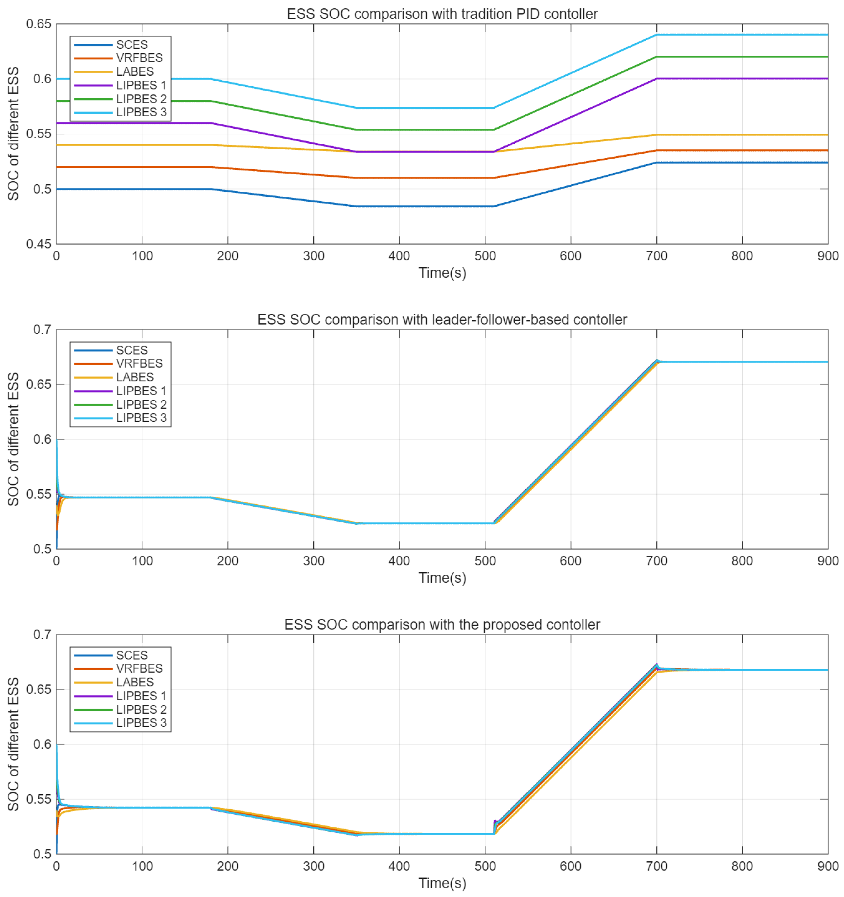
The experimental results presented in Table 3 demonstrate the superior performance of the proposed method across multiple key performance indicators. In terms of frequency regulation, the proposed method achieves the smallest maximum frequency deviation (0.0260 Hz), representing improvements of 25.3% and 30.7% compared to the traditional PID and leader–follower-based methods, respectively. Furthermore, it exhibits the fastest settling time (0.7320 s), indicating more rapid system stabilization after disturbances. Notably, the proposed method successfully achieves SOC synchronization within 5.1640 s, while the traditional PID method fails to converge, highlighting its enhanced capability in managing energy storage systems coordination. The frequency regulation stability index, which quantifies the overall frequency deviation over time, shows that the proposed method achieves the lowest value (0.0960), significantly outperforming both benchmark methods by approximately 41–61%. This substantial improvement underscores the method’s effectiveness in maintaining system frequency stability. Although the average control effort of the proposed method is comparable to the leader–follower-based approach, it achieves these results while providing superior frequency regulation and SOC synchronization performance. The maximum generator power deviation is also minimized (0.0182 p.u.), further confirming the proposed method’s ability to reduce mechanical stress on generation units while maintaining excellent frequency control performance.
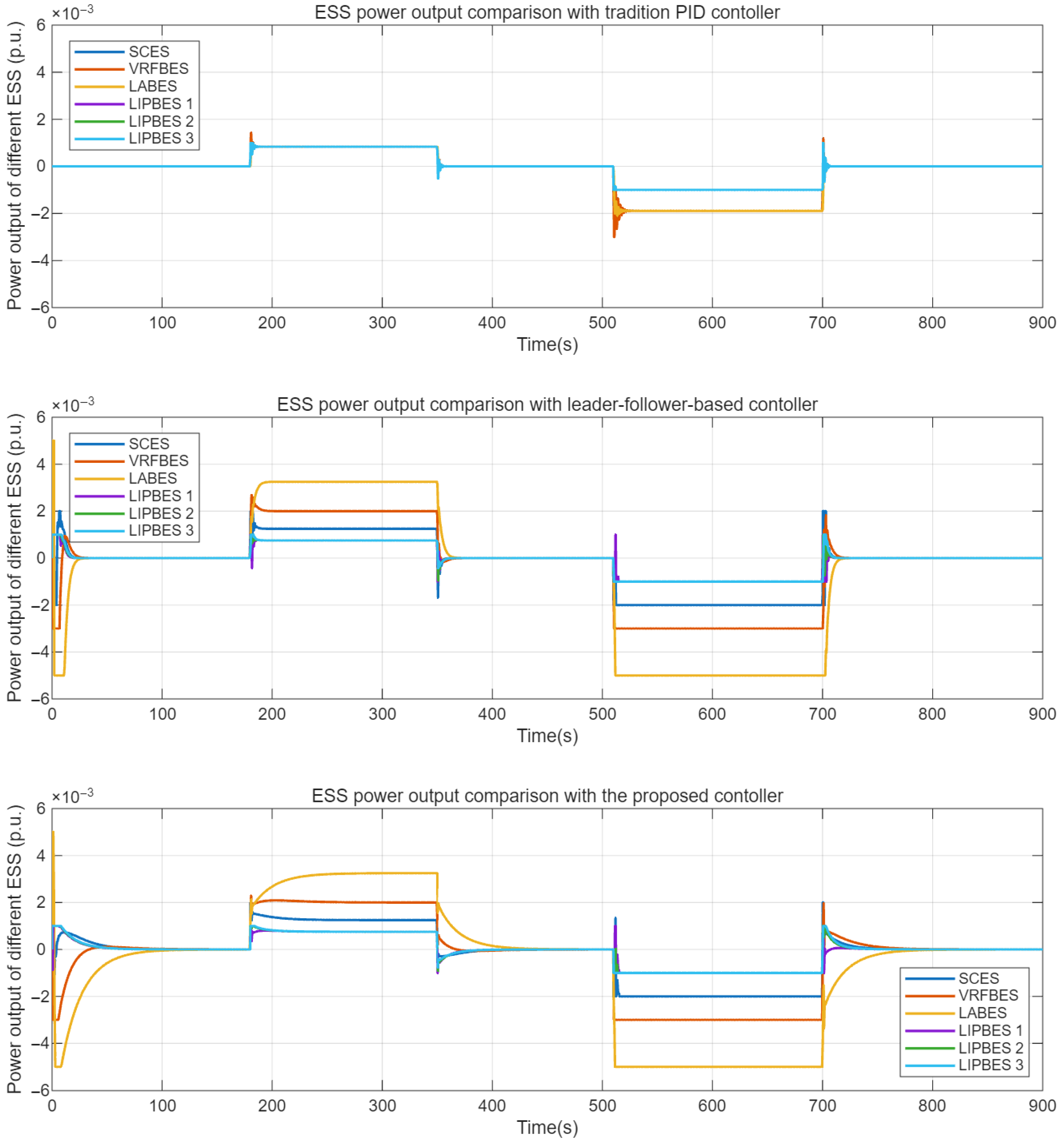
ESS power output allocation (Figure 8) highlights how the proposed method leverages hybrid ESS characteristics: SCES (ultra-fast response, low energy density) tracks high-frequency load fluctuations (−0.002 p.u. output during 510 s shocks) to maximize its rapid bidirectional power strengths while adhering to its 0.003 p.u. power limit; VRFBES and LABES (moderate speed, medium capacity) handle medium-frequency deviations (e.g., ± 0.005 p.u. output) to avoid frequent small adjustments and extend cycle life; and the three LIPBES units (high energy density, balanced response) provide base-load regulation (e.g., ± 0.001 p.u. output) with power sharing balanced by the consensus algorithm. In contrast, traditional PID and leader-based control show uncoordinated allocation (SCES is overutilized due to its fast response characteristic while LIPBES is underutilized), whereas the proposed method maximizes the hybrid ESS’s regulation potential by matching each ESS’s technical strengths to disturbance characteristics.
The superior performance of the proposed method is underpinned by the DDPG-RNN agent’s ability to dynamically adjust the consensus gains k 1 and k 2 in real time. Analysis of the system’s response reveals a logical adaptation strategy: during the transient phase immediately following a disturbance, the control action prioritizes rapid frequency stabilization, which is conceptually equivalent to an increase in the power tracking gain k 2 to ensure cohesive power output from the ESA. Subsequently, during the post-disturbance recovery phase, the focus shifts to restoring the energy state across the ESS cluster, akin to emphasizing the SoC synchronization gain k 1 to drive all units toward a balanced state. This intelligent, phase-aware gain scheduling, which fixed-gain controllers cannot replicate, allows the proposed framework to optimally balance rapid frequency regulation with sustainable ESS management, directly explaining the improved dynamic performance and convergence observed in Figure 5, Figure 6, Figure 7, Figure 8 and Figure 9 and Table 3.

5.2. Validation on Two-Area Interconnected Power System

To further validate the generalizability and effectiveness of the proposed control framework, additional simulations were conducted on a two-area interconnected power system, with the system configuration illustrated in Figure 1. In this extended test case, the proposed ESA is deployed only in Area 1, while Area 2 relies solely on conventional generation units for frequency regulation. This setup aims to verify the controller’s capability in managing both local frequency deviations and inter-area power exchanges.
Figure 10 presents the ACE comparison for both areas under three control strategies: traditional PID, leader–follower-based method, and the proposed DDPG-RNN enhanced method. The ACE, which encompasses both frequency deviations and tie-line power variations as defined in Equation (4), serves as a comprehensive indicator for evaluating the secondary frequency control performance in multi-area systems. The experimental results clearly demonstrate the superior convergence characteristics of the proposed method in both areas. As shown in Figure 10, the ACE curves under the proposed method exhibit significantly faster convergence to zero compared to the benchmark methods following load disturbances. This advantage is observed not only in Area 1 where the ESA is physically installed, but also notably in Area 2 where no ESA is deployed.
The accelerated ACE convergence in both areas can be attributed to the adaptive coordination capability of the proposed framework. The DDPG-RNN controller dynamically optimizes the consensus control gains to achieve more responsive power regulation from the ESA in Area 1. This enhanced regulation capability effectively propagates through the tie-line connection, providing improved frequency support to Area 2 and facilitating faster system-wide power balance restoration. The proposed method demonstrates better damping of inter-area oscillations and more efficient coordination between the two interconnected areas. These results conclusively verify that the proposed control framework maintains its performance advantages in multi-area power systems and exhibits excellent generalizability, even under asymmetric deployment of energy storage resources across different control areas.

6. Conclusions

This study addresses key challenges of LFC in power systems with high RES penetration. These challenges include insufficient regulation capacity, limited applicability of single-type ESSs, and lack of SoC consistency in hybrid ESSs. To tackle these issues, an LFC framework is proposed, integrating the ESA, leader–follower finite-time consensus control, and DDPG-RNN adaptive tuning. ESAs aggregate small distributed ESSs into a unified entity to enable effective grid regulation and improve scalability; leader–follower consensus control coordinates ESSs to achieve power tracking and SoC balancing, avoiding overcharging and over-discharging; and DDPG-RNN optimizes control gains in real time to enhance robustness against RES fluctuations and sudden loads. Compared with traditional PID control, the proposed framework reduces peak frequency deviation, shortens recovery time, and achieves SoC synchronization within 20–30 s. It also reduces power fluctuations of conventional generators, extending unit service life. Comparative simulations with traditional PID and basic leader–follower control confirm the framework outperforms these methods in improving frequency stability, enhancing hybrid ESS coordination, and reducing power fluctuations of conventional generators. In summary, the proposed framework effectively solves core LFC challenges in high-RES power systems.
While the proposed framework demonstrates superior performance, several limitations should be acknowledged. First, the communication network assumes perfect connectivity without delays, which may not hold in practical implementations. Second, the scalability to larger multi-area systems requires further investigation. Future work will focus on enhancing robustness against communication failures and extending the framework to interconnected multi-area power systems.

Author Contributions

Conceptualization, Y.L., M.Z. and S.G.; methodology, Y.L.; software, Y.L. and X.C.; validation, S.G. and X.C.; formal analysis, Y.L.; investigation, D.F. and Y.L.; resources, D.F.; data curation, X.C.; writing—original draft preparation, D.F.; writing—review and editing, X.C.; visualization, X.C.; supervision, S.G.; project administration, Y.L. and M.Z.; funding acquisition, S.G. and M.Z. All authors have read and agreed to the published version of the manuscript.

Funding

This work was funded by Science and Technology Project of State Grid Shandong Electric Power Research Institute “Research and Application of Collaborative Control Technology for Multi-type Energy Storage and Temporal Complementarity ” (No. 520626240009).

Data Availability Statement

Data are contained within the article.

Conflicts of Interest

Authors Yudun Li, Song Gao, Deling Fan were employed by the company State Grid Shandong Electric Power Research Institute. The remaining authors declare that the research was conducted in the absence of any commercial or financial relationships that could be construed as a potential conflict of interest.

References

  1. Huang, B.B.; Zhang, Y.Z.; Wang, C.X. New Energy Development and Issues in China during the 14th Five-Year Plan. Electr. Power 2020, 53, 1–9. [Google Scholar]
  2. Zou, C.; Zhao, Q.; Zhang, G.; Xiong, B. Energy Revolution: From Fossil Energy to New Energy. Nat. Gas Ind. 2016, 36, 1–10. [Google Scholar]
  3. Wu, Z.; Zhang, M.; Gao, S.; Wu, Z.G.; Guan, X. Physics-informed reinforcement learning for real-time optimal power flow with renewable energy resources. IEEE Trans. Sustain. Energy 2024, 16, 216–226. [Google Scholar] [CrossRef]
  4. Wu, Z.; Zhang, M.; Fan, B.; Shi, Y.; Guan, X. Deep Synchronization Control of Grid-Forming Converters: A Reinforcement Learning Approach. IEEE/CAA J. Autom. Sin. 2025, 12, 273–275. [Google Scholar] [CrossRef]
  5. Knap, V.; Chaudhary, S.K.; Stroe, D.-I.; Swierczynski, M.; Craciun, B.-I.; Teodorescu, R. Sizing of an Energy Storage System for Grid Inertial Response and Primary Frequency Reserve. IEEE Trans. Power Syst. 2016, 31, 3447–3456. [Google Scholar] [CrossRef]
  6. Kundur, P. Power System Stability and Control; McGraw-Hill: New York, NY, USA, 1994. [Google Scholar]
  7. Sun, G.H.; Wang, E.N.; He, T. Fast response scheme of photovoltaic frequency based on self-adaptive transient droop control. Therm. Power Gener. 2019, 48, 94–100. [Google Scholar]
  8. Zhang, R.Q.; Ma, L.Y.; Ma, Y.G. Active Disturbance Rejection Control of Thermal Power Unit Coordinated System Based on Frequency Domain Analysis. Telkomnika 2016, 14, 162–170. [Google Scholar] [CrossRef]
  9. Zhang, Z.J.; Li, J.; Chen, J.B. Research on Dead-Time Compensation of Inverter Based on Fuzzy Adaptive PI Control. In Proceedings of the 2019 Chinese Automation Congress (CAC), Hangzhou, China, 22–24 November 2019; pp. 5664–5668. [Google Scholar]
  10. Turk, A.; Sandelic, M.; Noto, G.; Pillai, J.R.; Chaudhary, S.K. Primary Frequency Regulation Supported by Battery Storage Systems in Power System Dominated by Renewable Energy Sources. J. Eng. 2019, 2019, 4986–4990. [Google Scholar] [CrossRef]
  11. Shi, Y.; Xu, B.; Wang, D.; Zhang, B. Using Battery Storage for Peak Shaving and Frequency Regulation: Joint Optimization for Super Linear Gains. IEEE Trans. Power Syst. 2018, 33, 2882–2894. [Google Scholar] [CrossRef]
  12. Megel, O.; Liu, T.; Hill, D.; Andersson, G. Distributed Secondary Frequency Control Algorithm Considering Storage Efficiency. IEEE Trans. Smart Grid 2018, 9, 6214–6228. [Google Scholar] [CrossRef]
  13. Li, X.R.; Huang, J.Y.; Li, P.Q. Performance Evaluation of Primary Frequency Regulation Considering Battery Energy Storage Model. High Volt. Eng. 2015, 41, 2135–2141. [Google Scholar]
  14. Cheng, Y.Z.; Tabrizi, M.; Sahni, M. Dynamic Available AGC Based Approach for Enhancing Utility Scale Energy Storage Performance. IEEE Trans. Smart Grid 2014, 5, 1070–1078. [Google Scholar] [CrossRef]
  15. Tewari, S.; Mohan, N. Value of NAS Energy Storage Toward Integrating Wind: Result from the Wind to Battery Project. IEEE Trans. Power Syst. 2013, 28, 532–541. [Google Scholar] [CrossRef]
  16. Huang, J.Y.; Liu, B.; Li, X.R. Economic Analysis of Energy Storage Participating in Fast Frequency Regulation. Electr. Energy Manag. Technol. 2017, 23, 65–70. [Google Scholar]
  17. Sun, G.H.; Wang, X.H.; Chen, Y.Z. Analysis of Economic Benefits of Frequency Modulation by Energy Storage Combined Generating Units. J. Power Suppl. 2020, 18, 151–156. [Google Scholar]
  18. Wang, H.W.; Zhang, P. Design and Research on Joint Frequency Modulation System for 350 MW Grade Thermal Power Unit and Energy Storage. Electr. Eng. 2019, 492, 61–63+117. [Google Scholar]
  19. Lu, X.J.; Yi, J.W.; Li, Y. Optimal Control Strategy of AGC With Participation of Energy Storage System Based on Multi-objective Mesh Adaptive Direct Search Algorithm. Power Syst. Technol. 2019, 43, 2116–2124. [Google Scholar]
  20. Li, X.R.; Huang, J.Y.; Chen, Y.Y. Battery Energy Storage Control Strategy in Secondary Frequency Regulation Considering Its Action Moment and Depth. Trans. China Electrotech. Soc. 2017, 32, 224–233. [Google Scholar]
  21. Jia, Y.B.; Zheng, J.; Chen, H. Capacity Allocation Optimization of Energy Storage in Thermal-Storage Frequency Regulation Dispatch System Based on EEMD. Power Syst. Technol. 2018, 42, 2930–2937. [Google Scholar]
  22. Xie, X.; Guo, Y.; Wang, B. Improving AGC Performance of Coal-Fueled Thermal Generators Using Multi-MW Scale BESS: A Practical Application. IEEE Trans. Smart Grid 2018, 9, 1769–1777. [Google Scholar] [CrossRef]
  23. Guo, X.X.; Li, L.; Cheng, Z.L. Frequency and Voltage Modulation Control Strategy for Hybrid Energy Storage Device in Wind Power Island Mode. Power Syst. Clean Energy 2019, 35, 96–102. [Google Scholar]
  24. Niu, Y.; Zhang, F.; Zhang, H. Optimal Control Strategy and Capacity Planning of Hybrid Energy Storage System for Improving AGC Performance of Thermal Power Units. Autom. Electr. Power Syst. 2016, 40, 16A1122655. [Google Scholar]
  25. Lyu, L.; Chen, S.; Zhang, X. Control strategy for secondary frequency regulation of power system considering SOC consensus of large-scale battery energy storage. Therm. Power Gener. 2021, 50, 108–117. [Google Scholar]
  26. Wang, Y.; Xu, Y.; Tang, Y.; Liao, K.; Syed, M.H.; Guillo-Sansano, E.; Burt, G. Aggregated Energy Storage for Power System Frequency Control: A Finite-Time Consensus Approach. IEEE Trans. Smart Grid 2019, 10, 3675–3686. [Google Scholar] [CrossRef]
  27. Chen, X.; Zhang, M.; Wu, Z.; Wu, L.; Guan, X. Model-free load frequency control of nonlinear power systems based on deep reinforcement learning. IEEE Trans. Ind. Inform. 2024, 20, 6825–6833. [Google Scholar] [CrossRef]
  28. Chen, X.; Zhang, M.; Wu, Z.; Yu, L.; Hatziargyriou, N.D.; Guan, X. Load Frequency Control of Multi-microgrids Based on Deep Deterministic Policy Gradient Integrated with Online Learning. IEEE Trans. Smart Grid 2025, 16, 4266–4278. [Google Scholar] [CrossRef]
  29. Huang, C.; Yang, M.; Ge, H.; Deng, S.; Chen, C. DMPC-based load frequency control of multi-area power systems with heterogeneous energy storage system considering SoC consensus. Electr. Power Syst. Res. 2024, 228, 110064. [Google Scholar] [CrossRef]
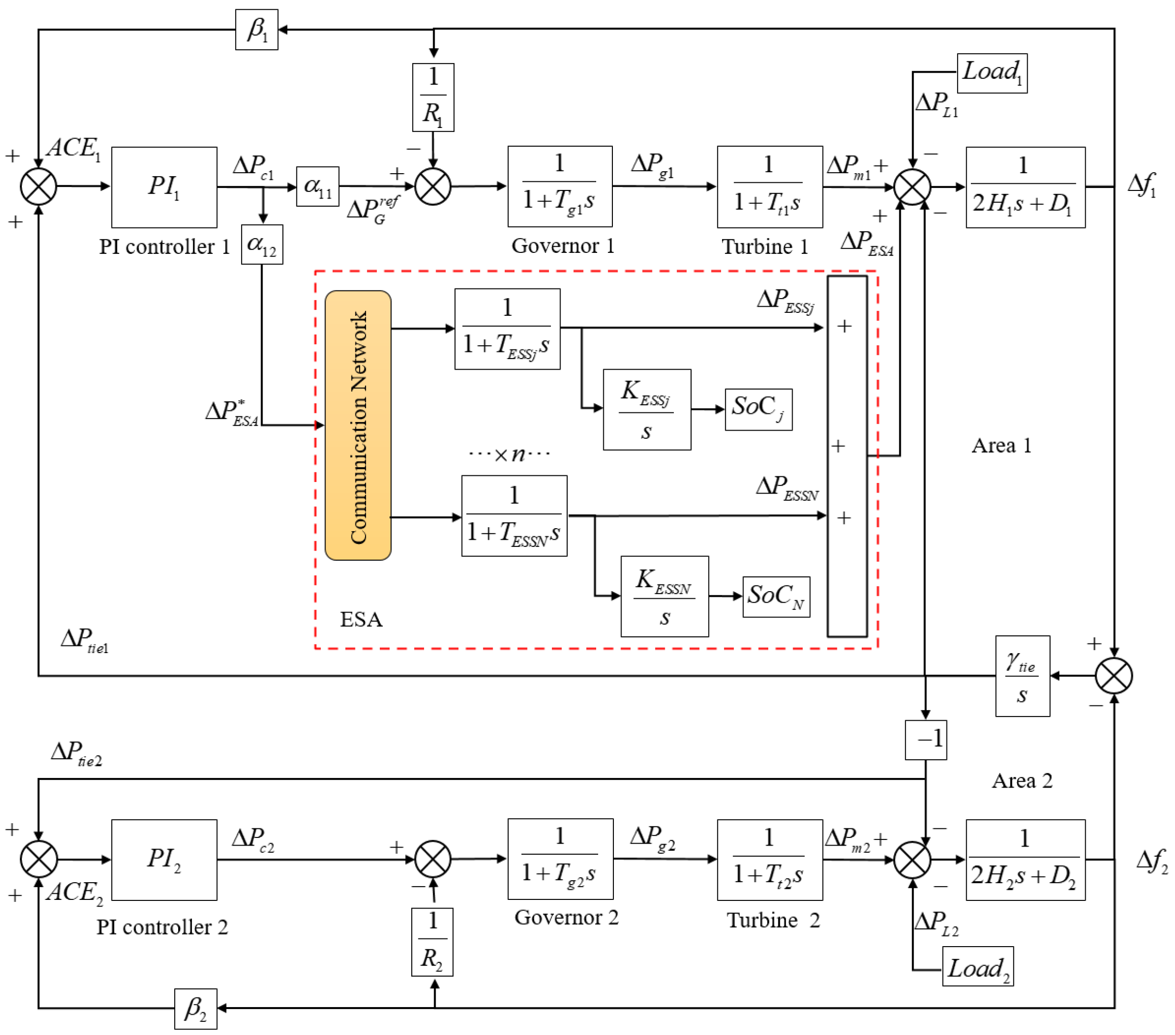
Figure 1. Equivalent model of two-area interconnected power system LFC with the ESA.
Processes 13 03669 g001
Figure 2. Load disturbance profile.
Processes 13 03669 g002
Figure 3. Communication network of the ESA.
Processes 13 03669 g003
Figure 4. Reward of the agent during training episodes.
Processes 13 03669 g004
Figure 5. Frequency deviation comparison of three control methods.
Processes 13 03669 g005
Figure 6. Frequency response under different load step disturbances. Note: Each subfigure in this figure is a zoomed-in view of the corresponding time intervals in Figure 5, specifically 170–200 s, 340–370 s, 500–530 s, and 690–720 s, respectively.
Processes 13 03669 g006
Figure 7. Mechanical power deviation comparison of three control methods.
Processes 13 03669 g007
Figure 8. ESS power output comparison under different control methods.
Processes 13 03669 g008
Figure 9. ESS SOC comparison under different control methods.
Processes 13 03669 g009
Figure 10. ACE comparison in two-area interconnected system.
Processes 13 03669 g010
Table 1. Parameters of the power system.
D i (pu/Hz) H i (s) R i (Hz/pu) T G , i (s) T T , i (s)
0.0150.08333.000.080.40
0.0160.10082.730.060.43
Table 2. Parameters of different types of ESSs.
ESS T ESS (s) E ESS max (p.u.·h) [ P ESS min , P ESS max ] (p.u.) [ S ESS min , S ESS max ]
SCES0.0050.0025 [ 0.002 , 0.002 ] [ 0.3 , 0.7 ]
VRFBES0.0400.0040 [ 0.003 , 0.003 ] [ 0.3 , 0.7 ]
LABES1.0000.0065 [ 0.005 , 0.005 ] [ 0.3 , 0.7 ]
LIPBES0.0200.0015 [ 0.001 , 0.001 ] [ 0.3 , 0.7 ]
Table 3. Performance metrics comparison.
MetricTraditional PIDLeader–FollowerThe Proposed
Maximum Frequency
Deviation (Hz)
0.03480.03750.0260
Settling Time (s)0.94000.84300.7320
SoC Synchronization Time (s)Not Converged5.12905.1640
Average Control Effort (p.u.)0.00050.00080.0008
Maximum Generator Power
Deviation (p.u.)
0.02340.02210.0182
Frequency Regulation
Stability Index
0.16260.24640.0960
Disclaimer/Publisher’s Note: The statements, opinions and data contained in all publications are solely those of the individual author(s) and contributor(s) and not of MDPI and/or the editor(s). MDPI and/or the editor(s) disclaim responsibility for any injury to people or property resulting from any ideas, methods, instructions or products referred to in the content.