Article

Effect of Ignition Timing on Combustion and Emissions in a Downsized Rotary Engine Fueled with Methanol

1
School of Energy and Power Engineering, North University of China, Taiyuan 030051, China
2
School of Mechanical and Electrical Engineering, North University of China, Taiyuan 030051, China
3
Shanxi Diesel Engine Industry Co., Ltd., Datong 037036, China
*
Authors to whom correspondence should be addressed.
Processes 2025, 13(11), 3565; https://doi.org/10.3390/pr13113565
Submission received: 1 October 2025 / Revised: 18 October 2025 / Accepted: 28 October 2025 / Published: 5 November 2025

Abstract

The downsized Wankel rotary engine (WRE) fueled with methanol is a promising power source for small unmanned aerial vehicles, owing to its simple structure, high-speed capability, and clean emissions. In general, a well-designed ignition timing (IT) can drastically enhance engine combustion performance. To assess the impact of IT, a numerical simulation study was conducted on a methanol-fueled WRE, analyzing its combustion characteristics and emissions to guide performance optimization. The results indicated that advancing the IT boosted the flame propagation velocity. The peak pressure increased slightly when delaying the IT from −24 °CA to −15 °CA but dropped sharply for −12 °CA at 5000 RPM. This contrasts with the behavior at 11,000 RPM and 17,000 RPM, where peak pressure clearly rose with advanced IT. Indicated thermal efficiency (ITE) decreased with the delay of the IT at 11,000 RPM and 17,000 RPM; the maximum values reached 24.98% and 25.78%, respectively. This contrasted with the trend observed at 5000 RPM, where ITE first increased and then decreased with IT delay. The optimized IT significantly affects pollutant emissions primarily under low-speed conditions (5000 RPM), while exhibiting limited impact at high engine speeds. At 5000 RPM, strategic IT adjustment achieves maximum reductions of 2% in CO emissions and 33% in formaldehyde emissions.

1. Introduction

Compared to a traditional reciprocating engine, the Wankel rotary engine (WRE) has the advantages of high-speed capability, a simple structure, easy miniaturization, low noise, and stable operation [1,2,3,4]. Furthermore, the WRE has a higher power density [5] and high-speed stability. Therefore, downsized WREs have broad application potential in small-scale unmanned aerial vehicles, small power generation equipment, and power equipment for range extenders [6,7]. However, it also has clear disadvantages. Due to the narrow recess chamber, large surface-to-volume (S/V) ratio, and top-line sealing structure [8], WREs encounter issues in organizing the flame combustion process, reducing severe cooling losses [9], and preventing leaks. That leads to some questions about their weaknesses, such as high fuel consumption, poor emission performance, serious leakage, and wear of sealing components [10,11]. In recent years, researchers interested in WREs have looked for ways to solve these problems. Fan et al. [12] and Warren et al. [13] improved the sealing problem encountered in WREs by designing a new type of sealing sheet and designing REs from the apex seal profile, respectively. Zhang et al. indicated that adopting a diamond-like carbon (DLC) coating improved friction and wear problems and improved the power of the downsized WRE by 24–43% [14]. Shi et al. [15] enhanced the combustion performance of WREs using a twin-plug ignition system. In addition, some new pilot ignition [16] and laser ignition [17] methods have been applied to WREs to improve combustion performance and reduce specific fuel consumption and pollutant emissions. Not only structural innovations but also fuel replacement has been applied to WREs to optimize engine performance. Philip et al. [18], Kamo et al. [19], Pan et al. [20], and Su et al. [21] studied natural gas-fueled, diesel-fueled, ethanol/gasoline-fueled, and n-butanol-fueled WREs, respectively. Furthermore, the performance of WREs was optimized and the pollutant emissions were reduced by adjusting the IT and injection duration.
Global warming is an indisputable fact. The increase in CO2 use has accelerated the speed of global warming and exerted a significant impact on human production and life [22]. Therefore, reducing carbon emissions has become an urgent issue. Methanol (CH3OH) has emerged as a promising alternative to gasoline and diesel, recognized for its renewability, economic viability, and environmental benefits in internal combustion engines (ICEs) [23]. The reasons for this are as follows: Firstly, methanol has large-scale production capacity and infrastructure in China, underpinning a robust application market [24]. Secondly, methanol offers significant logistical advantages as it remains in a liquid state at ambient conditions, enabling easy storage and transportation with minimal losses [25]. Thirdly, methanol can be derived from a variety of sources, contributing to its cost-effective production [26]. Therefore, methanol has been widely studied as a pure fuel or a blend fuel in ICEs. Celik et al. [23] explored the impacts of pure methanol on the performance and emissions of an ICE with a high compression ratio (CR), and found that compared to gasoline, NOx emissions dropped by 35% and thermal efficiency (TE) was enhanced by 16%. El-Emam et al. [27] indicated that using pure methanol can raise the TE and reduce emissions for spark-ignition (SI) engines. Research by Wouters et al. [28,29] and Vancoillie et al. [30] also showed similar results. In addition, An et al. [31] briefly explored the influence of methanol addition (5%, 10%, and 15% in volume) on the combustion of a diesel engine using numerical simulation, and found a linear relationship between increasing the methanol blend ratio and the increase in indicated thermal efficiency (ITE). Previous research demonstrates that methanol addition in small SI engines enhances combustion. One study found that 15% and 25% methanol blends improved combustion completeness and reduced cycle variability [32]. Another reported increased BTE along with shorter flame development and propagation periods compared to gasoline [33]. Furthermore, studies have extended to other methanol mixtures, such as with hydrogen, natural gas, and water, for use in ICEs.
However, methanol can also be used in WREs because it may compensate for some inherent drawbacks of this engine type. (1) The unidirectional flow in WREs impedes flame propagation toward the rear zone of the recess chamber. Nevertheless, the higher laminar flame speed of methanol prevents unburned zones by allowing the flame to propagate effectively against the unidirectional flow toward the trailing side. (2) The wide flammability limit of methanol can ensure the smooth formation of flame kernels with poor gas exchange and high residual gas ratios in the spark holes in WREs. (3) Methanol’s high octane number grants it strong anti-knock ability. This property allows for a higher compression ratio in WREs, thereby increasing thermal efficiency and improving fuel economy. (4) Methanol’s low heating value is approximately 45% that of gasoline and 46% that of diesel [34]. To maintain engine power, fuel supply must be increased; however, the WRE can effectively compensate for this shortcoming. (5) The high latent heat from methanol vaporization allows a denser fuel–air charge [35], which means it may increase engine volumetric efficiency and thus increase the power of the WRE. (6) The low adiabatic flame temperature of methanol–air combustion can result in lower wall heat loss and lower nitrogen oxide emissions [25]. In summary, methanol and WRE have a good complementarity. However, after a survey of the literature, few studies were found on the performance of the downsized methanol WRE. Therefore, the application of methanol fuel in small WREs remains to be studied.
Ignition optimization represents a fundamental approach to achieving superior combustion performance in engine design [36,37]. Ignition timing (IT) is a significant parameter of the engine operation [38]. Su et al. [39] investigated the impact of IT on the performance of a hydrogen–gasoline dual-fuel WRE using experimental methods, and found that the flame development period and in-cylinder temperature were reduced with the increase in IT. Yang et al. [40] examined the impacts of IT on a hydrogen WRE under low speed; their results showed that as the IT was delayed, the initial heat-releasing stage was first shortened and then lengthened and both HC and NO emissions were reduced. In the process of optimizing the ignition system for WREs, Jiao et al. [41] found that while a larger ignition advance angle improves engine performance, it comes at the cost of increased in-cylinder temperature and NOx emissions. In addition to experiments exploring the impact of ignition parameters on the performance of ICEs, numerical simulation technology has also been applied to explore engine performance. Wang et al. [42] examined the influences of IT on the combustion of an ammonia–hydrogen WRE through 3-D numerical simulation, and found that with IT delay, the combustion efficiency of the WRE was improved, and the max heat release rate (HRR) and flame propagation first increased and then decreased. Shi et al. [15] numerically examined the ignition amelioration of a hydrogen-enriched WRE, and their results indicated that asynchronous ignition readily improved flame development and combustion rate. Additionally, the leading plug initiated ignition earlier, accelerating flame propagation speed to deliver higher pressure and superior heat dissipation. Recently, Chang et al. [43] found that the trailing plug ignites early, accelerating the combustion process, while premature ignition at the leading plug causes the flame front to become irregular. The above research shows that the IT exhibits a great impact on the combustion and emissions by influencing the formation and development of flame in the SI WRE.
Considering that methanol fuel can be adapted to downsized WREs to a certain extent and there are few studies on pure methanol-fueled WRE, this study aims to address this gap in the literature. For this, a computational fluid dynamics (CFD) model of the WRE fueled with methanol was developed, selecting a reasonable turbulence combustion model and simplifying the mechanism of methanol, and its reliability was confirmed by comparing its predictions with test results. First, the influence of IT on the flame propagation was investigated using the simulation model. Secondly, the effects of IT on combustion performance were studied. Finally, emissions during operation of the WRE were explored. The performance of the pure methanol WRE was optimized by adjusting the IT over different engine speeds. The findings from this research are intended to directly aid in the optimization of combustion and emissions for a downsized methanol-fueled WRE.

2. Establishment and Verification of Mathematical Mode

2.1. Geometric Model and Boundary Condition Setting

Based on Creo 5.0 software, a fluid domain model of the OS49II WRE is constructed with the peripheral intake and exhaust port, three chambers, and one plug chamber, as illustrated in Figure 1. It is worth noting that this simulation model accounts for cross-leakage effects between adjacent chambers but disregards external leakage. The relevant parameters of the test WRE are listed in Table 1. The operating process of the WRE includes intake, compression, power, and exhaust, and each operating process accounts for 270 °CA. Additionally, the structure and operating process of the three chambers are similar, resulting in consistency across the combustion processes in the three chambers. Therefore, the combustion inside chamber II is calculated for the analysis, which is the method commonly used to study the WRE [15,44].
In addition, the simulation model boundaries of the inlet, the outlet, and all walls are shown in Table 2. In the current study, the wall temperatures of intake port, exhaust port, and cylinders are determined through experimental bench measurements. Since the rotor and spark plugs are installed inside the combustion chamber, direct measurement is not feasible. Therefore, their temperatures are reasonably estimated based on the temperatures of the components they come into contact with and published data from the literature. Published studies indicate a temperature range of 400–750 K for the rotor wall and plug wall [41,45,46].

2.2. Mathematical Models and Meshing

In the current study, CONVERGE 3.0 software is employed to calculate the combustion inside the cylinder of the WRE. There are complex vortex flows in the cylinder of the WRE; thus, the RNG k-ε model was chosen to calculate the flow field. This model has been shown to accurately capture in-cylinder vortex flow variations, as it accounts for factors such as streamline curvature, tumble, and swirl [47,48]. The SAGE model was chosen to compute the reaction rate of each element reaction in the combustion mechanism. The SAGE model is a general combustion model that facilitates evaluation of the combustion process [49]. Meanwhile, the skeletal mechanism developed by Li et al. [50], encompassing 21 species and 84 reactions, was employed to compute the chemical reaction and heat release of the surrogate fuel. The accuracy of applying this mechanism to other rotary engines has been validated in a published study [45].
In addition, as for the ignition model, the primary target of the current study is to examine the impact of IT on the combustion of the WRE at different speeds, while ignoring the internal structure of the spark plug. According to the distance between the cathode and anode and discharge energy of the actual spark plug in the experiment, the ignition was modeled as a hypothetical spherical flame kernel with a radius of 0.3 mm and an energy of 0.02 J, representing the physical spark plug that initiates chemical reactions in the chamber. When solving computational fluid dynamics problems, not only the accuracy and convergence of the mathematical models of the above-mentioned physical and chemical processes but also the basic quantity and quality of the grid affect the precision of the results [47]. To obtain faster and more accurate calculation results, the base grid size is set to 2 mm, with the fluid domain employing 3 levels of AMR (Adaptive Mesh Refinement) based on temperature and velocity variations. The relation between grid size and refinement level is presented in Equation (1). Furthermore, a 3-level fixed embedding is carried out during ignition.
d = d b a s e 2 n
where d and d b a s e represent grid size and basic grid size, respectively. n is refined level. Following the grid refinement criteria, the minimum grid size is 0.25 mm. This represents the smallest length scale (0.1~1 mm) required to satisfy the simulation needs of typical engines using a RANS model [51]. The final cell counts during computation ranged from 40,000 to 83,250 per chamber. Additionally, the PISO method was employed to solve the Navier–Stokes equations in this study, with tolerance set to 1 × 10⁻³ s. Meanwhile, the minimum time-step was set to 1 × 10⁻⁸ s, and the maximum time-step was 1 × 10⁻⁴ s.

2.3. Scheme Design

In this paper, the engine speed condition is studied at 5000 RPM, 11,000 RPM, and 17,000 RPM, respectively. To explore the impact of IT on the combustion and emissions of the downsized methanol WRE, IT schemes of −12 °CA, −15 °CA, −18 °CA, −21 °CA, and −24 °CA are applied at all three engine speeds. For all computing schemes, the working conditions are an excess air ratio (φ) of 1.15 and a Wide Open Throttle (WOT).

2.4. Model Validation and Calibration

A schematic diagram of the test bench for the downsized WRE is displayed in Figure 2. A commercial OS49II methanol-fueled WRE was used for this experiment. Engine experiments were conducted at the Magtrol dynamometer Dsp 7000 test facility. To measure the pressure, a 6052CU20 Kistler pressure sensor was employed in this work. The sensor signal was amplified using a 996A27 Kistler charge amplifier.
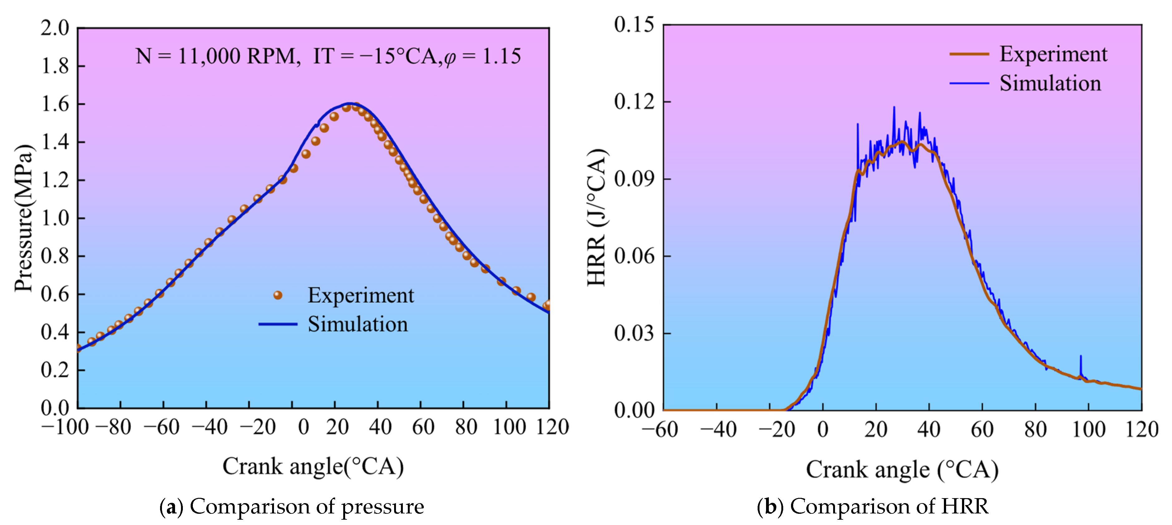
To guarantee the calculation precision of the simulation model developed in this study, the in-cylinder pressure was compared between the measured and predicted model under the same working conditions. Experimental conditions were set as follows: the engine speed (N) was 11,000 RPM; φ = 1.15; IT = −15 °CA; and WOT. The test pressure is the averaged values of 5 cycle test results, while the simulation data represents in-cylinder pressure results up to the third cycle of engine operation. A comparison of the simulated and experimental results is displayed in Figure 3, in which can find a slight positive discrepancy in pressure between the simulation and experiment during the combustion phase. The reasons for this are as follows: (1) The current simulation model does not account for leakage. (2) The skeletal mechanism of methanol cannot completely simulate the actual combustion process. However, the errors between the simulation and the experiment are less than 5% from the overall trend, and the trends in HRR observed from the experiments and simulations show good agreement. This means that the CFD simulation model can accurately predict the combustion process of the WRE.

3. Results and Discussion

3.1. Impact of IT on Flame Propagation

One of disadvantages of the WRE is that it is difficult to organize the combustion process because of the narrow recess chamber and high speed. The formation and development of the early flame kernel play a crucial role. Therefore, it is important to study how flames propagate within the cylinder. Figure 4 shows the distribution of flame front and turbulent kinetic energy (TKE) under varying ITs. It can be seen that a complete flame kernel is formed inside the chamber under all ignition conditions. As the flame propagates, the flame front continues to expand in the leading side of the chamber, but the trailing side hardly expands. This is due to the fact that the rotor motion is unidirectional in the WRE, resulting in a unidirectional flow field in the chamber, thereby expediting the flame front to expand to the leading side of the chamber and retarding the flame propagation in the opposite direction of rotor rotation. For all engine speeds, the spread range of the flame front is increased with IT. This is because an earlier IT causes the flame kernel to form earlier and the flame front to develop later. However, at 16 °CA ATDC, the difference in flame front is smaller, which indicates that the flame propagation speed is elevated as the IT is delayed. It can be also seen in Figure 4 that at an IT of −24 °CA, the flame front at 5000 RPM has developed to the combustion chamber wall, but that at 17,000 RPM has a certain space from the combustion chamber wall. That indicates that the higher the engine speed, the more delayed the combustion and the longer the duration of combustion due to the influence of turbulence in the chamber. According to the TKE distribution within the combustion chamber, the TKE increases with rising engine speed. The increased in-cylinder turbulence intensity leads to a non-uniform distribution of the methanol–air mixture, resulting in decreased mixture concentration at the flame front under the same crank angle and consequently slowing down flame development. This is in agreement with the results reported by Yang et al. [52].

3.2. Impact of IT on Combustion Characteristics

Engine performance is critically influenced by the flame development and propagation periods, which are key metrics of combustion characteristics. The flame development period (CA 0–10) in this paper was taken as the duration between the IT and the crank angle with 10% cumulative heat release [53]. Figure 5 shows the impact of IT on the flame development and propagation periods at different speeds. The flame development period is extended with the increase in engine speed under the same IT condition. That indicates that the higher the engine speed, the longer the flame development period. The reasons for this are as follows: Firstly, a higher TKE reduces the mixture concentration in front of the flame front, which decreases the flame development velocity and raises the flame development period. Secondly, the combustion in the WRE is retarded with an increase in engine speed. The flame development period is decreased with the delay of IT at the same engine speed. The shortest flame development period is obtained when ignited at −12 °CA, where the value is about 15%, 8%, and 6% shorter than the longest flame development period at −24 °CA at 5000 RPM, 11,000 RPM, and 17,000 RPM, respectively. This means that a delayed IT shortens the flame formation stage because it compresses this phase nearer to the TDC. At this position, the higher pressure and temperature create a more favorable thermal environment for flame kernel development [54].
The flame propagation period (CA10–90), defined as the crank angle interval from 10% to 90% of cumulative heat release, represents the primary combustion phase during which the bulk of the fuel is burned. It can be concluded from Figure 5b that the flame propagation period is less affected by IT at high speeds, which indicates that the turbulence intensity generated in the cylinder is the primary factor influencing the speed of flame propagation at high engine speeds. However, IT has a great effect on the flame propagation period at low speeds, especially after −21 °CA. For example, the flame development period is shortened by 13% with the IT delay from −21 °CA to −15 °CA. It is worth mentioning that at 5000 RPM, the flame propagation period first decreases and then increases with the delay of IT, reaching the minimum at −15 °CA. This is because as ignition is delayed, the combustion chamber volume decreases and the unburned mixture content increases, thereby providing a suitable environment for flame propagation. Therefore, the flame combustion velocity is accelerated, and the flame propagation period is shortened. However, when ignition occurs at −12 °CA, the mixture concentration further rises, leading to a reduction in the oxygen content in the mixtures and thereby reducing the flame burning rate and increasing the rapid combustion period. OH is an intermediate product of the combustion of methanol fuel, existing in the form of hydroxyl radicals, which can reflect the distribution of the flame. Figure 6 shows that the OH content aligns with the trend of the flame propagation period at the corresponding time points. At −24 °CA and −21 °CA, the flame propagation period is longer at 5000 RPM than at 11,000 RPM, which is mainly because the faster flame propagation causes the flame to come into contact with the chamber wall earlier and quenching occurs, inhibiting further flame expansion. At 17,000 RPM, however, the flame development period over the same IT is always the largest, implying that the turbulence intensity has a significant effect under high-speed conditions. As shown in Figure 6b, the turbulence intensity is the highest at 17,000 RPM, causing combustion lag and prolonging the flame propagation period.
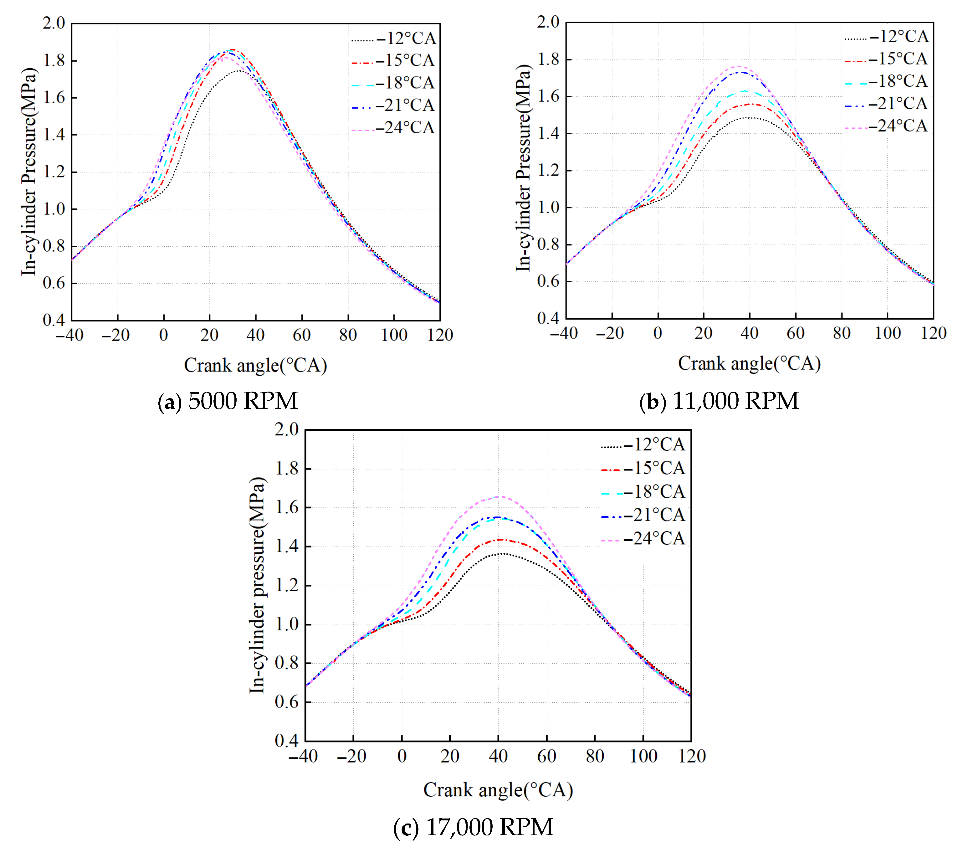
Figure 7 displays the curves of in-cylinder pressure at varying IT levels and engine speeds. The max pressure increases slightly with retarding IT from −24 °CA to −15 °CA, but drops sharply at −12 °CA at 5000 RPM. The reasons for this are as follows: Firstly, the lower turbulence intensity in the combustion chamber at low speeds is less restrictive to the flame development. Secondly, with the delay of the IT, the flame propagation velocity increases and the flame propagation period decreases, causing the heat to be released in a short period, and thus increasing the peak pressure. However, at IT = −12 °CA, HRR is still lower around TDC, causing the flame propagation period to increase and leading to a reduction in pressure. At 11,000 RPM and 17,000 RPM, the max pressure is elevated dramatically with an increase in the IT, which is contrary to the trend of max pressure achieved at 5000 RPM. Retarding the IT shifts the crank angle for max pressure to after TDC across all engine speeds. However, the magnitude of this shift diminishes at higher speeds. For instance, when the IT is changed from −24 °CA to −12 °CA, the location of max pressure is delayed by 3.1 °CA at 5000 RPM, but only by 0.7 °CA at 17,000 RPM. In addition, the max pressure decreases as engine speed increases. At −15 °CA, the 1.86 MPa corresponding to 5000 RPM is 29% higher than the 1.44 MPa corresponding to 17,000 RPM, which is primarily due to the influence of turbulence (see Figure 6b).
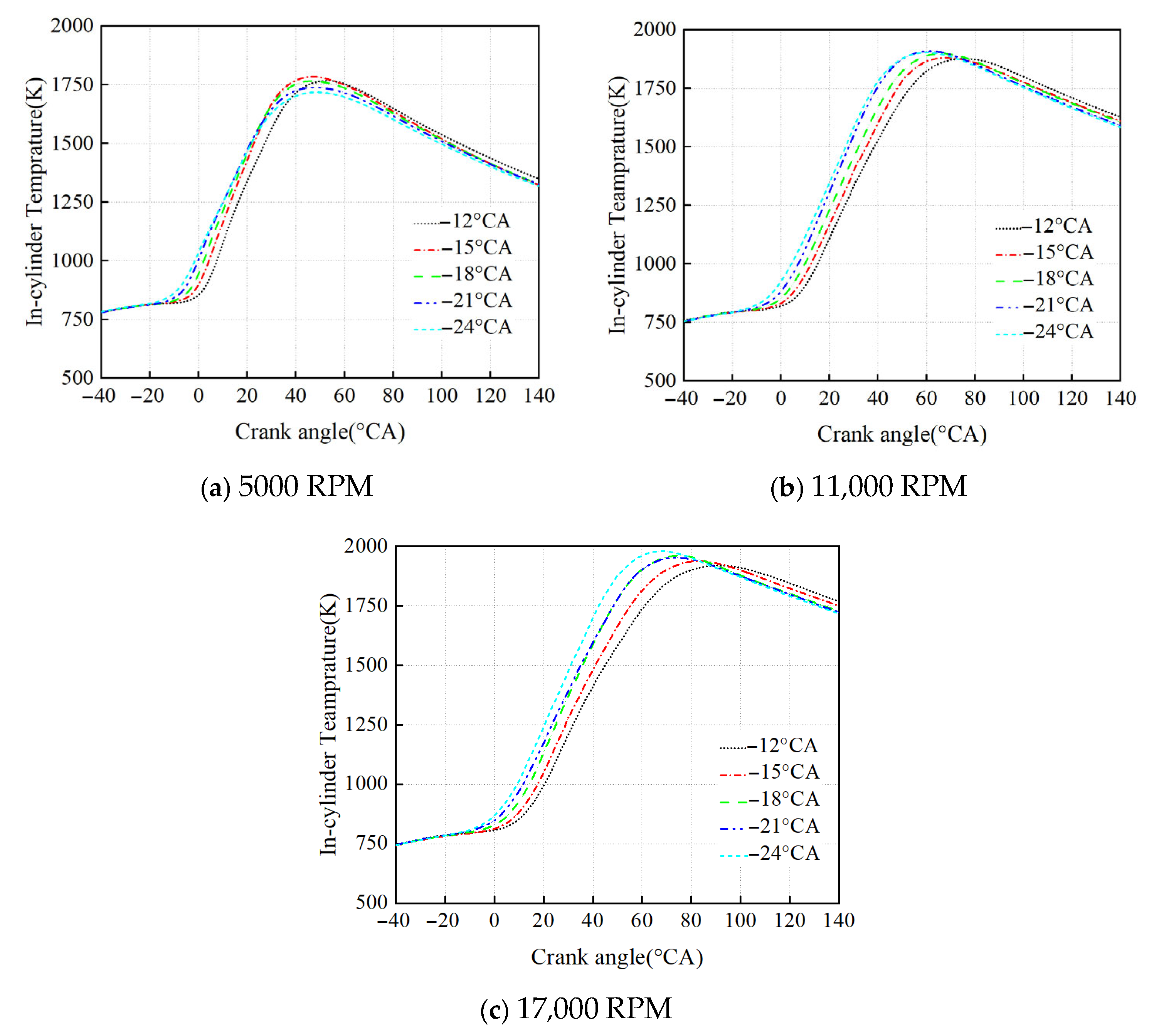
Figure 8 shows the impact of IT on combustion temperature over various engine speeds. As show in Figure 8a, at 5000 RPM, the max temperature first rises and then decreases as the IT is postponed. At 11,000 RPM and 17,000 RPM, however, the max temperature is decreased slightly as the IT is delayed. This can also be explained by the influence of the flame propagation period. Through the analysis above, it can be inferred that the crank angle corresponding to the max temperature can be advanced under high-speed conditions. At 5000 RPM, 11,000 RPM, and 17,000 RPM, the max temperatures occurred under the ITs of −15 °C, −24 °C, and −24 °C, respectively, with corresponding temperature values of 1785.1 K, 1908.1 K, and 1979.2 K. Compared to the minimum peak temperatures, these values increased by 3.8%, 1.6%, and 3.1%, respectively. This indicates that, for one, the optimal IT is increased with elevating engine speed for the downsized WRE; furthermore, the in-cylinder temperature shows a rising trend with enhancing engine speed at the same IT. It is noteworthy to mention that the max temperature can be increased from 1766 K to 1979 K by 12.1% at −24 °CA from 5000 RPM to 17,000 RPM, which has a much more noticeable improvement than adjusting the IT. This indicates that increasing the engine speed a greater influence on the temperature change than adjusting the IT. This is because as the engine speed rises, the influence of turbulence intensity on flame development gradually increases and excessive exhaust gas is present inside the chamber, resulting in higher in-cylinder temperatures.
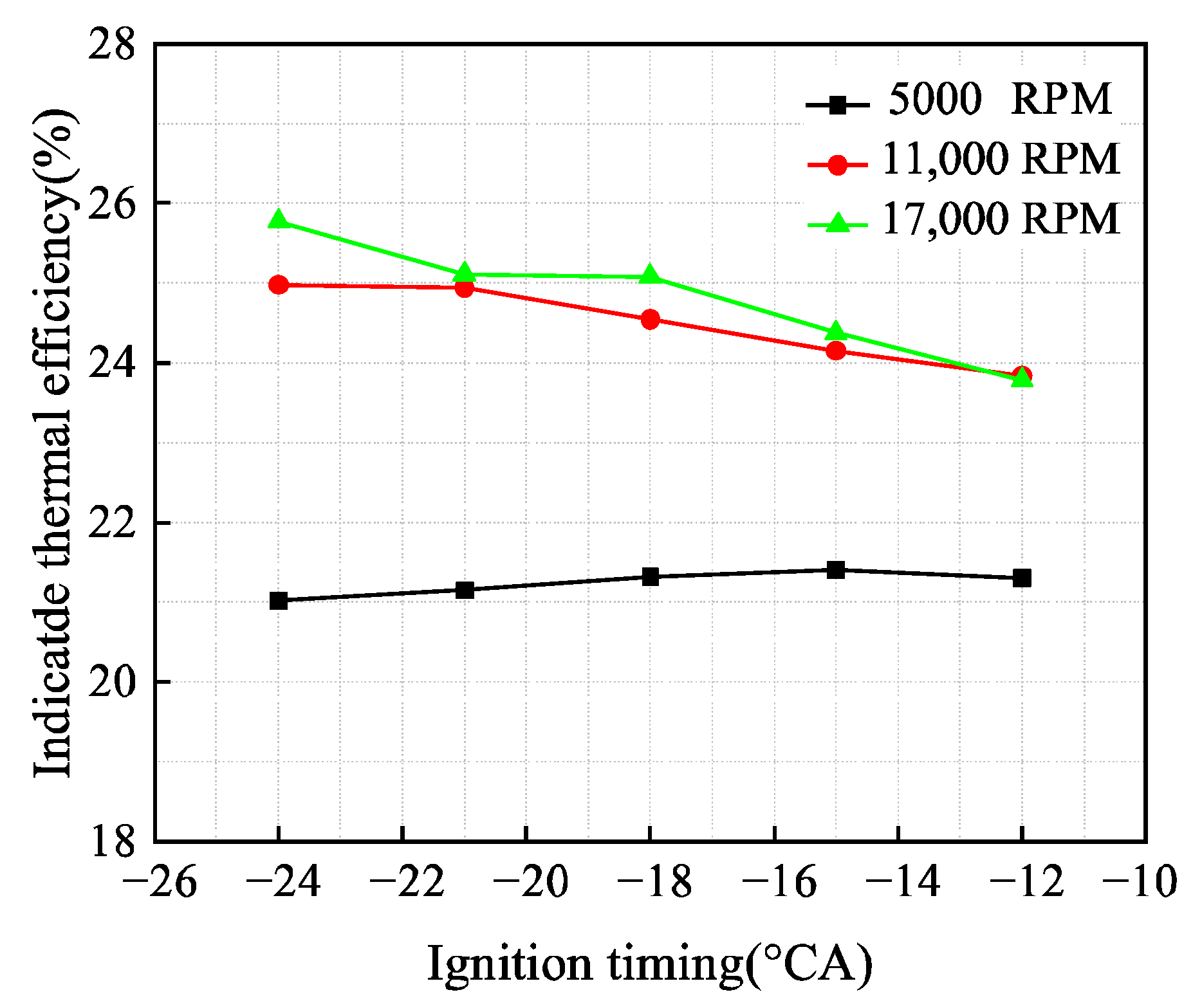
The ITE of an engine is a key metric in determining the performance of an automobile and its economics. Lim et al. [55] pointed out in their study that the IT has a certain influence on the ITE, which means that the ITE of the downsized WRE can be enhanced by improving the IT. Figure 9 plots the impact of IT on the ITE over various engine speeds. The ITE first rises and then decreases as the IT is retarded at 5000 RPM, and exhibits the best performance at the IT of −15 °CA, where it reaches 21.40%. This is symmetrical to the trend of the flame propagation period, indicating that the shorter the flame propagation time, the higher the ITE under low-speed conditions. At 11,000 RPM and 17,000 RPM, however, the ITE exhibits a declining trend when the IT is delayed. Under the IT of −24 °C, maximum values reach 24.98% and 25.78%, representing increases of 2% and 1.1%, respectively, compared to the IT of −15 °C. At 5000 RPM, however, the ITE improves by only 0.4%. This indicates that the effect of IT on ITE under high-speed conditions is greater than that at low-speed conditions. Combined with the variation trend of 5000 RPM, it can be inferred that the optimal IT of ITE at 11,000 RPM and 17,000 RPM can be achieved. Figure 9 also shows that the ITE at high speeds is greater than that at low speeds under the same IT. This is because the higher the engine speed, the shorter the period of a cycle, thus reducing the heat transfer loss of the wall and resulting in an increase in ITE. However, the ITE does not increase much above 11,000 RPM, which indicates that in addition to heat loss, the fuel combustion performance also affects the ITE.

3.3. Impact of IT on Emissions

Figure 10 illustrates the effects of IT on CO emissions at varying engine speeds. The results demonstrate that at 5000 RPM, CO emissions increase with retarding IT, with minimal variation observed beyond −24 °CA. The lowest CO emissions occur at −24 °CA, showing a 2% reduction compared to the maximum emissions at −12 °CA. At 11,000 RPM, CO emissions display a non-monotonic trend, first rising and then reducing with delays in the IT. Peak emissions occur at −21 °CA, while the minimum emissions are achieved at −12 °CA, representing a maximum reduction potential of 0.2% through IT optimization. For the engine speed of 17,000 RPM, CO emissions display a concave profile versus IT, reaching the lowest value at −21 °CA and peaking at −12 °CA. This corresponds to a maximum emission reduction of 0.55% through IT adjustment. CO emissions are drastically increased as the engine speed is boosted. These results conclusively demonstrate that the engine speed has a dominant influence on CO emission characteristics, with a 267% increase observed when the engine speed escalates from 5000 RPM to 17,000 RPM. In contrast, IT optimization provides limited mitigation effects, yielding emission reductions below 2% across all speed conditions.
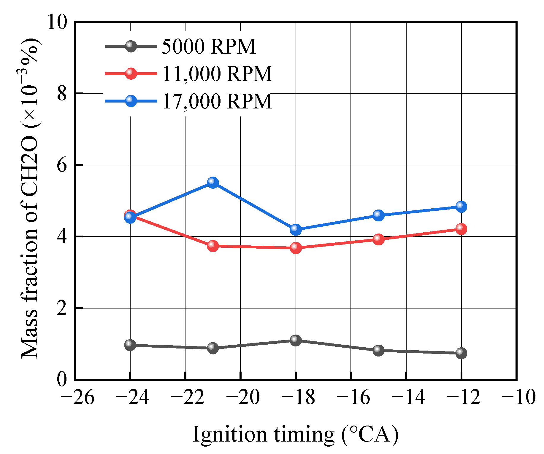
Figure 11 displays the influences of IT on formaldehyde (CH2O) emissions from the engine under different speeds. The results indicate that at 5000 RPM, formaldehyde emissions first elevate and then drop overall as the IT is delayed. The maximum emission occurs at −18 °CA, while the minimum is achieved at −12 °CA, representing a 33% reduction compared to the peak value. At 11,000 RPM, formaldehyde emissions first drop and then increase when the IT is delayed. The maximum emissions occur at −24 °CA, while the minimum is achieved at −18 °CA, showing a 22% reduction. When engine speed increases to 17,000 RPM, formaldehyde emissions show no clear linear relationship with IT in the range of −24 °CA to −12 °CA, instead exhibiting a trend of first elevating, then declining, and rising again. The highest emissions occur at −21 °CA, while the lowest appear at −18 °CA, representing a 23% reduction from the peak value. This demonstrates that formaldehyde emissions are primarily influenced by engine speed. As the engine speed is elevated from 5000 RPM to 11,000 RPM, the peak CH2O emissions increase by about 25 times compared to the minimum value, far exceeding the improvement achievable through IT optimization.
The analysis of the effect of IT on emission characteristics across different speeds shows that IT mainly affects CO emissions at low speeds, consistent with the combustion analysis above. The flame propagation period lengthens as engine speed increases, leading to severe combustion losses at high speeds. Both CO and formaldehyde emissions are primarily affected by whether fuel combustion is complete, and high-speed conditions are more likely to result in incomplete combustion. Therefore, as engine speed increases, CO and formaldehyde emissions increase accordingly. This shows that at low speeds, optimizing IT can reduce CO and formaldehyde emissions, while high-speed conditions require other emission reduction measures.

4. Conclusions

This study used numerical simulations to analyze the impact of IT on the combustion characteristics and emissions of the OS49II downsized WRE fueled with methanol at speeds of 5000 RPM, 11,000 RPM, and 17,000 RPM. The main findings resulting from this study are summarized as follows:
(1)
Propagation of the flame front in the leading side of the chamber is facilitated, but that in the trailing side is inhibited. Higher engine speeds prolong the duration of combustion. For a constant engine speed, a earlier IT elevates the flame propagation speed and the spread range of the flame front is larger.
(2)
The flame development period is extended with enhancing engine speed at the same IT. Delaying the IT shortens the flame formation stage. However, the IT exhibits a greater effect on the flame propagation period at low speeds, especially after −21 °CA, and the flame development period is shortened by 13% between −21 °CA and −15 °CA.
(3)
The max pressure increases slightly when delaying the IT from −24 °CA to −15 °CA but drops sharply at −12 °CA for 5000 RPM. Nevertheless, for 11,000 RPM and 17,000 RPM, the max pressure is enhanced remarkably with advancing the IT. At the same IT, the max pressure is dropped as the engine speed is elevated.
(4)
The ITE first rises and then drops as the IT is postponed at 5000 RPM and exhibits the best performance at −15 °CA, where the it reaches 21.40%. However, at 11,000 RPM and 17,000 RPM, the ITE decreases with the delay of the IT, and the maximum values can reach 24.98% and 25.78% at −24 °CA. Compared to the IT of −15 °CA, the ITE obtained at −24 °CA increased by 2% and 1.1%, respectively.
(5)
The optimized IT primarily demonstrates a significant effect on pollutant emissions under low-speed conditions (5000 RPM), while it exhibits limited impact at high engine speeds. At 5000 RPM, strategic IT adjustment achieves maximum reductions of 2% in CO emissions and 33% in formaldehyde emissions. With increasing engine speed, greater combustion losses occur, leading to dramatically elevated pollutant emissions under high-speed conditions. Compared to low-speed operation, the high-speed condition at 17,000 RPM exhibits maximum increases of 267% in CO emissions and a 25-fold increase in formaldehyde emissions.

Author Contributions

Conceptualization, Y.Z.; methodology, Y.Z.; software, L.L.; validation, L.L.; investigation, S.Y.; data curation, Y.Z.; writing—original draft, Y.Z.; writing—review and editing, T.H.; visualization, Y.L.; supervision, R.Z. All authors have read and agreed to the published version of the manuscript.

Funding

This work was supported by the Applied Basic Research Programs of Shanxi Province in China (Grant No. 202203021222045).

Data Availability Statement

The original contributions presented in this study are included in the article. Further inquiries can be directed to the corresponding authors.

Conflicts of Interest

Ting Hou was employed by Shanxi Diesel Engine Industry Co., Ltd. The remaining author declares that the research was conducted in the absence of any commercial or financial relationships that could be construed as potential conflicts of interest.

References

  1. Yang, J.; Meng, H.; Ji, C.; Wang, S. Comparatively investigating the leading and trailing spark plug on the hydrogen rotary engine. Fuel 2022, 308, 122005. [Google Scholar] [CrossRef]
  2. Fan, B.; Zeng, Y.; Zhang, Y.; Pan, J.; Yang, W.; Wang, Y. Research on the hydrogen injection strategy of a direct injection natural gas/hydrogen rotary engine considering apex seal leakage. Int. J. Hydrogen Energy 2021, 46, 9234–9251. [Google Scholar] [CrossRef]
  3. Cihan, Ö.; Doğan, H.E.; Kutlar, O.A.; Demirci, A.; Javadzadehkalkhoran, M. Evaluation of heat release and combustion analysis in spark ignition Wankel and reciprocating engine. Fuel 2020, 261, 116479. [Google Scholar] [CrossRef]
  4. Fan, B.; Zeng, Y.; Pan, J.; Fang, J.; Salami, H.A.; Wang, Y. Evaluation and analysis of injection strategy in a peripheral ported rotary engine fueled with natural gas/hydrogen blends under the action of apex seal leakage. Fuel 2022, 310, 122315. [Google Scholar] [CrossRef]
  5. Morris, N.; Hart, G.; Wong, Y.J.; Simpson, M.; Howell-Smith, S. Laser surface texturing of Wankel engine apex seals. Surf. Topogr. Metrol. Prop. 2020, 8, 034001. [Google Scholar] [CrossRef]
  6. Yang, J.; Ji, C.; Wang, S.; Zhang, Z.; Wang, D.; Ma, Z. Numerical investigation of the effects of hydrogen enrichment on combustion and emissions formation processes in a gasoline rotary engine. Energy Convers. Manag. 2017, 151, 136–146. [Google Scholar] [CrossRef]
  7. Cihan, Ö.; Akın, O. Effect of leading and trailing spark plugs on combustion, fuel consumption and exhaust emission in a Wankel engine. Arab. J. Sci. Eng. 2021, 46, 7471–7482. [Google Scholar] [CrossRef]
  8. Muroki, T.; Moriyoshi, Y.; Takagi, M.; Suzuki, K.; Imai, M. Research and Development of a Direct Injection Stratified Charge Rotary Engine with a Pilot Flame Ignition System; SAE Technical Paper 2001-01-1844; SAE International: Warrendale, PA, USA, 2001. [Google Scholar] [CrossRef]
  9. Rose, S.W.; Yang, D.C.H. Wide and multiple apex seals for the rotary engine: (Abbr.: Multi-apex-seals for the rotary engine). Mech. Mach. Theory 2014, 74, 202–215. [Google Scholar] [CrossRef]
  10. Amrouche, F.; Varnhagen, S.; Erickson, A.P.; Park, W.J. An experimental study of a hydrogen-enriched ethanol fueled Wankel rotary engine at ultra lean and full load conditions. Energy Convers. Manag. 2016, 123, 178–184. [Google Scholar] [CrossRef]
  11. Fan, B.; Zhang, Y.; Pan, Y.P.O. Experimental and numerical study on the formation mechanism of flow field in a side-ported rotary engine considering apex seal leakage. J. Energy Resour. Technol. 2020, 143, 22303. [Google Scholar] [CrossRef]
  12. Fan, B.; Pan, J.; Liu, Y.; Chen, W.; Lu, Y.; Otchere, P. Numerical investigation of mixture formation and combustion in a hydrogen direct injection plus natural gas port injection (HDI + NGPI) rotary engine. Int. J. Hydrogen Energy 2018, 43, 4632–4644. [Google Scholar] [CrossRef]
  13. Warren, S.; Yang, D.C.H. Design of rotary engines from the apex seal profile (Abbr.: Rotary engine design by apex seal). Mech. Mach. Theory 2013, 64, 200–209. [Google Scholar] [CrossRef]
  14. Zhang, S.; Liu, J.; Zhou, Y. Effect of DLC coating on the friction power loss between apex seal and housing in small Wankel rotary engine. Tribol. Int. 2019, 134, 365–371. [Google Scholar] [CrossRef]
  15. Shi, C.; Ji, C.; Ge, Y.; Wang, S.; Bao, J.; Yang, J. Numerical study on ignition amelioration of a hydrogen-enriched Wankel engine under lean-burn condition. Appl. Energy 2019, 255, 113800. [Google Scholar] [CrossRef]
  16. Muroki, T.; Moriyoshi, Y. Combustion characteristics of spark-ignition and pilot flame ignition systems in a model Wankel stratified charge engine. Proc. Inst. Mech. Eng. 2000, 214, 949–955. [Google Scholar] [CrossRef]
  17. Loktionov, E.Y.; Pasechnikov, N.A. First tests of laser ignition in Wankel engine. J. Phys. Conf. Ser. 2021, 1787, 12031. [Google Scholar] [CrossRef]
  18. Dimpelfeld, P.M.; MacK, J.R. Design and Testing of a Natural Gas Fueled 5.8 Liter Rotary Engine; SAE Technical Paper 920307; SAE International: Warrendale, PA, USA, 1992. [Google Scholar] [CrossRef]
  19. Kamo, P.; Yamada, T.Y.; Hamada, Y. Starting Low Compression Ratio Rotary Wankel Diesel Engine; SAE Technical Paper 870449; SAE International: Warrendale, PA, USA, 1987. [Google Scholar] [CrossRef]
  20. Pan, J.; Cheng, B.; Tao, J.; Fan, B.; Liu, Y.; Otchere, P. Experimental investigation on the effect of blending ethanol on combustion characteristic and idle performance in a gasoline rotary engine. J. Therm. Sci. 2021, 30, 1187–1198. [Google Scholar] [CrossRef]
  21. Su, T.; Ji, C.; Wang, S.; Cong, X.; Shi, L. Enhancing idle performance of an n-butanol rotary engine by hydrogen enrichment. Int. J. Hydrogen Energy 2018, 43, 6434–6442. [Google Scholar] [CrossRef]
  22. Jeffry, L.; Ong, M.Y.; Nomanbhay, S.; Mofijur, M.; Mubashir, M.; Show, P.L. Greenhouse gases utilization: A review. Fuel 2021, 301, 121017. [Google Scholar] [CrossRef]
  23. Celik, M.B.; Ozdalyan, B.; Alkan, F. The use of pure methanol as fuel at high compression ratio in a single cylinder gasoline engine. Fuel 2011, 90, 1591–1598. [Google Scholar] [CrossRef]
  24. Liu, J.; Ma, H.; Liang, W.; Yang, J.; Sun, P.; Wang, X.; Wang, Y.; Wang, P. Experimental investigation on combustion characteristics and influencing factors of PODE/methanol dual-fuel engine. Energy 2022, 260, 125131. [Google Scholar] [CrossRef]
  25. Verhelst, S.; Turner, J.W.G.; Sileghem, L.; Vancoillie, J. Methanol as a fuel for internal combustion engines. Prog. Energy Combust. Sci. 2019, 70, 43–88. [Google Scholar] [CrossRef]
  26. Zhen, X.; Wang, Y. An overview of methanol as an internal combustion engine fuel. Renew. Sustain. Energy Rev. 2015, 52, 477–493. [Google Scholar] [CrossRef]
  27. El-Amam, S.H.; Desoky, A.A. A study on the combustion of alternative fuels in spark-ignition engines. Int. J. Hydrogen Energy 1985, 10, 497–504. [Google Scholar] [CrossRef]
  28. Wouters, C.; Burkardt, P.; Fischer, M. Effects of stroke on spark-ignition combustion with gasoline and methanol. Int. J. Engine Res. 2022, 23, 804–815. [Google Scholar] [CrossRef]
  29. Wouters, C.; Lehrheuer, B.; Heuser, B.; Pischinger, S. Gasoline blends with methanol, ethanol and butanol. MTZ Worldw. 2020, 81, 16–21. [Google Scholar] [CrossRef]
  30. Vancoillie, J.; Demuynck, J.; Sileghem, L.; Verhelst, S. Comparison of the renewable transportation fuels, hydrogen and methanol formed from hydrogen, with gasoline–Engine efficiency study. Int. J. Hydrogen Energy 2012, 37, 9914–9924. [Google Scholar] [CrossRef]
  31. An, H.; Yang, W.M.; Li, J. Numerical modeling on a diesel engine fueled by biodiesel–methanol blends. Energy Convers. Manag. 2015, 93, 100–108. [Google Scholar] [CrossRef]
  32. Ni, P.; Wang, Z.; Wang, X.; Hou, L. Regulated and unregulated emissions from a non-road small gasoline engine fueled with gasoline and methanol-gasoline blends. Energy Sources Part A Recovery Util. Environ. Eff. 2014, 36, 1499–1506. [Google Scholar] [CrossRef]
  33. Wu, B.; Wang, L.; Shen, X.; Yan, R.; Dong, P. Comparison of lean burn characteristics of an SI engine fueled with methanol and gasoline under idle condition. Appl. Therm. Eng. 2016, 95, 264–270. [Google Scholar] [CrossRef]
  34. Tian, Z.; Wang, Y.; Zhen, X.; Liu, Z. The effect of methanol production and application in internal combustion engines on emissions in the context of carbon neutrality: A review. Fuel 2022, 320, 123902. [Google Scholar] [CrossRef]
  35. Black, F.M. Overview of the Technical Implications of Methanol and Ethanol as Highway Motor-Vehicle Fuels; SAE Technical Paper 912413; SAE International: Warrendale, PA, USA, 1991; pp. 1161–1190. [Google Scholar] [CrossRef]
  36. Gao, J.; Tian, G.; Ma, C.; Huang, L.; Xing, S. Explorations of the impacts on a hydrogen fuelled opposed rotary piston engine performance by IT under part load conditions. Int. J. Hydrogen Energy 2021, 46, 11994–12008. [Google Scholar] [CrossRef]
  37. Gong, C.; Li, Z.; Chen, Y.; Liu, J.; Liu, F.; Han, Y. Influence of ignition timing on combustion and emissions of a spark-ignition methanol engine with added hydrogen under lean-burn conditions. Fuel 2019, 235, 227–238. [Google Scholar] [CrossRef]
  38. Ji, C.; Liang, C.; Gao, B.; Wei, B.; Liu, X.; Zhu, Y. The cold start performance of a spark-ignited dimethyl ether engine. Energy 2013, 50, 187–193. [Google Scholar] [CrossRef]
  39. Su, T.; Ji, C.; Wang, S.; Shi, L.; Yang, J.; Cong, X. Effect of spark timing on performance of a hydrogen-gasoline rotary engine. Energy Convers. Manag. 2017, 148, 120–127. [Google Scholar] [CrossRef]
  40. Yang, J.; Ji, C.; Wang, S.; Meng, H. An experimental study on ignition timing of hydrogen Wankel rotary engine. Int. J. Hydrogen Energy 2022, 47, 17468–17478. [Google Scholar] [CrossRef]
  41. Jiao, H.; Zou, R.; Wang, N.; Luo, B.; Pan, W.; Liu, J. Optimization design of the ignition system for Wankel rotary engine considering ignition environment, flow, and combustion. Appl. Therm. Eng. 2022, 201, 117713. [Google Scholar] [CrossRef]
  42. Wang, S.; Sun, Y.; Yang, J.; Wang, H. Effect of excess air ratio and ignition timing on the combustion and emission characteristics of the ammonia-hydrogen Wankel rotary engine. Energy 2024, 302, 131779. [Google Scholar] [CrossRef]
  43. Chang, K.; Ji, C.; Wang, S.; Yang, J.; Wang, H.; Meng, H.; Liu, D. Numerical investigation of the synchronous and asynchronous changes of ignition timing in a double spark plugs direct injection rotary engine. Energy 2023, 268, 126688. [Google Scholar] [CrossRef]
  44. Zou, R.; Li, F.; Liu, J.; Yang, W.; Lei, L.; Zhang, L. Effect of ignition timing on combustion characteristics and emissions of an X-type rotary engine with the high efficiency hybrid cycle. Fuel 2025, 380, 133250. [Google Scholar] [CrossRef]
  45. Fan, B.; Li, W.; Zeng, Y.; Fan, M.; Yang, H.; Pan, J.; Zhang, Y.; Jiang, C. The coupling effect of turbulent jet ignition and injection strategy on the combustion performance of a pure methanol rotary engine. Appl. Therm. Eng. 2025, 258, 124544. [Google Scholar] [CrossRef]
  46. Ji, C.; Shi, C.; Wang, S.; Yang, J.; Su, T.; Wang, D. Effect of dual-spark plug arrangements on ignition and combustion processes of a gasoline rotary engine with hydrogen direct-injection enrichment. Energy Convers. Manag. 2019, 181, 372–381. [Google Scholar] [CrossRef]
  47. Otchere, P.; Pan, J.; Fan, B.; Chen, W.; Lu, Y.; Li, J. Mixture formation and combustion process of a biodiesel fueled direct injection rotary engine (DIRE) considering injection timing, spark timing and equivalence ratio–CFD study. Energy Convers. Manag. 2020, 217, 112948. [Google Scholar] [CrossRef]
  48. Fan, B.; Pan, J.; Tang, A.; Pan, Z.; Zhu, Y.; Xue, H. Experimental and numerical investigation of the fluid flow in a side-ported rotary engine. Energy Convers. Manag. 2015, 95, 385–397. [Google Scholar] [CrossRef]
  49. Spreitzer, J.; Zahradnik, F.; Geringer, B. Implementation of a Rotary Engine (Wankel Engine) in a CFD Simulation Tool with Special Emphasis on Combustion and Flow Phenomena; SAE Technical Paper 2015-01-0382; SAE International: Warrendale, PA, USA, 2015. [Google Scholar] [CrossRef]
  50. Li, J.; Zhao, Z.; Kazakov, A.; Chaos, M.; Dryer, F. A comprehensive kinetic mechanism for CO, CH2O, and CH3OH combustion. Int. J. Chem. Kinet. 2010, 39, 109–136. [Google Scholar] [CrossRef]
  51. Pomraning, E.; Richards, K.; Senecal, P. Modeling Turbulent Combustion Using a RANS Model, Detailed Chemistry, and Adaptive Mesh Refinement; SAE Technical Paper 2014-01-1116; SAE International: Warrendale, PA, USA, 2014. [Google Scholar] [CrossRef]
  52. Yang, J.; Wang, H.; Ji, C.; Chang, K.; Wang, S. Investigation of intake closing timing on the flow field and combustion process in a small-scaled Wankel rotary engine under various engine speeds designed for the UAV application. Energy 2023, 273, 127147. [Google Scholar] [CrossRef]
  53. Ji, C.; Wang, S. Effect of hydrogen addition on combustion and emissions performance of a spark ignition gasoline engine at lean conditions. Int. J. Hydrogen Energy 2009, 34, 7823–7834. [Google Scholar] [CrossRef]
  54. Deshaies, B.; Joulin, G. On the initiation of a spherical flame kernel. Combust. Sci. Technol. 1984, 37, 99–116. [Google Scholar] [CrossRef]
  55. Lim, G.; Lee, S.; Park, C.; Choi, Y.; Kim, C. Effect of ignition timing retard strategy on NOx reduction in hydrogen-compressed natural gas blend engine with increased compression ratio. Int. J. Hydrogen Energy 2014, 39, 2399–2408. [Google Scholar] [CrossRef]
Figure 1. Fluid domain model of the test WRE.
Processes 13 03565 g001
Figure 2. Schematic diagram of the test bench (1. downsized WRE, 2. pressure transducer, 3. torque sensor, 4. dynamometer, 5. clutch, 6. generator, 7. dynamometer controller, 8. generator controller).
Processes 13 03565 g002
Figure 3. Comparison of simulation and experimental results.
Processes 13 03565 g003
Figure 4. Evolution of flame front and TKE in the cylinder under varying crank angles.
Processes 13 03565 g004
Figure 5. The effect of IT on flame development and propagation periods over different speeds.
Processes 13 03565 g005
Figure 6. The effect of IT on OH and TKE at varying engine speeds.
Processes 13 03565 g006
Figure 7. Impact of IT on in-cylinder pressure at different engine speeds.
Processes 13 03565 g007
Figure 8. Impact of IT on combustion temperature over different engine speeds.
Processes 13 03565 g008
Figure 9. Impact of IT on ITE under varying speed conditions.
Processes 13 03565 g009
Figure 10. Effect of IT on CO emissions under various engine speeds.
Processes 13 03565 g010
Figure 11. Impact of IT on CH2O emissions under various engine speeds.
Processes 13 03565 g011
Table 1. Relevant parameters of the OS49II WRE.
ParametersValues
Rated speed/RPM17,000
Displacement/mm4970
Compression ratio8.5
Generating radius/mm21
Eccentricity/mm3
Cylinder thickness/mm14.5
FuelMethanol
Number of rotors1
Table 2. Boundary conditions.
Boundary RegionBoundary TypeTemperature (K)Pressure (Bar)
InletInflow3200.61
OutletOutflow8001.01
Intake portFixed wall330
Exhaust portFixed wall550
Rotor wallMoving wall520
Cylinder sidesFixed wall550
Cylinder topFixed wall550
Cylinder bottomFixed wall550
Plug wallFixed wall550
Disclaimer/Publisher’s Note: The statements, opinions and data contained in all publications are solely those of the individual author(s) and contributor(s) and not of MDPI and/or the editor(s). MDPI and/or the editor(s) disclaim responsibility for any injury to people or property resulting from any ideas, methods, instructions or products referred to in the content.