Abstract
In recent years, renewable energy generation (RPG) has experienced rapid growth, and large-scale hydro–wind–photovoltaic storage (HWPS) bases have been progressively developed in southwest China, where hydropower resources are abundant. Ensuring the small-signal stability of such large-scale integrated systems has become a critical challenge. While considerable research has focused on the small-signal stability of grid-connected wind, photovoltaic, or energy storage systems (ESSs), studies on the stability of large-scale HWPS bases remain limited. Moreover, emerging grid codes require power electronic devices to maintain synchronization under unbalanced grid conditions. The time-varying rotating transformations introduced by positive-sequence (PS) and negative-sequence (NS) control render the conventional Park transformation ineffective. To address these challenges, this study develops a linear time-periodic (LTP) model of a large-scale HWPS base using trajectory linearization. Based on Floquet theory, the impacts of RPG station and ESS control parameters on system stability are analyzed. The results reveal that under the considered scenario, these control parameters may induce oscillations over a relatively wide frequency range. Specifically, low PLL and DVC bandwidths (BWs) are associated with the risk of low-frequency oscillations, whereas excessively high BWs may lead to sub-synchronous oscillations. The validity of the analysis is verified through comparison with time-domain simulations of the nonlinear model.
1. Introduction
Renewable energy generation, particularly wind [1] and photovoltaic power [2], has grown rapidly in recent years. To mitigate its fluctuation and enhance power quality and reliability, energy storage systems (ESSs) have become increasingly significant [3,4]. In southwest China, where hydropower resources are abundant, large-scale integrated hydro–wind–photovoltaic storage (HWPS) bases have progressively developed. Most renewable generators and ESSs are interfaced with the grid via flexibly controlled power electronic converters [1]. As the penetration of power electronic devices continues to rise, ensuring the stable operation of power systems has become increasingly challenging [5], with the small-signal stability of large-scale HWPS bases emerging as a critical issue.
Extensive research has focused on the small-signal stability of individual components within HWPS bases. In [6], eigenvalue analysis was employed to investigate the effects of grid strength and PLL parameters on the dynamic stability of grid-connected photovoltaic systems. In [7], a current error-based compensation control strategy was developed to enhance the stability of PLL-synchronized wind farms under weak grid conditions. In [8], detailed modeling of ESSs was conducted, and models with different levels of detail were compared through time-domain and eigenvalue analyses. However, the high efficiency and flexibility of power electronic devices result in strong couplings between different devices, leading to more complex dynamic interactions within the interconnected system [9]. In [10], the modal resonance mechanisms and multi-modal interactions between various devices and weak grids in hybrid renewable energy systems were revealed. In [11], eigenvalue and participation factor analyses were used to study the small-signal behavior of wind turbine generators and energy capacitor systems (ECSs). In [12], the impact of large-scale integration of wind power on the small-signal stability of weak wind–hydro–thermal (WHT) power systems was investigated. In [13], a coordinated design of PSS and STATCOM-POD based on the GA-PSO algorithm was proposed to improve the stability of wind–PV–thermal-bundled systems. The above studies mainly focus on the low-frequency range. However, since power electronic devices are typically equipped with multi-timescale control loops, HWPS bases may exhibit oscillations across a wide frequency range [2]. Furthermore, emerging grid codes mandate power electronic devices to maintain synchronization under unbalanced grid conditions [14]. Such conditions lead to distortions of the desired sinusoidal voltages and currents, which can be expressed as the superposition of positive-sequence (PS) and negative-sequence (NS) components [15]. A widely adopted approach to address this issue is to implement PS and NS control within a decoupled double synchronous reference frame (DDSRF), enabling independent regulation of these components [16,17]. However, the opposite rotation of the positive and negative SRFs introduces time-varying coordinate transformations, rendering the system nonlinear and time-periodic, which presents significant challenges for accurately modeling and analyzing the stability of large-scale HWPS bases.
Park’s transformation has been widely used to derive an equivalent time-invariant representation of time-periodic systems but is limited to three-phase balanced sinusoidal systems with conventional converter controllers [18]. To address frequency couplings introduced by advanced control strategies, dynamic phasor (DP), and harmonic state-space (HSS) modeling methods have been proposed. Leveraging Fourier series expansion and the harmonic balance principle, these methods provide an equivalent time-invariant representation of multi-frequency time-periodic systems, thereby overcoming the limitations of Park’s transformation and enabling the application of classical stability theories to time-invariant systems [19]. Nevertheless, both methods still face challenges. The DP method struggles with handling nested trigonometric functions inherent in coordinate transformations [17], while the HSS method produces a doubly infinite Toeplitz matrix that must be truncated for computation, creating a trade-off between computational accuracy and efficiency [16]. A small truncation order leads to inaccurate analysis, whereas a large truncation order significantly increases computational cost, especially in large-scale power systems. Moreover, the choice of truncation order often relies on the researcher’s experience.
In recent years, Floquet theory has been widely applied to analyze the small-signal stability of grid-connected power electronic systems [16,17]. By directly linearizing the nonlinear system around its periodic orbit, a corresponding linear time-periodic (LTP) model can be derived, and system stability can then be evaluated by calculating the Floquet characteristic exponents (FCEs). In [17], an LTP model of a modular multilevel converter (MMC) under unbalanced grid conditions was developed to investigate the impact of circulating current control on system stability, while [16] established an LTP model for the DDSRF phase-locked loop (PLL) to analyze the influence of grid voltage harmonics. This approach avoids additional transformations, preserves the original order of the small-signal model, and demonstrates strong potential for application in modern power systems. Despite these advances, modeling and analysis based on the LTP framework have primarily been applied to small-scale systems, while stability analysis for large-scale systems remains scarce and challenging.
Therefore, this study develops an LTP model for a large-scale HWPS base and employs Floquet theory to analyze its small-signal stability effectively. The main contributions are summarized as follows:
- (1)
- An LTP model of a large-scale HWPS base incorporating NS control is established. By fully accounting for the coupling between PS and NS components, the proposed model achieves higher accuracy and enables the analysis of oscillations over a wide frequency range.
- (2)
- Floquet-based stability analysis is applied to a realistic large-scale system, which consists of eleven renewable power generation (RPG) stations, a hydropower plant, and a line-commutated converter-based high-voltage direct current (LCC-HVDC) rectifier station. The analysis reveals the influence of control parameters of the RPG station and ESS on the overall system stability.
The remainder of this article is organized as follows. Section 2 describes the configuration of the studied system. Section 3 develops the LTP model of the studied system and validates it through time-domain simulations. Section 4 analyzes the impacts of control parameters on system stability using eigenvalue-based methods. Section 5 sets out our conclusions.
2. Configuration of the Studied System
The studied large-scale HWPS base in southwest China is shown in Figure 1. It consists of eleven RPG stations, a hydropower plant, and an LCC-HVDC rectifier station. The RPG stations include wind power plants, photovoltaic plants, and hybrid wind–photovoltaic plants, each equipped with an ESS rated at 10% of its rated capacity. The power generated by the RPG stations is delivered to the hydropower plant and then transmitted to load centers via the LCC-HVDC system.
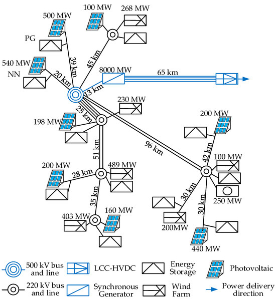
Figure 1.
Configuration of large-scale HWSS base.
As shown in Figure 2, each RPG station is modeled as an aggregated grid-connected converter, with generator-side dynamics neglected due to their low impact on grid-side behavior [20]. Its control system comprises DC-link voltage control (DVC), PS/NS current control (PSCC/NSCC), and a DDSRF-PLL [17,21].
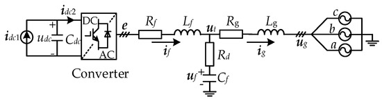
Figure 2.
Configuration of RPG station.
The ESS is implemented using a two-stage converter. The front-stage DC/DC converter boosts the battery’s low voltage to a high DC bus voltage, while the rear-stage converter ensures stable power delivery to the grid. The rear-stage converter adopts a control scheme comprising active power control (APC), reactive power control (RPC), PSCC/NSCC, and DDSRF-PLL. The boost converter implements a control strategy consisting of DVC and direct current control (DCC) [22].
The rectifier station consists of a 12-pulse LCC, commutating transformers, AC filters, and a DC smoothing reactor [23]. As shown in Figure 3a, the 12-pulse LCC is formed by two 6-pulse LCCs, with a 30° phase shift between the secondary windings of the commutating transformers. Its control scheme, illustrated in Figure 3b, includes DCC and a PLL. The hydropower plant comprises four identical 2000 MW synchronous generators (SGs), aggregated into a single equivalent 8000 MW SG. Its control scheme includes excitation control and speed control [24,25].
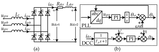
Figure 3.
(a) Configuration of 6-pulse LCC; (b) control scheme of rectifier station.
3. Small-Signal Modeling of the Studied System
In this section, the LTP model of the large-scale HWPS base is established by linearizing around periodic trajectories. The small-signal modeling details of the ESS and SG can be found in [24,25,26] and are therefore omitted. The following focuses on the small-signal modeling of the RPG station and the rectifier station.
3.1. Small-Signal Modeling of the RPG Station
The physical circuit of the RPG station is shown in Figure 2. Based on Kirchhoff’s Voltage Law (KVL) and Kirchhoff’s Current Law (KCL), the corresponding small-signal equations are derived as follows:
where the prefix “Δ” represents the small-signal perturbation of variables, j = a, b, c, and mj is the converter modulation ratio. The control scheme of the RPG station has been detailed in [17,26] and is therefore omitted.
3.2. Small-Signal Modeling of the Rectifier Station
The switching function method is commonly used to describe the switching dynamics of the LCC [23]. Here, as illustrated in Figure 3a, a 6-pulse LCC is taken as an example for derivation, which can be readily extended to the 12-pulse LCC. Considering the voltage/current relationships on both the AC and DC sides and including the commutation process, the DC voltage udcr1 and AC current igrj can be expressed as follows:
where Sij denotes the current switching function, and Suj denotes the voltage switching function. Taking phase A as an example and neglecting higher-order components, these can be expressed as
where ω0 = 2πf0 is the rated angular frequency, and μ denotes the commutation overlap angle, which can be expressed as
where Vs is the AC voltage amplitude, and αact is the actual firing angle, determined by the DCC output firing angle and the dynamics of the PLL:
where φ is the AC voltage phase. By reflecting the commutation inductance to the DC side, the equivalent DC-side inductance can be expressed as
Accordingly, the small-signal equation of DC current can be derived as
3.3. LTP Modeling of the Large-Scale HWPS Base
After establishing the LTP models of the RPG station, ESS, hydropower plant, and rectifier station, the component connection method (CCM) [9] is adopted to interconnect them with the network equations, resulting in the final small-signal model of the large-scale HWPS base. Specifically, the LTP small-signal models of the individual subsystems can be uniformly expressed as follows:
where xdevice, udevice, and ydevice denote the vectors of state, input, and output variables of each subsystem, respectively. The subscript device represents each node component, such as RPGi for the i-th RPG station, ESSi for the i-th ESS, SG for the hydropower plant, and LCC for the rectifier station. The system matrices 𝐴device (𝑡), Bdevice (𝑡), Cdevice (𝑡), and Ddevice (𝑡) are all periodic with a fundamental period T. The output currents of each node component and the voltages at the connection points serve as interface variables, which are linked to the network equations. The network equations can be expressed in a similar form:
The interconnections between all components are illustrated in Figure 4. By eliminating the algebraic variables, the resulting LTP model of the large-scale HWPS base consists of 754 state variables and can be expressed in the following compact form:
where the state matrix A(t) is periodic with the fundamental period T. The detailed expressions of A(t) are omitted here due to space limitations.
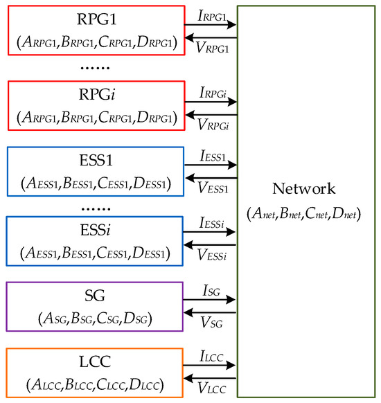
Figure 4.
Implementation of large-scale HWPS base modeling with CCM.
3.4. Validation of the Small-Signal Model
In this section, the accuracy of the constructed LTP model of the large-scale HWPS base is demonstrated by comparing its results with those of the nonlinear time-domain model. The main system parameters are provided in Appendix A. The control parameters are referenced from [20,23,26]; they were originally designed for single-machine infinite bus (SMIB) scenarios and slightly adjusted to ensure system stability. The network and equipment capacity parameters are derived from a real project located in southwest China.
A 0.05 pu perturbation is applied to the DC voltage of the NN RPG station, as shown in Figure 4, and the corresponding dynamic responses of the DC voltage udc and the d-axis component of PSCC xid+ are shown in Figure 5. It can be seen that the results of the LTP model (blue dashed line) closely match those of the nonlinear MMC model (red solid line), thereby verifying the accuracy of the constructed small-signal model of the large-scale HWPS base.
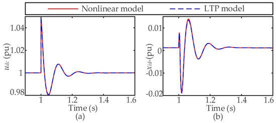
Figure 5.
Time-domain response comparison between original nonlinear model and LTP model: (a) DC voltage udc; (b) d-axis component of PSCC xid+.
4. LTP Stability Analysis of the Large-Scale HWPS Base
Since the NN RPG station has the largest capacity among all eleven RPG stations and is located closest to the hydropower plant and rectifier station, this section employs eigenvalue analysis to investigate the impact of the NN RPG station and ESS control parameters on the stability of the large-scale HWPS base. The system parameters used in this study are provided in Appendix A.
4.1. Eigenvalue Analysis Based on Floquet Theory
The compact form of the LTP model of the large-scale HWPS base under study is shown in (13). According to Floquet theory, there is a time-periodic transformation matrix R(t) that makes (13) time-invariant:
where Q is the time-invariant matrix whose eigenvalues equivalently characterize the stability of the LTP system.
Unfortunately, the matrix R(t) cannot generally be obtained in closed form. As noted in [27], it can be computed indirectly via the state transition matrix (STM), which characterizes the evolution of the system state from time t0 to time t:
By setting t0 = 0 and t = T, Ф(T, 0) represents the state transition over one period. The time-invariant matrix Q can then be expressed as
The system is stable only if all eigenvalues of matrix Q have negative real parts; otherwise, the system is unstable. In addition, it is worth noting that the frequencies derived from the imaginary parts of these eigenvalues are referred to as modal frequencies, which may differ from the actual oscillation frequencies by nf0, where n is an integer.
Although STM can be computed via numerical integration [17], this study employs the discrete exponential expansion (DEE) method [28] to accelerate computation. Reference [28] compared several methods for calculating the STM and indicated that DEE achieves the fastest computation, highlighting its advantage, which is especially important for large-scale systems. Specifically, the time interval [0, T] is divided into N subintervals with step size Δt = T/N. If Δt is sufficiently small, A(t) can be considered constant within each subinterval. Then, the STM over one period can be expressed as
Therefore, the overall procedure for the stability analysis of the large-scale HWPS base is summarized in Figure 6. First, the LTP models of individual components are established. Second, based on the CCM, all nodes are interconnected with the network, and by eliminating the algebraic variables, a compact LTP model of the large-scale HWPS base is obtained. Third, the system’s STM is efficiently computed using (17). Finally, the eigenvalues of matrix Q are calculated according to (16) to determine system stability.
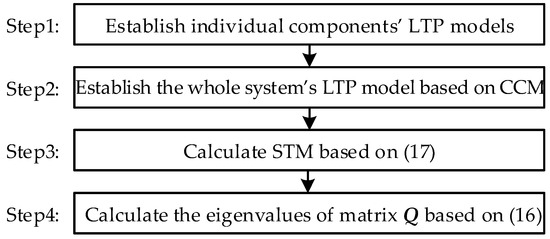
Figure 6.
Overall procedure for stability analysis of large-scale HWPS base.
4.2. Impact of NN RPG Station
(1) PLL control: This part analyzes the impact of the PLL bandwidth (BW) of the NN RPG station on system stability. As BW varies from 0 to 100 Hz, the eigenvalue locus of the system is as shown in Figure 7. It can be observed that as the PLL BW increases, two pairs of modes (λ1,2 and λ3,4) gradually move toward the right half-plane, indicating enhanced stability. This also suggests that an excessively low PLL BW may be detrimental to system stability. Moreover, when the PLL BW is small, the frequencies of these two pairs of modes decrease, which is consistent with the analysis in [6], indicating that a low PLL BW may cause low-frequency oscillations. As the BW continues to increase, the modes λ5,6 shift further toward the right half-plane, implying a reduction in stability. This agrees with [6], which showed that a high PLL BW may induce higher-frequency oscillations, possibly due to resonance introduced by the LCL filter. These two oscillation risks are caused by different modes, exhibiting distinct characteristics. This highlights the importance of properly designing the PLL bandwidth to ensure reliable system operation.
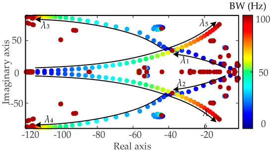
Figure 7.
Eigenvalue locus of large-scale HWPS base with change in PLL BW of NN RPG station.
(2) DVC control: This part investigates the impact of the DVC BW of the NN RPG station on system stability. As BW varies from 1 to 100 Hz, the eigenvalue locus of the system is as shown in Figure 8. It can be observed that as the DVC BW increases, one pair of dominant modes changes significantly, and the change is not linear, indicating strong nonlinear effects. The system exhibits oscillatory instability risks when the DVC BW is either too small or too large. Specifically, when the DVC BW is below 2 Hz or above 74 Hz, the modal eigenvalues are 1.060 ± 1.04 × 2πj and 1.062 ± 6.486 × 2πj, respectively, indicating system instability.
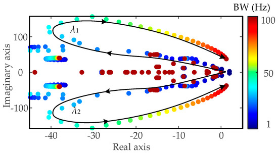
Figure 8.
Eigenvalue locus of large-scale HWPS base with change in DVC BW of NN RPG station.
To validate the above analytical results, time-domain simulations were conducted. At 1 s, the DVC BW was changed from 15 to 74 Hz, and the results are shown in Figure 9. The DC voltage waveform in Figure 9a exhibits a diverging oscillation, while the FFT analysis in Figure 9b reveals an oscillation frequency of 43.5 Hz, shifted by f0 from the modal frequency. The terminal Phase-A current and voltage waveforms, shown in Figure 9c,e, also display diverging oscillations. Their FFT results indicate oscillation components at |43.5 ± 50| Hz, with 93.5 Hz being the dominant frequency. Similarly, when the DVC BW was changed from 15 to 2 Hz at 1 s, the simulation results are as shown in Figure 10. The DC voltage waveform in Figure 10a shows a diverging oscillation, and the FFT analysis in Figure 10b identifies an oscillation frequency of 1 Hz, consistent with the modal frequency. The terminal Phase-A current and voltage waveforms in Figure 10c,e also exhibit diverging oscillations, with the FFT results showing oscillation components at |1 ± 50| Hz.
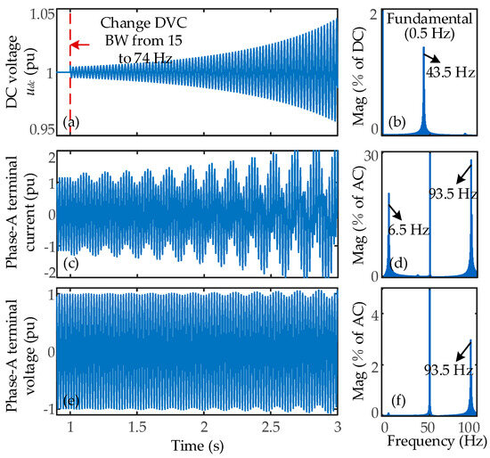
Figure 9.
Changing the DVC BW of the NN RPG station from 15 to 74 Hz: (a) time-domain waveform of DC voltage udc and (b) its FFT analysis results; (c) time-domain waveform of Phase-A terminal current and (d) its FFT analysis results; (e) time-domain waveform of Phase-A terminal voltage and (f) its FFT analysis results.
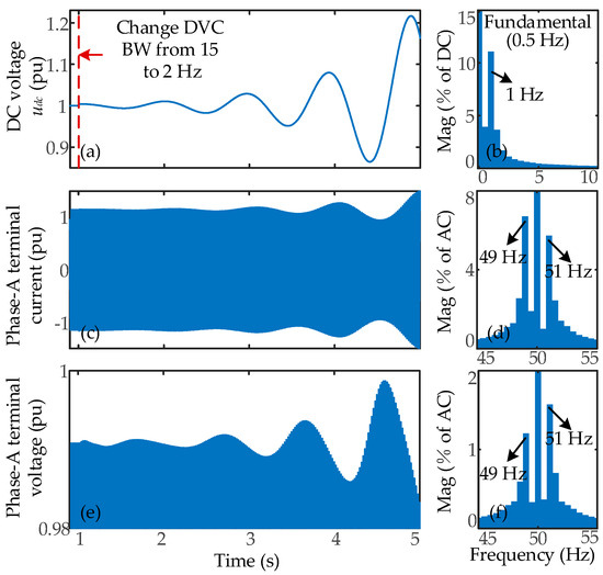
Figure 10.
Changing the DVC BW of the NN RPG station from 15 to 2 Hz: (a) time-domain waveform of DC voltage udc and (b) its FFT analysis results; (c) time-domain waveform of Phase-A terminal current and (d) its FFT analysis results; (e) time-domain waveform of Phase-A terminal voltage and (f) its FFT analysis results.
These time-domain simulation results validate the accuracy of the stability analysis. Moreover, it can be observed that a low DVC BW induces low-frequency oscillations, whereas a high DVC BW leads to sub-synchronous oscillations. This behavior is similar to that observed for the PLL BW; however, the DVC-induced oscillations originate from the same mode under different parameter conditions, while the PLL-induced oscillations arise from different modes.
4.3. Impact of NN ESS
(1) PSCC control: To analyze the impact of the PSCC of the NN ESS on system stability, its BW is varied from 0 to 800 Hz, and the corresponding eigenvalue locus is shown in Figure 11. As the PSCC BW increases, two pairs of dominant modes gradually move toward the imaginary axis, reducing system damping. When the BW exceeds 505 Hz, one pair crosses the imaginary axis, indicating instability. The unstable eigenvalues are 5.113 ± 17.903 × 2πj.
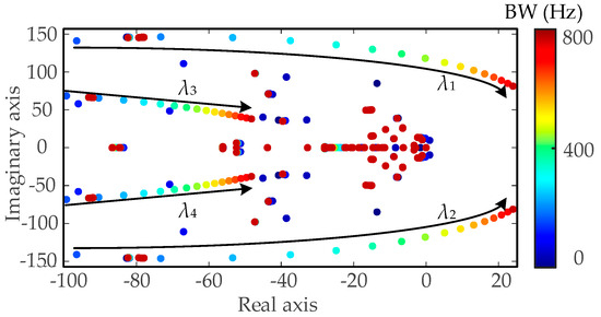
Figure 11.
Eigenvalue locus of large-scale HWPS base with change in PSCC BW of NN ESS.
To validate the accuracy of the stability analysis, time-domain simulations were conducted. At 1 s, the PSCC BW of the NN ESS was changed from 200 to 505 Hz. As shown in Figure 12a, the terminal voltage d-axis component exhibited a diverging oscillation. The FFT analysis in Figure 12b indicates an oscillation frequency of 82 Hz, shifted by 2f0 from the modal frequency. The Phase-A terminal voltage and current waveforms, shown in Figure 12c,e, also display diverging oscillations. Their FFT analysis results, presented in Figure 12d,f, reveal oscillation frequencies at |82 ± 50| Hz, with 32 Hz being the dominant component. These time-domain simulation results validate the accuracy of the stability analysis.
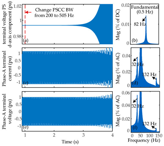
Figure 12.
Changing PSCC BW of NN ESS from 200 to 505 Hz: (a) time-domain waveform of terminal voltage d-axis component and (b) its FFT analysis results; (c) time-domain waveform of Phase-A terminal current and (d) its FFT analysis results; (e) time-domain waveform of Phase-A terminal voltage and (f) its FFT analysis results.
(2) NSCC Control: To analyze the impact of the NSCC on system stability, its BW was varied from 0 Hz to 800 Hz, and the corresponding eigenvalue analysis is shown in Figure 13. As the NSCC BW increases, two pairs of dominant modes shift toward the right half of the complex plane, indicating reduced stability. When the NSCC BW exceeds 590 Hz, one pair of modes crosses the imaginary axis, signifying system instability. The unstable eigenvalues are identified as 5.207 ± 22.252 × 2πj.
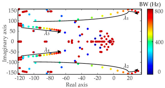
Figure 13.
Eigenvalue locus of large-scale HWPS base with change in NSCC BW of NN ESS.
To validate the accuracy of the stability analysis, time-domain simulations were performed. At 1 s, the NSCC BW was changed from 200 Hz to 590 Hz. As shown in Figure 14a, the terminal voltage d-axis component exhibited a diverging oscillation. The FFT analysis in Figure 14b indicates an oscillation frequency of 27.5 Hz, shifted by f0 from the modal frequency. The Phase-A terminal voltage and current waveforms, shown in Figure 14c,e, also display diverging oscillations. Their FFT analysis results, presented in Figure 14d,f, reveal oscillation frequencies at |27.5 ± 50| Hz, with 22.5 Hz being the dominant component. These time-domain simulation results validate the accuracy of the stability analysis.
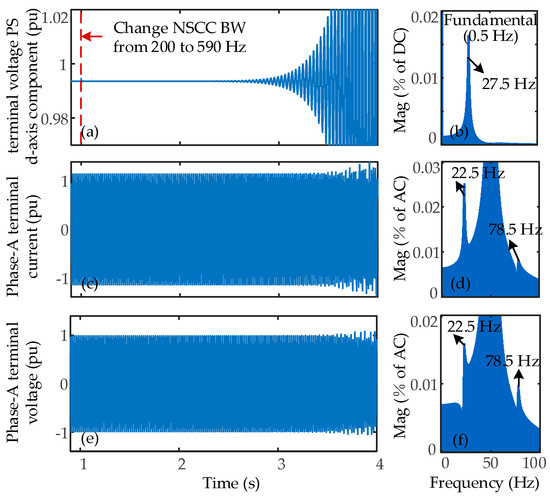
Figure 14.
Changing the NSCC BW of the NN ESS from 200 to 590 Hz: (a) time-domain waveform of terminal voltage d-axis component and (b) its FFT analysis results; (c) time-domain waveform of Phase-A terminal current and (d) its FFT analysis results; (e) time-domain waveform of Phase-A terminal voltage and (f) its FFT analysis results.
4.4. Discussion
In this study, an LTP model of a large-scale HWPS base with NS control is established based on the CCM method. The DEE method is employed to compute the STM, and an eigenvalue analysis approach is adopted to investigate the impacts of RPG and ESS control on system stability. The analysis demonstrates that under the considered operating scenario, these controller parameters can trigger oscillations across a wide frequency range. In particular, low PLL and DVC BWs are associated with low-frequency oscillations, while excessively high BWs tend to induce sub-synchronous oscillations. These findings are validated through time-domain simulations of the nonlinear system model, further emphasizing the importance of properly designing controller parameters to ensure system stability.
In this scenario, the Park transformation fails to decouple the coupling between the positive- and negative-sequence components, rendering conventional dq-domain modeling inapplicable. The DP method encounters difficulties in handling nested trigonometric functions, such as those arising from the PLL [17]. The HSS method requires constructing a doubly infinite Toeplitz matrix, which must be truncated for computation, thereby introducing a trade-off between accuracy and efficiency. Therefore, the LTP-based analysis method offers distinct advantages for wide frequency range stability analysis of large-scale systems [27].
It should be noted that this study focuses solely on small-signal stability, excluding large disturbances and parameter uncertainties, and other possible scenarios. As a physics model-based analytical method, it provides quantitative and physically interpretable stability assessments, which can intuitively guide engineers in stability evaluation and parameter tuning. However, the results are valid only for the specific scenario analyzed; further research is required to extend the applicability to different HWPS topologies or control architectures. Moreover, with the rapid development of data-driven techniques [29,30], hybrid approaches combining physics-based and data-driven models show great potential. Specifically, verified physical models can be used to generate synthetic data for training machine learning models, which can then enable real-time stability prediction based on both the trained models and measured data. This will be further investigated in future work.
5. Conclusions
This study develops an LTP model of a large-scale HWPS base and applies Floquet theory to investigate the impact of control parameters of the NN RPG station and ESS on system stability. The main conclusions are as follows:
- (1)
- The NS control introduces a rotating coordinate transformation that cannot be eliminated through the Park transformation. Therefore, directly linearizing the system around its periodic trajectories to derive an LTP model, combined with Floquet-based stability analysis, provides a feasible approach for assessing the stability of the large-scale HWPS base.
- (2)
- The effects of PLL and DVC BW in the NN RPG station, as well as PSCC/NSCC BW in the NN ESS, on system stability are analyzed. The eigenvalue locus results offer guidance for parameter optimization.
- (3)
- The analysis reveals that under the studied scenario, low PLL and DVC BWs (e.g., 2 Hz) may give rise to low-frequency oscillations, whereas high PLL and DVC BWs (e.g., 74 Hz) may induce sub-synchronous oscillations. Excessively high PSCC and NSCC BWs can also lead to system instability. These findings underscore the importance of carefully designing these control parameters to ensure stable system operation.
Author Contributions
Conceptualization, R.L. and Z.W.; methodology, Z.W. and Y.L.; formal analysis, Z.W., Z.J. and H.X. (Hongqiang Xiao); investigation, Z.W. and H.X. (Hong Xiao); resources, H.X. (Hong Xiao), B.W., D.H. and R.L.; data curation, J.S., H.X. (Hongqiang Xiao) and G.Z.; writing—original draft preparation, Z.W., J.S. and D.H.; writing—review and editing, Z.W., B.W. and Z.J.; supervision, Z.W., G.Z. and R.L.; project administration, Y.L.; funding acquisition, Y.L. All authors have read and agreed to the published version of the manuscript.
Funding
This research was funded by China Yangtze Power Co., Ltd., Contract No. Z532402002.
Data Availability Statement
The original contributions presented in this study are included in the article; further inquiries can be directed to the corresponding author.
Conflicts of Interest
Authors Ruikuo Liu, Jingshu Shi, and Depeng Hu were employed by the company Science and Technology Research Institute China Three Gorges Corporation. Authors Hong Xiao, Bin Wang, and Ziqi Jia were employed by the company Ningnan Baihetan Power Plant of Three Gorges Jinsha River Yunchuan Hydropower Development Co., Ltd. The remaining authors declare that the research was conducted in the absence of any commercial or financial relationships that could be construed as a potential conflict of interest. The authors declare that this study received funding from China Yangtze Power Co., Ltd. The funder was not involved in the study design, collection, analysis, interpretation of data, the writing of this article, or the decision to submit it for publication.
Appendix A

Table A1.
Parameters of studied system.
Table A1.
Parameters of studied system.
| Symbol | Values | Symbol | Values | Segment |
|---|---|---|---|---|
| Ubase | 690 V | idc1 | 0.41 pu | RPG station |
| Udc | 1100 V | PLL (ζpll, BW) | 0.7, 7 | |
| Lf, Rf | 0.1 pu, 0.003 pu | PSCC (ζi+, BW) | 1.6, 200 | |
| Cf, Rd | 0.1 pu, 0.75 pu | NSCC (ζi-, BW) | 1.6, 200 | |
| αf, ωc | 1.5 ω0, 1.414 ω0 | DVC (ζdvc, BW) | 0.3, 15 | |
| Sbase of each transformer | 4755 MW | udcr2 | 1600 kV | Rectifier station |
| Tr | 525 kV/756.45 kV | αf | 3.2ω0 | |
| Lr | 0.18 pu | PLL (kppllr, kipllr) | 10, 50 | |
| Ld, Rd | 2.5 Ω, 0.5968 H | DCC (kpdcc, kidcc) | 0.4, 6 | |
| 0.92 pu | ||||
| Ubase | 690 V | PLL (ζpll, BW) | 0.7, 7 | ESS |
| Udc | 1100 V | PSCC (ζi+, BW) | 1.6, 200 | |
| Lf, Rf | 0.1 pu, 0.003 pu | NSCC (ζi-, BW) | 1.6, 200 | |
| E0 | 600 V | APC (kpP, kiP) | 0.5, 40 | |
| Ldc, Cdc | 0.1 pu, 0.09 pu | RPC (kpQ, kiQ) | 0.5, 40 | |
| αf, ωc | 1.5 ω0, 1.414 ω0 | DVC (kpv, kiv) | 0.5, 20 | |
| 1 pu | DCC (kpc, kic) | 1, 80 | ||
| 1.018 pu | Tsm | 0.3 | SG | |
| ω* | 1 pu | Ka | 100 | |
| P* | 0.7 pu | Ta | 0.04 | |
| Kg | 40 |
The parameters of the rectifier’s AC filter refer to [31].
References
- Zhan, Y.; Xie, X.; Liu, H.; Liu, H.; Li, Y. Frequency-domain modal analysis of the oscillatory stability of power systems with high-penetration renewables. IEEE Trans. Sustain. Energy 2019, 10, 1534–1543. [Google Scholar] [CrossRef]
- Wang, X.; Blaabjerg, F. Harmonic stability in power electronic-based power systems: Concept, modeling, and analysis. IEEE Trans. Smart Grid. 2019, 10, 2858–2870. [Google Scholar] [CrossRef]
- Bazargan, D.; Filizadeh, S.; Gole, A.M. Stability analysis of converter-connected battery energy storage systems in the grid. IEEE Trans. Sustain. Energy 2014, 5, 1204–1212. [Google Scholar] [CrossRef]
- Bhavani, R.; Dhanalakshmi, U.; Kamal, C. A multi-level single-phase grid connected converter for renewable distributed system. Int. J. Electr. Electron. Eng. Telecommun. 2015, 1, 311–318. [Google Scholar]
- Qiao, L.; Xue, Y.; Kong, L.; Wang, F. Nupur Small-signal stability analysis for large-scale power electronics-based power systems. IEEE Open Access J. Power Energy 2024, 11, 280–292. [Google Scholar] [CrossRef]
- Musengimana, A.; Li, H.; Zheng, X.; Yu, Y. Small-signal model and stability control for grid-connected pv inverter to a weak grid. Energies 2021, 14, 3907. [Google Scholar] [CrossRef]
- Givaki, K.; Chen, D.; Xu, L. Current error based compensations for vsc current control in weak grids for wind farm applications. IEEE Trans. Sustain. Energy 2019, 10, 26–35. [Google Scholar] [CrossRef]
- Farrokhabadi, M.; König, S.; Cañizares, C.A.; Bhattacharya, K.; Leibfried, T. Battery energy storage system models for microgrid stability analysis and dynamic simulation. Power Syst. IEEE Trans. (T-PWRS) 2018, 33, 2301–2312. [Google Scholar] [CrossRef]
- Wang, Y.; Wang, X.; Chen, T.; Blaabjerg, F. Small-signal stability analysis of inverter-fed power systems using component connection method. IEEE Trans. Smart Grid. 2018, 9, 5301–5310. [Google Scholar] [CrossRef]
- Luo, J.; Zou, Y.; Bu, S. Converter-driven stability analysis of power systems integrated with hybrid renewable energy sources. Energies 2021, 14, 4290. [Google Scholar] [CrossRef]
- Jamehbozorg, A.; Radman, G. Small signal analysis of power systems with wind and energy storage units. IEEE Trans. Power Syst. 2015, 30, 298–305. [Google Scholar] [CrossRef]
- Rueda, J.; Erlich, I. Impact of large scale integration of wind power on power system small-signal stability. In Proceedings of the 2011 International Conference on Electric Utility Deregulation and Restructuring and Power Technologies, Weihai, China, 6–9 July 2011; pp. 673–681. [Google Scholar] [CrossRef]
- He, P.; Fang, Q.; Jin, H.; Ji, Y.; Gong, Z.; Dong, J. Coordinated design of PSS and STATCOM-POD based on the GA-PSO algorithm to improve the stability of wind-PV-thermal-bundled power system. Int. J. Electr. Power Energy Syst. 2023, 141, 108208. [Google Scholar] [CrossRef]
- Shang, L.; Dong, X.; Liu, C.; Gong, Z. Fast grid frequency and voltage control of battery energy storage system based on the amplitude-phase-locked-loop. IEEE Trans. Smart Grid. 2022, 13, 941–953. [Google Scholar] [CrossRef]
- Montero-Robina, P.; Rouzbehi, K.; Gordillo, F.; Pou, J. Grid-following voltage source converters: Basic schemes and current control techniques to operate with unbalanced voltage conditions. IEEE Open J. Ind. Electron. Soc. 2021, 2, 528–544. [Google Scholar] [CrossRef]
- Achlerkar, P.D.; Panigrahi, B.K. New perspectives on stability of decoupled double synchronous reference frame PLL. IEEE Trans. Power Electron. 2022, 37, 285–302. [Google Scholar] [CrossRef]
- Zhu, J.; Hu, J.; Wang, S.; Wan, M. Small-signal modeling and analysis of MMC under unbalanced grid conditions based on linear time-periodic (LTP) method. IEEE Trans. Power Deliv. 2021, 36, 205–214. [Google Scholar] [CrossRef]
- Yang, H.; Dieckerhoff, S. Truncation order selection method for LTP-theory-based stability analysis of converter dominated power systems. IEEE Trans. Power Electron. 2021, 36, 12168–12172. [Google Scholar] [CrossRef]
- De Rua, P.; Sakinci, Ö.C.; Beerten, J. Comparative study of dynamic phasor and harmonic state-space modeling for small-signal stability analysis. Electr. Power Syst. Res. 2020, 189, 106626. [Google Scholar] [CrossRef]
- Lin, L.; Zeng, Q.; Zhu, J.; Shi, X.; Hu, J. High-frequency oscillation mechanism analysis and suppression strategy of grid-forming control MMC-HVDC. IEEE Trans. Power Deliv. 2023, 38, 1588–1600. [Google Scholar] [CrossRef]
- Liu, S.; Liu, P.X.; Wang, X. Stability analysis of grid-interfacing inverter control in distribution systems with multiple photovoltaic-based distributed generators. IEEE Trans. Ind. Electron. 2016, 63, 7339–7348. [Google Scholar] [CrossRef]
- Sanchis, P.; Ursaea, A.; Gubia, E.; Marroyo, L. Boost DC-AC inverter: A new control strategy. IEEE Trans. Power Electron. 2005, 20, 343–353. [Google Scholar] [CrossRef]
- Du, B.; Zhu, J.; Hu, J.; Guo, Z.; Ma, S.; Guo, J. Small-signal modeling of LCC-HVDC considering switching dynamics based on the linear time-periodic (LTP) method. IEEE Trans. Power Deliv. 2024, 39, 2715–2728. [Google Scholar] [CrossRef]
- Working Group Prime Mover and Energy Supply. Hydraulic turbine and turbine control models for system dynamic studies. IEEE Trans. Power Syst. 1992, 7, 167–179. [Google Scholar] [CrossRef]
- IEEE SSR Working Group. First benchmark model for computer simulation of subsynchronous resonance. IEEE Trans. Power Appar. Syst. 1977, 96, 1565–1572. [Google Scholar] [CrossRef]
- Xiao, H.; Wu, Z.; Liu, R.; Zhang, Z.; Wang, B.; Wang, D.; Shi, J.; Zhao, G. Small-signal stability of PV/BESS grid-connected system considering dynamic of boost converter and negative sequence control. In Proceedings of the 2025 IEEE International Conference on Power Systems and Smart Grid Technologies, Beijing, China, 15–18 April 2025; pp. 338–343. [Google Scholar] [CrossRef]
- Hu, J.; Guo, Z.; Zhu, J.; Kurths, J.; Hou, Y.; Du, B.; Wu, Z.; Zhao, G.; Liu, Y.; Xin, K.; et al. Electromagnetic dynamic stability analysis of power electronics-dominated systems using eigenstructure-preserved LTP theory. Nat. Commun. 2025, 16, 6852. [Google Scholar] [CrossRef]
- Agundis-Tinajero, G.; Segundo-Ramirez, J.; Pena-Gallardo, R.; Visairo-Cruz, N.; Nunez-Gutierrez, C.; Guerrero, J.M.; Savaghebi, M. Harmonic issues assessment on pwm vsc-based controlled microgrids using newton methods. IEEE Trans. Smart Grid. 2018, 9, 1002–1011. [Google Scholar] [CrossRef]
- Wu, Y.; Wu, H.; Cheng, L.; Zhou, J.; Zhou, Z.; Chen, M.; Wang, X. Impedance Profile Prediction for Grid-Connected VSCs With Data-Driven Feature Extraction. IEEE Trans. Power Electron. 2025, 40, 3043–3061. [Google Scholar] [CrossRef]
- Deng, R.; Jiang, Q.; Zhou, X.; Wang, Y.; Sun, M. Eigenvalue-Oriented Data-Driven Small-Signal Stability Assessment for DC Microgrids. IEEE Trans. Power Syst. 2025, 40, 3563–3575. [Google Scholar] [CrossRef]
- Faruque, M.O.; Zhang, Y.; Dinavahi, V. Detailed modeling of CIGRE HVDC benchmark system using PSCAD/EMTDC and PSB/SIMULINK. IEEE Trans. Power Deliv. 2006, 21, 378–387. [Google Scholar] [CrossRef]
Disclaimer/Publisher’s Note: The statements, opinions and data contained in all publications are solely those of the individual author(s) and contributor(s) and not of MDPI and/or the editor(s). MDPI and/or the editor(s) disclaim responsibility for any injury to people or property resulting from any ideas, methods, instructions or products referred to in the content. |
© 2025 by the authors. Licensee MDPI, Basel, Switzerland. This article is an open access article distributed under the terms and conditions of the Creative Commons Attribution (CC BY) license (https://creativecommons.org/licenses/by/4.0/).