1. Introduction
Compared with permanent magnet synchronous motor (PMSM) control technologies that rely on physical encoder position sensors, the sensorless control technology for PMSMs estimates the rotor position and speed in real time through algorithms. This eliminates the need for expensive hardware such as encoders, which not only significantly reduces the system cost and volume but also improves mechanical reliability. It also avoids problems related to sensor installation alignment and potential faults of sensors in harsh environments such as high temperatures and vibrations, resulting in a more compact motor system structure and stronger robustness [
1,
2].
Due to the inherent harmonic characteristics of PMSMs and the coupling properties of nonlinear components in the system, square-wave voltage signals contain abundant high-order harmonics (especially odd-order harmonics). After these harmonic components enter the position observer through the high-frequency response current of the motor, the nonlinear demodulation characteristics of position extraction algorithms such as Phase-Locked Loops (PLL) or arctangent functions will cause multi-frequency harmonic errors in the rotor position estimation. When this position error is further processed by the speed observer (usually a low-pass filter), although its high-frequency components are attenuated, low-frequency harmonics (especially integer multiples of the fundamental frequency) cannot be completely filtered out due to the bandwidth limitation of the speed loop. Eventually, these low-frequency harmonics are demodulated into low-frequency periodic torque fluctuations, forcing the electromagnetic torque to oscillate accordingly, which manifests as obvious speed chattering on the mechanical shaft [
3,
4].
To address the speed chattering problem caused by high-order harmonics generated by high-frequency injection signals, Reference [
5] combines a first-order Active Disturbance Rejection Controller (ADRC) in the speed loop with high-frequency square-wave injection, while Reference [
6] proposes a high-frequency pulse voltage signal injection method based on enhanced Linear Active Disturbance Rejection Control (LADRC). Both methods establish cascaded extended state observers to ensure relatively timely and accurate estimation of total disturbances, which can effectively solve the speed chattering problem caused by high-frequency injections. Reference [
7] adopts different pole placement strategies in the acceleration phase and steady-state phase; this dynamic pole placement ensures the system response speed while effectively reducing speed chattering. Based on the sensorless control with high-frequency square-wave injection, this paper proposes an improved control strategy: replacing the traditional PI-PLL with an Extended State Observer Phase-Locked Loop (ESO-PLL) to improve the accuracy of rotor position estimation and designing dynamic pole placement for the speed loop. Different pole configurations are used under loaded/unloaded and steady-state/unsteady-state conditions to enhance the robustness of the motor.
On the other hand, in sensorless control systems, position estimation errors are inevitable in environments with large load disturbances. When the error is large, it may lead to incorrect polarity judgment and thus result in speed regulation failure [
8]. References [
9,
10] improve the estimation accuracy by modifying the high-frequency signal injection method. Reference [
9] proposes an improved rotating injection method, which uses the injected negative sequence component as a compensation term to eliminate rotor position errors. However, there are still certain errors in rotor position estimation when the speed fluctuates significantly. Reference [
10] presents an improved pulse injection method: it calculates the possible rotor position by injecting a series of phase-axis voltages, then injects two reciprocal voltage pulses to obtain the rotor polarity and finally injects iterative voltage vectors to quickly obtain the actual position. During the estimation process, no filter is required to extract high-frequency current signals. References [
11,
12,
13] point out that there is a close connection between the pole placement of PMSMs and the load torque, which is mainly reflected in the control system design, dynamic response performance, and disturbance suppression capability.
By introducing a more advanced observer to replace the traditional PI regulator, the uncertainties in the rotor motion equation, such as position, speed, and changes in load torque, are uniformly regarded as total disturbances, which are then observed and compensated. This effectively suppresses the estimation delay and errors caused by dynamic speed changes or sudden load changes, enabling the system to track the actual rotor position signal more quickly and accurately [
14,
15]. Reference [
16] proposes a high-order PLL for detecting the rotor convergence point, which not only reduces the position estimation error but also enables the motor to switch between forward and reverse rotation. Reference [
17] presents an adaptive second-order sliding mode observer based on the Super-Twisting Algorithm (STA-SMO) for estimating the rotor position and speed of PMSMs. A new form of disturbance term is adopted, and an adaptive sliding mode coefficient related to the absolute value of the estimated speed is derived according to the stability conditions of the STA-SMO, ensuring performance over a wide range of positive and negative speeds. Compared with the traditional PI-PLL, it has higher position estimation accuracy.
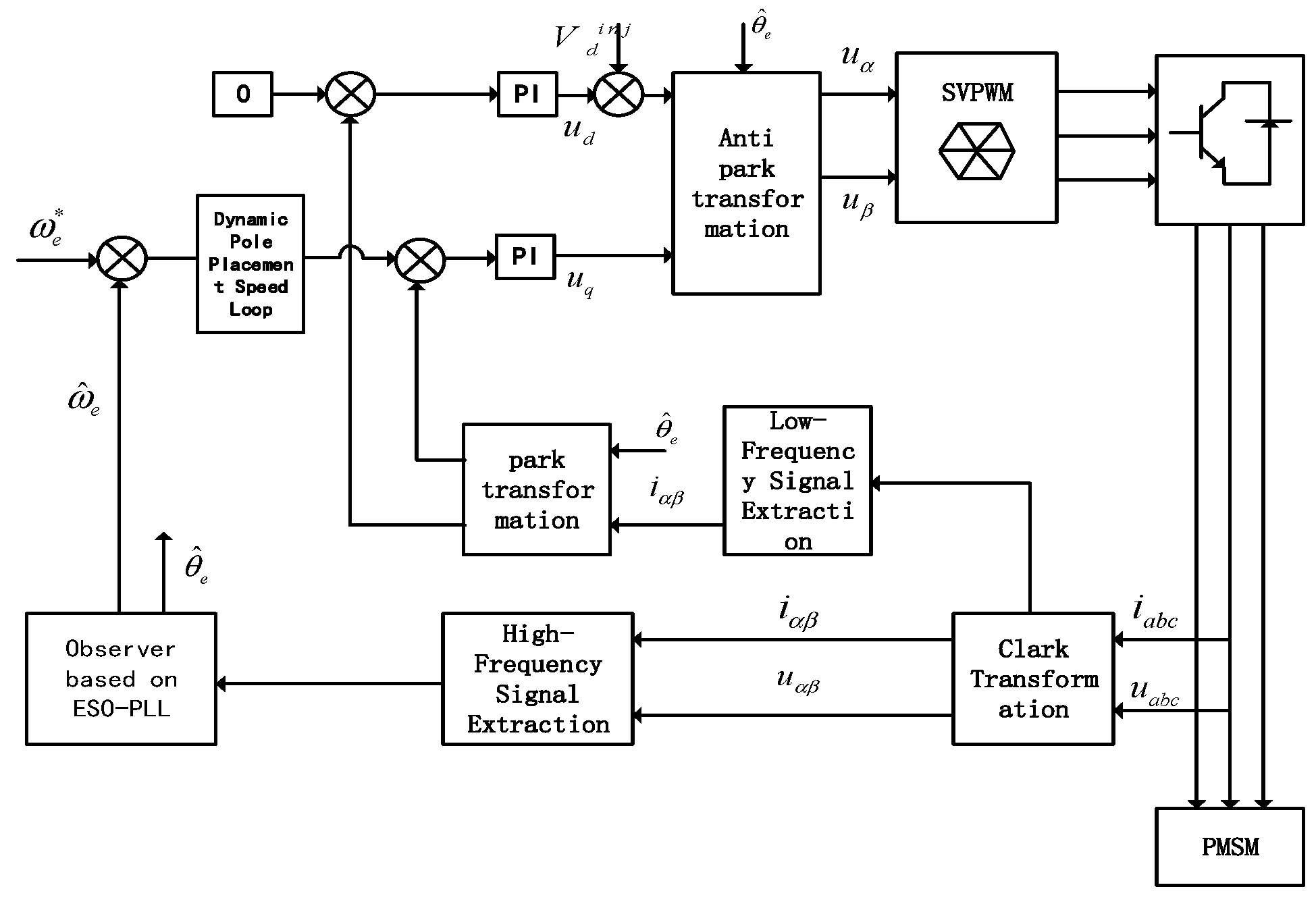
Based on the sensorless control with high-frequency injections, this paper proposes a coordinated control strategy combining ESO-PLL and dynamic pole placement. Firstly, dynamic pole placement is designed for the speed loop to solve the harmonic interference and load disturbance problems of PMSMs in the low-speed range caused by high-frequency square-wave injection. Secondly, an extended state observer is used to uniformly model position errors, speed errors, and total disturbances, realizing high-precision observation and compensation of nonlinear dynamics.
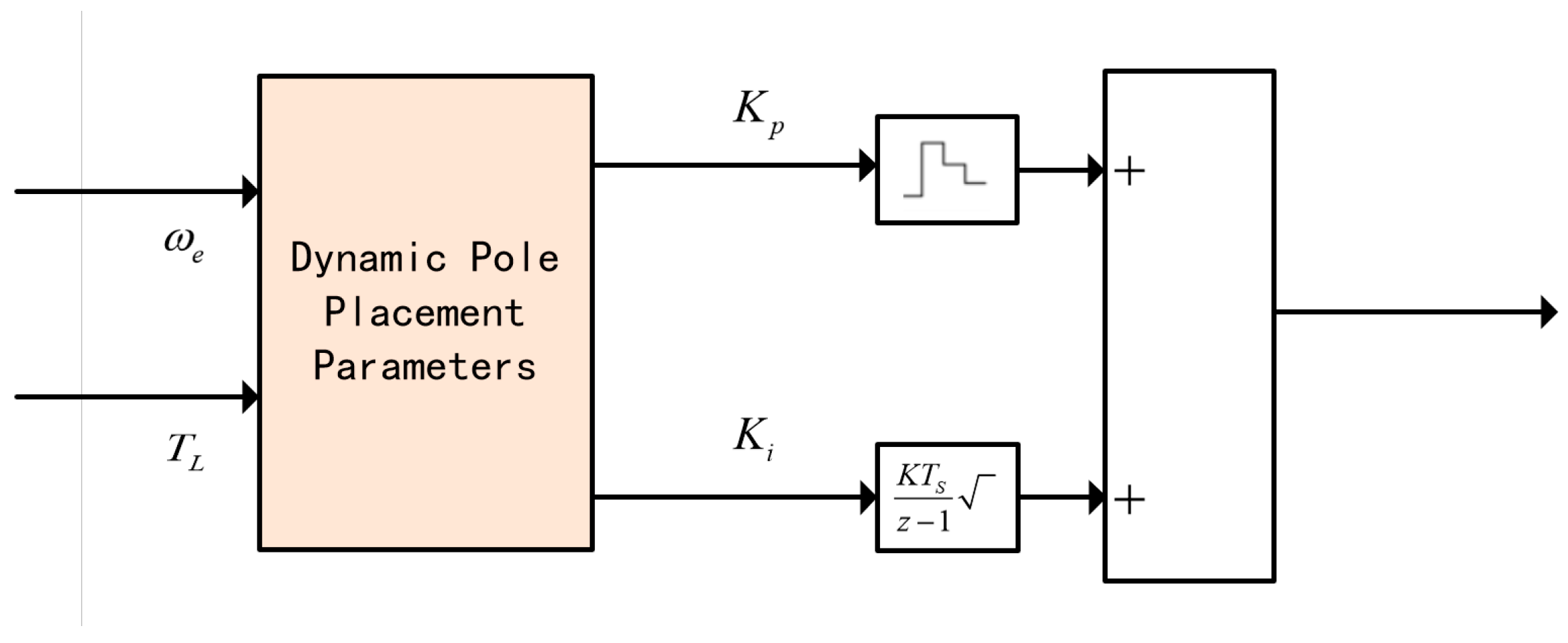
Figure 1 corresponds to the research method of “Dynamic Pole Placement of the Speed Loop”, which is one of the core control links to solve the problems of speed chattering, harmonic interference, and load disturbance caused by high-frequency square wave injection in the low-speed range (200–500 r/min) of permanent magnet synchronous motors (PMSMs). The logical framework of this method is as follows:
This method takes “motor speed error” and load torque as the core inputs and realizes the dynamic optimization of speed loop controller parameters (damping ratio ξ, bandwidth by designing an adaptive pole adjustment mechanism. Specifically, the motor’s operating state is first determined based on the speed error: when the speed error is less than 5 r/s, it is judged as the steady state, and “small poles” are switched to reduce speed fluctuations and position estimation errors, thereby suppressing harmonic interference caused by high-frequency square wave injection; when the speed error is ≥5 r/s, it is judged as the transient state (e.g., start-up, speed switching phases), and “large poles” are adopted to accelerate the system response speed and shorten the transition time. Meanwhile, in response to differences between loaded and unloaded operating conditions, this mechanism synchronously adapts the pole parameters to ensure the system remains stable when the load changes suddenly.
In the signal processing and control output links, this method combines current loop PI regulation (Equation (6)) and feedforward decoupling (Equation (5)) to convert the control quantity output by dynamic pole placement into dq-axis voltage commands. These commands act on the motor in coordination with the high-frequency square wave injection signal, ultimately achieving a balance between “dynamic response speed” and “steady-state control accuracy”. This lays a foundation for the subsequent improvement of rotor position estimation accuracy and suppression of total disturbances via ESO-PLL (Extended State Observer-Phase-Locked Loop) in the speed loop control. Among them,
Table 1 provides the parameters of the permanent magnet synchronous motor.
The literature [
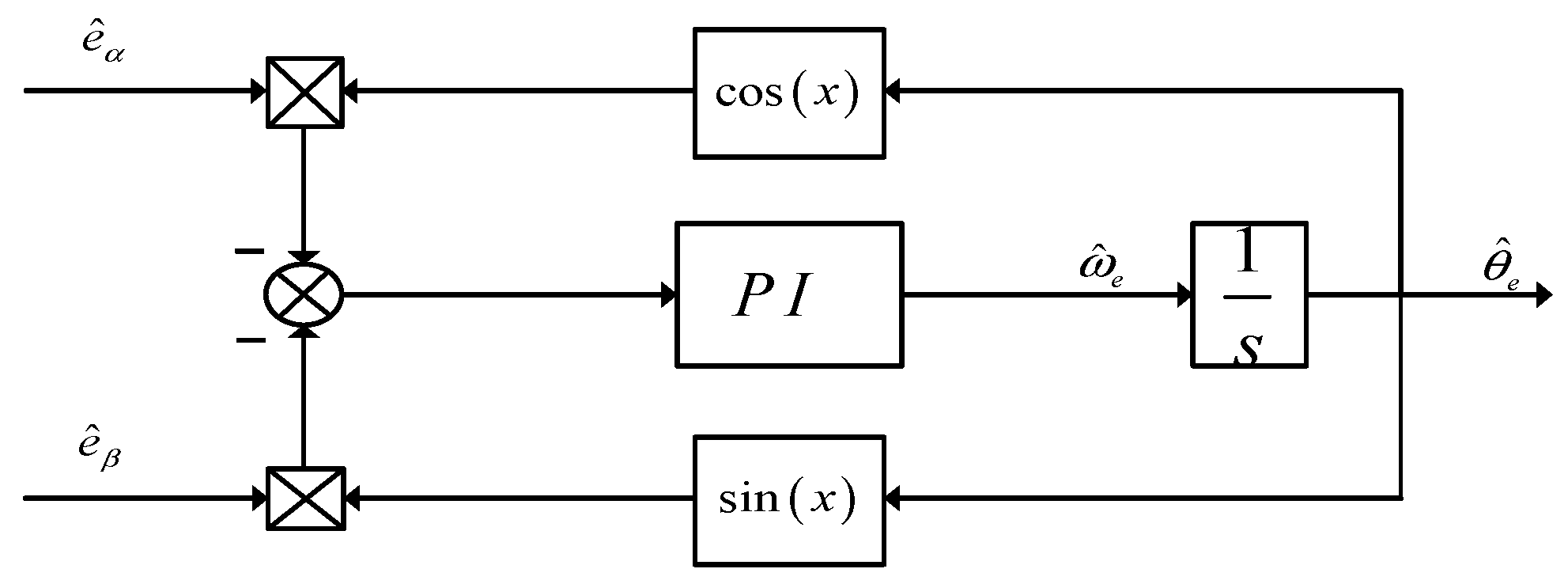
18] proposes a sensorless control method for Permanent Magnet Synchronous Motors (PMSM) that combines a Fifth-Order Generalized Integral Flux Observer (FOGIFO) and a Phase-Locked Loop based on an Extended State Observer (ESO_PLL). It optimizes the pole distribution of FOGIFO to enhance harmonic suppression performance and analyzes the conventional Phase-Locked Loop based on the error transfer function. This ESO_PLL is used for observing rotor position and speed, significantly improving dynamic tracking performance. The research in this article demonstrates the feasibility of combining the ESO Phase-Locked Loop with dynamic pole configuration, providing theoretical support for the research in this paper.
2. Dynamic Pole Placement of the Speed Loop
The traditional speed loop often adopts a PI control strategy with fixed pole design. However, in actual operation, the motor faces complex and variable working conditions: a fast response is required during the start-up phase to shorten the transition time; harmonic interference caused by high-frequency square wave injection needs to be suppressed during the steady-state phase to reduce speed fluctuations; and the difference in load torque between loaded and no-load states can also lead to changes in the dynamic characteristics of the system. To address these issues, this paper proposes a dynamic pole placement strategy for the speed loop. By establishing a pole adjustment mechanism that adaptively matches the motor’s operating states (loaded/no-load, steady-state/transient), real-time optimization of the controller’s damping ratio and bandwidth parameters is achieved, laying a control foundation for solving the problems of harmonic interference and load disturbance in the low-speed range. In response to complex torque disturbances, this paper presents a speed loop with nonlinear pole placement based on high-frequency injection sensorless control, aiming to enhance the robustness of the motor during low-speed operation under nonlinear torque disturbances.
In the dq rotating coordinate system, the voltage equations of the Permanent Magnet Synchronous Motor (PMSM) are as follows:
where
denotes the permanent magnet flux linkage. The electromagnetic torque is expressed as:
The expression for the load torque is:
where
represents the speed integral and
represents the speed error integral. To eliminate the coupling terms, feedforward decoupling is employed, and PI control is introduced:
By substituting Equation (1), since the bandwidth of the current loop is much higher than that of the speed loop, the stator resistances (, ) can be neglected at high frequencies (where the inductive voltage drop dominates). Meanwhile, the feedforward decoupling has completely canceled out the cross-coupling terms (, ), so the decoupled dq-axis voltage commands can be approximately equal to the output voltage of the PI regulator.
Substitute the current dynamic equations into the PI expressions:
After rearrangement, the closed-loop transfer functions are obtained:
The current loop, as a second-order system, includes the damping ratio
and the natural frequency
:
By comparing with the denominator of the closed-loop transfer function:
The PI parameters are solved as follows:
Figure 2 shows the system block diagram of the improved speed loop, which takes the speed error and load torque (
) as input items to realize the dynamic pole placement of the speed loop, where K is the proportional gain of the speed loop controller, and Ts is the discrete sampling period.
A fixed large pole may result in excessive position estimation errors during low-speed start-up, potentially causing motor runaway. In contrast, a small pole leads to small steady-state errors but slow response.
A speed error of less than 5 r/s is defined as the steady state, and otherwise, it is the transient state. The motor’s operating states are categorized into loaded steady-state, loaded transient, no-load steady-state, and no-load transient. Different pole placements are adopted for each state to enhance the robustness of the system. A larger pole is used during the start-up phase to accelerate the response. During the transition phase, the pole smoothly decays to a smaller value . After the dynamic adjustment of the pole, the system achieves both fast response and high-precision steady-state estimation.
4. Simulation and Experimental Results
To verify the effectiveness of the sensorless control method for permanent magnet synchronous motors (PMSM) based on the phase-locked loop (PLL) with an improved extended state observer (ESO) in the low-speed range, simulation experiments were conducted using MATLAB/Simulink. Under no-load conditions, with given speeds of 200 rpm and 300 rpm, performance comparisons were carried out between the improved ESO-PLL speed control system and the traditional PI-PLL speed control system. The following are the results of the simulation experiments.
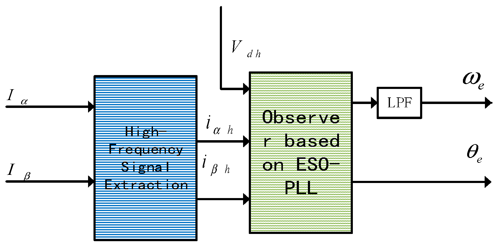
Figure 7 intuitively presents the waveform characteristics of the high-frequency square wave voltage signal injected into the dq-axis of the PMSM. In this study, the frequency of this injected high-frequency square wave signal is set to 2 kHz, and this parameter is a core value determined comprehensively based on the system’s control requirements and motor characteristics.
In
Figure 8 (Comparison of Speed Errors between PI-PLL and ESO-PLL at 200 rpm), at a rotational speed of 200 rpm, the speed error of the improved ESO-PLL is significantly smaller than that of the traditional PI-PLL.
Figure 9a shows the comparison between the estimated speed and the actual speed of the PI-PLL, while
Figure 9b presents the comparison between the estimated speed and the actual speed of the ESO-PLL. The former can more effectively suppress the harmonic interference and load disturbances caused by high-frequency square wave injection, making the speed error more stable, which highlights its advantage in speed estimation accuracy in the low-speed range.
Figure 10a shows the comparison between the estimated rotor position and the actual rotor position of the PI-PLL, while
Figure 9b presents the comparison between the estimated rotor position and the actual rotor position of the ESO-PLL.
In
Table 2, when the motor operates stably at 200 rpm under no-load conditions, the maximum speed estimation error of the PI-PLL is 10 rpm, and the position estimation error is approximately 0.54 radians; in contrast, the maximum speed estimation error of the improved ESO-PLL is 3.7 rpm, with a position estimation error of about 0.08 radians.
To further verify the effectiveness of the proposed algorithm, the second set of experiments involved setting the motor to run at 200 rpm, accelerating it to 300 rpm at 1 s. Subsequently, after the motor reached the given speed of 300 rpm, an adjustment was made by applying an additional torque of 10 N·m.
At a given speed of 200 rpm, a torque of 10 N is applied after 1 s. Experiments are conducted, respectively, on the traditional PI-PLL and the improved ESO-PLL speed regulation.
When the motor operates stably at 200 rpm under no-load conditions, the maximum speed estimation error of PI-PLL is 89 rpm, and the position estimation error is approximately 0.19 rad. Under the action of a large fixed sliding mode coefficient, the maximum speed estimation error of the improved ESO-PLL is 82 rpm, and the position estimation error is approximately 0.17 rad.
To further verify the effectiveness of the proposed algorithm, the second group of experiments involves setting the permanent magnet synchronous motor adopting VGLSTA-SMO to operate at 200 rpm under no-load condition, accelerating it to 300 rpm at 1 s. Subsequently, after reaching the given speed of 300 rpm, adjustments are made by increasing the torque by 10 N·m.
Figure 11 presents a comparison of rotor position estimation between the PI-PLL and the improved ESO-PLL under the operating conditions of speed transition from 200 rpm to 300 rpm and application of load torque at 1.5 s. Among them,
Figure 11a corresponds to the PI-PLL, and
Figure 11b corresponds to the ESO-PLL. The experimental setup is as follows: the motor operates stably at 200 rpm from 0 to 1 s, accelerates to 300 rpm at 1 s, and has load torque applied at 1.5 s. The figure compares the deviations between the estimated position values and the actual position values of the two phase-locked loops through curves. It intuitively shows that the PI-PLL has a large position estimation deviation and weak anti-disturbance capability during dynamic speed transition and sudden load changes. In contrast, the estimated position curve of the ESO-PLL is more consistent with the actual position curve, and it can still maintain high position estimation accuracy even under dual disturbances.
Figure 12 is a comparison chart of speed errors between PI-PLL and the improved ESO-PLL. It can be intuitively seen from the figure that within the entire time range, the speed error curve corresponding to the improved ESO-PLL is always closer to the zero point of the vertical axis with a smaller fluctuation range. In contrast, the speed error curve of PI-PLL fluctuates more violently and deviates further from the zero point. This indicates that under the same operating conditions, the improved ESO-PLL can more effectively suppress speed errors and improve speed control accuracy.
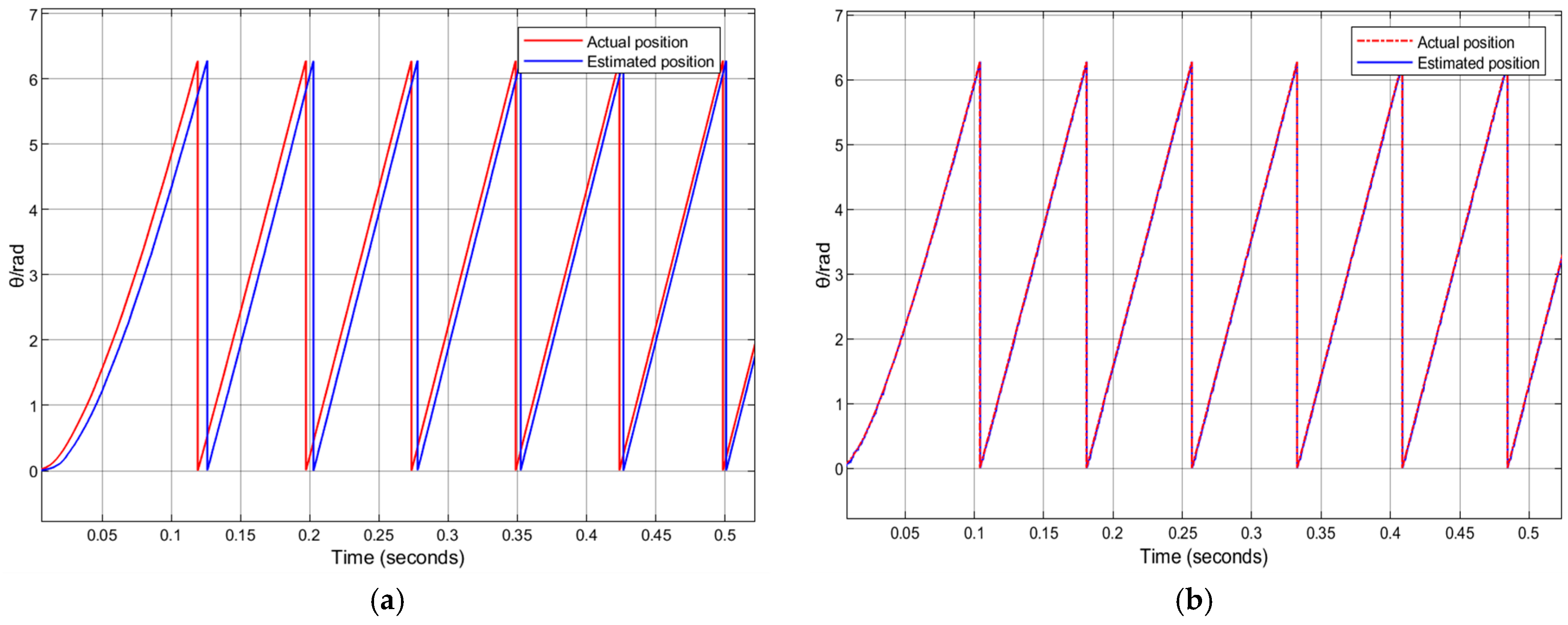
Figure 13 is a comparison chart of the estimated position and actual position between the PI Phase-Locked Loop and the improved ESO Phase-Locked Loop during the loaded start-up process, including two subgraphs: (a) PI-PLL and (b) ESO-PLL. In
Figure 13a, there is an obvious deviation between the estimated position curve and the actual position curve of PI-PLL, and the two curves are separated to a large extent especially during the start-up phase. In
Figure 13b, however, the estimated position curve and the actual position curve of ESO-PLL almost overlap. Even during the dynamic process of loaded start-up, the deviation between the two is extremely small. This fully demonstrates that ESO-PLL has better accuracy in rotor position estimation under the scenario of loaded start-up.
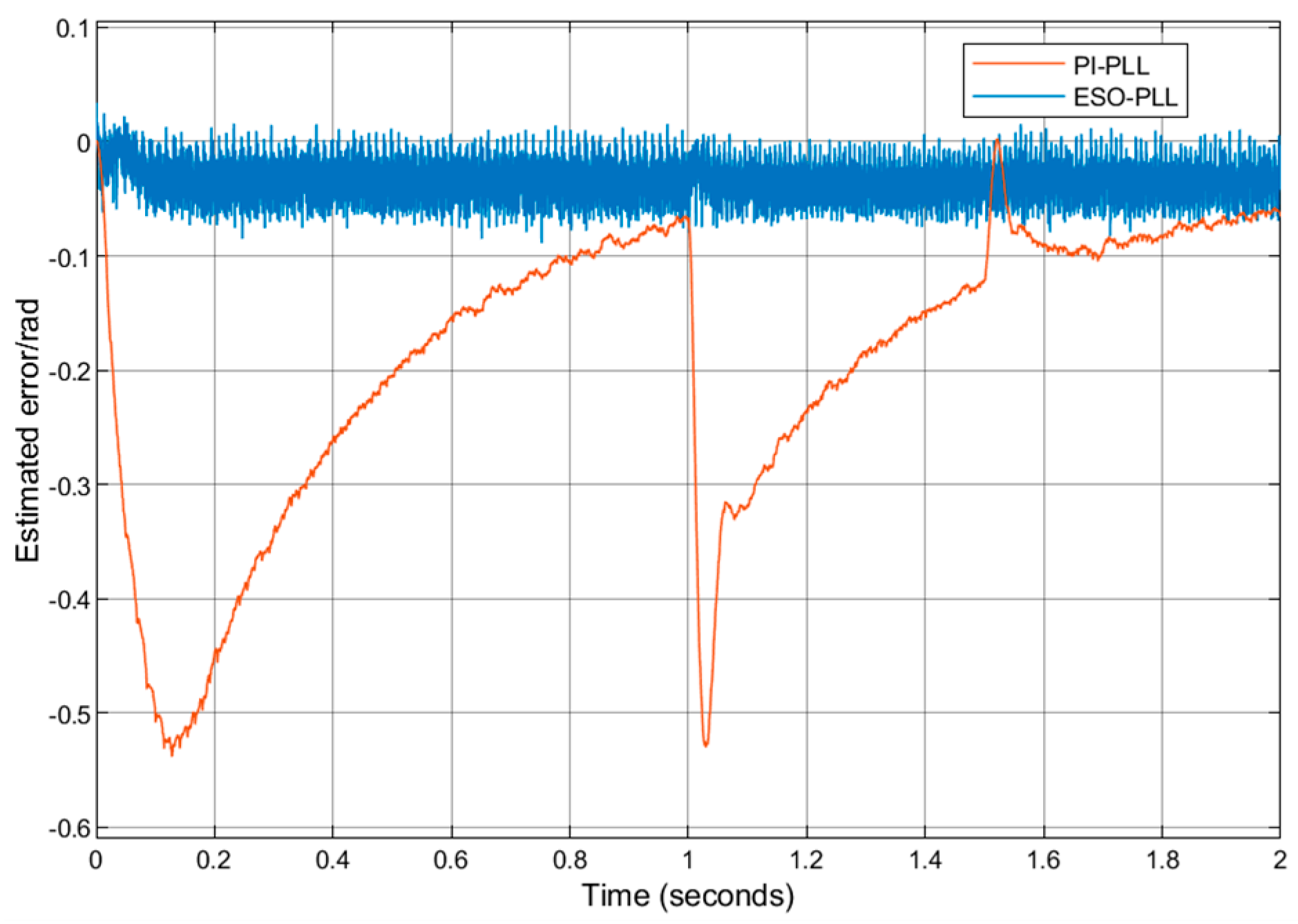
Figure 14 is a comparison chart of the estimated position and actual position errors between PI-PLL and the improved ESO-PLL. This figure further verifies the advantages of ESO-PLL: within the time interval covered by the curve, the position error of the improved ESO-PLL is always maintained within a small range and can quickly return to a state close to zero error. PI-PLL not only has a higher peak value of position error but also takes a longer time for the error to return to the stable range. This shows that the improved ESO-PLL has stronger anti-disturbance ability and better stability in speed control when dealing with changes in operating conditions.
Table 3 compares the performance of PI-PLL and ESO-PLL across different operating conditions. At 200 rpm, ESO-PLL’s speed estimation error (3.7 rpm), rotor position error (0.08 rad), and settling time (0.16 s) are all superior to PI-PLL’s (9.6 rpm, 0.54 rad, 0.26 s). At 300 rpm, ESO-PLL also outperforms PI-PLL. Under increased and reduced load scenarios, ESO-PLL maintains smaller speed and position errors and shorter settling times, demonstrating its better accuracy and robustness.
In low-speed steady-state operation, at 200 rpm, the traditional PI-PLL exhibits a speed estimation error of 9.6 rpm, a rotor position estimation error of 0.54 rad, and a settling time of 0.26 s. In contrast, the ESO-PLL reduces the speed estimation error to only 3.7 rpm, cuts the position estimation error to 0.08 rad, and shortens the settling time to 0.16 s—optimizing the three core control indicators by approximately 61.5%, 85.2%, and 38.5%, respectively. Even when the speed increases to 300 rpm, the PI-PLL still has a speed error of 9.2 rpm and a position error of 1.7 rad, while the ESO-PLL maintains a speed error of 3.6 rpm and a position error of 0.09 rad, consistently delivering superior steady-state estimation accuracy. Moreover, this speed control method is not suitable for high-speed operating conditions. At high speeds, the back electromotive force (back-EMF) of the motor increases and its frequency rises accordingly. This leads to strong coupling between the high-frequency injected signal and the back-EMF. Since the high-frequency injected signal is originally intended to obtain the motor rotor position information, such coupling will cause distortion of the injected signal, thereby affecting the accurate detection of the rotor position and consequently impairing the control performance. Additionally, during high-speed operation, the electromagnetic noise and mechanical vibration noise generated by the motor increase. These noises interfere with the high-frequency injected signal, further reducing the signal-to-noise ratio and making position detection based on high-frequency injections more difficult, which also affects the performance of the control system at high speeds.
When the load increases, the PI-PLL’s speed estimation error rises to 10.5 rpm, with a position estimation error of 0.56 rad and a settling time of 0.18 s. However, the ESO-PLL keeps its speed error at 3.9 rpm, position error at 0.1 rad, and settling time at 0.16 s, showing better error control and response speed. When the load decreases, the PI-PLL’s speed error surges to 11.4 rpm, position error reaches 1.9 rad, and settling time extends to 0.29 s. Meanwhile, the ESO-PLL remains stable, maintaining a speed error of 4.1 rpm, a position error of 0.1 rad, and a settling time of 0.17 s.
As shown in
Figure 15, at a speed of 50 rpm, the speed regulation of the PI-PLL—based control system fails due to the extremely low signal-to-noise ratio of the high-frequency signal, and the ESO-PLL also inevitably exhibits speed fluctuations.
Moreover, this speed control method is not suitable for high-speed operating conditions. At high speeds, the back electromotive force (back-EMF) of the motor increases and its frequency rises accordingly. This leads to strong coupling between the high-frequency injected signal and the back-EMF. Since the high-frequency injected signal is originally intended to obtain the motor rotor position information, such coupling will cause distortion of the injected signal, thereby affecting the accurate detection of the rotor position and consequently impairing the control performance. Additionally, during high-speed operation, the electromagnetic noise and mechanical vibration noise generated by the motor increase. These noises interfere with the high-frequency injected signal, further reducing the signal-to-noise ratio and making position detection based on high-frequency injections more difficult, which also affects the performance of the control system at high speeds.
5. Conclusions
This study focuses on the speed chattering problem of permanent magnet synchronous motors (PMSMs) caused by high-frequency square wave injection in the low-speed operation range (200–500 r/min). It aims to improve the rotor position estimation accuracy, anti-harmonic interference capability, and anti-sudden load change capability of sensorless control systems, thereby optimizing the low-speed control performance of traditional control schemes and meeting the practical requirement for stable low-speed operation of motors.
Through theoretical analysis and simulation verification, the study has obtained three core findings. Firstly, the traditional PI phase-locked loop (PI-PLL) is susceptible to high-order harmonic interference when demodulating high-frequency square wave injection signals, leading to periodic deviations in rotor position estimation and ultimately causing speed fluctuations. In contrast, the extended state observer phase-locked loop (ESO-PLL) can uniformly classify the system’s unmodeled dynamics, external load disturbances, and harmonic interference as “total disturbances”. By real-time estimating and compensating for these disturbances, it significantly reduces position estimation errors and effectively suppresses the impact of sudden load changes on the system. Secondly, the dynamic pole placement strategy designed for the speed loop can adaptively adjust the controller parameters according to the motor’s operating states (loaded/unloaded, steady-state/transient). During transient phases such as start-up and speed switching, large poles are adopted to accelerate the response speed; during the steady-state phase, small poles are switched to reduce operating errors; and during the transition phase, a smooth attenuation function is used to achieve stable parameter switching, balancing the system’s dynamic response speed and steady-state control accuracy. Thirdly, by injecting high-frequency square wave voltage signals into the dq axes of the rotating coordinate system and combining signal demodulation with ESO-PLL technology, the decoupling of high-frequency response currents can be realized, and effective rotor position information can be successfully extracted from the current signals containing interference, providing support for accurate sensorless control.
From the perspective of technical significance, the “ESO-PLL + dynamic pole placement” cooperative control strategy proposed in this study breaks through the bottlenecks of traditional high-frequency square wave injection-based sensorless control in two aspects: disturbance suppression and parameter adaptability. Without additional hardware costs, it can solve the problems of harmonic interference and load disturbance in the low-speed range only through algorithm optimization, significantly improving the accuracy and robustness of PMSM sensorless control. From the perspective of application value, this strategy can be directly applied to PMSM control systems that require stable low-speed operation, providing a reliable solution for the promotion and application of sensorless control technology in low-speed precision fields (such as precision transmission, low-speed conveying equipment, etc.), and also offering theoretical and practical references for the subsequent optimization of low-speed control algorithms for similar motors.

