Article

Design and Gait Simulation Study of Wheel-Legged Conversion Device Used in Hexapod Bionic Robot

1
School of Mechanical and Automotive Engineering, Liaocheng University, Liaocheng 252000, China
2
Research Institute of Aerospace Technology, Central South University, Changsha 410083, China
3
Liaocheng Real Estate Registration Center, Liaocheng 252000, China
*
Author to whom correspondence should be addressed.
Processes 2025, 13(10), 3364; https://doi.org/10.3390/pr13103364
Submission received: 12 September 2025 / Revised: 15 October 2025 / Accepted: 15 October 2025 / Published: 21 October 2025
(This article belongs to the Section Biological Processes and Systems)

Abstract

By emulating the morphological structures of organisms, bionic robots achieve enhanced locomotion efficiency, stability, and environmental adaptability. Inspired by insect morphology and biological locomotion mechanisms, a wheel-legged transformation device for a hexapedal robot is proposed in this work. First, an iris-type wheel-legged transformation mechanism is designed. Subsequently, the operational principle of the iris–link composite mechanism is analyzed, and kinematic modeling of the transformation process is conducted. Finally, joint angle rotation, positional variation, and their effects under different gait states are examined through simulation of three typical gait patterns. Experimental results demonstrate that the proposed design significantly improves the motion stability of the bionic hexapedal robot. Furthermore, the adoption of a hollow leg structure reduces weight while enhancing locomotion flexibility, thereby strengthening the robot’s overall capability to respond to external disturbances. In summary, this study offers a valuable reference for the future development of wheel-legged transformable bionic robots.

1. Introduction

Bionic robots have strong environmental adaptability [1]. This kind of robot has strong terrain traffic ability to work efficiently and steadily in variable environments through imitating the morphological structure and movement mode of the organisms. However, it is usually relatively simple in the movement nature of traditional multi-footed robots [2]. For example, wheeled robots can only adapt to low-complexity terrain such as flat ground and slopes, and their movement efficiency will be greatly reduced in encountering rugged complex situations. Despite the fact that the legged robot can adapt to complex terrains, its movement speed is relatively slow and its energy efficiency is much lower than that of wheeled structures on flat roads under the same circumstances [3,4,5]. As a result, it is of a great significance in the design requirements for a wheel-legged conversion device.
Existing research has mostly focused on bipedal or quadruped configurations, with limited exploration in the field of hexapod wheel-legged robots, in the wheel-legged conversion of a multi-legged robot [6]. For example, Wang et al. [7] propose a motion selection strategy based on reduced-order models for a leg-wheel transformable robot. Bledt et al. [8] introduced the key design principles and control architecture of driving Cheetah and Spot robots, especially their high-performance leg design and high-frequency control loop. These technologies are also applied and extended to their hybrid platform. Zhang et al. [9] reveal design principles through the study of obstacle performance and tipping stability of a novel wheel–leg deformation mechanism. Chen et al. [10] present a novel leg-wheel module with fast transformation and leaping capabilities, showcasing potential advancements in wheel-legged robot design. The study by Li et al. [11] focuses on the design and analysis of a mobile robot with a transformable wheel-legged mechanism, shedding light on the structural considerations for enhanced performance. Additionally, Cao et al. [12] investigate mechanism design and dynamic switching modal control of a wheel-legged separation quadruped robot, highlighting the importance of adaptive control strategies for improved operational efficiency.
In order to further enhance the performance and broaden the applicability of wheel-legged robots, researchers have delved into optimizing their functionality [13,14,15,16,17,18]. Wang et al. [19] concentrate on designing a deformable wheel-legged robot utilizing origami mechanisms, showcasing the incorporation of innovative structural components to enhance its capabilities. Li et al. [20] present a study on generating safe trajectories for a wheel–leg hybrid mechanism through discrete mechanics and optimal control, emphasizing the crucial role of safety considerations in diverse operational contexts. The research by Raturi et al. [21] explores the dynamic behavior of a slider crank mechanism-based wheel-legged mobile robot, providing insights into the mechanical interactions that influence its performance. Park et al. [22] offer a comprehensive review on transformable wheels, providing valuable insights into mechanism classification and analysis based on mechanical complexity. However, further research is essential to establish a standardized framework for evaluating the mechanical performance of transformable wheels in wheel-legged robot systems. Additionally, Zhao et al. [23] delve into modeling and stability control of steering and reconfiguration motion for wheel-legged metamorphic robots, highlighting the importance of adaptive control strategies for versatile locomotion capabilities. The integrated wheel–foot–arm design proposed by Du et al. [24] represents a novel approach to enhance the mobility and versatility of mobile platforms. Kim et al. [25] present a type synthesis and kinematic analysis of a 2-DOF shape-morphing wheel mechanism tailored for step-overcoming tasks. While this study contributes to innovative mechanism design for enhanced mobility, further exploration is needed to assess the practical application and scalability of such shape-morphing mechanisms in real-world settings. Furthermore, Comin and Saaj [26] investigate slip estimation and soft terrain characterization with multi-legged wheel-legs, underscoring the importance of terrain adaptability. Nevertheless, additional research is required to optimize slip control strategies for improved traction and stability on challenging terrains. Li et al. [27] conduct a comprehensive study on the design, analysis, and experimentation of a wheel-legged mobile robot, showcasing the integration of theoretical insights into practical applications. Qiao et al. [28] propose a wheel-legged robot with an active waist joint, highlighting advancements in mechanical design and control integration. Won et al. [29] focus on the design optimization of a linkage-based 2-DOF wheel mechanism for stable step climbing, stressing the significance of mechanical optimization for locomotion tasks. Additionally, Shin et al. [30] undertake a comparative analysis of tail shapes in tri-wheel-based stair-climbing robots, underlining the importance of tail design on climbing performance.
Based on preliminary investigations, significant progress has been made in the field of wheel-legged hybrid robots. However, while existing research has primarily focused on bipedal and quadrupedal configurations, hexapod wheel-legged robots remain considerably underexplored. To address this gap, this study is devoted to the development of a bionic hexapod robot aimed at enhancing its motion smoothness, agility, speed, and terrain adaptability. A major challenge in this endeavor is that robots with heavy mechanical structures often struggle to perform highly dynamic motions, such as jumping and rapid posture adjustment. In this context, the adoption of hollow lightweight materials offers notable advantages, including reduced inertia, lower energy consumption, and extended operational endurance [31,32]. Accordingly, this study employs a hollow biomimetic structural design, which effectively reduces the overall weight of the robot. By mimicking biological forms and motion patterns, the robot’s operational efficiency is further improved. To enable seamless dual-mode locomotion, a simple and reliable transformation mechanism has been designed. This mechanism integrates an iris structure with a linkage system to achieve rapid retraction and deployment of the wheels, ensuring fast and accurate switching between wheeled and legged modes. Simulation results demonstrate high consistency between the wheel–leg transition mechanism and the planned gait across three different gait patterns. Finally, by using image detection techniques, the angle variations have been collected for each joint during the startup, movement, and stopping phases of the hexapod robot prototype. Then a dynamic analysis was conducted on these data by using corresponding analysis software, which demonstrated the rationality and accuracy of the design. This coherence enhances the programmability of the gait, improves the flexibility of the hexapod bionic robot’s motion, and strengthens its adaptability to varying ground geometries.

2. The Basic Idea of Design

Bionics, or biologically inspired engineering, has been increasingly adopted as a fundamental paradigm for innovation in robotics [33]. As the core locomotion unit of a wheel-legged transformable bionic hexapod robot, the biomimetic hexapod structure is designed based on the morphological characteristics and motion mechanisms of insect legs. In nature, insect thoraxes are often elliptical or rectangular—a shape refined through evolution to maximize motion efficiency, as illustrated in Figure 1a. The proposed bionic structure is composed of a body frame and multiple three-degree-of-freedom (3-DOF) leg mechanisms. The body frame is designed as a simple rectangular structure, inspired by the insect thorax. This longitudinally symmetrical configuration ensures overall stability and balance, while rationally allocated leg mounting points provide sufficient rotational space for leg movement. Each 3-DOF leg provides yaw, pitch, and rotational motions, significantly enhancing the robot’s adaptability and flexibility in complex environments. The integrated design incorporates a hollow bionic leg structure, a motor-driven omni-directional wheel assembly, and an iris-based wheel–leg transformation mechanism. The operational principle of the iris–link composite mechanism is analyzed, and a kinematic model of the transformation process is established. Furthermore, joint angle rotation and positional variation under various gait states are examined through simulations of three typical gait patterns. The results demonstrate that the proposed wheel–leg transformation device substantially improves the motion stability and complex terrain adaptability of the bionic hexapod robot.

3. Materials and Methods

3.1. Design and Analysis of Bionic Hexapod Structure

As the core locomotion unit of the wheel–leg transformation device, the bionic hexapod structure is designed based on the morphological characteristics and biomechanical motion mechanisms of insect legs. In nature, a three-degree-of-freedom (3-DOF) configuration is commonly adopted in the leg structure of insects. Each leg is composed of three linkages—the coxa, femur, and tibia—corresponding to the hip, thigh, and knee segments, as illustrated in Figure 1b.
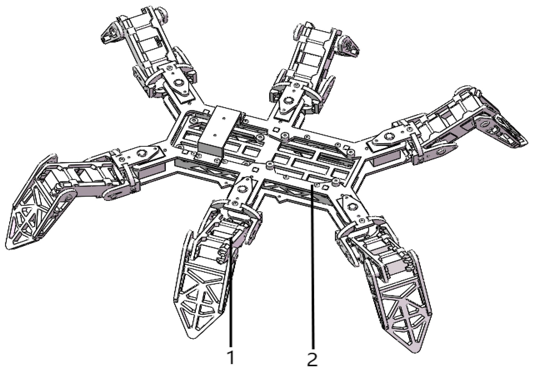
As illustrated in Figure 2, the bionic hexapod structure comprises a torso frame and six three-degree-of-freedom (3-DOF) leg mechanisms. The torso is designed as a simple rectangular frame, a configuration inspired by the insect body, which provides longitudinal symmetry to ensure overall stability and balance. Furthermore, the leg mounting positions are strategically allocated to maximize rotational space for each leg. Each 3-DOF leg is capable of yaw, pitch, and rotational motions, thereby significantly enhancing the robot’s adaptability and flexibility in complex environments.

3.2. Design of the Wheel-Legged Conversion Mechanism

3.2.1. Three-Degree-of-Freedom Leg Structure

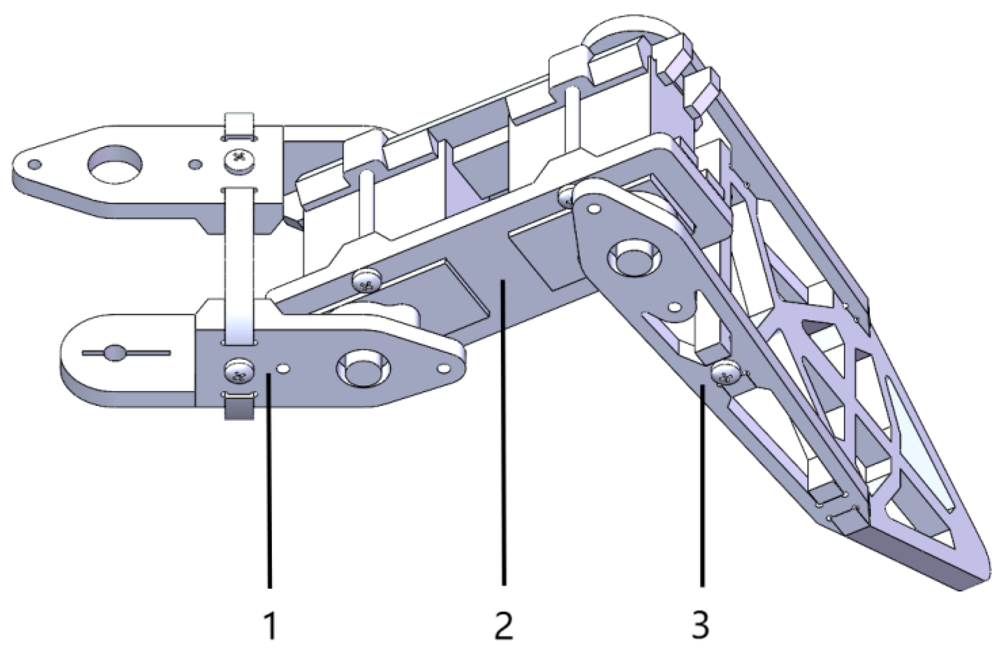
As shown in Figure 3, the three-degree-of-freedom leg structure comprises a base joint fixture, a thigh joint fixture, and a shin joint fixture.

3.2.2. Establishment of Kinematic Model

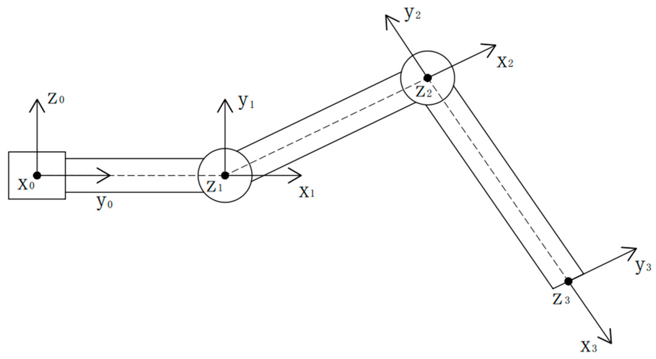
In the analysis of coordinate systems, a fixed coordinate system is conventionally defined on each link to describe its relative positional relationship with adjacent links. As a conventional approach, the standard Denavit–Hartenberg (D-H) parameter method [25] is adopted to establish a coordinate system for each joint of the robotic arm, thereby providing a clear and intuitive representation of the interrelation and pose of all joints in the three-axis robotic arm, as illustrated in Figure 4. The dashed lines in the figure represent the symmetry center lines of each rod.
Based on the coordinate system established in the above figure, the parameter values of each link are derived according to the D-H convention, so a D-H parameter table is established as shown in Table 1. Relevant analysis is conducted using the MATLAB Robotics Toolbox (version 2018b). In this design, the range of link length is taken as 25–40 mm, and the range of joint is taken as approximately 0.1–0.3 mm, which meets the joint clearance parameter of standard D-H based on industry standards.

3.2.3. Finite Element Analysis of the Three-Degree-Freedom Leg

Based on its capabilities as a powerful numerical computational technology, the finite element method is employed to analyze the static and dynamic performance of structures by discretizing a complex continuum into an assembly of finite simple elements [34,35,36]. Subsequently, this method is applied to conduct a mechanical analysis of the three-degree-of-freedom leg structure.
(1)
Solid Model Parameters of Leg’s Finite Element Analysis (version ANSYS 12.0)
The wheel-legged conversion bionic hexapod robot is held by six legs to support its overall mass when working in legged state. However, in reality, due to the irregular distribution of other structures, the forces on the six legs are not completely the same. Therefore, an analysis is conducted on the leg that experiences the highest force in the extreme state of load.
The fixture location and details are set for the assembly model of single leg. The torque working in the position of each servo motor on the leg and the load on the surface of the remaining components have also been set at the same time. In order to ensure the normal operation of the device, the material and strength of the leg need to be able to support the weight of the whole vehicle. The ABS material is selected here.
A solid grid is generated by a high-quality grid with 16 Jacobian points as shown in Table 2. When conducting the finite element analysis on the leg, only the coxa and the tibia joint fixture need to be analyzed because the installation positions of the thigh joint and knee joint servo are both on the thigh joint, and the rotation of the servo exerts force on the coxa and tibia joint.
(2)
Results of static analysis
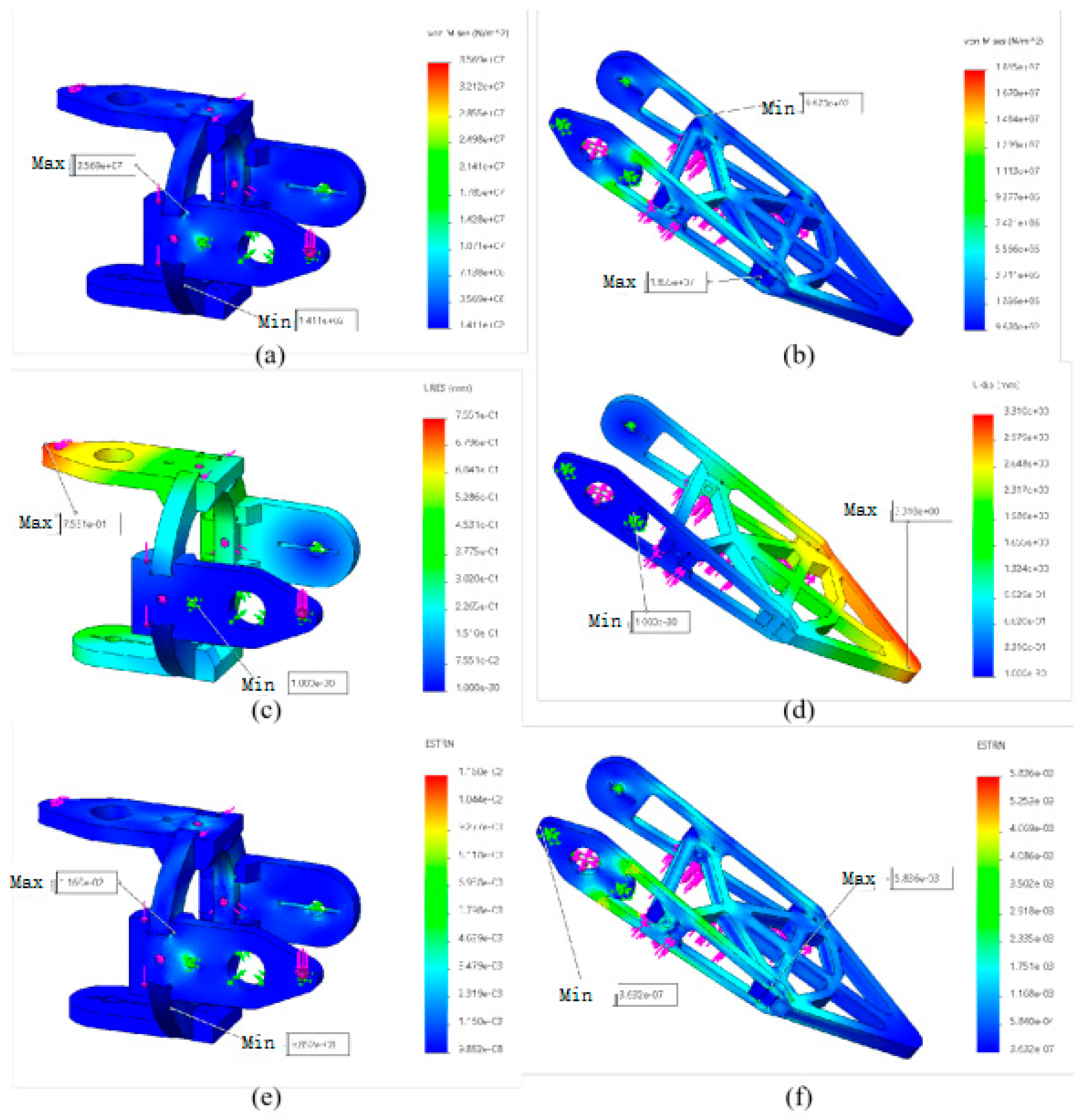
As shown in Figure 5, in the analysis process of the coxa joint and the tibia joint fixture, the maximum yield stress of the coxa joint fixture is 3.569 × 10⁷ N/m2, which meets the requirement of an ultimate yield stress of 5 × 10⁷ N/m2. The maximum yield stress of the tibia fixture is 1.855 × 10⁷ N/m2, which meets the requirement of an ultimate yield stress of 5 × 10⁷ N/m2.
The maximum displacements of the coxa joint and the tibia joint fixture are 7.551 × 10⁻¹ mm and 3.31 mm, respectively, which is within the range of variation. The maximum strain values are 1.160 × 10⁻² mm and 5.836 × 10⁻³ mm, respectively, which are within the range of material strain variation. The range of stress variation mentioned above also conforms to the maximum yield stress limit. Therefore, it is concluded that the support plate meets the working requirements and the stress meets the requirements when the device is in operation.

3.3. Design and Analysis of Wheel

3.3.1. Scheme Design of Omni-Directional Wheel

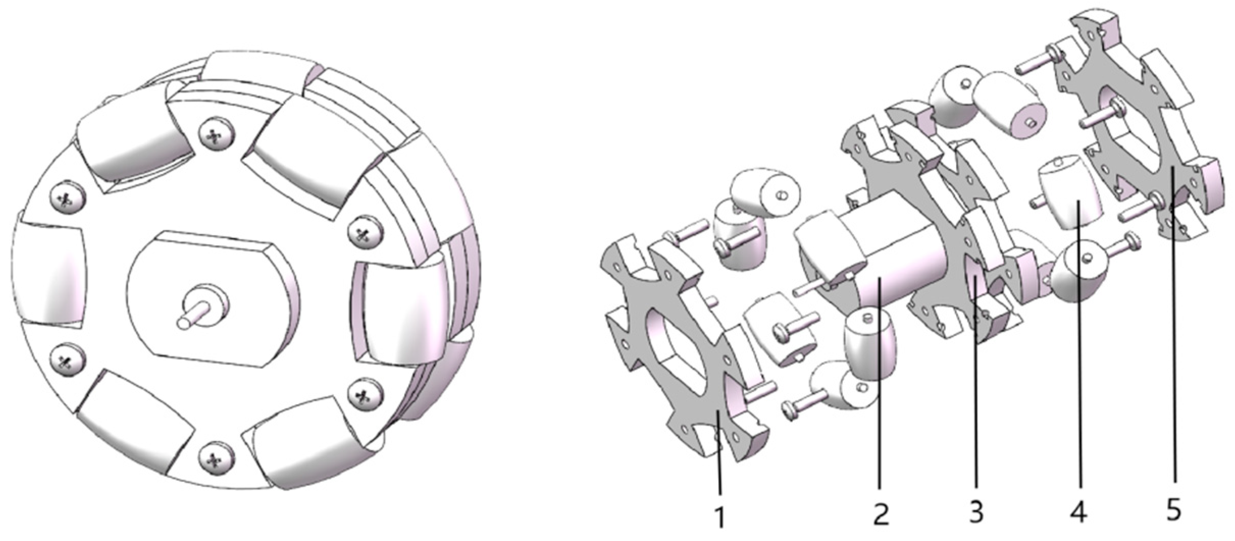
Traditional wheels can only move forward or backward. Steering requires differential rotation of the wheels, which maybe changes the direction of the wheels. However, the robots are usually allowed to move horizontally, vertically, and even rotate in place without rotating the body by omni-directional wheels. The feature of omni-directional wheels is the installation of multiple freely small rollers around the hub (this design adopts a 90° arrangement), as shown in Figure 6. These small rollers can roll independently when in contact with the ground, enabling movement of the wheel in multiple directions. Based on these advantages, the omni-directional device is designed with a motor.

3.3.2. Analysis of the Motion Mode of Omni-Directional Wheels

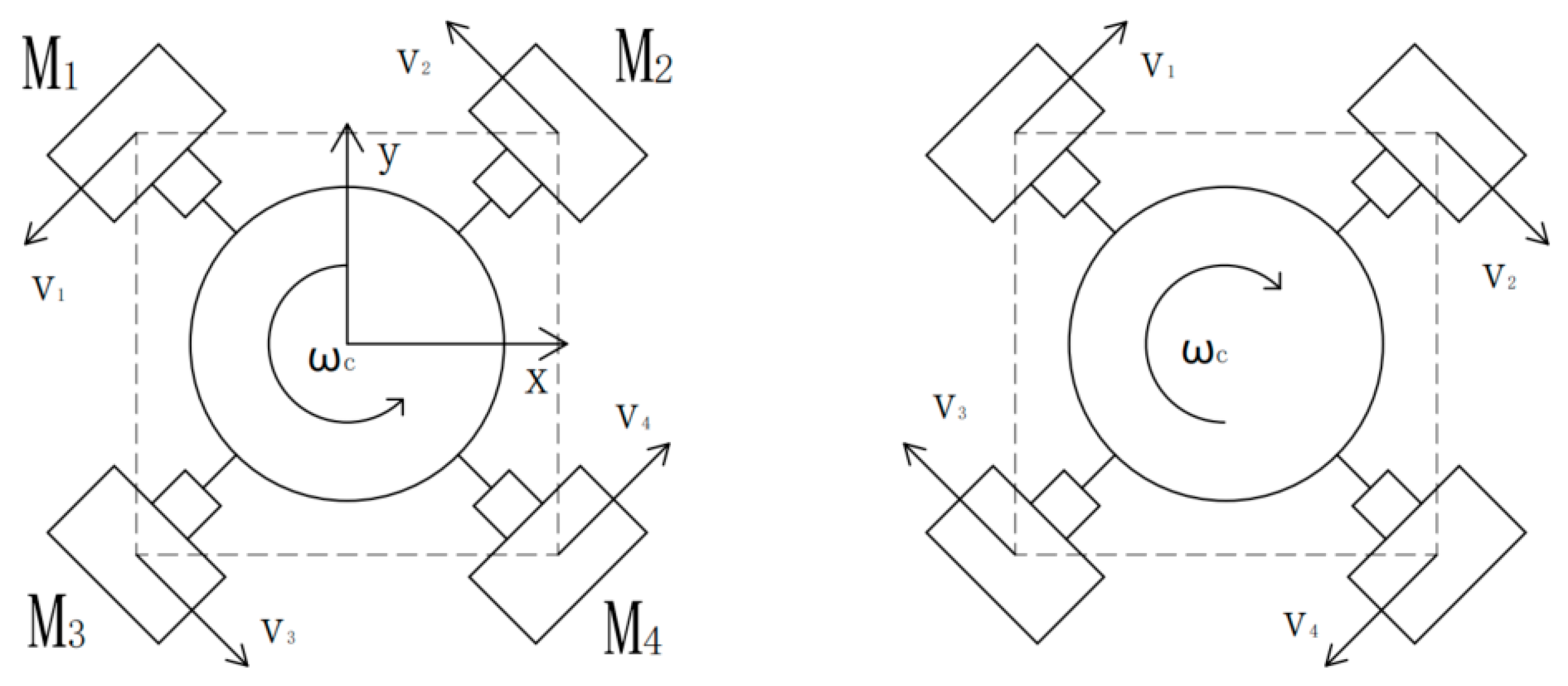
Analyzed in the four diagonal directions (left front, left rear, right front, and right rear), as shown in Figure 7, the aforementioned straight mode needs four motors to work simultaneously due to the layout characteristics of the wheels. Only two corresponding motors are required to work simultaneously in the diagonal motion mode. That is to say, it is only required to move along the direction of rotation driven by motors. The motion patterns of the four diagonal modes have been shown in Table 3. Forward rotation is indicated by +, while reverse rotation is indicated by −, and standstill is naturally indicated by 0.
In addition to the eight straight-line methods mentioned above, the rotation of the omni-directional wheel platform can also be achieved by the motor directions being allocated reasonably under the condition that the speeds of the four motors remain the same. As shown in Figure 8, among them, M represents the torque of the four steering wheels, respectively, and it is only necessary to make the directions of the four motors the same. If they are all rotating in reverse, it naturally can be rotated counterclockwise by the omni-directional wheel platform, while it can definitely be rotated clockwise in the condition where all the motors rotate in the forward direction.

3.4. Scheme Design and Working Principle of the Wheel-Legged Conversion Mechanism

3.4.1. Scheme Design of Wheel-Legged Conversion Mechanism

The wheel-legged conversion mechanism is made up of two parts designed in this article, that is, an iris structure and a linkage mechanism. The iris structure enables the four wheels to retract and extend simultaneously, while the simple linkage mechanism usually facilitates the wheels folding and unfolding in order to achieve complex operations with a simplified structure.
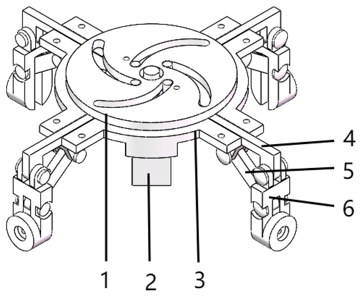
As shown in Figure 9, the wheel–leg conversion mechanism is made up of a distance-limiting plate, a steering engine, a position-limiting plate, four pushing rods, four retracting–extending rods for the wheel, and four connecting rods for the wheel. There are corresponding holes on the limiting plate, which correspond to the holes on the lower supporting plate, and the limiting plate is fixed to the lower support plate with screws. It is concentric between the distance-limiting plate and the position-limiting plate. The steering engine is located under the position-limiting plate, and its output shaft gear is concentric with the position-limiting plate. The steering engine is also fixed to the position-limiting plate with screws, and the pushing rod is clamped in the groove of the position-limiting plate. One of the ends of the pushing rod is set with a protruding cylinder, which is matched with the groove of the position-limiting plate. The linkage mechanism includes a pushing rod, wheel retracting–extending rod, and wheel-connecting rod. One end of the wheel connection rod is concentric with the other end of the pushing rod, and the other end of the wheel connection rod is used to install the output shaft of the wheel motor. The two ends of the wheel retracting–extending rod are concentric with the protruding structure on the edge of the position-limiting plate and the hole in the middle of the wheel-connecting rod, respectively. A groove is set in the middle of the retracting–extending rod to avoid collision of the motor’s output shaft when the wheel is retracted.

3.4.2. Working Principle of Wheel-Legged Conversion Mechanism

The four omni-directional wheels achieve retraction and extension by the scheme above with the wheel leg conversion mechanism through the iris structure and the linkage structure. The specific working principle is described as follows:
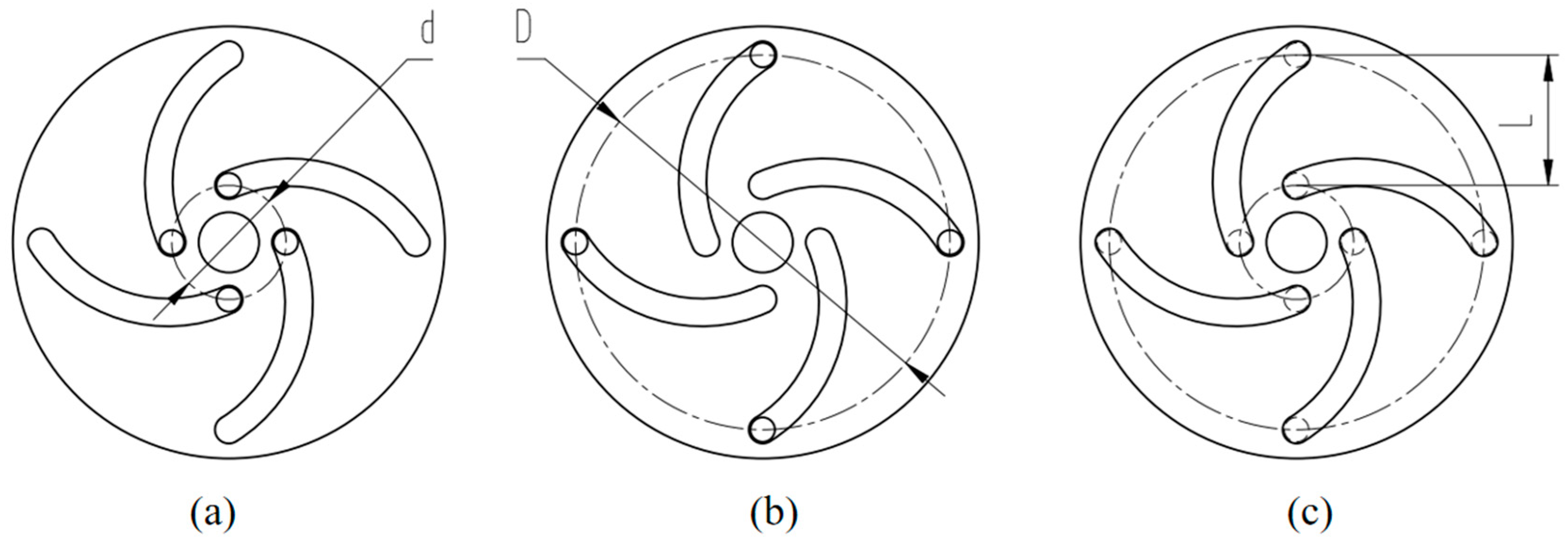
Iris structure: Assuming that the wheel is currently in a lowered state, one end of the corresponding pushing rod is located near the end in the center of the distance-limiting plate, and then the steering engine rotates to drive the distance-limiting plate to rotate counterclockwise. At this time, the protruding cylinder on the pushing rod gradually moves away from the center of the distance-limiting plate to the end of the slot, and the pushing rod moves accordingly. The motion state of the iris structure is shown in Figure 10, and the movement value of distance (L) of the pushing rod is calculated by the following formula:
L = D d 2
where D is the diameter of the circle that is located in the starting position of the protruding cylinder on the pushing rod (mm); d is the diameter of the circle where the protruding cylinder terminates on the pushing rod (mm)
M = F × L
Formula (2) indicate a direct relationship between distance of L and torque of M. Under the same load of F, the larger of L, the greater the effective torque M generated. The value of M is affected directly by the value of L. The arrows are used for dimension annotation, and dashed lines represent invisible contours.
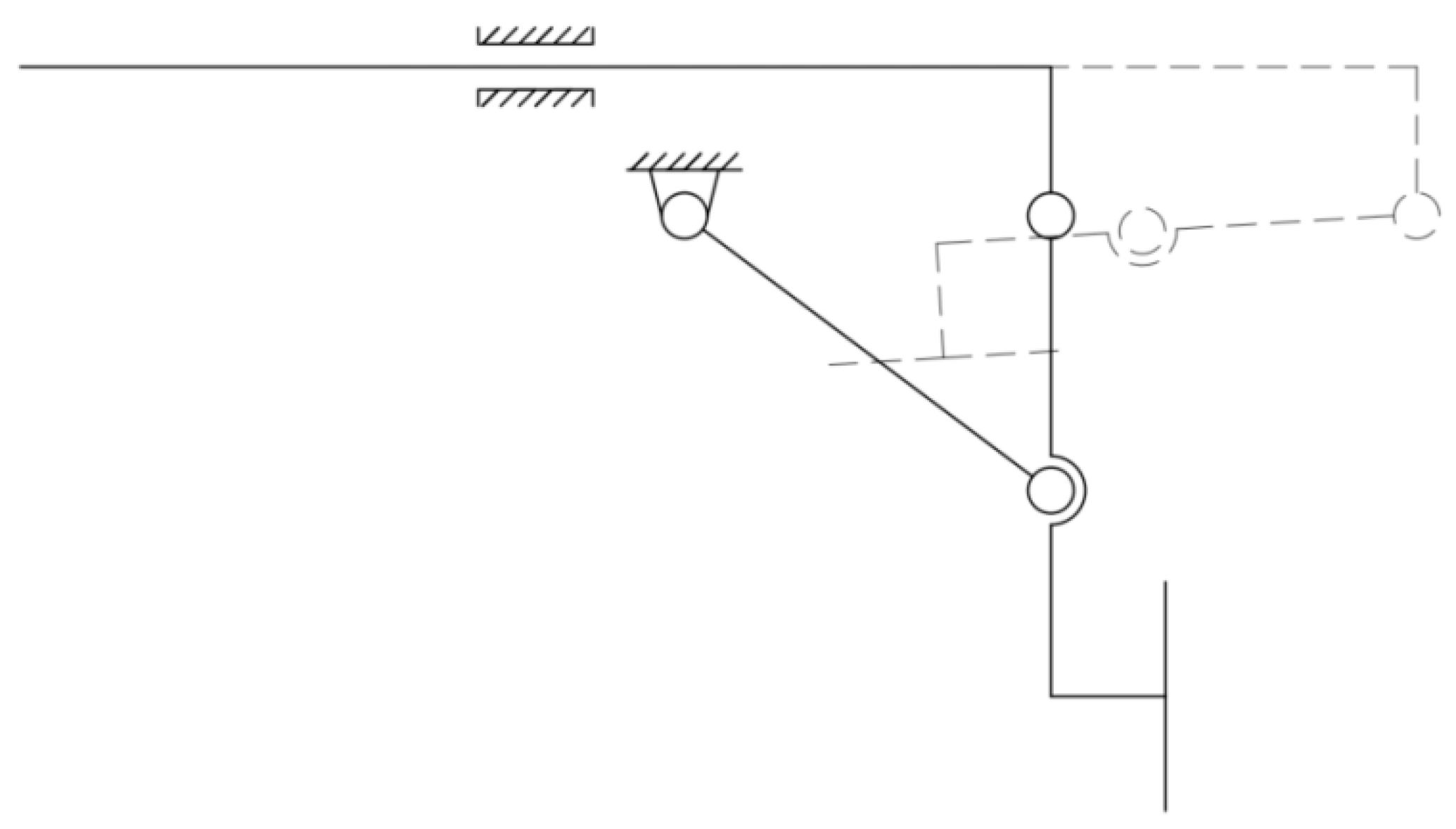
Linkage mechanism: After the pushing rod is pushed, the connecting rod of wheel rotates around the connecting shaft of the pushing rod. At the same time, retracting–extending rods for the wheel rotates around the connecting shaft of the position-limiting plate until it stops so as to retract the wheel. The two static states of the linkage mechanism are shown in Figure 11. Among them, the solid line represents the state in which the wheels are in operation; The dashed line represents the retracted state of the wheels; The circle represents the hinge.

4. Results

4.1. Construction of Simulation Environment

The leg motion of a hexapod robot was simulated and analyzed using Webots simulation software (version 2023b).
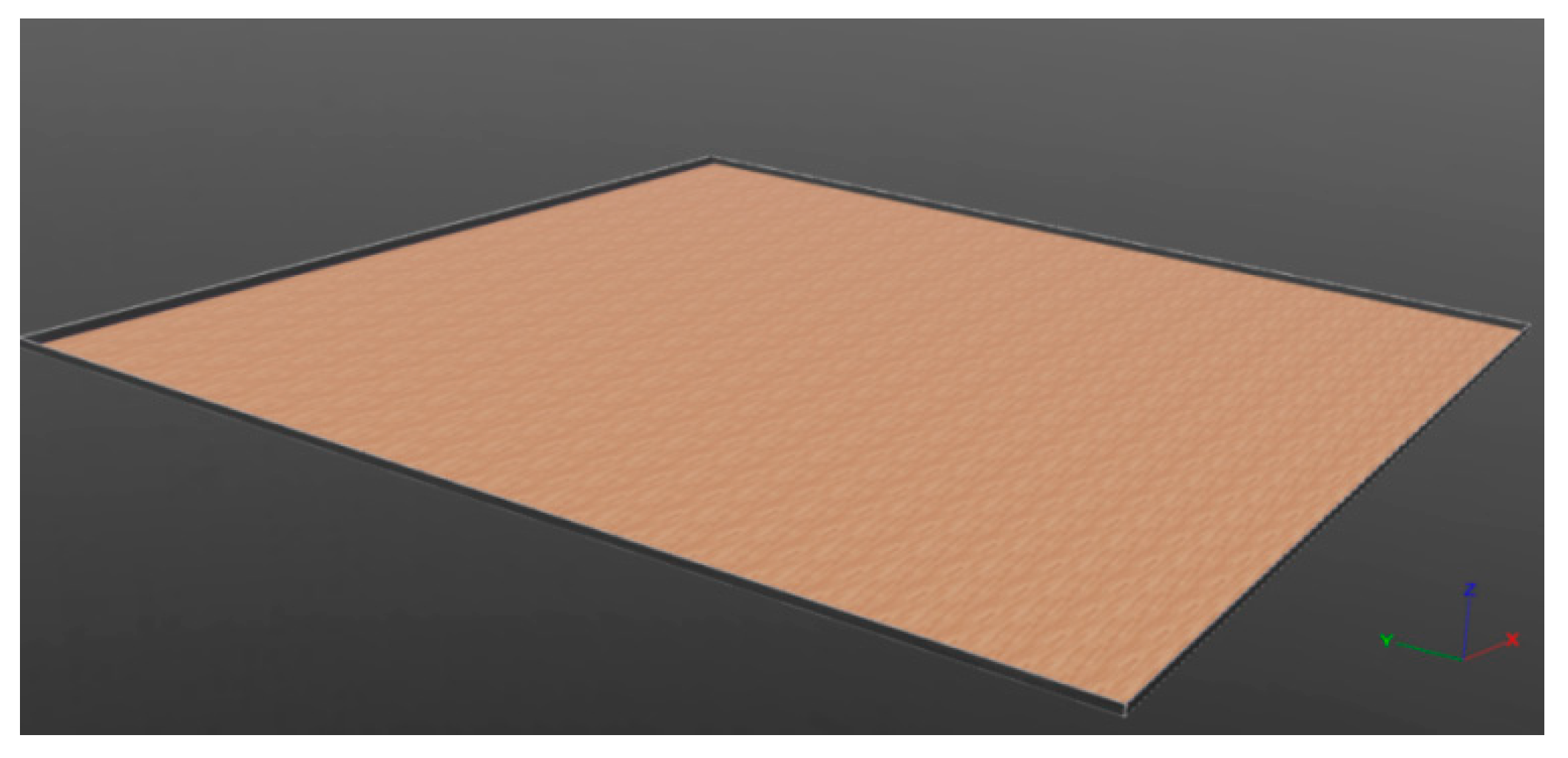
A terrain testing environment is created and a gait simulation is analyzed on flat ground in order to verify the movement patterns and stability of different gaits. The friction coefficient is set to 0.4 on flat ground to simulate a hard road surface.
The simulation scene is shown in Figure 12.
The settings of physical parameter are shown in Table 4.

4.2. Design of the Abstract Hexapod Robot

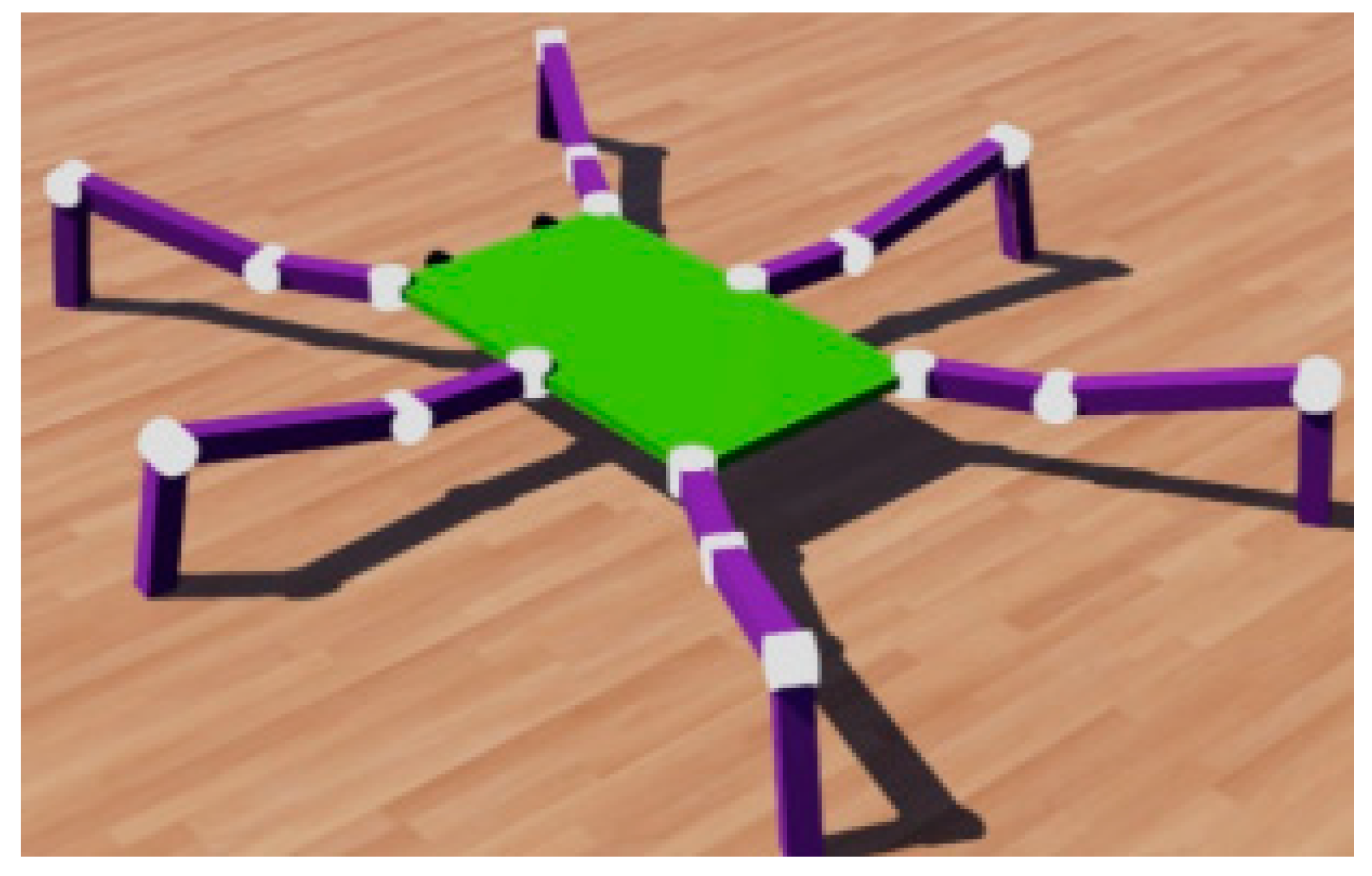
The modeling of the abstract hexapod robot is shown in Figure 13.

4.3. Planning of Typical Gait of Bionic Hexapod Robot

4.3.1. Triangular Gait

The triangular gait is an efficient gait pattern evolved by insects during movement, achieved through grouped alternating support and swinging, which can enable the robot to maintain the dynamic balance and stable progression. The six legs are divided into two groups: the support group is made up of the front one and rear one on one side and the middle one on the other side, forming a stable triangular support phase to bear the body weight; the swinging group consists of the other three legs, responsible for lifting, stepping, and landing. The specific implementation process is shown in Figure 14. The arrow represents the size, and the dashed line represents the triangular support state under different gaits.

4.3.2. Ripple Gait

The ripple gait is a highly stable gait pattern adopted by insects during movement, with which the insect’s body can be enabled to have continuous and smooth forward propulsion. It is usually characterized by the coordinated alternating swinging of both legs. The six legs are divided into three groups (Group A: left front, right middle; Group B: left middle, right rear; and Group C: left rear, right front), and movements are completed in turn by the three groups of legs, and so a “ripple-like” gait pattern has been formed in an alternating support and swing sequence. During the movement, the actions are completed by each pair of legs in the pattern of lifting, stepping, and landing. Only one pair of legs is in the swing phase at any given time, while a quadrilateral support is formed by the four legs remaining. The process of specific implementation is shown in Figure 15.

4.3.3. Wave Gait

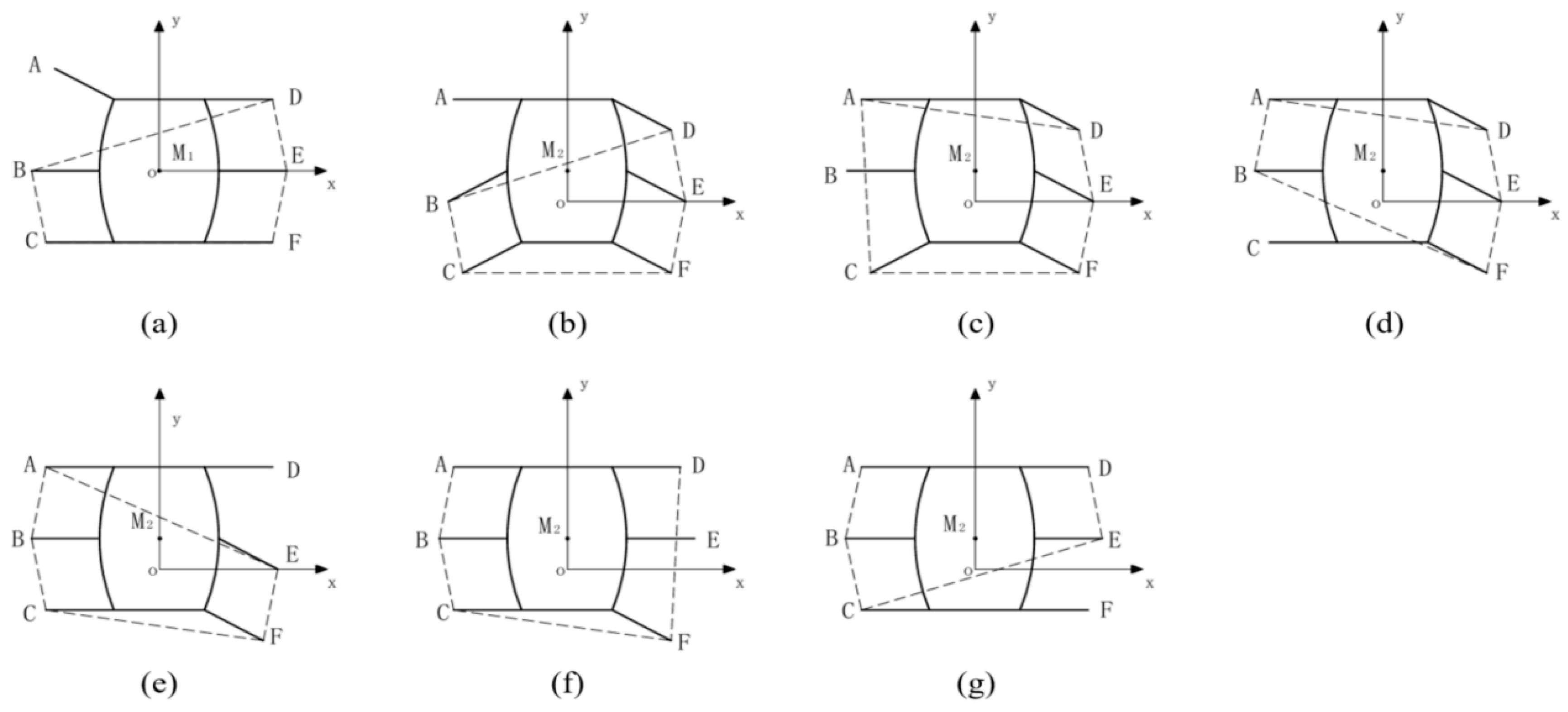
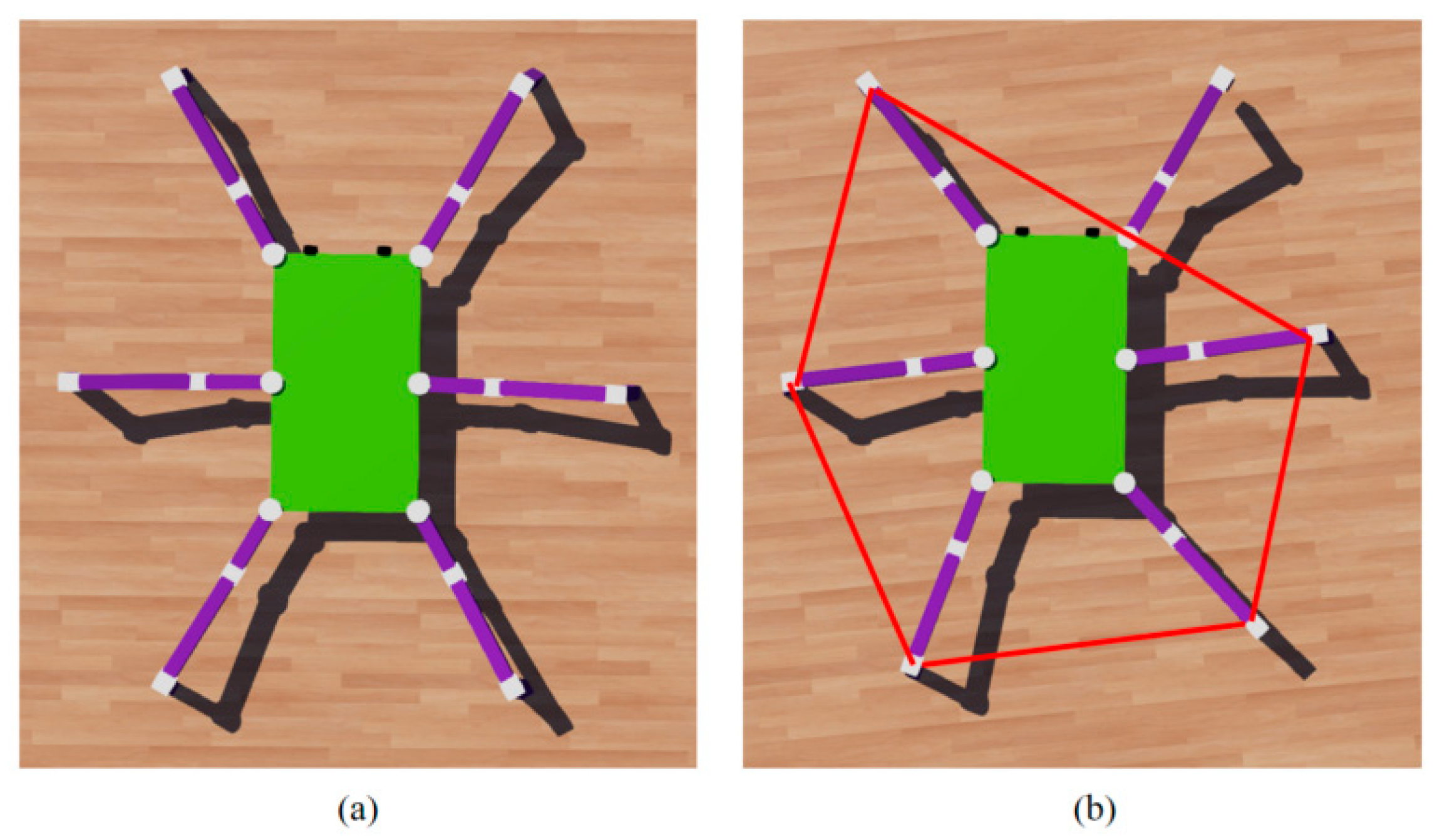
The wave gait is a high-precision movement pattern adopted by insects in narrow or unstructured environments, with which insects can be propelled forward by swinging their single leg in turn to form a continuous “wave” state. In the process, six legs are swung in a specific direction in turn. During the movement, only one leg is in the swing phase at any given moment, in order to complete the actions of lifting, stepping, and landing. Thus a pentagonal support is formed by the remained five legs to ensure that the projection of the mass center is always located in the support area. The specific implementation process is shown in Figure 16.

4.4. Simulation Experiment and Result Analysis

The constructed hexapod robot is simulated and validated with Webots.

4.4.1. Simulation of Triangular Gait

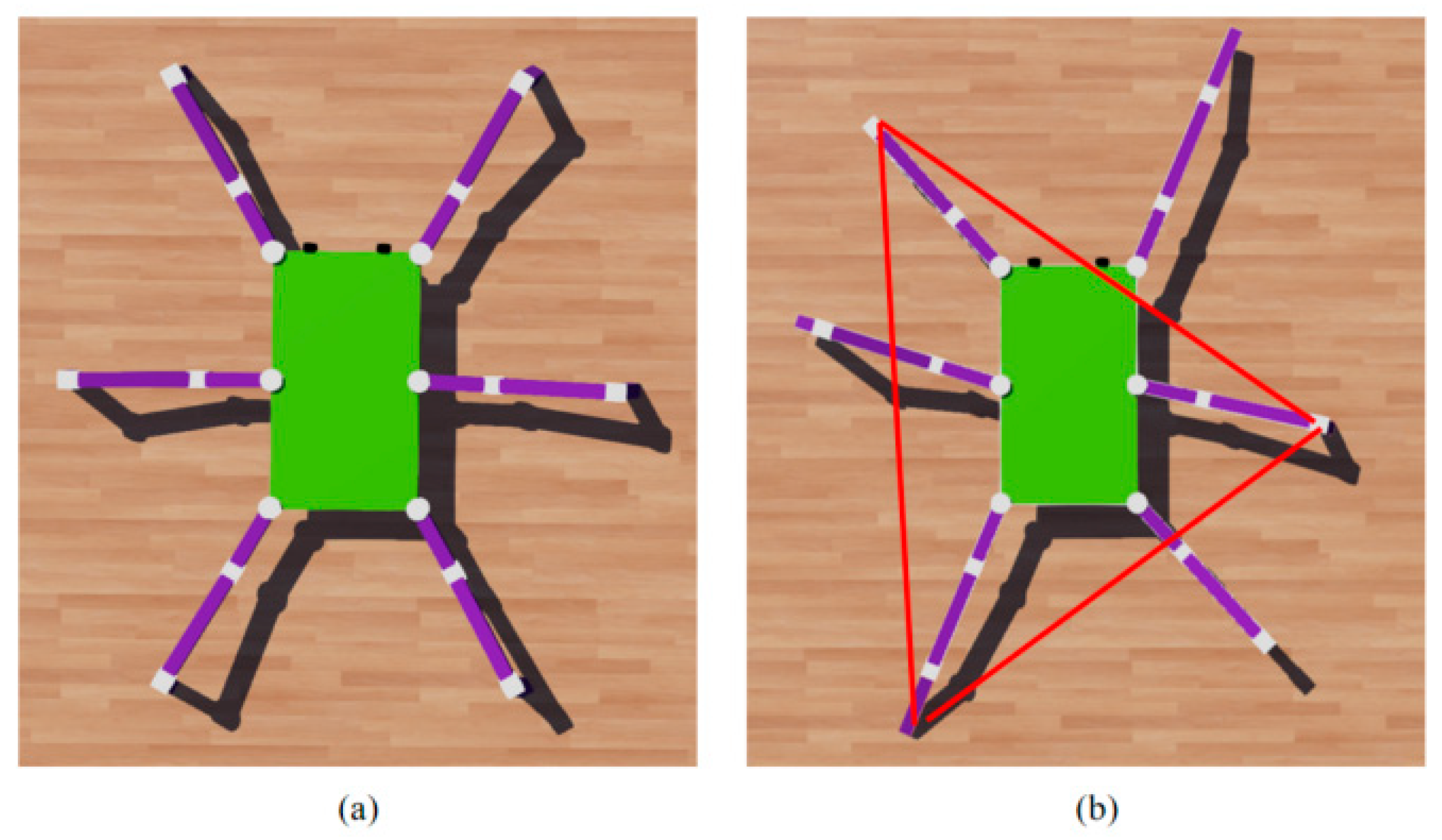
Based on the process of the triangular gait mentioned above, it can be seen from Figure 17 that the simulation process conforms to the implementation process of the triangular gait, compared with a partial-simulation schematic diagram of the triangular gait.
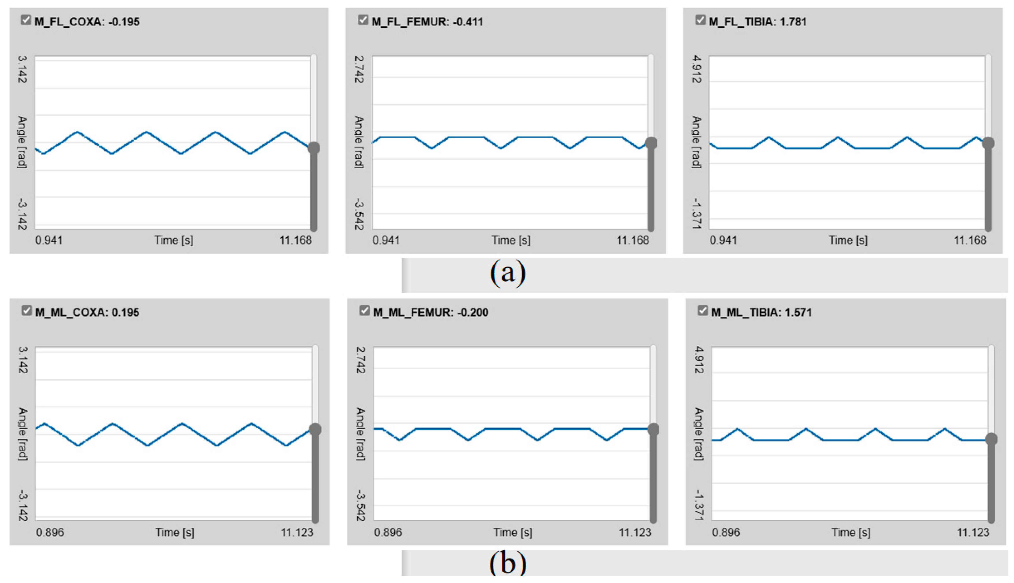
As shown in Figure 18, the triangular gait is characterized by the alternating swinging of two groups of legs. One group is constituted by the right front, left middle, and right rear, and the other group is constituted by the left front, right middle, and left rear. When the legs of one group are lifted, the other group maintains a holding position, with the holding leg fixed at the thigh joint angle. The hip joint angle of the swinging leg is consistent, and the knee joint position is reset at the moment of switching. It is shown that the thigh joints are divided into two groups, corresponding to the aforementioned groups, by the waveform diagram of each joint position sensor in the figure. The red line represents the formed support of triangular gait.
As shown in Figure 19, the joint rotation angles are observed in the hip joints. Since the rotation directions are opposite at the hip joints on the left and right sides, when one group of legs is lifted, the hip joints of these legs rotate forward. At the same time, the legs serving as the holding legs rotate backward. The joints of the lifted legs and the joints of the other group rotate in a way that the opposite sides are in the same position (the rotation directions of the left hip joints and right front ones are the same). Therefore, the rotation directions of four joints are the same in the meantime. For the thigh and knee joints, the joints in each group rotate in the same direction.

4.4.2. Simulation of Ripple Gait

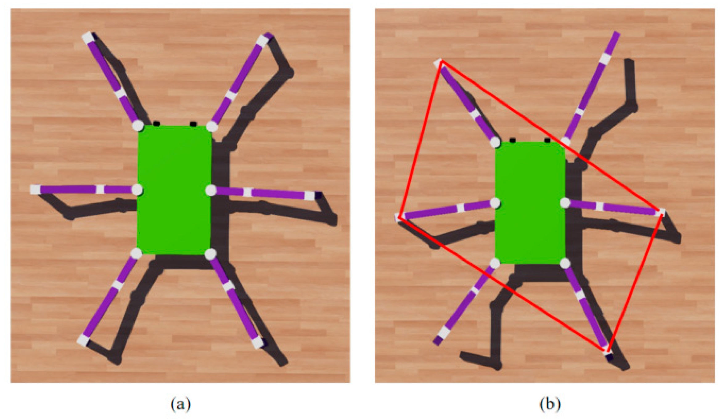
Based on the implementation process of the ripple gait mentioned above, it can be seen from Figure 20 that the simulation process conforms to the implementation process of the ripple gait by comparing it with the simulation schematic of the ripple gait. The red line represents the formed support of ripple gait.
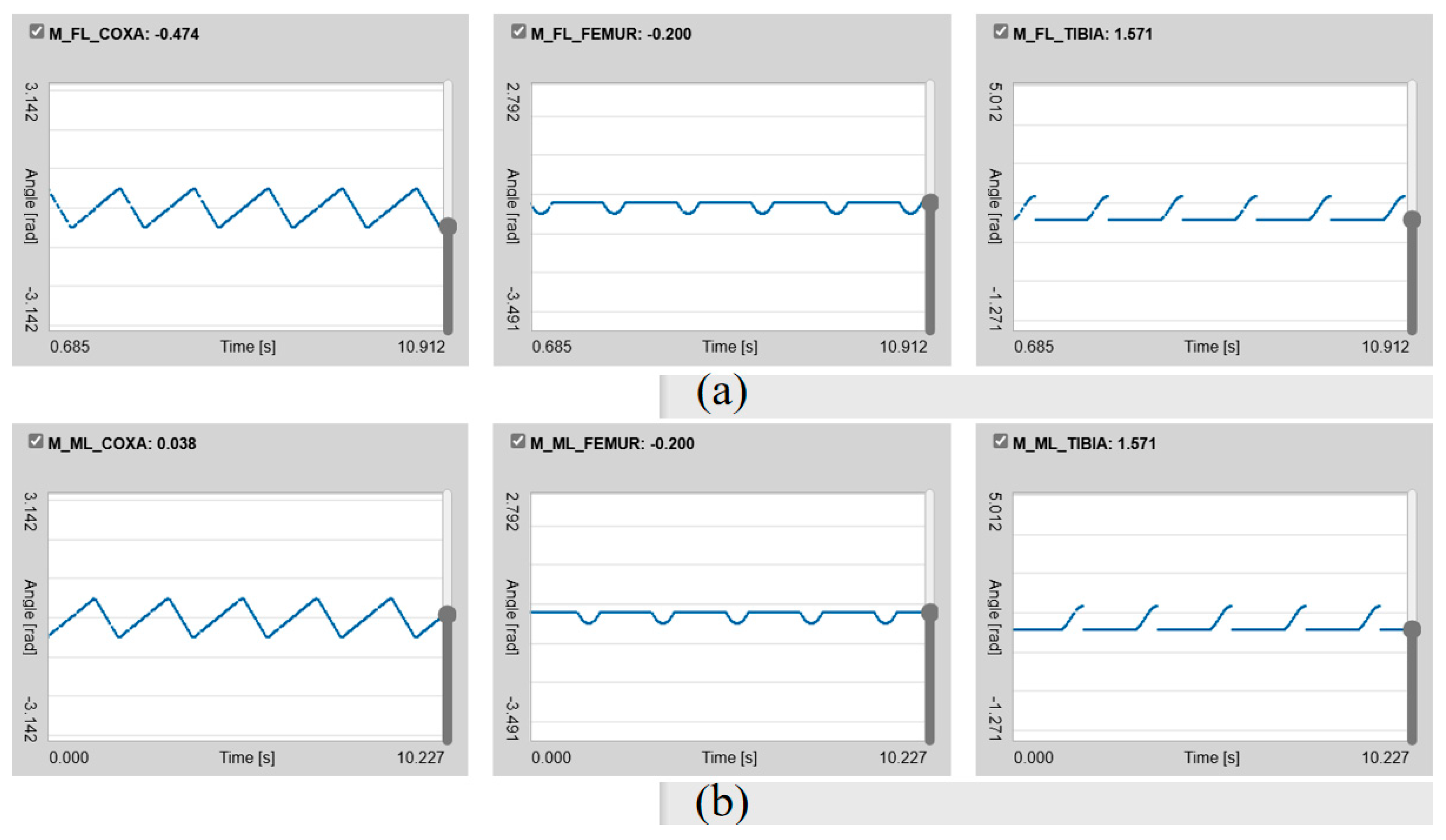
From the thigh and knee joints in the figure, it can be seen that the thigh joints are divided into three groups: left front and right back, left middle and right front, and left back and right middle, corresponding to the above planned groupings.
As shown in Figure 21, the joint rotation angle is observed for the hip joint. Since the rotation directions are opposite at the hip joints on the left and right sides, when a group of legs is lifted, the hip joints of this group of legs rotate forward. In the meantime, the legs of the holding group rotate backward. As one leg is lifted on both sides each time, the joints of the lifted leg and the ones of the other two groups of legs rotate in a manner of heterotopia with the other side (the left front leg corresponds to the right front leg and the right middle leg). There will be three joints with the same rotation direction at the same time. For the thigh and knee joints, the joints in each group are oriented in the same direction.

4.4.3. Simulation of Wave Gait

Based on the above implementation process of the fluctuating gait, it can be seen from Figure 22 that the simulation process conforms to the implementation process of the fluctuating gait, compared with the partial simulation diagram of the fluctuating gait. The red line represents the formed support of fluctuating gait.
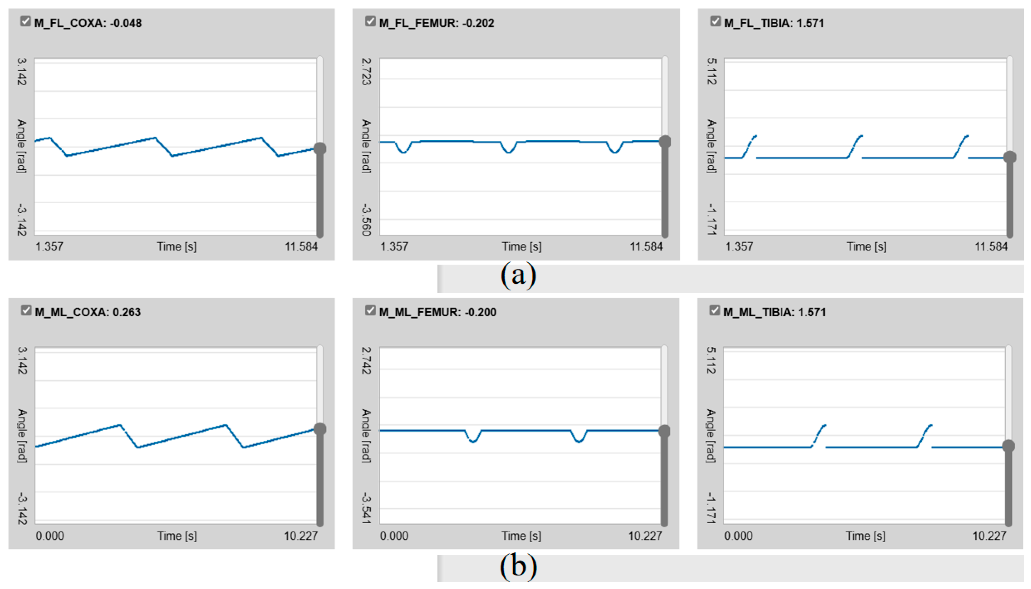
From the thigh and knee joints in the figure, it can be seen that the thigh joints are divided into six groups, with each leg moving independently, corresponding to the planned groupings mentioned above.
As shown in Figure 23, the rotation angle of the hip joint is observed. Since the rotation directions are opposite of the hip joints on the left and right sides, when one leg is lifted, the hip joint of that leg rotates forward, and the leg in the holding group rotates backward. Since only one leg is lifted each time, it rotates in the same direction for the joint of the lifted leg and the joint of the other leg, and there will be four joints with the same rotation direction at the same time. For the thigh and knee joints, each joint lifting the leg is in the same direction.
According to the simulation analysis of the above three gaits, it can be clearly seen that the gait of the hexapod robot wheel–leg conversion device designed in this study is completely consistent with the planned gait, which fully demonstrates the scientific and reliable nature of this design. At the same time, the setting of the wheel–leg conversion device greatly improves the adaptability, flexibility, and operational efficiency of the hexapod robot in different road conditions, and it would effectively enhance the functionality of the bionic hexapod robot.

4.5. Model of the Wheel-Legged Bionic Hexapod Robot

The wheel-legged hexapod bionic robot is made using 3D printing, as shown in Figure 24.

4.6. Data Acquisition and Processing

In order to verify the lightweight effect and responsiveness of the hollow robot, the hollow robot has been compared specifically with a solid 3D-printed one. The conditions are as follows: on a flat surface and walking on legs, with the same energy consumption and step size.
Firstly, the hexapod robot model is placed on a pre-set relatively flat surface, and then the robot is permitted to move according to the programmed motion pattern. At the same time, the tester captures images of the robot by using a camera at different poses during the start, movement, and stopping phases. The images are then transmitted to the software pre-installed on the computer, which can collect dynamic data on the robot in different positions and orientations. Finally, the data is stored and transferred to Matlab for analysis.
The result shows that the speed of the solid hexapod robot is 358 mm/min. After hollowing out and lightweighting, the robot can reach 1102 mm/min. The operational efficiency is more than three times that of physical robots. In terms of actual response time, after hollowing out and lightweighting, it takes about 0.2 s, while physical robots require at least 0.5 s. The wheel-legged conversion time of the solid hexapod robot is about 0.8 s; the hollowed robot can reach about 0.5 s. In terms of weight, the weight of the hollowed robot is approximately 0.5 times that of a physical solid robot.

4.7. Dynamic Analysis of Hexapod Bionic Robot with Wheel-Legged Transition Mechanism

4.7.1. Collection of Dynamic Data

As shown in Table 5, a complete process of starting, moving, and stopping is selected, and the joint angles are collected for each time step by defining a sequence of angles.

4.7.2. Change in Joint Angle

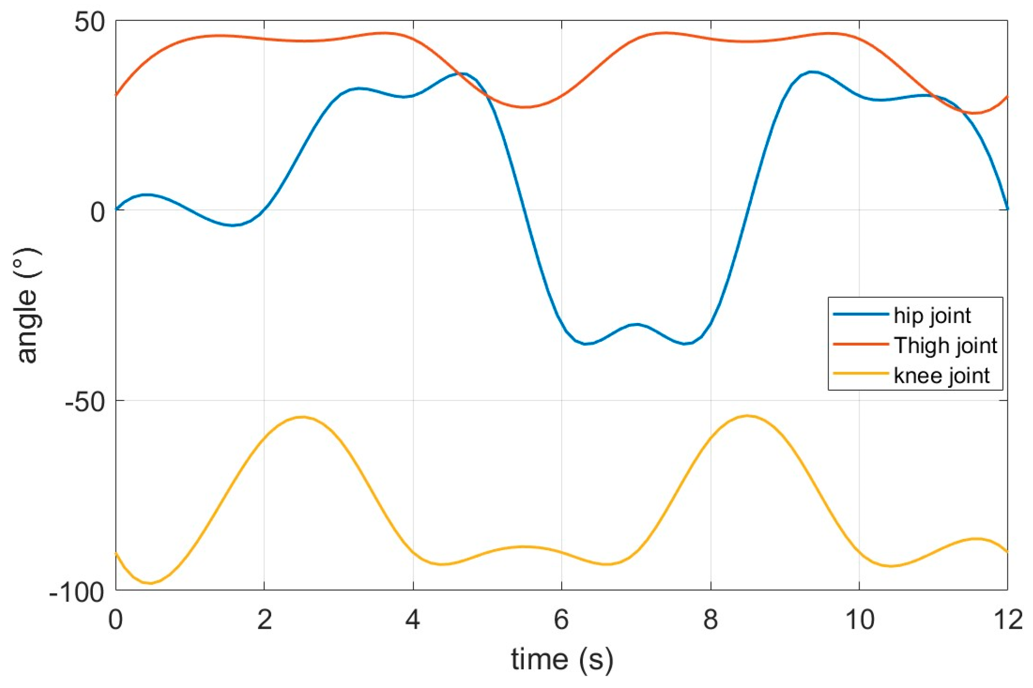
As shown in Figure 25, the hip joint undergoes reverse motion simulation walking at 6 s and 9 s, with the thigh joint rotating periodically from 30° to 45°, while the knee joint rotates synchronously from −90° to −60°, strongly verifying the effectiveness of interpolation and the periodic characteristics of motion planning.

4.7.3. Phase Diagram of Joint

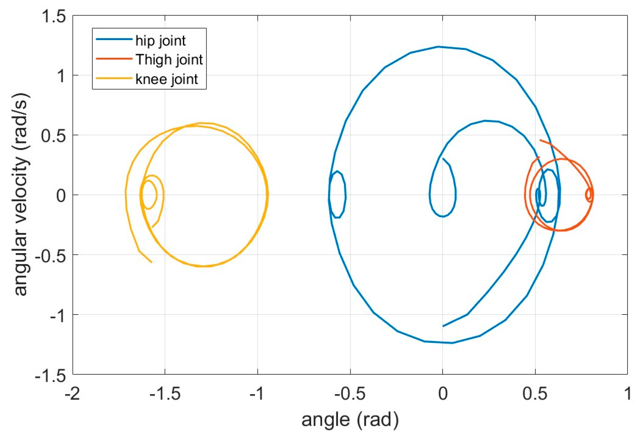
By analyzing the motion characteristics through the relationship between angle and speed, the periodic behavior of the hip joint is indicated by the closed circular trajectory. An approximate linear relationship is exhibited by both the hip joint and knee joint, indicating a positive correlation between speed and angle, as shown in Figure 26.

4.7.4. Analysis of Speed and Acceleration

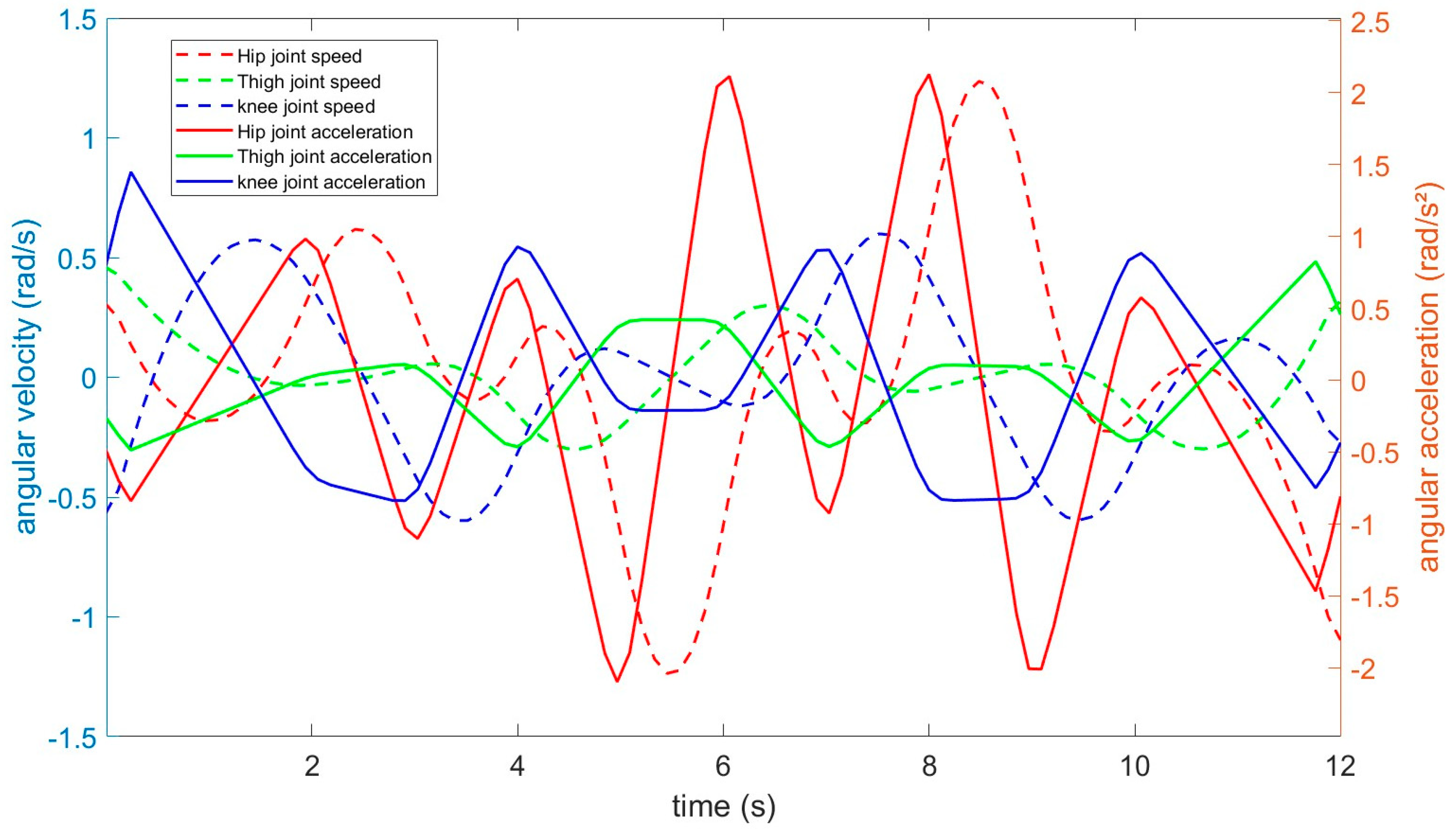
As can be seen from Figure 27, speed is represented by the dashed line, while acceleration is represented by the solid line. It has been shown by the comparison of the two different lines that the peak acceleration is evident at the start and stop moments (such as 0 s and 6 s). At the same time, the thigh joint is in a state of minimal fluctuation.

4.7.5. Analysis of Power and Energy Consumption

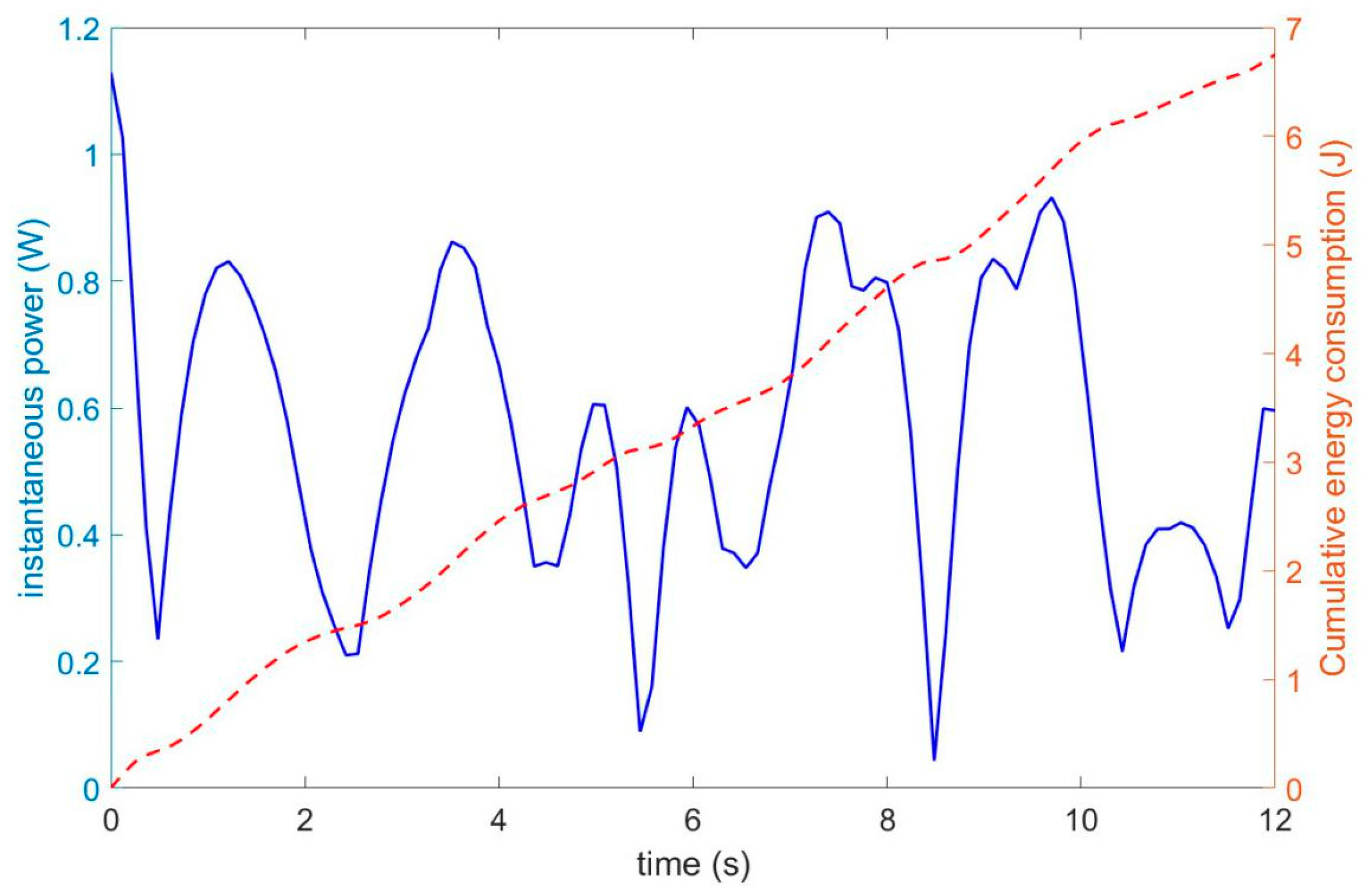
As shown in Figure 28, the high-acceleration period corresponds to the peak power, during which energy consumption increases significantly. Meanwhile, a monotonic increase is revealed over time by an analysis of the total energy consumption, with no energy recovery observed.

4.7.6. Workspace Analysis

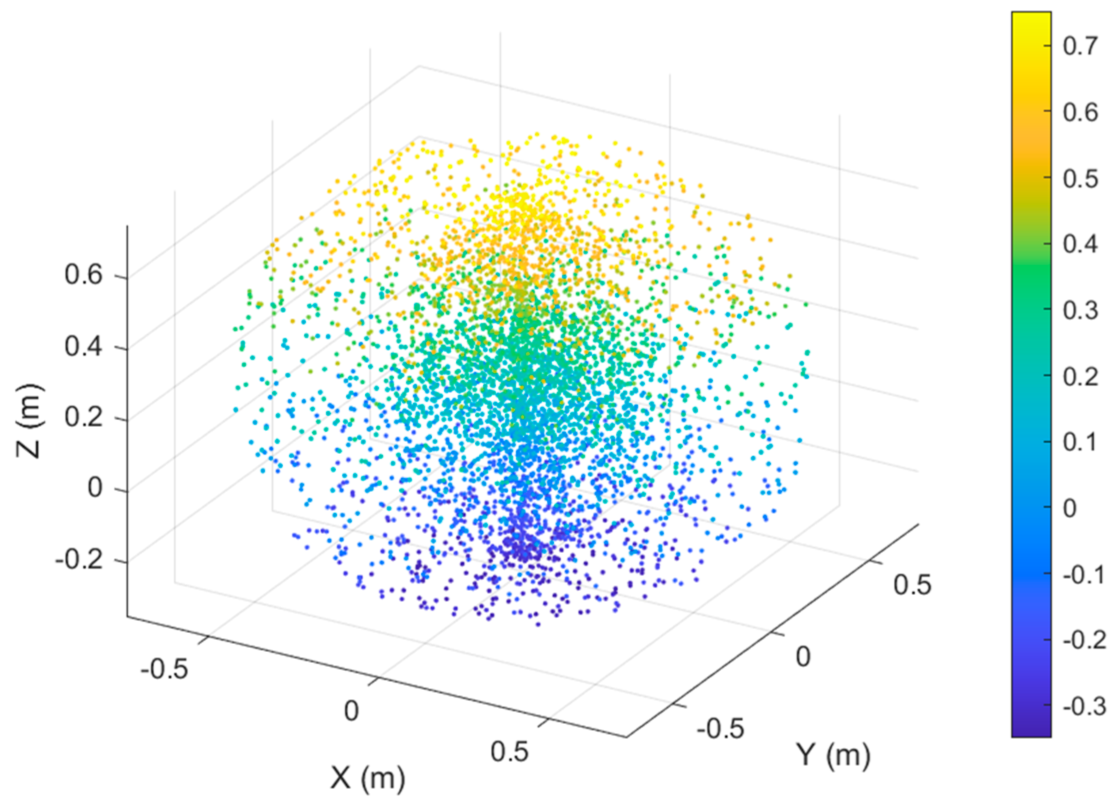
As shown in Figure 29, the Monte Carlo sampling points are distributed in a fan shape, with a wide range along the Z-axis, representing a hip joint angle of 90°. The horizontal coverage is determined by the length of each segment of the robotic arm, providing a reference for reachability in motion planning.

5. Discussion

The crank–rod transformation mechanism investigated by P. Latour, S. Chaudhary, and S. Mohan [21] enables a seamless transition between wheeled and legged locomotion via geometric reconfiguration of the linkage. By utilizing crank rotation to drive the periodic motion of the connecting rod, this system preserves the efficiency of wheeled travel while providing legged gait capabilities for obstacle negotiation. A crank–slider–linkage composite mechanism serves as the core actuation unit, where motor-driven crank rotation alternately facilitates continuous wheel rolling or discrete leg swinging. This mode switching is accomplished solely by modulating motor speed, eliminating the need for auxiliary mechanical components. Experimental results demonstrate that the robot attains a cruising speed of 5.2 m/s on flat terrain in its wheeled mode and accomplishes a transition to its legged mode to surmount 15 cm high obstacles within 0.8 s. Compared to solely wheeled or legged platforms, this crank-based mechanism achieves notable energy efficiency improvements, with experimental data indicating an approximately 30% reduction in energy consumption under equivalent task profiles.
In comparison with the aforementioned mechanism, the transformation system developed in this study exhibits several distinctive advantages:
(1)
Transition Speed: the hollow-structured robot presented here achieves a wheel–leg transition time of 0.5 s, outperforming the four-bar linkage mechanism (0.8 s) by 37.5%. This signifies a substantial improvement in transformation agility.
(2)
Energy Efficiency: the iris-based transformation mechanism operates with minimal body fluctuation, leading to lower energy expenditure while ensuring motion stability and reliability. It completely avoids the dead-center issues inherent to four-bar linkages, which typically require counterweights to overcome, thereby further increasing energy demand. The robot in this study was fabricated as a 3D-printed model using ABS plastic, resulting in a significantly lighter structure compared to the referenced four-bar linkage robot. This weight reduction contributes directly to a substantial decrease in energy consumption. Experimental results confirm that our design achieves a reduction of over 50% in energy consumption while performing the same tasks as its counterpart.
(3)
Motion Stability: in its wheeled configuration, the robot maintains a low center of gravity, ensuring high stability during traversal. In its legged mode, the leg dimensions substantially exceed those of the central body, increasing the ground contact area and effectively enhancing terrain adaptability. This addresses the limitation of excessive structural rigidity that often constrains conventional robots in uneven environments. Furthermore, the hexapod bionic configuration inherently strengthens adaptability to varied terrains, providing fundamental guarantees for operational stability and reliability.
This comparative analysis underscores the performance superiority of our iris-based transformation mechanism in terms of transition speed, energy economy, and motion stability, highlighting its potential for applications requiring efficient and adaptive multimodal locomotion.

6. Conclusions

In this study, guided by bionic principles, the hexapod structure of the robot was designed with a three-degree-of-freedom leg mechanism that closely mimics the body proportions of insects. A hollow configuration was adopted for the overall structure, achieving a lightweight design in the wheel–leg transition device, thereby significantly improving the movement speed and agility of the hexapod robot. The following conclusions can be drawn from the analysis:
The wheels of the transformation mechanism were reconfigured into an omni-directional mobility platform driven by a micro-motor. This modification, combined with the bionic hexapod architecture modeled on insect locomotion traits, further enhanced the robot’s motion flexibility. A novel design scheme based on an iris–linkage composite mechanism was proposed. This configuration ensures smooth, stable, and precise operation during the wheel–leg transition process.
In addition, through systematic gait planning and simulation, it was verified that the proposed wheel–leg transformation mechanism enables the robot to adapt to various complex terrains and improves operational efficiency by leveraging optimized wheeled and legged gait strategies.
Finally, the dynamic analysis conducted from the perspective of kinetic parameters strongly corroborates the correctness and accuracy of the proposed design for the hexapod bionic robot equipped with the wheel–leg transition mechanism. In summary, comparative evaluations demonstrate that the hollow lightweight hexapod robot not only surpasses its solid counterpart in terms of weight reduction and response sensitivity, but also significantly exceeds it in operational efficiency and movement speed. It can be concluded that the development and implementation of the wheel–leg transformation mechanism will provide substantial practical and guiding significance for future research in hexapod bionic robotics.

Author Contributions

Y.M. conceived and designed the study, collected and analyzed the data, and wrote the manuscript. S.W. provided guidance and supervision throughout the study, and critically revised the manuscript. A.G. and P.Q. focused on the data analysis and interpretation, and critically revised the manuscript. W.H., Q.Y., H.L. and C.L. contributed to design and printed the hexapod bionic robot. All authors have read and agreed to the published version of the manuscript.

Funding

This research was funded by the Natural Science Foundation of Shandong Province, grant number ZR2023ME154.

Data Availability Statement

Data will be made available on request.

Conflicts of Interest

The authors hereby confirm that no conflicts of interest exist for this article.

References

  1. De Viragh, Y.; Bjelonic, M.; Bellicoso, C.D.; Jenelten, F.; Hutter, M. Trajectory Optimization for Wheeled-Legged Quadrupedal Robots Using Linearized ZMP Constraints. IEEE Robot. Autom. Lett. 2019, 4, 1633–1640. [Google Scholar] [CrossRef]
  2. Nakajima, S. RT-Mover: A Rough Terrain Mobile Robot with a Simple Leg-Wheel Hybrid Mechanism. Int. J. Rob. Res. 2011, 30, 1609–1626. [Google Scholar] [CrossRef]
  3. Peng, P.; Zhang, X.J.; Yuan, G.M.; Liu, Z. Dynamic Analysis of the Wheel-Legged Mobile Robot. Appl. Mech. Mater. 2013, 344, 174–181. [Google Scholar] [CrossRef]
  4. Chen, W.-H.; Lin, H.-S.; Lin, Y.-M.; Lin, P.-C. TurboQuad: A Novel Leg–Wheel Transformable Robot with Smooth and Fast Behavioral Transitions. IEEE Trans. Robot. 2017, 33, 1025–1040. [Google Scholar] [CrossRef]
  5. Zhou, F.; Xu, X.; Xu, H.; Zou, T.; Zhang, L. Transition Mechanism Design of a Hybrid Wheel-Track-Leg Based on Foldable Rims. Proc. Inst. Mech. Eng. Part C J. Mech. Eng. Sci. 2019, 233, 4788–4801. [Google Scholar] [CrossRef]
  6. Wei, C.; Yao, Y.; Wu, J.; Liu, R. Development and Analysis of a Closed-Chain Wheel-Leg Mobile Platform. Chin. J. Mech. Eng. 2020, 33, 80. [Google Scholar] [CrossRef]
  7. Wang, T.-H.; Lin, P.-C. A Reduced-Order-Model-Based Motion Selection Strategy in a Leg-Wheel Transformable Robot. IEEE/ASME Trans. Mechatron. 2022, 27, 3315–3321. [Google Scholar] [CrossRef]
  8. Bledt, G.; Powell, M.J.; Katz, B.; Di Carlo, J.; Wensing, P.M.; Kim, S. MIT Cheetah 3: Design and Control of a Robust, Dynamic Quadruped Robot. In Proceedings of the 2018 IEEE/RSJ International Conference on Intelligent Robots and Systems (IROS), Madrid, Spain, 1–5 October 2018; IEEE: Piscataway, NJ, USA, 2018; pp. 2245–2252. [Google Scholar] [CrossRef]
  9. Zhang, M.; Su, Y. Research on Obstacle Performance and Tipping Stability of a Novel Wheel–Leg Deformation Mechanism. Mech. Sci. 2023, 14, 1–13. [Google Scholar] [CrossRef]
  10. Chen, H.-Y.; Wang, T.-H.; Ho, K.-C.; Ko, C.-Y.; Lin, P.-C.; Lin, P.-C. Development of a Novel Leg-Wheel Module with Fast Transformation and Leaping Capability. Mech. Mach. Theory 2021, 163, 104348. [Google Scholar] [CrossRef]
  11. Li, H.; Xie, Z.; Cao, Y.; Zhang, R.; Qin, J. Design and Analysis of a Mobile Robot with Transformable Wheel-Legged Mechanism. J. Mech. Robot. 2025, 17, 061015. [Google Scholar] [CrossRef]
  12. Cao, J.; Zhang, J.; Wang, T.; Meng, J.; Li, S.; Li, M. Mechanism Design and Dynamic Switching Modal Control of the Wheel-Legged Separation Quadruped Robot. Robotica 2023, 42, 660–683. [Google Scholar] [CrossRef]
  13. Zhang, R.; Pang, H.; Ji, Q.; Li, G.; Dong, W.; Wen, L.; Li, J. Structure Design and Traction Trafficability Analysis of Multi-Posture Wheel-Legs Bionic Walking Wheels for Sand Terrain. J. Terramechanics 2020, 91, 31–43. [Google Scholar] [CrossRef]
  14. Pan, K.; Zhang, Q.; Wang, Z.; Wang, S.; Zhou, A.; You, Y.; Wang, D. Method for the Posture Control of Bionic Mechanical Wheel-Legged Vehicles in Hilly and Mountainous Areas. Int. J. Agric. Biol. Eng. 2024, 17, 151–162. [Google Scholar] [CrossRef]
  15. Felton, S.M.; Tolley, M.T.; Onal, C.D.; Rus, D.; Wood, R.J. Robot Self-Assembly by Folding: A Printed Inchworm Robot. In Proceedings of the 2013 IEEE International Conference on Robotics and Automation, Karlsruhe, Germany, 6–10 May 2013; IEEE: Piscataway, NJ, USA, 2018; pp. 277–282. [Google Scholar] [CrossRef]
  16. Xu, K.; Wang, S.; Shi, L.; Li, J.; Yue, B. Horizon-Stability Control for Wheel-Legged Robot Driving over Unknow, Rough Terrain. Mech. Mach. Theory 2025, 205, 105887. [Google Scholar] [CrossRef]
  17. Mostyn, V.; Krys, V.; Kot, T.; Bobovsky, Z.; Novak, P. The Synthesis of a Segmented Stair-Climbing Wheel. Int. J. Adv. Robot. Syst. 2018, 15, 1–11. [Google Scholar] [CrossRef]
  18. Pan, Z.; Liu, S.; Zhou, S.; Li, B.; Niu, Z.; Wang, R. Collaborative Control of the Knee-Wheeled Wheel-Legged Robot: Considering Actuators Characteristics. Proc. Inst. Mech. Eng. Part I J. Syst. Control. Eng. 2024, 239, 272–289. [Google Scholar] [CrossRef]
  19. Wang, D.; Fang, B.; Zheng, J. Design and Research of Deformable Wheel-Legged Robot Based on Origami Mechanisms. Proc. Inst. Mech. Eng. Part C J. Mech. Eng. Sci. 2024, 238, 8769–8784. [Google Scholar] [CrossRef]
  20. Li, Y.; Gao, J.; Chen, K.; Chen, W.; Yin, Z. Safe Trajectory Generation for Wheel-Leg Hybrid Mechanism Using Discrete Mechanics and Optimal Control. J. Mech. Robot. 2024, 16, 061014. [Google Scholar] [CrossRef]
  21. Raturi, P.; Chaudhary, S.; Mohan, S. Investigation of the Dynamic Behavior of a Slider Crank Mechanism-Based Wheel-Legged Mobile Robot. Robotica 2025, 43, 2803–2832. [Google Scholar] [CrossRef]
  22. Park, I.; Yoon, H.; Kim, S.; Kim, H.S.; Seo, T. Review on Transformable Wheel: Mechanism Classification and Analysis According to Mechanical Complexity. Int. J. Precis. Eng. Manuf. 2025, 26, 737–755. [Google Scholar] [CrossRef]
  23. Zhao, D.; Liu, J.; Yang, P.; Cui, T.; Wu, D.; Zhang, L. Modeling and Stability Control of Steering and Reconfiguration Motion for Wheel-Legged Metamorphic Robot. Proc. Inst. Mech. Eng. Part C J. Mech. Eng. Sci. 2025, 239, 4256–4272. [Google Scholar] [CrossRef]
  24. Du, Y.; Ruan, Q.; Yao, Y. Integrated Wheel–Foot–Arm Design of a Mobile Platform with Linkage Mechanisms. J. Mech. Robot. 2024, 16, 081017. [Google Scholar] [CrossRef]
  25. Kim, Y.; Kim, H.S.; Seo, T. Type Synthesis and Kinematic Analysis of a 2-DOF Shape-Morphing Wheel Mechanism for Step-Overcoming. IEEE Access 2021, 9, 86500–86513. [Google Scholar] [CrossRef]
  26. Comin, F.J.; Saaj, C.M. Models for Slip Estimation and Soft Terrain Characterization with Multilegged Wheel–Legs. IEEE Trans. Robot. 2017, 33, 1438–1452. [Google Scholar] [CrossRef]
  27. Li, J.; Liu, Y.; Yu, Z.; Guan, Y.; Zhao, Y.; Zhuang, Z.; Sun, T. Design, Analysis, and Experiment of a Wheel-Legged Mobile Robot. Appl. Sci. 2023, 13, 9936. [Google Scholar] [CrossRef]
  28. Qiao, G.; Song, G.; Zhang, Y.; Zhang, J.; Li, Z. A Wheel-Legged Robot with Active Waist Joint: Design, Analysis, and Experimental Results. J. Intell. Robot Syst. 2016, 83, 485–502. [Google Scholar] [CrossRef]
  29. Won, J.; Ryu, S.; Kim, S.; Yoo, K.Y.; Kim, H.S.; Seo, T. Design Optimization of a Linkage-Based 2-DOF Wheel Mechanism for Stable Step Climbing. Sci. Rep. 2022, 12, 16912. [Google Scholar] [CrossRef]
  30. Shin, J.; Son, D.; Kim, Y.; Seo, T. Design Exploration and Comparative Analysis of Tail Shape of Tri-Wheel-Based Stair-Climbing Robotic Platform. Sci. Rep. 2022, 12, 19488. [Google Scholar] [CrossRef]
  31. Zhai, Z.; Wang, S.; Yang, G.; Guo, A.; Qu, P.; Song, Y.; Shao, S.; Zang, J. Novel Sandwich Structures with Double-Row and Crossed Pyramidal Lattice Cores: Design, Fabrication and Bending Behavior. Eng. Fail. Anal. 2025, 170, 109267. [Google Scholar] [CrossRef]
  32. Su, X.; Wang, S.; Guo, A.; Qu, P.; Guo, S.; Yang, G.; Yin, L.; Guo, M. Coupled Structure of Double-Layer Conical Shells and Annular Plates: Design, Fabrication and Compressive Property. Mater. Today Commun. 2025, 47, 113128. [Google Scholar] [CrossRef]
  33. Cornejo, J.; Weitzenfeld, A.; Baca, J.; Gecilia, E. Aerospace Bionic Robotics: BEAM-D Technical Standard of Biomimetic Engineering Design Methodology Applied to Mechatronics Systems. Biomimetics 2025, 10, 668. [Google Scholar] [CrossRef]
  34. Wang, S.; Yang, G.; Song, Y.; Shao, S.; Huang, S.; Zhang, J. Vibration characteristics of composite spherical shell with different numbers of damping cores. Alex. Eng. J. 2025, 120, 598–613. [Google Scholar] [CrossRef]
  35. Zhai, Z.; Wang, S.; Li, S.; Guo, A.; Qu, P.; Song, Y.; Yang, G.; Shao, S.; Tang, R. An experimental and numerical investigation into compressive failure of pyramidal lattice sandwich structures fabricated using stereolithography technology. Fatigue Fract. Eng. Mater. Struct. 2024, 47, 2823–2840. [Google Scholar] [CrossRef]
  36. Wang, S.; Song, Y.; Qiao, Y.; Shao, S.; Wang, W. Dynamic performance of functionally graded composite structures with viscoelastic polymers. Sci. Rep. 2024, 14, 7613. [Google Scholar] [CrossRef] [PubMed]
Figure 1. Schematic diagram of insect.
Processes 13 03364 g001
Figure 2. Schematic diagram of bionic hexapod structure. 1—torso structure; 2—three-degree-of-freedom leg structure.
Processes 13 03364 g002
Figure 3. Schematic diagram of three-degree-of-freedom leg structure. 1—base joint fixture; 2—thigh joint fixture; 3—shin joint fixture.
Processes 13 03364 g003
Figure 4. D-H coordinate system of the three-axis robotic arm.
Processes 13 03364 g004
Figure 5. Results of leg’s static analysis. (a) The maximum yield force of tibia joint; (b) The maximum yield force of coxa joint; (c) The maximum displacement of tibia joint; (d) The maximum displacement of coxa joint; (e) The maximum strain of tibia joint; (f) The maximum strain of coxa joint.
Processes 13 03364 g005
Figure 6. Schematic diagram of wheel structure. 1—first outer wheel hub; 2—motor; 3—inner wheel hub; 4—small roller; 5—second outer wheel hub.
Processes 13 03364 g006
Figure 7. Schematic diagram of diagonal motion.
Processes 13 03364 g007
Figure 8. Schematic diagram of rotational mode.
Processes 13 03364 g008
Figure 9. Schematic diagram of wheel-legged conversion mechanism. 1—distance-limiting plate; 2—steering engine; 3—position-limiting plate; 4—pushing rod; 5—retracting–extending rods for the wheel; 6—connecting rods of the wheel.
Processes 13 03364 g009
Figure 10. Schematic diagram of wheel-legged conversion mechanism. (a) Diameter of the circle where the protruding cylinder on the push rod terminates; (b) Diameter of the circle where the starting position of the protruding cylinder on the push rod is located. (c) The distance has been traveled by the push rod.
Processes 13 03364 g010
Figure 11. Schematic diagram of the state of the linkage mechanism.
Processes 13 03364 g011
Figure 12. Schematic diagram of simulation scene.
Processes 13 03364 g012
Figure 13. The whole shape of the bionic hexapod robot.
Processes 13 03364 g013
Figure 14. Schematic diagram of triangular gait of bionic hexapod robot. (a) leg lift; (b) step forward; (c) Leg on the ground.
Processes 13 03364 g014
Figure 15. Schematic diagram for ripple gait of bionic hexapod robot. (a) leg lift; (b) step forward 1; (c) step forward 2; (d) Leg on the ground.
Processes 13 03364 g015
Figure 16. Schematic diagram of the wave gait of bionic hexapod robot. (a) Leg A is Lifted off the ground and swung forward; (b) Leg B is Lifted off the ground and swung forward; (c) Leg C is Lifted off the ground and swung forward; (d) Leg D is Lifted off the ground and swung forward; (e) Leg E is Lifted off the ground and swung forward; (f) Leg F is Lifted off the ground and swung forward; (g) A complete gait cycle has been accomplished.
Processes 13 03364 g016
Figure 17. Simulation flowchart based on Webots.
Processes 13 03364 g017
Figure 18. Schematic diagram of triangle gait simulation. (a) The original state; (b) The state of triangular gait.
Processes 13 03364 g018
Figure 19. Waveform diagram of rotation angles of each joint in triangular gait. (a) Waveform diagram of left anterior joint position sensor; (b) Waveform diagram of left middle joint position sensor.
Processes 13 03364 g019
Figure 20. Schematic diagram of ripple gait simulation. (a) The original state; (b) The state of ripple gait.
Processes 13 03364 g020
Figure 21. Diagram of joint rotation angles in ripple gait waveform. (a) Waveform diagram of left anterior joint position sensor; (b) Waveform diagram of left middle joint position sensor.
Processes 13 03364 g021
Figure 22. Schematic diagram of wave gait simulation. (a) The original state; (b) The state of fluctuating gait.
Processes 13 03364 g022
Figure 23. Waveform diagram of rotation angles of each joint in wave gait. (a) Waveform diagram of left anterior joint position sensor; (b) Waveform diagram of left middle joint position sensor.
Processes 13 03364 g023
Figure 24. Model of the wheel-legged bionic hexapod robot.
Processes 13 03364 g024
Figure 25. Diagram of joint angle changes.
Processes 13 03364 g025
Figure 26. Diagram of joint phase changes.
Processes 13 03364 g026
Figure 27. Analysis diagram of speed and acceleration.
Processes 13 03364 g027
Figure 28. Analysis diagram of power and energy consumption.
Processes 13 03364 g028
Figure 29. Analysis diagram of workspace.
Processes 13 03364 g029
Table 1. D-H parameter table of the three-axis robotic arm.
iθi/raddi/mmai/mmαi/rad
1π/2020π/2
2π/60250
3−π/20350
Table 2. Information on grid.
ItemCoxa ParametersTibia Parameters
Type of gridsolidsolid
The used gridstandardstandard
Jacobian points with high quality grid16 points16 points
Size of cell0.981292 mm0.965056 mm
Tolerance0.0490646 mm0.0482528 mm
Quality of grid excellentexcellent
Number of nodes105,665104,227
Number of cells65,24362,863
Maximum aspect ratio7.96137.0838
Table 3. Parameter table for analysis of diagonal motion patterns.
DirectionM1M2M3M4
left front0+0
left rear00+
right front+00
right rear0+0
Table 4. Table of settings of physical parameters for simulation scene.
ItemValueFunction
Gravitational acceleration9.81 m/s2Simulation of a real gravity environment
Coefficient of ground elasticity0.2Preventing reboundence from the end of the foot
Air density1.29 kg/m3Affecting wind resistance during high-speed motion
Step size30 mmMaximum distance of a single leg in a single movement
Speed900 mm/minMovement speed of hexapod robot
Table 5. Sequence table of collected angle data on each joint.
Time StepHip JointThigh JointKnee Joint
00pi/6−pi/2
10pi/4−pi/2
20pi/4−pi/3
3pi/6pi/4−pi/3
4pi/6pi/4−pi/2
5pi/6pi/6−pi/2
6−pi/6pi/6−pi/2
7−pi/6pi/4−pi/2
8−pi/6pi/4−pi/3
9pi/6pi/4−pi/3
10pi/6pi/4−pi/2
11pi/6pi/6−pi/2
120pi/6−pi/2
Disclaimer/Publisher’s Note: The statements, opinions and data contained in all publications are solely those of the individual author(s) and contributor(s) and not of MDPI and/or the editor(s). MDPI and/or the editor(s) disclaim responsibility for any injury to people or property resulting from any ideas, methods, instructions or products referred to in the content.