Abstract
During narrow coal pillar mining, a high-temperature point can easily form inside the coal pillar, leading to CSC. This study aims to investigate the effect of key layout parameters of a bending heat pipe on the heat transfer from a coal pillar oxidation heat source. The bending heat pipe (Tianjin Xinhua Energy Equipment Technology Co., Ltd., Tianjin, China) heat transfer model was constructed using the Fluent software 2021 R1; meanwhile, the effects of heat transfer of non-uniform and uniform temperature fields under different spacings (30 cm, 40 cm, 50 cm) of a single heat pipe and multiple heat pipes were studied. According to our findings, the maximum temperature error between the simulated and experimental temperature fields in the bent heat pipe under identical operating conditions is 3.8 °C, which verifies the model’s feasibility. The temperature field in each section of the coal pillar exhibits a “wave-like” change trend in the heat pipe, with the heat transfer effect diminishing markedly as the spacing increases. Considering the thermal effect and on-site operation feasibility, the optimal spacing of the two bending heat pipes is determined to be 30–40 cm. These research results can offer a theoretical foundation for the application of bending heat pipes in the advanced prevention of the hidden danger of CSC in narrow coal pillar mining.
1. Introduction
To effectively improve the recovery efficiency of coal, narrow coal pillar mining technology has become the main method for mining medium-thick coal seams [1,2,3]. The coal pillar is a coal–rock mass with a pressure relief hole fracture. Affected by the mining depth and mine pressure, it will form a coal pillar fracture zone in the shallow part and around the closed wall, resulting in serious air leakage and oxygen supply in this area, inducing spontaneous combustion and oxidation inside the coal body and generating high-temperature points, causing spontaneous combustion in local coal pillars. It not only greatly threatens the safety of the working face but also results in coal resource waste. Therefore, it is particularly critical to solve the problem of spontaneous combustion of broken coal pillars in the goaf of a working face.
The fire resulting from spontaneous combustion due to coal pillar oxidation is more complicated than spontaneous combustion of coal within the goaf [4,5]. Research shows that the environment of underground roadways in a coal mine is relatively closed, and ventilation is limited. In addition, the coal pillar can easily become the core area of spontaneous combustion accidents because of coal’s tendency to spontaneously combust [6]. Due to the instability of the air flow and the formation of a local vortex, the oxygen supply in some areas of the coal pillar will be higher, resulting in heat accumulating to form a “high-temperature point” for spontaneous combustion. At present, the method for dealing with spontaneous combustion of a coal pillar is mainly through temperature monitoring and high-temperature point detection, combined with the techniques of grouting and nitrogen injection for fire extinguishing [7,8]. However, due to the concealment of high-temperature ignition sources, this method of monitoring first and extinguishing later often cannot deal with the high-temperature point in a coal pillar in time, which leads to a higher rate of coal spontaneous combustion (CSC). A gravity heat pipe serves as a high-efficiency heat transfer system through the natural convection and circulation mechanism of liquid–vapor conversion. It is the device that achieves the best heat transfer performance in passive cooling technology [9]. Heat pipe technology is extensively used in engineering fields like electronic device cooling, geothermal energy extraction, aerospace, and nuclear reactors due to its good heat transfer performance and cost-effectiveness [10,11,12,13,14,15,16]. On this basis, researchers have further explored its application in environments where heat accumulates easily, such as coal piles, coal gangues, and rice husk piles, analyzing its efficiency in these scenarios [17,18,19]. De León-Ruiz et al. [20] studied the effect of different aspect ratios on the heat transfer performance of a gravity heat pipe. Combined with the model construction, they found that increasing the aspect ratio can improve the heat transfer efficiency of the heat pipe, and when the aspect ratio is ≥100, the evaporation performance of the heat pipe is optimal. It can therefore be seen that increasing the aspect ratio is beneficial to the heat transfer and cooling of high-temperature points in a coal pillar. Dai et al. [21] expounded the advantages of heat pipe technology by combining the advantages and disadvantages of spontaneous coal combustion mechanisms and traditional prevention and control methods and summarized and analyzed the working medium, arrangement mode, heat pipe structure, external environment, and other factors affecting the heat transfer efficiency of a gravity heat pipe. To solve the problems of resistance and energy loss of finned heat pipes due to return air flow in mines, Zhai et al. [22] improved the original finned heat pipe design to a gravity heat pipe with an elliptical smooth surface. Their results show that the specific enthalpy is improved by appropriately changing the ellipticity of the tube bundle, thereby reducing the generation of entropy. When the ellipticity is 0.61, the specific enthalpy increases by 19.28%, and the cooling effect is optimal. To improve heat pipes’ heat dissipation efficiency, Xie et al. [23] prepared a heat pipe based on the chimney effect. Their results show that the distance between the chimney and ground, the length of the chimney expansion section, the chimney’s inlet radius, the distance between the heat pipe and inner wall of the chimney, and the chimney height all significantly affect a heat pipe’s heat dissipation efficiency. Parameters of a chimney heat pipe were optimized using the response surface analysis method, and the optimized heat pipe achieved a 3-fold increase in heat dissipation efficiency.
Tong et al. [24] explored heat transfer process parameters for heat pipes and discussed how these affected the coal gangue pile’s temperature field. Their results show that that a better cooling effect could be achieved after decreasing the heat pipe’s insertion distance while increasing the insertion depth, with the best effect being achieved at a 3 m insertion distance and 7 m insertion depth. Based on these findings, compared with the insertion depth, the heat pipe’s insertion distance affected the temperature field of a coal gangue pile more clearly. Kumar et al. [25] carried out a comparative study concerning several groups of symmetrical insertion angles in heat pipe layout parameters. The heat transfer effect of the symmetrical angle of the inclination angle shows basically the same characteristics. Under these symmetrical inclination angles, the working fluid circulation and heat transfer mechanism inside the heat pipe are similar, with insignificant differences in heat transfer performance. Xiao et al. [26] conducted in-depth research on the proportion of a two-phase closed thermosyphon and its cooling rate at different insertion angles in bituminous coal piles. When the two-phase closed thermosyphon is added in a coal pile at a 60° inclination angle, the best heat transfer effect is achieved. To solve the problem of spontaneous combustion in coal gangue dumps, Zhang et al. [18] proposed an efficient heat conduction and waste heat recovery system based on heat pipes. They discovered that the heat pipe had the highest cooling effect and heat recovery efficiency when a water–ethylene glycol mixture with a filling rate of 60% was utilized as the working medium at an aspect ratio of 80, when a 7.64% peak power generation efficiency was achieved. Wei et al. [27] studied a heat pipe’s heat transfer effect under diverse experimental conditions. They found that after heating the coal pile from 100 °C to 150 °C, a heat pipe insertion ratio of 4:1 is obtained, and the air flow rate is 2.0 m/s, with the heat transfer efficiency increasing by 79% and 93%, respectively. This finding provides important guidance for optimizing the layout of heat pipes and their application in coal piles.
In summary, both domestic and international scholars have carried out research on the application of heat pipes in the fields of coal gangue and coal pile heat dissipation. However, the research on the early prevention and control of oxidation and temperature increases in a broken coal pillar area is not comprehensive. In the face of the dangerous occurrence of CSC in a roadway under the action of high mine pressure, the questions of how to effectively apply a bending heat pipe and optimize its layout parameters, as well as how to analyze the working state variation law in different temperature areas, are lacking corresponding theoretical guidance. Therefore, this paper focuses on the problem of advanced prevention and control of CSC fires induced by oxidation and high-temperature points within a broken area in roadway coal pillars. The Fluent simulation software (2021 R1) was used to study the heat transfer effect of an individual bending heat pipe on the heat source of the coal body, as well as the influence of the bending heat pipe on the heat transfer and cooling effect of the temperature field under different spacings. Our findings provide a theoretical basis for designing a layout for bending heat rods in areas with a risk of CSC and have important practical value for actively preventing and controlling spontaneous combustion due to oxidation within the broken area of a coal pillar.
2. Construction of Mathematical Model of Heat Transfer in Bending Heat Pipe
2.1. Analysis of Heat Transfer Principle of Bending Heat Pipe
The gravity heat pipe is composed of a sealed metal tube filled with cooling circulating refrigerant. The heat pipe consists of an endothermic section, an adiabatic section, and a condensing section. Its working principle is that the working medium is responsible for heat absorption and will evaporate first. The working medium within the tube absorbs heat to form steam and rises to the condensation section. Thereafter, the steam in the condensation section contacts this section’s wall at a lower ambient temperature. The steam cools and condenses into a liquid to release excess heat. This heat is transmitted to the external environment or the cooling medium of the condensation section. Finally, the steam is re-liquefied into a liquid working medium. Due to gravity, the liquid working medium falls back along the pipe wall to the lower endothermic section. Then, the liquid working medium is heated again and evaporates repeatedly [28]. Since the gravity heat pipe does not have a liquid-absorbing core structure, it relies solely on gravity to perform the reflux circulation of the working medium. Therefore, the heat absorption section must be placed below the condensation section to ensure the smooth reflux of the condensate.
In view of the narrow space and complex environment of a coal mine roadway, the influence of geological tectonic stress, mining activities, and other factors can easily lead to the formation of dangerous high-temperature oxidation areas of the coal pillar, which poses a serious threat to coal mine safety [29]. Traditional heat dissipation methods are often ineffective in dealing with local high-temperature problems in such a narrow space. Therefore, to efficiently decrease the heat of the early high-temperature point in a small space, a low-temperature heat pipe with a bending angle is selected (Tianjin Xinhua Energy Equipment Technology Co., Ltd., Tianjin, China). The bending structure of this heat pipe not only helps as it can be flexibly arranged in narrow spaces such as roadway coal pillars to save space but also ensures the quick starting of the heat pipe at a low temperature during early oxidation of the coal, thereby maximizing the heat pipe’s heat transfer efficiency. Due to the evaporation of the internal working medium and its condensation cycle process, a low-temperature heat pipe efficiently transfers heat from a high-temperature point to the outside of the roadway or a safety area further away for heat dissipation, which effectively inhibits the local high-temperature phenomenon caused by the oxidation reaction in the broken area of the coal pillar. A schematic diagram of the experimental heat pipe structure and its heat transfer principle is provided in Figure 1.
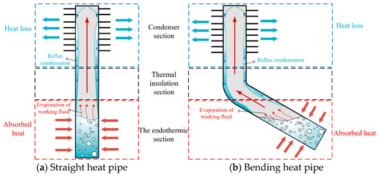
Figure 1.
Diagram showing experimental heat pipe’s structure and heat transfer principle.
2.2. Basic Assumptions of the Model
As the heat transfer process in heat pipe is complex, several assumptions are made based on the actual conditions:
- (1)
- The assumption that the surface temperature in a heat pipe module within a coal pillar is constant: It is assumed that the surface temperature of the module remains unchanged and is not affected by the fluctuation of other external factors. This assumption aims to eliminate the interference of dynamic changes in the external environment in the heat transfer process to evaluate the heat transfer characteristics of the heat pipe itself more accurately. This assumption is helpful for enhancing the analyticity of experimental data and the reliability of our model verification.
- (2)
- Radial heat transfer hypothesis: The heat conduction in the coal pillar only occurs along the radial direction, and all heat that is released can be transferred directly into the heat pipe via heat conduction, without considering other heat transfer mechanisms. This assumption is based on the actual working mechanism of the heat pipe in the coal pillar, that is, that the heat is absorbed from the inside of the coal body along the radial direction and dissipates heat to the outside. The simplified treatment can effectively reduce the dimensionality of the model, help us focus on the key role of the heat pipe in the radial heat conduction process, and improve the practicability of the model.
- (3)
- The assumption of constant thermophysical properties of loose coal: It is assumed that the thermal conductivity, density, porosity, and particle size distribution of coal remain constant during the simulation. This assumption is based on the consideration that the experimental period is short, and the thermal properties of coal do not change significantly. This treatment can simplify the structure of the control equation, so that the analysis is focused on the heat transfer efficiency of the heat pipe and avoids the interference of thermophysical parameters.
- (4)
- Ignoring the thermal resistance of the pipe wall: As a pipe wall has relatively low thermal resistance and a coal body is loose, the thermal resistance generated by the heat conduction of the pipe wall is ignored. This assumption is based on the fact that the thermal conductivity of the heat pipe is much higher than that of the surrounding coal, and its thermal resistance can be ignored in the simplified model. This simplification helps focus this study on the heat exchange process at the coal–heat pipe interface and improve the characterization ability of the model.
- (5)
- The assumption of heat insulation and heat preservation of the experimental system: We ignore any heat exchange of the experimental coal body with the external environment to ensure that the simulated thermal response is purely derived from the heat transfer effect of the heat pipe. This condition is helpful for improving the accuracy and explanatory power of numerical simulation.
2.3. Heat Transfer Control Equation of Heat Pipe
The equation for transient heat conduction energy conservation is developed based on the heat transfer control equation [30]:
where represents the coal pile density, in kg/m3; k1 is the coal pile’s thermal conductivity, in W/(m·K); c is the coal pile’s specific heat capacity, in J/(kg·K); T is the coal pile’s temperature, in K; represents the temperature component of the coal pile in each direction; t is time, in h; and stands for the coal heat removed by the heat pipe, in J.
The resistance that the heat pipe, as a heat transfer element, needs to overcome is called the thermal resistance, as in Equation (2), and is represented by the temperature-difference-to-heat-transfer ratio [31].
In the above formula, stands for the temperature difference, in K; R represents the total thermal resistance, in K/W; and q is the heat transfer steam.
Ignoring the thermal resistance Rc and Rd, which insignificantly affect the total thermal resistance, the total thermal resistance R is simplified into Equation (3) [32]:
where d0 stands for the heat pipe’s outer diameter, in m; de represents its length, in m; di stands for its inner diameter, in m; λw indicates the thermal conductivity, in W/m·K; he,i represents the convective heat transfer coefficient, in W/(m2·K); lc denotes the condensation section’s length, in m; hc,i is the heat transfer coefficient in the condensation section, in W/(m2·K); le represents the endothermic section’s length, in m; Ahp,c denotes the heat transfer area in the condensation section, in m2; is the convective heat transfer coefficient of the area of the condensation section with air, in W/(m2·K); Rc represents the thermal resistance of the gaseous working medium moving to the condensation section under pressure difference, in K/W; and Rd represents the thermal resistance of the gaseous working fluid releasing heat in the condensation section and being condensed into liquid, in K/W.
For the heat pipe, its heat transfer and cooling are equivalent to the heat transfer via the metal rod. The heat transfer performance in its heat absorption and condensation sections can reflect its heat transfer capacity during the entire heat transfer procedure. Therefore, equivalent thermal conductivity is introduced to represent its heat transfer capacity, which [33] is shown in Equation (4).
where k2 is the heat pipe wall’s thermal conductivity, in W/(m·K); l represents the heat pipe’s length, in m; le is the endothermic section’s length, in m; lc is the condensation section’s length, in m; represents the boiling heat transfer coefficient of its endothermic section, in W/(m2·K); and is the heat transfer coefficient of the condensation section, in W/(m2·K).
The heat transfer between the heat pipe’s evaporation section and the part of the coal body that is in contact with the heat pipe can be expressed as follows [31]:
where represents the coal’s heat transfer coefficient, in W/(m·K); T represents the temperature of the coal body that is in contact with the heat pipe’s heat absorption section, in K; stands for the heat pipe’s heat transfer coefficient, in W/(m·K); and represents its evaporation section’s temperature, in K.
3. Heat Transfer Model and Parameter Setting for Bending Heat Pipe
3.1. Model Construction and Grid Division
During actual field applications, a single heat pipe often cannot reach the required heat transfer level, so using multiple heat pipes to transfer heat is important; this study models and analyzes how the spacing between these affects efficiency and identifies the best heat pipe spacing. By exploring the influence of two bent heat pipes and various spacings between these on the coal pillar crushing zone’s temperature field and the heat transfer efficiency of the heat pipe itself, the optimal heat transfer spacing at the scale of an actual site is determined.
Taking the coal pillar of a mine in Huangling, Shaanxi Province, as the prototype, the 3D geometric model (length, 120 × 80 × 60 cm) was obtained by using a ratio of 1:1000. In order to simplify the calculation, the heat pipe is equivalent to a metal rod with cold source properties in the modeling process; in addition, a heat transfer model for a single bent heat pipe can be established according to the position of the experimental heat pipe. During the experiment, because the coal body is close to the wall of the coal tank in the front and rear sections, the heat is lost at the coal tank’s outer wall. Therefore, a heat transfer radius of about 20 cm in the middle section was selected as the theoretical spacing, while heat transfer models of two bending heat pipes with diverse spacings of 30 cm, 40 cm, and 50 cm were also established. Ignoring the thermal radiation of the coal body, the transient solution is solved for 24 h. The established model is meshed, and a total of 486,414 grid domain units are divided. The calculation model and grid division are shown in Figure 2.
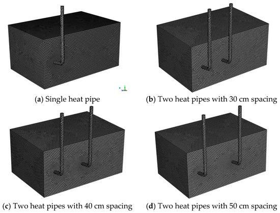
Figure 2.
Models and grids.
3.2. Initial Conditions and Parameter Settings
In order to simulate a heat transfer experiment with a bending heat pipe in a temperature field within a coal pillar fracture zone more accurately, along with the temperature distribution data for the coal body in different sections, the temperature field distribution law of a heat pipe inserted at 60 °C is fitted in the experiment. The specific expression is shown in Equation (6), while the energy equation is shown in Equation (7). The initial coal pile temperature is defined to be 60 °C by UDF. The temperature field of the coal pile’s initial state can be observed in Figure 3, and the material properties and parameter settings of the modeling are presented in Table 1.
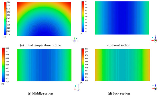
Figure 3.
Temperature field distribution of the coal pile in its initial state at 60 °C.

Table 1.
Material properties and parameter settings of model.
In the above formula, T represents the coal seam temperature when the distance from the origin is X and the height is Y, in K; X represents the distance from the coal pile’s measuring point to the origin, with a range of (0,120); Y denotes the distance from the bottom of the coal pile bottom (0,60), in cm; λ represents the thermal conductivity, in W/(m2·K); Se stands for the energy source term, in J/m3·s; e is the internal energy, in J/kg; and ρ is the density, in kg/m3.
3.3. Verification of Numerical Simulation
To quantify the heat transfer and cooling effect of a bent heat pipe and verify our model’s accuracy, a heat transfer test bench for the bent heat pipe was prepared. The experimental platform is mainly composed of an experimental coal tank (from Tianjin Xinhua Energy Equipment Technology Co., Ltd., Tianjin, China) and temperature control system. The main body of the experimental coal tank is composed of 3 mm steel plates, and its length, width, and height are 150 cm × 100 cm × 100 cm, respectively. The movable leaf opening is set above the box to fill the coal sample and temperature monitoring equipment. The rectangular drawing port is located 60 cm from the ground on the side of the box to guarantee the insertion of the bending heat pipe into the box from the side for heat transfer and cooling. The temperature control system consists of three plane heating plates and a temperature controller (from Tianjin Xinhua Energy Equipment Technology Co., Ltd., Tianjin, China). The plane heating plates are laid on the bottom and both sides of the experimental coal tank, respectively, and the heating temperature ranges from 20 °C to 150 °C. The schematic figure of measuring point arrangement is shown in Figure 4.
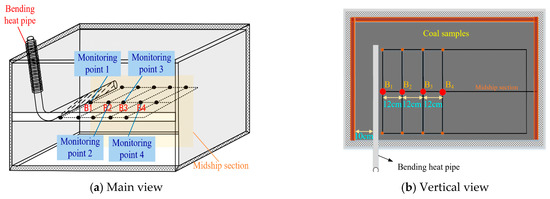
Figure 4.
Distribution of monitoring points.
Figure 5 and Table 2 show our analysis of the differences between the experimental and simulation results. Comparing the results in the experimental and simulation groups, it can be seen that most of the data are close to each other. Overall, the heat pipe’s heat transfer and cooling effect is mainly in areas 1–3 of the measuring point, which is consistent with the optimal heat transfer radius determined in the experiment. The maximum error of the simulation result is 1.2 °C, with a minimal error of 0.1 °C and the error value being in the acceptable range. This validates that the model can accurately simulate the heat pipe’s heat transfer and cooling process to a broken area in a coal pillar.
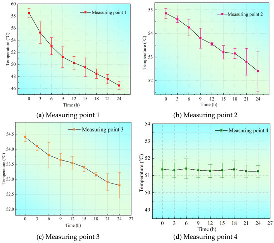
Figure 5.
Error bar analysis of experimental and simulation groups.

Table 2.
Comparison of experimental and simulation results.
4. Results and Discussion
4.1. The Effect of a Bending Heat Pipe on the Coal’s Temperature Field
Based on the presented parameters, the transient heat conduction simulation of the model was carried out. Our heat transfer simulation results for the bending heat pipe can be observed in Figure 6 and Figure 7. By comparing and analyzing variations in the internal temperature field of the coal body over time before and after the bending heat pipe was placed, as the heat transfer time increased, the bending heat pipe exerted an obvious cooling effect on the coal body. To intuitively show the effects of the heat pipe’s heat transfer and cooling, and according to the actual distribution of measurement points in the field experiment, the front, middle, and back sections inside the coal body were intercepted, and cloud maps of the temperature field changes over time in each section were plotted (Figure 7).
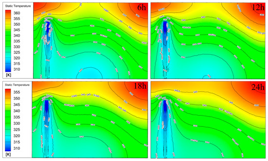
Figure 6.
Distribution of temperature fields in coal body upon heat transfer by heat pipe.
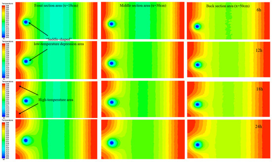
Figure 7.
Distribution of temperature fields in the front, middle, and back sections of the coal body upon heat transfer by the heat pipe.
Comparing the temperature field contours in each section area, it can be seen that they conform to the experimental findings. The coal body’s temperature near the bending heat pipe decreases significantly, forming a “saddle-shaped” low-temperature depression area. The temperature field within the high-temperature area has clearly been disturbed. The original heat conduction path inside the coal body changes, with heat transmitting into the external environment through the bending heat pipe. The temperature of the coal body outside the heat transfer radius of the bending heat pipe shows no change. In summary, the bent heat pipe significantly enhances heat dissipation in high-temperature regions in the coal crushing zone and has an impact on the overall temperature field distribution.
4.2. Effect of Spacing on Distribution Characteristics of Coal’s Temperature Field
4.2.1. Heat Transfer Effect of a 30 cm Spacing Between Bending Heat Pipes
Figure 8 is a simulation diagram showing the heat transfer effect induced by bent heat pipes on a broken zone in a coal pillar when the spacing between the pipes is 30 cm under the conditions of a non-uniform temperature field and a uniform temperature field at 60 °C. We selected the insertion position of the modeled heat pipe to set up a transverse section with an inclination of 10° (the tangent point coordinates are (0,0,29), (120,0,29), and (120,60,18), respectively), and drew the transverse slice diagram of the coal’s temperature after the heat transfer by the heat pipe under two temperature field conditions, as shown in Figure 8a.

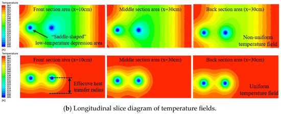
Figure 8.
The temperature field distribution when the bending heat pipe spacing is 30 cm under the two temperature fields.
According to Figure 8a, at a spacing of 30 cm, at which the distance between the two bending heat pipes is far smaller than the effective coverage of its core heat transfer radius, both bending heat pipes can have an obvious cooling effect on the temperature field in a coal pillar’s crushing zone. A saddle-shaped low-temperature depression is formed around the bending heat pipe, with the heat pipe absorbing and transferring heat efficiently in the local range. From Figure 8b, we can see that at a bending heat pipe spacing of 30 cm, the high-temperature heat source near the heat pipe in each section of the coal pillar’s crushing zone is effectively reduced. The heat transfer within the middle area in the two bending heat pipes increases relative to the oxidation heat that is released by the coal body, and heat accumulation in the coal pillar’s crushing zone is obviously suppressed within 24 h.
In order to monitor the law of temperature changes in the coal body around a heat pipe before and after introducing the bending heat pipe arrangement more accurately, three 120 cm three-dimensional transverse cross-sections (with the two-point coordinates of (0,10,31) and (120,10,31); (0,30,28) and (120,30,28); and (0,50,22) and (120,50,22)) were established on the three longitudinal sections, and the temperature change law of each section of the coal body under different temperature fields was drawn based on these, as shown in Figure 9 and Figure 10.

Figure 9.
Temperature change curves when the spacing between the bending heat pipes is 30 cm in a non-uniform temperature field.
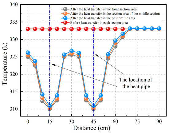
Figure 10.
Temperature change curves when the spacing between the bending heat pipes is 30 cm under a uniform temperature field.
Based on Figure 9, under a non-uniform temperature field, before the placement of the bending heat pipes, the temperature in the front, middle, and rear sections of the coal body is distributed in a gradient concave shape. After heat transfer for 24 h, the temperature curve of the coal body near the heat pipe in each section fluctuates violently, showing a “wavy” up-and-down trend. When the spacing is 30 cm, because this is within the heat transfer radius of the heat pipe, the heat pipe continuously decreases the temperature of the surrounding coal body. The coal’s temperature around the two heat pipes in each section decreases from 52, 59, and 72 °C to 44.5, 48, and 52 °C, respectively, and the cooling efficiency is 14.4%, 18.6%, and 27.8%, respectively. However, in the coal body without a heat pipe, the coal temperature does not change significantly, because the accumulated heat cannot be lost. The temperature change curve for bent heat pipes with a spacing of 30 cm in a 60 °C uniform temperature field is shown in Figure 10. The temperature change is similar to the one described above. In the absence of heat transfer, the temperature curve transitions smoothly. Twenty-four hours after placing the bending heat pipes, the temperature on the curve fluctuates violently in a “wavy” pattern. As for the coal body, its temperature range decreases relative to that before heat transfer due to the bending heat pipes. The coal body’s temperature in each section that is sandwiched by the two heat pipes decreases by at most 22 °C and at least 8 °C. Due to the heat transfer and cooling of the bending heat pipe, the dangerous area of the coal pillar’s crushing zone shrinks along the end of the heat pipe, and heat accumulation within the crushing zone can be controlled.
4.2.2. Heat Transfer Effect of a 40 cm Spacing Between Bending Heat Pipes
Figure 11 presents a simulation diagram for the heat transfer effect of a broken zone in the coal pillar when the spacing between the bending heat pipes is 40 cm under the two temperature field conditions. The insertion position of the model heat pipe is selected to set up a transverse section with an inclination of 10° (the tangent point coordinates are (0,0,29), (120,0,29), and (120,60,18), respectively), and the transverse slice diagram of the coal’s temperature under two temperature field conditions is drawn as shown in Figure 11a. Three longitudinal temperature slices 10, 30, and 50 cm away from the coal body’s front wall are established as shown in Figure 11b.
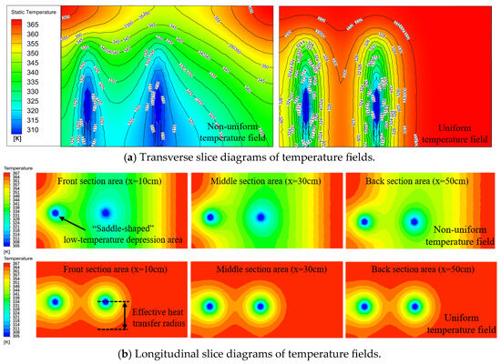
Figure 11.
Distribution of the two temperature fields at a bending heat pipe spacing of 40 cm.
According to our analysis, at a heat pipe spacing of 40 cm, since the distance between the two bending heat pipes is exactly within the effective coverage of their heat transfer radius, both bending heat pipes have a certain cooling effect on the temperature field in the coal pillar’s crushing zone. The diffusion inhibition effect of the isothermal line decreases slightly as the spacing between the heat pipes increases. The temperature of the high-temperature heat source in the middle section of both bent heat pipes declines, and the temperature contour is sunken along the heat pipe direction. Comparing the heat transfer effects of the two bending heat pipes under the condition of a non-uniform temperature field and a uniform temperature field, it can be concluded that when the spacing is 2 times the heat pipe’s heat transfer radius, heat accumulation in the coal body can be inhibited within 24 h.
To monitor the law of temperature changes in the surrounding coal body when the spacing between the heat pipes is 40 cm, three 120 cm three-dimensional transverse cross-sections (with the two-point coordinates of (0,10,31) and (120,10,31); (0,30,28) and (120,30,28); and (0,50,22) and (120,50,22), respectively) are set on the three longitudinal sections, and the law of temperature change of each section of the coal body under different temperature fields is drawn based on these, as shown in Figure 12 and Figure 13.

Figure 12.
Temperature change curves in a non-uniform temperature field when the spacing between bending heat pipes is 40 cm.
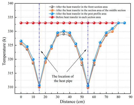
Figure 13.
Temperature change curve in a uniform temperature field when the spacing between bending heat pipes is 40 cm.
According to Figure 12, 24 h after the heat pipe heat transfer, the temperature curve of the coal body near the heat pipe in each section conforms to the changes described above, with a “wave”-like up-and-down change pattern. Due to the increasing distance between the two heat pipes, the amplitude of their cooling of the temperature in the area where they are sandwiched decreases slightly. The temperature of the coal in each section decreases from 52, 59, and 72 °C to 46, 52, and 62 °C, respectively, and the cooling efficiency is 11.5%, 11.9%, and 13.9%, respectively. The minimum temperature of the coal decreases by 6 °C, whereas the maximum temperature decreases by 10 °C. Figure 13 presents the temperature change curve in a uniform temperature field when the spacing between the bending heat pipes is 40 cm, which is similar to our analysis of the cooling curve of the non-uniform temperature field. As the distance between the two heat pipes increases, the cooling amplitude in the area decreases slightly, but the temperature range of the coal body can be controlled below the temperature range before heat transfer. The coal body’s temperature in each section decreases by 22 °C at most and 3.5 °C at least, and the cooling efficiency is 36.7% and 5.8%, respectively. Under heat pipe heat transfer and cooling, heat within the coal crushing zone near the bending heat pipe is removed by the heat pipe, and the temperature of the coal body decreases.
4.2.3. Heat Transfer Effect of a 50 cm Spacing Between Bending Heat Pipes
Figure 14 is a diagram of the simulated heat transfer effect in the broken zone in the coal pillar at a spacing of 50 cm between the bending heat pipes under the two temperature field conditions. The model heat pipe’s insertion position is selected to set a transverse section with an inclination of 10° (the tangent point coordinates are (0,0,29), (120,0,29), and (120,60,18)), and the transverse slice temperature diagram of the coal body under the two temperature field conditions is drawn as shown in Figure 14a. According to the same positions of the measuring points as before, during, and after the experiment, three longitudinal slice cloud images 10, 30, and 50 cm from the coal body’s front wall are created, respectively, as shown in Figure 14b.
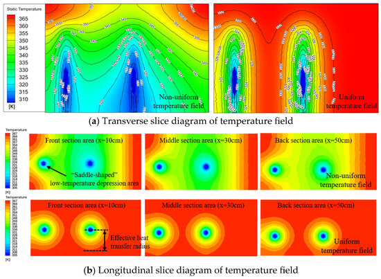
Figure 14.
The temperature field distribution in the two temperature fields when the spacing between bending heat pipes is 50 cm.
Based on Figure 14a,b, the heat transfer effect of the bending heat pipe on the coal around the heat source is also significantly weakened, because the spacing between the two bending heat pipes is greater than their heat transfer radius, and effective cooling of the coal heat source cannot be achieved under this spacing. Therefore, the heat pipe’s heat transfer and cooling effect is limited by the distance between the heat pipes’ heat transfer radii; consequently, the heat removal in the area between the two heat pipes is not sufficient to offset the heat generated by the oxidation of the coal body, and the accumulation of heat in the coal body cannot be controlled in time, meaning that the coal pillar’s crushing area cannot be cooled effectively.
To monitor the law of temperature changes surrounding the coal body when the spacing between the heat pipes is 50 cm, three 120 cm three-dimensional transverse cross-sections (with the two-point coordinates of (0,10,31) and (120,10,31); (0,30,28) and (120,30,28); and (0,50,22) and (120,50,22), respectively) are set on the three longitudinal sections, and the temperature change law of each section of the coal body under different temperature fields is drawn based on these, as shown in Figure 15 and Figure 16.

Figure 15.
Temperature change curves in a non-uniform temperature field when the spacing between bending heat pipes is 50 cm.
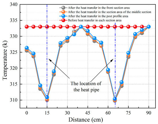
Figure 16.
Temperature change curves in a uniform temperature field when the spacing between bending heat pipes is 50 cm.
Based on Figure 15, 4 h after the heat transfer, the temperature curves of the coal body near the heat pipe in each section conform to the change described previously, with a “wave”-like up-and-down change pattern. Because the spacing between the heat pipes is greater than the heat transfer coverage of the two heat pipes, the amplitude of their cooling of the area in which they are sandwiched decreases substantially. The coal’s maximum temperatures within each section decreases from 52, 59, and 72 °C to 51, 53, and 65 °C, respectively, while the cooling efficiency is 1.9%, 10.2%, and 9.7%, respectively, with a slight temperature drop. Figure 16 shows the temperature change curve in a non-uniform temperature field for a spacing between bending heat pipes of 50 cm. From the peak value of the “wave”-like cooling curve, as the spacing increases again, the maximum amplitude of the cooling in the area sandwiched by the two bending heat pipes is 0 °C. Under this spacing, effective cooling and control of the coal’s temperature near the heat source by the heat pipes cannot be realized.
Combined with the above analysis results, the cooling effects of the bending heat pipe on each temperature field under different spacings are summarized in Table 3. It can be seen from this table that the heat transfer effect on the temperature field of the broken zone inside the coal pillar peaks at a spacing of 30 cm. The maximum cooling efficiency in the non-uniform temperature field and uniform temperature field is 36.7% and 27.8%, respectively. When the two heat pipes are separated by 50 cm, the cooling effect is reduced because of the limited heat transfer radius of the heat pipes. By comparing three spacings, two arrangement schemes of 30 cm and 40 cm are finally selected. In terms of costs, the spacing of 40 cm can not only ensure a better heat removal effect but also effectively reduce the cost. Therefore, the spacing of 40 cm can be used as the theoretical spacing between two bending heat pipes. In order to realize the effective removal of heat more quickly, the spacing range between 30 and 40 cm can be considered. With this spacing range, the heat pipes are more densely distributed, thereby increasing the contact area between heat pipes high-temperature areas within the coal body while improving the heat transfer efficiency.

Table 3.
Cooling efficiency of coal temperature field under different spacings.
5. Conclusions
In this paper, the heat transfer model of a bending heat pipe was constructed using Fluent numerical simulation. The heat transfer and cooling achieved by a single heat pipe in response to an oxidation heat source in a coal pillar were studied, as were the effects induced by different spacings between two bending heat pipes in terms of heat transfer and cooling of a non-uniform temperature field and a uniform temperature field. The effects induced by various heat pipe layout parameters on the heat transfer effect from a high-temperature heat source in a coal body were clarified. Our research results can provide a theoretical basis for the advanced prevention of the hidden danger of CSC in the process of narrow coal pillar mining. The main conclusions are as follows:
- (1)
- Through numerical simulation and experimental comparison, the maximal difference in temperature between the simulated temperature field of a bending heat pipe and the experimental temperature field under identical working conditions was 3.8 °C, which proves the feasibility of the model. It was further shown that the model can meet the expected demand of heat transfer and cooling by a bending heat pipe in mining engineering.
- (2)
- A heat transfer model of two bending heat pipes with different spacings of 30 cm, 40 cm, and 50 cm was established. Six different working conditions were established to simulate and analyze how the spacing between heat pipes affected their heat transfer effect in a coal pillar’s crushing zone. At 24 h after the heat transfer, the coal temperature curve of each section near the heat pipe displayed a “wave”-like variation trend. As the spacing between two bending heat pipes increased, heat transfer of the temperature field within the broken zone inside the coal body was obviously weakened.
- (3)
- The heat transfer effects induced by the three different spacings between bending heat pipes under two temperature field conditions were compared. The best heat transfer effect can be achieved at a spacing of 30 cm, with an efficiency of 36.7%. At a spacing of 50 cm, the temperature suppression effect was reduced because of the limited heat transfer radius of the bent heat pipe. Overall, 30–40 cm is the best spacing between bending heat pipes, achieving both a heat transfer effect and cost-effectiveness. A similar-ratio design based on this optimal spacing can be applied directly to a mining site, which can effectively decrease costs while ensuring heat transfer.
- (4)
- Our research results provide a theoretical reference for the use of bending heat pipes to inhibit the spontaneous combustion of coal pillars, which to a certain extent can lead to early prevention and control of the oxidation of heat sources in the broken area of coal pillars. Due to the length of our experimental period, the experimental conditions have certain objective limitations. In the future, this experiment can be optimized by prolonging the monitoring time and increasing the density of temperature monitoring points. In order to effectively prevent and control spontaneous combustion of coal pillars under actual mining conditions, the synergistic effect of multiple bending heat pipes, the phase change law of the working medium inside the heat pipes, and the field conditions should be studied in depth.
Author Contributions
Conceptualization, Supervision, and Formal analysis, J.G.; Writing (original draft), S.L.; Formal analysis, Y.W.; Methodology and Investigation, C.C.; Methodology and Investigation, Y.L.; Supervision and Formal analysis, L.W.; Conceptualization and Supervision, X.Z. All authors have read and agreed to the published version of the manuscript.
Funding
This work was supported by the Key R&D Project in Shaanxi Province (grant number 2025SFYBXM549 and 2025SFYBXM557) and the National Natural Science Foundation of China (grant numbers 52004209 and 52174198).
Data Availability Statement
The original contributions presented in this study are included in this article. Further inquiries can be directed to the corresponding authors.
Acknowledgments
The work described in this paper has not been submitted elsewhere for publication, in whole or in part, and all the authors listed have approved the enclosed manuscript.
Conflicts of Interest
The authors declare no conflicts of interest.
Abbreviations
The following abbreviations are used in this manuscript:
| CSC | Coal spontaneous combustion |
References
- Wang, Q.X.; Huang, Q.X.; He, Y.P.; Fan, D.L.; Chen, S.S.; Wang, W. Research on reasonable coal pillar staggered distance in shallow multi-seam mining. Disco. Appl. Sci. 2024, 6, 361. [Google Scholar] [CrossRef]
- Xu, Q.Y.; Bai, J.B.; Yan, S.; Wang, R.; Wu, S.X. Numerical Study on Soft Coal Pillar Stability in an Island Longwall Panel. Adv. Civ. Eng. 2021, 2021, 8831778. [Google Scholar] [CrossRef]
- Gu, W.; Zhang, H.; Han, Z.F.; Tang, H.K.; Pei, J.Y.; Wu, S.X.; Xu, D.L. Research on the Bearing Characteristics of Narrow Coal Pillars in Double-Roadway Excavation Under the Influence of Full Dynamic Pressure. Appl. Sci. 2025, 15, 7148. [Google Scholar] [CrossRef]
- Liu, Y.; Qi, X.Y.; Luo, D.Y.; Zhang, Y.Q.; Yin, D.X. Research on the Law of Coal Pillar Spontaneous Combustion and Fire Prevention and Control Technology. ACS Omega 2024, 9, 18973. [Google Scholar] [CrossRef]
- Ardehjani, E.A.; Ataei, M.; Sereshki, F.; Mirzaghorbanali, A.; Aziz, N. Impact of CO2 and methane adsorption and emission on coal’s mechanical properties and pillar stability: Implications for ECBM and CO2 sequestration. Energy 2025, 333, 137438. [Google Scholar] [CrossRef]
- Sun, L.L.; Yang, J.L.; Guo, Z.G.; Shi, Q.L.; Qi, G.S.; Zhou, F.G. Numerical and experimental Investigation of coal pillar crushing and spontaneous combustion in shallow and closely spaced coal seams. Adv. Power Technol. 2025, 36, 104848. [Google Scholar] [CrossRef]
- Zheng, W.C.; Yang, S.Q.; Li, W.Z.; Wang, J. Research of inorganic fire-extinguishing materials on preventing and controlling gas and coal spontaneous combustion in the narrow coal pillar and adjacent goaf. Fire Mater. 2020, 44, 660–672. [Google Scholar] [CrossRef]
- Zubov Vladimir, P.; Golubev Dmitrii, D. Prospects for the use of modern technological solutions in the flat-lying coal seams development, taking into account the danger of the formation of the places of its spontaneous combustion. J. Min. Inst. 2021, 250, 534–541. [Google Scholar] [CrossRef]
- Mária, P.; Andrej, K.; Milan, M.; Patrik, N. The Effect of Convection on the Thermal Power Change of Loop Thermosyphon. MATEC Web Conf. 2020, 328, 03008. [Google Scholar] [CrossRef]
- Pekur, D.V.; Nikolaenko, Y.E.; Kravets, V.Y.; Kozak, D.V.; Sorokin, V.M.; Nikolaienko, T.Y. Comparison of thermal characteristics of three modifications of gravity heat pipe with threaded evaporator at different inclination angles. Therm. Sci. Eng. Prog. 2023, 46, 102219. [Google Scholar] [CrossRef]
- Anand, R.S.; Li, A.; Huang, W.B.; Chen, J.W.; Li, Z.B.; Ma, Q.S.; Jiang, F.M. Super-long gravity heat pipe for geothermal energy exploitation - A comprehensive review. Renew. Sust. Energy Rev. 2024, 193, 114286. [Google Scholar] [CrossRef]
- Feng, C.; Gibbons, M.J.; Marengo, M.; Chandra, S. A novel ultra-large flat plate heat pipe manufactured by thermal spray. Appl Therm Eng. 2020, 171, 115030. [Google Scholar] [CrossRef]
- Patel, K. An efficient optimization and comparative analysis of ammonia and methanol heat pipe for satellite application. Energy Convers. Manag. 2018, 165, 382–395. [Google Scholar] [CrossRef]
- Qian, N.; Jiang, F.; Chen, J.J.; Fu, Y.C.; Zhang, J.Z.; Xu, J.H. Heat transfer enhancement by diamond nanofluid in gravity heat pipe for waste heat recovery. Funct. Diam. 2022, 2, 236–244. [Google Scholar] [CrossRef]
- Liu, L.M.; Guo, Z.A.; Du, Z.Y.; He, X.Q.; Gu, H.Y. Experimental research on the coupling heat transfer characteristics of the system components of the space heat pipe cooled reactor under the power variation conditions. Appl. Therm. Eng. 2025, 278, 127456. [Google Scholar] [CrossRef]
- Zhang, X.S.; Sun, H.W.; Huang, J.J.; Sun, P.W.; Wei, X.Y. Control Strategy Study for a Heat Pipe Cooled Nuclear Reactor. SSRN Electron. J. 2023, 190, 109849. [Google Scholar] [CrossRef]
- Zhang, X.F.; Zhou, X.X. Experimental Study on Wall Temperature and Heat Transfer Characteristics of Gravity Heat Pipe by Heat Input Power and Working Materials. Combust. Sci. Technol. 2023, 195, 2311–2326. [Google Scholar] [CrossRef]
- Zhang, X.G.; Wang, T.; Zhang, X.H.; Ge, S.C. Analysis of multiple factors influencing the efficiency of gravity thermal pipe waste heat recovery: A case study of heat accumulation management in spoil tips. Energy 2025, 322, 135526. [Google Scholar] [CrossRef]
- Sun, G.Y.; Wu, Y.; Gao, W. The Heat-Dissipation and Dehumidification System of the Hybrid Multi-Layer Gravity Heat Pipe Applied to Granary. Mod. Appl. Sci. 2019, 13, 76. [Google Scholar] [CrossRef]
- De León-Ruiz, J.E.; Beltrán-Chacón, R.; Carvajal-Mariscal, I.; Venegas, M.; De La Cruz-Ávila, M. Effect of vessel dimensional ratio on heat conveyance capabilities of gravity-assisted heat pipes: Theoretical and experimental approach. Therm. Sci. Eng. Prog. 2023, 45, 102091. [Google Scholar] [CrossRef]
- Dai, J.; Tian, Z.J.; Shi, X.Y.; Lu, Y.; Chi, W.L.; Zhang, L. Research progress on gravity heat pipe technology to prevent spontaneous combustion in coal storage piles. MRS Commun. 2024, 14, 480–488. [Google Scholar] [CrossRef]
- Zhai, Y.; Ling, Z.K.; Zhao, X.; Dong, Z.F. Effects of Structure Parameters of Gravity-Type Heat Pipe on Heat Transfer Characteristics for Waste Heat Recovery from Mine Return Air. Energies 2024, 17, 6495. [Google Scholar] [CrossRef]
- Xie, A.H.; Zhang, B.L.; Zhang, X.H.; Zhang, Y.X.; Cao, Z.K. Simulation Study on the Influence of Chimney Structure on the Efficiency of Gravity Heat Pipes for Controlling Spontaneous Combustion in Coal Waste Rock Piles. Combust. Sci. Technol. 2025, 197, 2578–2597. [Google Scholar] [CrossRef]
- Tong, J.M.; Zhang, Y.B.; Zhao, X.H.; Shi, H.; Zhang, Y.H. Influence of heat pipe layout parameters on the cooling effect of spontaneous combustion coal gangue dumps. Sci. Rep. 2024, 14, 27056. [Google Scholar] [CrossRef]
- Senthil Kumar, R.; Vaidyanathan, S.; Sivaraman, B. Effect of copper nanofluid in aqueous solution of long chain alcohols in the performance of heat pipes. Heat Mass Transf. 2015, 51, 181–193. [Google Scholar] [CrossRef]
- Xiao, Y.; Zhong, K.Q.; Tian, J.Y.; Yin, L.; Tian, Y.; Shu, C.M. Thermal extraction from a low-temperature stage of coal pile spontaneous combustion by two-phase closed thermosyphon. J. Therm. Anal. Calorim. 2021, 144, 587–597. [Google Scholar] [CrossRef]
- Wei, G.M.; Ma, L.; Wang, Z.P.; Wen, H.; Guo, R.Z.; Yu, W.Z.; Liu, S.M. Key Parameters of Preventing Spontaneous Combustion of Coal Stockpile Based on Heat Transfer Technology by a Heat Pipe. Combust. Sci. Technol. 2022, 194, 2916–2932. [Google Scholar] [CrossRef]
- Gselman, U.; Peršak, V.; Goričanec, D. Numerical Analysis of Low-Enthalpy Deep Geothermal Energy Extraction Using a Novel Gravity Heat Pipe Design. Sustainability 2024, 16, 6660. [Google Scholar] [CrossRef]
- Guo, J.; Chen, C.M.; Wen, H.; Cai, G.B.; Liu, Y. Prediction model of goaf coal temperature based on PSO-GRU deep neural network. Case Stud. Therm. Eng. 2023, 53, 103813. [Google Scholar] [CrossRef]
- Wang, J. Numerical Simulation Study on Effect of Gravity Heat Pipe on Distribution of Coal Fired Combustion Spontaneous Temperature Field; Xi’an University of Science and Technology: Xi’an, China, 2018. [Google Scholar]
- Chen, Q.H.; Sun, M.H.; Su, G.Y. Influence of Gravity Heat Hipe on Temperature Field in Coal Pile. Saf. Coal Mines 2018, 49, 211–214. [Google Scholar] [CrossRef]
- Li, B. Research on Thermodynamic Characteristies and Heat Transfer Method of Uncontrolled Fire in Coal Gangue Dump; Xi’an University of Science and Technology: Xi’an, China, 2017. [Google Scholar]
- Lu, X.; Liu, J.; Gao, L.H.; Xiao, Y.; Tong, X.L.; Deng, J. Experimental investigation on thermal-electric characteristics of curved thermosyphon-thermoelectric generator in waste heat recovery of coal spontaneous combustion. Appl. Therm. Eng. 2024, 244, 122638. [Google Scholar] [CrossRef]
Disclaimer/Publisher’s Note: The statements, opinions and data contained in all publications are solely those of the individual author(s) and contributor(s) and not of MDPI and/or the editor(s). MDPI and/or the editor(s) disclaim responsibility for any injury to people or property resulting from any ideas, methods, instructions or products referred to in the content. |
© 2025 by the authors. Licensee MDPI, Basel, Switzerland. This article is an open access article distributed under the terms and conditions of the Creative Commons Attribution (CC BY) license (https://creativecommons.org/licenses/by/4.0/).