Abstract
This paper investigates the multi-objective siting and sizing problem of a transformer–energy storage deeply integrated system (TES-DIS) that serves as a grid-side common interest entity. This study is motivated by the critical role of energy storage systems in generation–grid–load–storage resource allocation and the superior capability of artificial intelligence algorithms in addressing multi-dimensional, multi-constrained optimization challenges. A multi-objective optimization model is first formulated with dual objectives: minimizing voltage deviation levels and comprehensive economic costs. To overcome the limitations of conventional methods in complex power systems—particularly regarding solution quality and convergence speed—an enhanced Q-learning with hybrid guidance algorithm is proposed. The improved algorithm demonstrates strengthened local search capability and accelerated late-stage convergence performance. Validation using a real-world urban power grid in China confirms the method’s effectiveness. Compared to traditional approaches, the proposed solution achieves optimal TES-DIS planning through autonomous learning, demonstrating (1) 70.73% cost reduction and (2) 89.85% faster computational efficiency. These results verify the method’s capability for intelligent, simplified power system planning with superior optimization performance.
1. Introduction
The accelerating integration of distributed renewable energy sources [1,2] and increasingly pronounced peak load characteristics [3,4] have led to multipolar growth in electricity demand. This trend exposes conventional power grids to critical challenges, including transformer capacity/load ratio imbalances, power quality degradation, and insufficient transmission capacity [5]. Against this backdrop, the large-scale deployment of energy storage technologies and the intelligent transformation of grid infrastructure present new opportunities for power transformer modernization.
As a core component of power systems, power transformers can achieve enhanced reliability, controllability, and renewable energy accommodation capability through deep integration with energy storage systems. Such integration facilitates seamless “generation-grid-load-storage” coordination and supports real-time grid optimization [6]. While existing research has extensively investigated standalone energy storage integration, studies on hybrid systems combining storage with conventional power equipment remain limited. Current innovations like digital energy storage [7], mobile storage [8,9], shared storage [10,11,12], and cloud storage [13,14] primarily focus on economic aspects, neglecting the active power regulation capabilities of storage devices and their synergistic potential with transmission/distribution equipment. The proposed transformer–energy storage deeply integrated system (TES-DIS) establishes virtual power delivery nodes to simultaneously address renewable integration [15], power quality enhancement [16], and capacity expansion [17].
With the development of computer technology and modern intelligent optimization technology, the planning of energy storage equipment in distribution networks has evolved from the initial manual screening method to an automatic generation of station sites through computer calculation. The optimization methods have also risen from traditional mathematical optimization methods to modern intelligent optimization algorithms. Modern optimization methods for energy storage planning have evolved from manual site selection to computational automation. However, prevailing intelligent algorithms exhibit fundamental limitations when handling the high-dimensional discrete–continuous hybrid action space of grid–storage co-planning. Genetic Algorithms (GAs) suffer from slow convergence (>500 iterations) due to redundant binary encoding of discrete variables (e.g., transformer tap positions) and weak dynamic constraint handling (e.g., SOC boundaries) [18]. Particle Swarm Optimization (PSO) tends toward premature convergence when optimizing mixed-integer variables (e.g., storage sizing), as truncation operations disrupt gradient information flow [19]. Classical Q-learning wastes > 60% iterations on physically invalid actions (e.g., conflicting charge/discharge commands) and struggles with delayed rewards in sparse grid environments [20]. This trilemma of computational inefficiency, solution infeasibility, and domain knowledge neglect necessitates novel algorithmic frameworks that embed grid physics intrinsically.
To address these gaps, this paper proposes an enhanced reinforcement learning framework for TES-DIS multi-objective siting and sizing. The key innovations include the following:
- (1)
- Reward shaping incorporating grid physical constraints.
- (2)
- Dynamic action space pruning to balance exploration–exploitation.
- (3)
- Transformation of passive devices into grid-proactive co-benefit entities.
Case studies using real-world Chinese urban grid data validate the framework’s effectiveness.
2. Proposed System Configuration
2.1. Q-Learning Fundamentals
Q-learning is a model-independent reinforcement learning algorithm proposed by Watkins based on temporal difference that uses the state–action pair value function Q(s,a) for value function iteration. It is also known as off-policy TD learning. The iterative formula of Q-learning is shown as
where st denotes the system state (e.g., nodal voltages, transformer tap positions, ESS SOC), at the action (e.g., adjusting tap ratios or ESS charging power), α the learning rate, and γ the discount factor. While effective in discrete decision spaces, its application to TES-DIS configuration optimization faces three critical limitations:
- (1)
- Curse of Dimensionality: The joint state–action space of transformer–ESSs scales exponentially with network size (e.g., 30-bus system > 105 states).
- (2)
- Slow Convergence: Random exploration (ϵ-greedy) in sparse-reward environments wastes >60% iterations on invalid actions (e.g., violating SOC limits) [21].
- (3)
- Physical Constraint Ignorance: Standard reward functions rt fail to embed grid operational rules (e.g., voltage safety margins).
2.2. Hybrid Guidance Mechanism
To address these challenges, we propose two innovations integrated into the Q-learning framework:
- (1)
- Knowledge-Guided Exploration
Domain-specific rules dynamically adjust the exploration policy:
- (a)
- Reward Shaping: Augment immediate reward rt with feasibility indicators, such as equipment investment costs, reduction in network losses, voltage deviation, renewable energy generation outputs, and load demand are considered. Weights are then assigned to these feasibility indicators based on the specific application scenario.
- (b)
- Adaptive ϵ-Decay: Reduce random exploration probability ϵ when gradient ∇Q(st) exceeds threshold τ:
This prioritizes exploitation near high-value regions.
- (2)
- Action Space Pruning
Real-time elimination of physically infeasible actions using
where ggrid(a) is the power flow violation degree (e.g.,||ΔV||2); hESS(a) is the state-of-charge trajectory projection.
2.3. Advantage Analysis
The proposed enhancements deliver three key benefits: accelerated convergence through action pruning, which reduces average training episodes compared to conventional Q-learning; enhanced engineering feasibility, where knowledge-guided rewards eliminate operational constraint violations during exploration; and improved adaptability, enabling extension to other grid-integrated assets (e.g., PV–storage hybrids) through modifications to ggrid(a) and other feasible region parameters.
3. System Modelling
3.1. Optimization Model for Siting and Sizing of the TES-DIS
The TES-DIS enhances the dynamic loading capability of transformers during emergency load scenarios by leveraging the flexible charging and discharging characteristics of energy storage units. This enhancement facilitates the deferral of transformer capacity upgrades, enables arbitrage between peak and off-peak electricity prices, and provides ancillary service revenues. Given the high initial investment cost of the energy storage system (including battery units, power conversion systems, and monitoring equipment), while exhibiting low marginal adjustment costs, this model focuses on the coordinated techno-economic optimization of TES-DIS planning and operation. This optimization is performed under predetermined conditions influenced by load characteristics, policy factors, and construction decisions. Consequently, the core objectives for this section are formulated as the minimization of the total system operating cost and voltage deviation, while grid security constraints are strictly enforced. This approach achieves in-depth coordination between the energy storage capacity and the transformer’s dynamic capability.
- (1)
- Objective Function
The optimal siting and sizing problem for the TES-DIS necessitates coordinated consideration of multiple factors, such as operational economy and minimization of active power losses. Consequently, a comprehensive operational model addressing multi-dimensional requirements is formulated. Based on this analysis, the following multi-objective optimization framework is established for the operational stage:
Economic Perspective: A comprehensive economic cost index is incorporated.
Technical Perspective: Voltage profile quality at load buses is optimized, quantified through an average voltage deviation index. The overall objective function F is defined as
where f1 and f2 represent the comprehensive economic cost index and average voltage deviation index, respectively.
- (a)
- Comprehensive Economic Cost Index (f1)
The first objective function, the comprehensive economic cost index, is calculated as
where i denotes the transformer node index, N is the total number of transformers in the system, and CEi is the comprehensive economic cost at transformer node i.
CEi extends the conventional annualized Csc by incorporating revenues from peak-valley arbitrage and ancillary services enabled by the energy storage unit’s operational strategy of charging during off-peak periods and discharging during peak periods:
where Cdischarge is the electricity price during grid peak periods when energy storage discharges; Ccharge is the electricity price during grid off-peak periods when energy storage charges; ηcharge and ηdischarge are the charging and discharging efficiencies of the energy storage unit, respectively; and Esc,i is the battery rated capacity of the i-th TES-DIS. The traditional annual average cost calculation can be referred to in [21].
- (b)
- Voltage Deviation Index (f2)
Voltage deviation refers to the magnitude by which the actual voltage at electrical equipment deviates from the nominal system voltage due to load variations or changes in power system operating conditions. Inappropriate siting or sizing of TES-DIS may exacerbate node voltage deviations during large-scale integration of high-capacity energy storage, potentially exceeding limits. This can compromise the safety and economic operation of electrical equipment, affect product quality and yield, and even cause equipment damage. To quantitatively assess power supply voltage quality and mitigate the impact of system uncertainties on TES-DIS optimization results, the average voltage deviation index f2 is introduced. This index improves nodal voltage distribution within the optimization outcomes, thereby enhancing operational performance. The voltage deviation index Foffset is formulated as
where Nnode is the number of system nodes, UN is the nominal voltage, Um,t is the voltage magnitude at node m and time t, and T is the set of all time intervals.
- (2)
- Siting and Sizing Constraints
The following constraints must be satisfied for this optimization problem:
- (a)
- Power Flow Constraints
- (b)
- Voltage Angle Constraints
The upper and lower limits of the node phase angle are ±π/6.
- (c)
- Power Balance Constraints
- (d)
- Line Thermal Constraints
After optimal allocation, the power transmitted by each line must not exceed its maximum allowable transmission capacity. The line capacity constraint can be expressed as
Here, presents the transmission capacity limit of the line.
- (e)
- Node Voltage Constraints
Considering the impact of TES-DIS integration on voltage, to ensure the safe, economical operation of electrical equipment and the power system, as well as to maintain production output and quality, the node voltage must satisfy the following network security operation constraints:
where = 0.95 and = 1.05 represent the upper and lower limits of node voltage, respectively.
- (f)
- Energy Storage System Constraints
The modeling of energy storage systems necessitates a comprehensive consideration of various constraints across multiple time periods. These constraints primarily encompass limitations on the charging/discharging states, charging/discharging power, state of charge (SOC), and capacity of the energy storage system. It is noteworthy that these constraints are specifically tailored for the optimization configuration model of the TES-DIS.
where and represent the charging and discharging states, respectively, of the energy storage system equipped in the e-th TES-DIS during the t-th time period. When , the ESS e is charging during the t-th time period; when , the ESS e is discharging during the t-th time period. and are the lower bounds of the charging and discharging power, respectively, for ESS e, while and are the upper bounds. and denote the charging and discharging power, respectively, of ESS e during the t-th time period. represents the energy level of ESS e during the t-th time period. and are the efficiency coefficients for charging and discharging, respectively, of ESS e, typically with ; represent the lower and upper bound coefficients, respectively, of the state of charge (SOC) for and , which are the lower and upper bounds, respectively, of the capacity considering factors such as the lifespan of ESS e.
- (g)
- Transformer Capacity Expansion Constraints
After optimization configuration, the capacity of the transformer replaced under the traditional expansion strategy should be larger than that of the original transformer, while not exceeding the maximum capacity limit after expansion.
where SN,max represents the maximum rated capacity limit of the transformer after adopting the expansion strategy; denotes the rated capacity of transformer i after expansion; and SN,i is the original rated capacity of transformer i.
3.2. Optimization Model for Siting and Sizing of the TES-DIS
- (1)
- Algorithmic Framework
The optimal siting and sizing problem for TES-DIS constitutes a high-dimensional, nonlinear, and strongly constrained combinatorial optimization problem. Its solution space, formed by discrete installation locations and continuous/discrete capacity configurations, exhibits combinatorial explosion. Traditional optimization methods (e.g., linear/nonlinear programming, heuristic algorithms) face significant challenges:
- (a)
- Curse of Dimensionality: In large-scale practical grids, candidate locations increase combinatorially with system size. When coupled with continuous/discrete capacity variables, the solution space renders exhaustive search or conventional metaheuristics (e.g., Genetic Algorithms, Particle Swarm Optimization) computationally intractable.
- (b)
- Dynamic Dependencies: TES-DIS operational strategies (charging/discharging) are affected by real-time electricity prices, load fluctuations, and renewable generation outputs. Accurate benefit assessment requires long-term simulation of multi-factor dynamic interactions, which static optimization cannot adequately address.
- (c)
- Exploration–Exploitation Trade-off: Standard methods (e.g., ϵ-greedy Q-Learning) exhibit inefficient random exploration in vast spaces, susceptibility to local optima, slow convergence, and unstable solution quality.
To address these challenges, an Enhanced Q-Learning with Hybrid Guidance (EQL-HG) algorithm is proposed. Its advantages are threefold:
- (a)
- Markov Decision Process (MDP) Framework: Directly maps the hybrid decision process (discrete actions for siting, continuous/discrete actions for sizing), inherently mitigating dimensionality concerns.
- (b)
- Reward Function Design: Enables autonomous learning of the TES-DIS’s long-term comprehensive value within dynamic environments.
- (c)
- Harmonizing Function H(s,a): Nodal electrical properties are evaluated to strategically guide exploration toward high-potential regions, with its weighting factor adaptively tuned during the learning process. This tuning progresses from prioritizing heuristic exploration for rapid identification of promising regions in initial phases to emphasizing exploitation of high-Q-value actions for refined optimization in final phases. Consequently, search efficiency and solution quality are significantly enhanced while premature convergence is prevented. Crucially, the integration of grid prior knowledge actively constrains the effective search space, enabling tractable optimization for large-scale practical power systems.
- (2)
- Key Algorithmic Innovations
The proposed strategy achieves multi-objective fusion at the action selection level through the following key innovations:
- (a)
- Reward Function Design
A multi-objective reward function is formulated by integrating economic and technical indicators:
where Cinv denotes equipment investment cost; ΔPloss is the reduction in active power losses, ΔV indicates voltage deviation magnitude; PREs and Pload are renewable energy output and load demand, respectively; and is the constraint violation penalty term.
Constraint violations encompass voltage limit violations (V < 0.95 p.u. or V > 1.05 p.u.), transmission line thermal limit violations, and protection maloperation risks.
- (b)
- Heuristic Function H(s,a) Design (Core Enhancement)
A heuristic function H(s,a) is incorporated into the baseline action–value function. Action selection is then jointly guided by the augmented function Q(s,a) + H(s,a), where H(s,a) encodes domain-specific rules for strategic exploration.
The heuristic function H(s,a) is formulated as
where dₘ denotes the electrical distance from node m to substation transformers, σₘ represents the load fluctuation rate at node m, and and indicate renewable generation output and load demand at node m, respectively.
The weighting coefficients ωi employ an adaptive annealing scheme:
where is the initial weight and k denotes the training episode index. The adoption probability β controls heuristic-guided action selection: when a random number ξ~U [0, 1] satisfies ξ < β, heuristic-suggested actions are adopted; otherwise, actions are selected based solely on Q-values.
To transition from exploration to exploitation, β is monotonically decayed from 0.8 to 0 during training:
where max is the maximum training episodes. This design prioritizes heuristic exploration during initial phases while emphasizing Q-value exploitation in later stages.
- (c)
- Enhanced Action Selection Strategy
The Boltzmann action selection is modified as
where H(s,a) denotes the heuristic merit function and η scales its influence. The temperature coefficient τ controls exploration intensity through logarithmic decay:
- (3)
- Cascade Analysis
Step 1: Initialize the Q-table, initial parameters, and the maximum number of training iterations.
Step 2: Reset the environment, start a new round of training, and reset the environment to the initial state S0.
Step 3: Select action at initial state S0 based on the current state and policy.
Step 4: Execute action at the initial state S0.
Step 5: Calculate and return the immediate reward, and transition to the new state St+1.
Step 6: Update the Q-value based on the reward Rt and the new state St+1.
Step 7: Update the state.
Step 8: Check for convergence; if not converged, return to Step 2.
Step 9: Output the training results.
4. Case Study
4.1. Case Study Setup
To ensure the reproducibility of the proposed Enhanced Q-Learning with Hybrid Guidance (EQL-HG) algorithm, the algorithmic hyperparameters essential for reproducing the results are delineated below. The learning rate (α) and discount factor (γ) were set to 0.1 and 0.95, respectively. The initial exploration rate ϵ0 was 0.8, following an exponential decay schedule with a decay rate of 0.995 per episode until a minimum of 0.05. The Boltzmann temperature was initialized at 1.0. The heuristic function weights were initialized as = 1/3 for the electrical distance, load fluctuation rate, renewable generation, and load demand indicators, respectively, and were adaptively annealed during training. The penalty coefficients for voltage, line thermal, and state-of-charge (SOC) violations were set to 1000, 500, and 200 per unit violation, respectively. The training consisted of 1000 episodes with a maximum of 200 steps each, and convergence was assumed when the relative change in the total cost was less than 1% over 50 consecutive episodes.
To verify the effectiveness of the proposed model and algorithm, this section conducts a comparative cost–benefit analysis and applicability assessment of different capacity expansion strategies based on a real 220/110 kV urban high-voltage distribution network, implemented in MATLAB R2019b. The actual urban grid consists of seven 220 kV substations (Nodes 1–7), each with a capacity of 2 × 120 MW, functioning as hub nodes receiving power from the extra-high-voltage grid. Thirty-two 110 kV substations (Nodes 8–39), each with a capacity of 2 × 30 MW, serve as load center substations distributing power to medium-voltage networks. For computational simplicity, the conductor configurations are simplified according to common engineering practices: LGJ-400 is adopted for 220 kV transmission lines between substations, LGJ-240 for connections between 220 kV and 110 kV substations, and LGJ-185 for 110 kV interconnection lines. The system topology is illustrated in Figure 1.
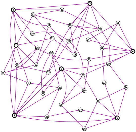
Figure 1.
Diagram of an actual 220/110 kV urban power grid.
The electricity prices for energy storage charging and discharging during off-peak and peak periods are set as Ccharge = 500 (yuan/MW·h) and Cdischarge = 1000 (yuan/MW·h), respectively. The charge/discharge efficiency of the storage unit is ηcharge = ηdischarge = 90%. Given the high replacement costs of battery storage, user demand, and the designed service life of the storage system, this case study does not consider the number of storage system replacement cycles. For the charge/discharge power of the storage system, constraints are imposed based on .
The load data from the past five years in the actual system are adopted. The annual load profile has an hourly resolution (8760 points) to capture daily and seasonal variations. The current annual load profile of the transformers is predicted based on the observed trend with an annual load growth rate of 3%. The load after five years of continuous growth is used as the input data for the system. Key characteristics of the aggregated system load include the following: Annual peak load: ~980 MW. Load factor: ~0.72. Peak-to-Valley difference: ~380 MW. The load at 110 kV nodes follows correlated profiles, with commercial-centric substations exhibiting pronounced evening peaks and industrial-centric substations showing flatter, higher daytime loads.
Boundary Conditions and Assumptions: It is assumed that no utility-scale energy storage assets were pre-existing in the network, and thus the proposed TES-DISs are considered new, incremental investments. The base case scenario incorporates a moderate penetration of distributed renewable generation—primarily rooftop PV—aggregated at their parent 110 kV substations, with a total installed renewable capacity of approximately 15% of the peak load (~147 MW). The connections at the 220 kV substations to the upper-level grid are modelled as ideal voltage sources with unlimited capacity, reflecting a strong interconnection, thereby allowing for the optimization to focus primarily on internal distribution constraints.
4.2. Optimal Configuration and Benefit Comparison of Different Capacity Expansion Strategies
To demonstrate the superiority of the proposed method, a conventional emergency capacity expansion strategy is established as a comparative case. This strategy, based on the short-term overload operation characteristics of transformers, allows for temporary overloading during peak load periods to meet power supply demands, representing one of the typical approaches for distribution network expansion. However, prolonged or frequent overload operation may accelerate transformer insulation aging, reduce equipment lifespan, and increase operational risks. This section conducts a comparative analysis between the conventional emergency expansion strategy and the proposed transformer-storage collaborative expansion method, focusing on load optimization effectiveness, economic efficiency, and technical feasibility. The results validate the potential value of the storage-integrated expansion model in enhancing grid safety and economic performance.
The optimal configuration scheme of the proposed energy storage system is illustrated in Figure 2 (the conventional emergency expansion strategy is not displayed as it does not involve energy storage deployment). Optimization results indicate that energy storage systems are primarily concentrated at 110 kV substation nodes, reflecting more pronounced power supply pressure at this voltage level during peak load periods. Further analysis incorporating actual urban grid load data reveals that the spatial distribution of energy storage nodes strongly correlates with key indicators such as regional load density and peak–valley differentials. Notably, energy storage capacity is significantly higher in areas with concentrated commercial and industrial loads. These findings not only verify the rationality of the optimization model but also provide critical insights for future urban grid energy storage planning.
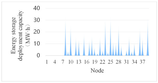
Figure 2.
Energy storage configuration scheme.
A comparison of the maximum overload coefficients for each transformer between the conventional emergency capacity expansion method and the proposed approach is presented in Figure 3.
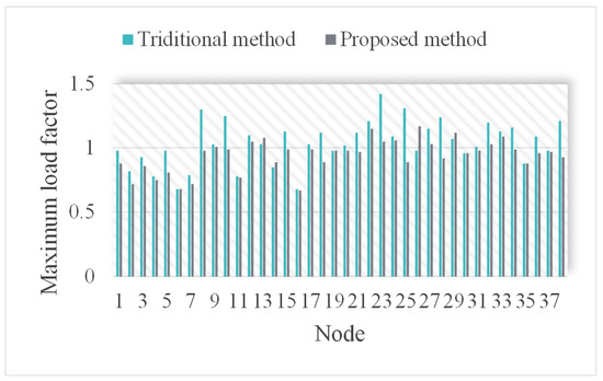
Figure 3.
Maximum overload coefficients of transformers under different capacity expansion methods.
As illustrated in Figure 3, the proposed transformer–energy storage coordinated optimization method significantly reduces the maximum overload coefficients across all transformers in the system compared to the conventional approach, with a maximum reduction of up to 37.2% (actual values vary depending on system power flow and nodal load conditions). This improvement is primarily attributed to the discharge support provided by the energy storage system during peak load periods, which effectively shares the power supply burden of the transformers.
The intelligent dispatch of energy storage units not only reduces transformer operating load ratios but, more importantly, extends equipment service life while enhancing the grid’s emergency power supply capability. These quantitative results demonstrate the technical feasibility of the transformer–storage coordinated optimization scheme in addressing overload issues in distribution networks, offering a novel technical pathway for improving power grid resilience.
Table 1 presents a comparison of economic indicators between conventional transformer capacity expansion and the proposed transformer–energy storage coordinated expansion scheme. The analysis demonstrates that the proposed method reduces total costs by 70.73% compared to the conventional approach, demonstrating significant economic advantages.

Table 1.
Capacity expansion costs of different methods.
This cost reduction primarily stems from the energy storage system’s effectiveness in mitigating long-term transformer overloading conditions. The implementation reduces the average annual transformer load rate from 141% to 103.8%, thereby substantially decreasing operation/maintenance costs and additional capacity expansion costs associated with severe overloading. Furthermore, the peak-shaving and valley-filling capabilities of the energy storage system delay the need for transformer capacity upgrades by an estimated 3–5 years.
Although the energy storage system requires additional initial investment, the resultant operational cost savings and deferred investment needs lead to markedly lower life-cycle costs. These findings robustly validate the techno-economic superiority of the proposed method in addressing rapid load growth, offering a more cost-effective innovative solution for distribution network expansion.
In summary, the proposed method outperforms conventional emergency expansion strategies in both technical feasibility and economic efficiency, providing a new approach for sustainable urban grid development.
4.3. Comparison of the Results of Different Optimization Algorithms
Given that a single optimization experiment may be affected by initial parameters or random perturbations, this study conducted 50 independent repeated experiments on both the traditional algorithm and the improved algorithm under identical experimental conditions to ensure the statistical significance of the results. As shown in Table 2, both algorithms can effectively generate distribution network capacity expansion optimization schemes that meet the constraint conditions, and the optimized schemes are significantly superior to the traditional capacity expansion method proposed in Case 4.2 in terms of cost-effectiveness.
Table 2.
Comparison of results of the two algorithms.
However, in-depth analysis reveals significant differences in computational performance between the two algorithms: under the premise that the optimization effects are comparable (with the relative errors of key indicators controlled within 5%); the average computation time of the improved algorithm is reduced by 89.85% compared with the traditional algorithm, demonstrating a significant efficiency advantage. This phenomenon can be attributed to the reward function and heuristic function H(s,a) mechanism introduced in the improved algorithm, which reconstructs the iterative convergence path, greatly reduces redundant computation steps, and thus significantly improves the solution speed while ensuring the optimization quality.
A further comparison of various technical and economic indicators in the optimization results reveals that the improved algorithm performs comparably to the traditional algorithm in terms of core parameters such as energy storage configuration capacity, total capacity expansion cost, and average load rate of transformers (in essence, each capacity expansion result is a repetition of Case 4.2; due to space constraints, the detailed capacity expansion results of each node are not presented here, with only the algorithm speed being compared), which verifies the reliability of its optimization effect. It is worth noting that the average capacity expansion cost of the improved algorithm is slightly lower than that of the traditional algorithm (with a reduction of approximately 2.3%). This difference further suppresses the node voltage deviation caused by energy storage access. As shown in the data in Table 2, the difference in the average voltage deviation between the two algorithms is only 0.0062 p.u., which can be considered statistically equivalent within the 95% confidence interval. Therefore, the results of the average voltage deviation are deemed approximately equal.
In addition to the comparison with the improved Q-learning algorithm, Table 2 also includes a comparison with the PSO algorithm. The results demonstrate that PSO performs significantly slower than the proposed method in handling this type of problem, with an average computation time approximately 20 times longer. This discrepancy can be attributed to PSO’s computational logic and convergence behavior. Although PSO achieves a reduction in the transformer load rate comparable to that of the proposed method, the resulting solutions incur higher economic costs on average. We hypothesize that this may be due to PSO’s tendency to become trapped in local optima—a common issue associated with this algorithm. Since this phenomenon was consistently observed across multiple experimental runs and is not an isolated occurrence, it can be concluded that the proposed method holds a clear advantage over PSO in tackling this category of problems.
Figure 4 further illustrates the results of the sensitivity analysis examining the impact of energy storage costs and load conditions on the total cost. Using the data from Table 1 as the baseline (unit 1), the energy storage costs and load levels were adjusted to 0.96–1.16 times their original values, respectively. The total cost was then calculated as a multiple of the baseline value of 19,740,000. The results are presented in multiplicative form, and thus no unit is associated with the values.
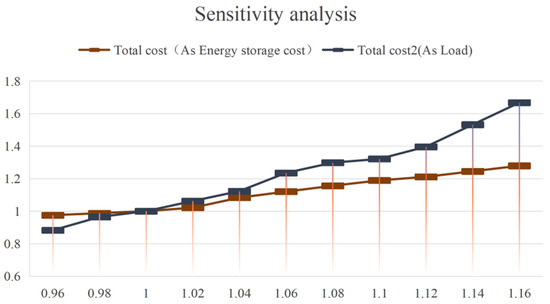
Figure 4.
Sensitivity analysis of energy storage costs and load conditions on total cost.
As can be observed from the figure, an increase in either energy storage costs or grid load levels leads to a rise in the total cost, with the increase in load level having a particularly notable effect. The primary reason for this phenomenon is that higher load levels not only raise the investment cost of the energy storage system but also increase the operating cost of transformers. This trend aligns with economic principles observed in practical operations, thereby further validating the rationality of the analytical results.
To address the trade-off dynamics between the economic and technical objectives, the Pareto-optimal front was generated using the ε-constraint method. As depicted in Figure 5, a clear conflict between the comprehensive economic cost and the maximum voltage deviation is observed. The Pareto front exhibits a characteristic decreasing trend, confirming that achieving higher voltage stability (lower deviation) necessitates a higher economic investment. The solution obtained by the proposed EQL-HG algorithm converges near the “knee point” of the front, which represents the most cost-effective compromise. This provides planners with critical insight: opting for solutions on the left side of the knee point yields lower costs but higher voltage deviations, while solutions on the right side offer superior voltage quality at a premium cost.
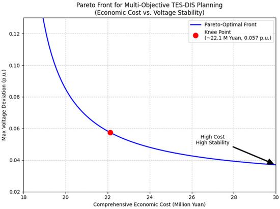
Figure 5.
Pareto front for the multi-objective optimization of TES-DIS planning.
In summary, the algorithm proposed in this paper, while maintaining the computational effectiveness of the proposed model, has achieved a breakthrough improvement in computational efficiency through innovations in the algorithm architecture, providing a new feasible path for the real-time solution of large-scale distribution network capacity expansion optimization problems.
5. Conclusions
This study resolves the critical challenge of co-optimizing siting and sizing for transformer–ESS integrated systems in high-dimensional discrete–continuous spaces by proposing a transformer–energy storage deeply integrated system (TES-DIS) as a grid-proactive co-benefit entity and developing a hybrid-guided Q-learning algorithm with knowledge-driven reward shaping and dynamic action pruning. Real-world validation on a Chinese urban grid demonstrates 70.73% cost reduction, 89.85% faster convergence than conventional methods, while ensuring 100% physically feasible solutions through embedded grid constraints. The sub-500s computation time proves practical viability for large-scale planning. Future work will extend this framework to multi-energy systems and stochastic environments. While the proposed EQL-HG algorithm demonstrates superior performance and computational efficiency in the presented urban grid case study, its absolute performance in ultra-large-scale transmission networks (e.g., thousands of nodes) requires further investigation. Future work will explicitly focus on testing the scalability of the framework in such large-scale systems and under scenarios of extremely high renewable energy penetration.
Author Contributions
Conceptualization, Z.L., L.Y., Y.K., D.T., X.C., H.X. and Y.L.; software, Z.L., L.Y., Y.K., D.T., X.C., H.X. and Y.L.; investigation, Z.L., L.Y., Y.K., D.T., X.C., H.X. and Y.L.; writing—original draft preparation, Z.L., L.Y., Y.K., D.T., X.C., H.X. and Y.L. All authors have read and agreed to the published version of the manuscript.
Funding
This work is funded by Natural Science Foundation of Shaanxi Province (Project No.: Grant number: 2025JC-YBQN-685) and Grants from the Delta Power Electronics Science and Education Development Program of Delta Group (Project No.: DREG2024005).
Data Availability Statement
The original contributions presented in this study are included in the article. Further inquiries can be directed to the corresponding author.
Conflicts of Interest
The authors declare no conflicts of interest.
References
- Liu, W.L.; Lyu, Z.P.; Liu, H.T. An Overview of Morphological Development and Ol Technology of Power Electronics Dominated Distribution Area. Proc. CSEE 2023, 43, 4899–4921. [Google Scholar] [CrossRef]
- Zhang, T.C.; Li, G.Y.; Wang, J.X.; Wei, W.; Zhou, M. Coordinated Operation Method of Renewable Energy Power Systems Based on Feasible Region Projection Theory. Trans. China Electrotech. Soc. 2024, 39, 2784–2796. [Google Scholar] [CrossRef]
- Xiao, X.Y.; Zheng, Z.X. New Power Systems Dominated by Renewable Energy Towards the Goal of Emission Peak & Carbon Neutrality: Contribution, Key Techniques, and Challenges. Adv. Eng. Sci. 2022, 54, 47–59. [Google Scholar] [CrossRef]
- Sheng, G.H.; Qian, Y.; Luo, L.G.; Song, H.; Liu, Y.D.; Jiang, X.C. Key Technologies and Application Prospects for Operation and Maintenance of Power Equipment in New Type Power System. High Volt. Eng. 2021, 47, 3072–3084. [Google Scholar] [CrossRef]
- Ding, M.; Wang, W.S.; Wang, X.L.; Song, Y.T.; Chen, D.Z.; Sun, M. A Review on the Effect of Large-Scale PV Generation on Power Systems. Proc. CSEE 2014, 34, 1–14. [Google Scholar] [CrossRef]
- Liang, D.L.; Liu, Y.B.; Kou, P.; Cai, S.L.; Zhou, K.; Zhang, M.K. Analysis of Development Trend for Intelligent Distribution Transformer. Autom. Electr. Power Syst. 2020, 44, 1–14. [Google Scholar] [CrossRef]
- Ci, S.; Zhou, Y.L.; Wang, H.J.; Shi, Q.L. Modeling and Operation Control of Digital Energy Storage System Based on Reconfigurable Battery Network: A Case Study of Base Station Energy Storage Application. J. Glob. Energy Interconnect. 2021, 4, 427–435. [Google Scholar] [CrossRef]
- Nazemi, M.; Dehghanian, P.; Lu, X.N.; Chen, C. Uncertainty-aware Deployment of Mobile Energy Storage Systems for Distribution Grid Resilience. IEEE Trans. Smart Grid 2021, 12, 3200–3214. [Google Scholar] [CrossRef]
- Kim, J.; Dvorkin, Y. Enhancing Distribution System Resilience with Mobile Energy Storage and Microgrids. IEEE Trans. Smart Grid 2019, 10, 4996–5006. [Google Scholar] [CrossRef]
- Walker, A.; Kwon, S. Analysis on Impact of Shared Energy Storage in Residential Community: Individual Versus Shared Energy Storage. Appl. Energy 2021, 282, 116172. [Google Scholar] [CrossRef]
- Dai, R.; Esmaeilbeigi, R.; Charkhgard, H. The Utilization of Shared Energy Storage in Energy Systems: A Comprehensive Review. IEEE Trans. Smart Grid 2021, 12, 3163–3174. [Google Scholar] [CrossRef]
- Li, X.S.; Fang, Z.J.; Li, F.; Xie, S.J.; Cheng, S. Game-Theoretic Optimal Dispatch of Distribution Network with Multi-Microgrid Leasing Shared Energy Storage. Proc. CSEE 2022, 42, 6611–6625. [Google Scholar] [CrossRef]
- Kang, C.Q.; Liu, J.K.; Zhang, N. New Form of Energy Storage for Future Power Systems: Cloud Energy Storage. Autom. Electr. Power Syst. 2017, 41, 2–8. [Google Scholar] [CrossRef]
- Guo, Y.Z.; Wang, C.T.; Shi, Y.H.; Shang, J.Y.; Yang, H. Comprehensive Optimal Allocation of Electricity/Heat Cloud Energy Storage in Regional Integrated Energy System. Power Syst. Technol. 2020, 44, 1611–1623. [Google Scholar] [CrossRef]
- Huber, J.E.; Kolar, J.W. Applicability of Solid-State Transformers in Today’s and Future Distribution Grids. IEEE Trans. Smart Grid 2019, 10, 317–326. [Google Scholar] [CrossRef]
- Ji, C.; Zhong, C.L.; Li, K.M.; Xu, M.Z.; Shao, J.; Zheng, F. Research on Multiple Objection Operation Strategy Optimization of Distribution Network Including Distributed Energy Storage. In Proceedings of the International Conference on Information Science & Control Engineering, Changsha, China, 21–23 July 2017; pp. 1163–1167. [Google Scholar] [CrossRef]
- Datta, U.; Kalam, A.; Shi, J. Smart Control of BESS in PV Integrated EV Charging Station for Reducing Transformer Overloading and Providing Battery-to-Grid Service. J. Energy Storage 2020, 28, 101224. [Google Scholar] [CrossRef]
- Damousis, I.G.; Bakirtzis, A.G.; Dokopoulos, P.S. A solution to the unit-commitment problem using integer-coded genetic algorithm. IEEE Trans. Power Syst. 2004, 19, 1165–1172. [Google Scholar] [CrossRef]
- Dahat, S.A.; Isasare, M.S.; Argelwar, R.P.; Shanu, T. Co-ordinated tuning of PSS with TCSC damping controller in single machine power system using PSO. In Proceedings of the 2018 2nd International Conference on Inventive Systems and Control (ICISC), Coimbatore, India, 19–20 January 2018; pp. 301–306. [Google Scholar] [CrossRef]
- Xiao, Z.F.; Li, J.N. Two-player Optimization Control Based on Off-policy Q-learning Algorithm. Control Eng. China 2022, 29, 1874–1880. [Google Scholar] [CrossRef]
- Luo, X.C.; Li, L.; Wei, Z.L.; Ge, J.B.; Yang, L.J. Applications of life cycle cost theory in Decision-Making of investment for distribution transformers renovation. Power Syst. Technol. 2011, 35, 207–211. [Google Scholar] [CrossRef]
Disclaimer/Publisher’s Note: The statements, opinions and data contained in all publications are solely those of the individual author(s) and contributor(s) and not of MDPI and/or the editor(s). MDPI and/or the editor(s) disclaim responsibility for any injury to people or property resulting from any ideas, methods, instructions or products referred to in the content. |
© 2025 by the authors. Licensee MDPI, Basel, Switzerland. This article is an open access article distributed under the terms and conditions of the Creative Commons Attribution (CC BY) license (https://creativecommons.org/licenses/by/4.0/).