Abstract
This study investigates the influence of frame material on the thermal behavior of motors and mechanical performance in First Person View (FPV) drones operating under extreme payloads. Two identical 7-inch quadcopters were constructed, differing only in the lower frame section material: carbon fiber-reinforced polymer (CF) or aluminum alloy 6061-T6 (AL). Both drones were subjected to 5-min hover tests with and without a 20 N payload, and their performance was assessed through infrared thermography, vibration analysis, flight log data, and finite element method (FEM) thermal simulations. Under no-load conditions, both frames showed comparable motor temperatures (37–44 °C). With payload CFframe motors exceeded 90 °C, indicating severe overheating, while ALframe motors remained below 60 °C, approximately 30 °C cooler, and demonstrated a more uniform temperature distribution between motors. Power analysis revealed higher consumption for the AL frame drone at no load due to its greater mass, but lower consumption under payload, likely because motor efficiency was maintained. Vibration analysis indicated fewer and lower-frequency resonances for the AL frame. FEM simulations, using boundary conditions from flight data, reproduced the experimental temperature distributions, confirming their reliability for predictive design. The overall results show that aluminum frames, although denser, enhance thermal regulation and dynamic stability in demanding UAV operations, providing practical guidance for defense, search-and-rescue, and other critical applications.
1. Introduction
Unmanned Aerial Vehicles (UAVs), and, in particular, First Person View (FPV) drones, have gained prominence in a variety of application domains. In civil engineering, they are increasingly adopted for infrastructure monitoring and inspection, where their agility and ability to access hard-to-reach areas provide significant advantages [1]. In the agricultural sector, UAVs enable precision farming practices such as crop health assessment and targeted spraying, leading to more efficient resource utilization [2]. Their use has also expanded into defense, where FPV drones are employed for reconnaissance and attack missions due to their maneuverability and relatively low operational costs [3]. Finally, UAVs play an important role in emergency response, where they can operate effectively even in thermally harsh environments, providing situational awareness and supporting rescue operations [4]. In such contexts—where performance, endurance, and reliability are paramount—the operational load on the propulsion system, especially the motors, has become a critical engineering concern.
Thermal degradation of brushless motors during extended high-thrust operation is well-documented in UAV literature [5,6]. For FPV drones, which operate with large battery packs (e.g., 6S2P configurations) and payloads requiring more than 20 N of thrust, internal heating may push motor windings beyond safe operational thresholds (>100 °C) [7]. This thermal buildup reduces efficiency, accelerates wear, and, in extreme cases, causes mission failure. Aláez et al. [4] conducted experimental tests on heat-resistant tethered UAVs. They highlighted that thermal management is critical when operating under high ambient temperatures or in the presence of radioactive heat sources, such as in fire detection missions. Their findings underscore the need for thermally conscious structural design in UAVs—particularly in cases where active cooling is not viable. Hassanin et al. [8] examined the use of additive manufacturing in UAV structures and showed that incorporating materials with tailored thermal properties can significantly reduce hotspot formation near motors. Similarly, Schleijpen et al. [9] analyzed UAV vulnerability to directed-energy weapons and concluded that thermal resilience in structural design directly affects mission survivability in military scenarios.
Active cooling solutions such as fan-assisted systems or liquid cooling are generally infeasible for drones in this weight class due to complexity and mass penalties. Therefore, passive thermal management via structural components—especially drone arms—has emerged as a practical alternative [4]. Material selection for these arms is thus not solely a mechanical design problem but a multidisciplinary optimization challenge involving thermal performance.
Carbon fiber-reinforced polymer (CF) remains the most widely used material for FPV drone frames due to its high specific strength, corrosion resistance, and excellent vibration damping [10]. However, its thermal conductivity is inherently low—typically ranging from 5 to 20 W/mK depending on fiber orientation and resin type. This limitation severely restricts its ability to function as an effective heat sink. By contrast, aluminum alloys (AL), such as the 6xxx series, offer much higher thermal conductivity (130–226 W/mK), moderate mechanical strength, and established industrial use [11]. Anand and Mishra [5] noted that aluminum alloys offer a favorable cost-to-performance ratio for high-volume UAV production. Furthermore, the ASM Handbook [12] confirms their suitability for environments requiring efficient heat transfer.
From a materials science perspective, Nasri et al. [13] demonstrated that CF’s poor thermal performance is a bottleneck in systems requiring sustained high-power output. Their results validate the need to explore hybrid or metallic structures where efficient heat conduction is necessary. In structural engineering studies, Agrawal et al. [14] emphasized the importance of frame material selection in FEM-based UAV analysis. Their simulations confirmed that high-conductivity materials such as aluminum reduce thermal gradients and help maintain structural integrity during prolonged load cycles.
Recent studies further highlight the importance of integrating advanced materials and characterization methods in UAV research. Zhang et al. investigated superconducting composite materials for aerospace applications, demonstrating how novel material systems can improve both structural and thermal performance [15]. Similarly, Lu et al. analyzed aerothermal effects in high-speed UAVs and showed that aerodynamic heating significantly impacts overall system reliability, underscoring the need for effective thermal management strategies [16]. Complementing these findings, Raza et al. introduced advanced measurement techniques for UAV thermal monitoring, confirming that precise temperature mapping is essential for validating computational models and improving design accuracy [17]. Together, these studies emphasize that both innovative materials and accurate thermal characterization are crucial for the safe and efficient operation of UAVs.
In summary, while CF-based UAVs dominate due to mechanical superiority, they lack inherent thermal dissipation capability, which can impair performance in long-duration flights and thermally stressful environments. Conversely, AL-based frames, although heavier, may offer dual functionality: mechanical load-bearing and passive thermal regulation.
However, the reviewed literature also reveals an important research gap: the lack of a quantitative assessment of how FPV drone frame material (CF vs. AL) affects both motor thermal behavior and the drone’s mechanical performance under extreme payload conditions. Such challenges are increasingly encountered in both military and civilian quadcopter applications.
This study quantitatively investigates the influence of FPV drone frame material—carbon fiber versus aluminum alloy 6061-T6—on motors thermal performance under extreme payload conditions. The analysis combines four complementary approaches:
- Infrared thermographic measurements;
- Finite element method (FEM)-based numerical simulations;
- Engineering evaluation of thermal and mechanical material properties;
- Experimental data extracted from flight log files recorded during test flights.
The originality of this research lies in its integrative methodology, bridging materials science, thermal analysis, and empirical validation under realistic FPV drone operating conditions at extreme thrust levels. The findings are expected to provide practical design guidelines for UAVs intended for high-risk applications, including defense, environmental exploration, and search-and-rescue (SAR) operations.
2. Materials and Methods
In FPV drone design, frame material selection plays a dual role: it determines the structural integrity of the airframe and influences the passive dissipation of heat generated by the motors. To assess these effects, two structural materials with contrasting thermal conductivities were evaluated in this study:
- Aluminum 6061-T6 (AL)—a widely used structural alloy characterized by good thermal conductivity and moderate density.
- Carbon fiber (CF)—a composite material with high stiffness and chemical resistance but inherently low thermal conductivity.
The aluminum alloy frame was custom fabricated by MiViA GmbH (Freiburg, Germany) using waterjet cutting from 5 mm thick sheets. The carbon fiber frame was a commercially available Mark 4 model, purchased from Dongguan Shangtai Carbon Fiber Technology Co., Ltd. (Dongguan, China).
The materials were compared in terms of their mechanical and thermal properties, which are critical for passive heat dissipation from UAV motors (Table 1).

Table 1.
Mechanical and thermal properties of UAV frame materials.
Due to the wide variation in literature values for the Young’s modulus of CF, direct experimental testing was conducted to obtain reliable input data for mechanical analysis. Test specimens were cut from the arms of a commercial Mark 4 drone frame and tested using a Zwick 250 (ZwickRoell GmbH & Co. KG, Ulm, Germany) universal testing machine in the longitudinal direction. Each specimen had a length of 100 mm and a rectangular cross-section measuring 12 × 5 mm. Tensile tests were performed over a stress range from 0 to 4 MPa, with elongation measured using mechanical extensometers to ensure high accuracy. Based on the collected data and their statistical processing, the Young’s modulus of the CF material used in the Mark 4 frame was determined to be 84 ± 7 GPa. For comparison, Al samples of identical dimensions tested under the same procedure yielded a Young’s modulus of 81 ± 5 GPa, also based on seven repetitions. All tests were performed under quasi-static loading conditions at a constant tensile rate of 0.1 mm/min.
To experimentally investigate the effect of frame material on the thermal and mechanical behavior of an FPV drone, two 7-inch quadcopters were constructed, differing only in the material of the lower frame section. Both drones used a SpeedyBee F405 V3 (SpeedyBee Technology Co., Ltd., Shenzhen, China) flight controller and were configured identically in BetaFlight 10.10.0 software. A photograph of the ALframe drone is shown in Figure 1.
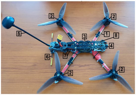
Figure 1.
7-inch FPV quadcopter with AL-based frame: 1—AL frame; 2—motors (2807, 1300 KV); 3—Flight Controller (FC) and Electronic Speed Controller (ESC); 4—camera; 5—video transmitter (VTX) antenna; 6—control link antenna (866 MHz); 7—VTX module; 8—CF top plate. The main dimensions are shown in Figure 2a.
As illustrated in Figure 1, only the lower frame section of the ALframe drone—responsible for carrying all mechanical loads and conducting heat from the motors—was made of AL. The second drone was assembled entirely on a commercial Mark 4 carbon fiber frame. In both cases, the upper frame section, typically used for battery mounting, was made of CF. Thus, the only structural difference between the two drones was in the lower frame section directly connected to the motors (Figure 2). The aluminum frame was 5 mm thick, cut from a single sheet without joints, whereas the CF frame was assembled from bolted sections, with the motors mounted on 5 mm thick arms. In top view, both frames had identical dimensions (Figure 2a).
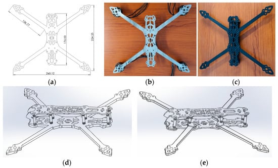
Figure 2.
Frame geometries: (a) basic dimensions of AL and CF frames (in mm); (b) AL frame; (c) commercial CF Mark 4 7-inch frame; (d) CAD model of frame with AL basic plate; (e) CAD model of frame with CF basic plate.
The AL frame material was produced using roller casting, followed by mechanical machining via waterjet cutting. The final masses of the experimental drones without battery were:
mAL = 577.2 g (with AL frame);
mCF = 540.0 g (with CF frame).
The mass difference results from the higher density of aluminum compared to carbon fiber. Both drones were powered by the same Li-ion 6S2P battery (mBAT = 880 g). The frame with the lower plate from aluminum alloy (Figure 2d) was cut from a 5-mm-thick sheet, weighing 180.17 g, while the CF frame (Figure 2e) weighed 121.40 g, including fasteners (more numerous in the CF frame). The bottom plates differed slightly in volume: 53,345.20 mm3 for the AL plate and 53,158.28 mm3 for the CF plate, the latter being thinner (3 mm) in the central region.
Payload selection. Preliminary flight tests were performed to characterise the lifting capability of the tested 7-inch configuration (motors, propellers, battery, and assembled airframe). These tests showed that a 2.0 kg mass (≈20 N) represented a practical upper bound for sustained hover and short-duration transport for this build; hence, the two experimental conditions reported in this study were 0 N (no payload) and 20 N (payload ≈2.0 kg). Selecting an unloaded and a near-maximum loaded condition allows the comparison of baseline and worst-case thermal and dynamic behaviour of the propulsion system, which is the objective of the present work. This two-point strategy (no-load vs. high-load) is commonly used in multirotor performance and thermal investigations to expose efficiency degradation, overheating, and dynamic instabilities that may not be observable under light loading [18,19].
The drone with the payload attached is shown in Figure 3 before take-off.
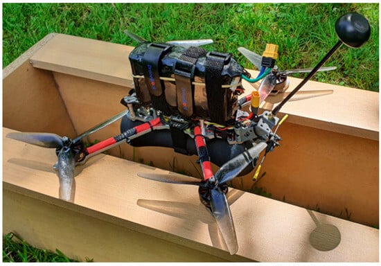
Figure 3.
ALframe drone with 20 N payload before take-off. The main dimensions are shown in Figure 2a.
Motor’s power consumption was evaluated using Betaflight Blackbox Explorer 3.7.0 software.
The test flight lasted 5 min in hover at an altitude of approximately 1 m above ground level. Immediately after the test, the drone landed, and infrared images were captured using a thermal imaging camera. Thermal images were captured using a Bosch Professional GTC 600 C infrared camera with a sensor resolution of 256 × 192 pixels. According to the manufacturer’s specifications, this resolution is standard for cameras of this class and does not affect the accuracy of temperature measurements (±2 °C or ±2% of the reading). The time between motor shutdown and image capture was 2–3 s. Thermal images were processed using GTC Transfer Software v. 1.7.2.0.
During the flights, log files were recorded, providing:
- -
- Motor load distribution;
- -
- Total electrical power drawn from the battery;
- -
- Gyroscope data for determining resonant frequencies of the drones along all three spatial axes.
The Power Spectral Density (PSD) of vibrations was computed from the gyroscope data using Fast Fourier-Transform (FFT) in Blackbox Explorer software. PSD analysis is widely used in UAV engineering to identify dominant vibration frequencies and assess system stability [20].
Each flight was repeated three times. After each flight, the drone was cooled for 30 min, during which the battery was recharged to its initial level. The maximum motor temperatures were as follows: variant CF 0 N—43.5 ± 3.1 °C, variant CF 20 N—86.3 ± 9.0 °C, variant AL 0 N—41.9 ± 3.0 °C, variant AL 20 N—54.7 ± 3.5 °C. Only the first flights from each series were used as an example for experimental and numerical analysis. Their log files was used to define the boundary conditions for FEM modeling.
For the estimation of heat power dissipation in motors, we used the following approach. The total electrical power drawn from the battery was determined from the log files as a tabular function of time :
The average values of are reported in Table 2, column ‘Power, W’. From this power, the ‘hotel load’ of the onboard electronics (FC, VTX, camera, etc.) must be subtracted. The simplest approach is to assume it as a constant PAV, measured on the ground with the electronics armed and the motors disarmed. Based on the initial segments of the power curves, PAV was estimated at ≈15 W for both drones:

Table 2.
Total battery power and per-motor energy distribution from log file analysis.
This power is considered to feed the propulsion system (ESC + motors). Such a separation of power and further identification of propulsion characteristics is recommended in works on experimental characterization of multirotor propulsion systems [21].
The log files also contain the fractional loads of individual motors (percentage throttle), the propulsion power is distributed proportionally:
The average values of were collected in Table 2 (columns “Motor 1”–“Motor 4”).
The heat power generated in the i-th motor is as follows:
where denotes the electro-mechanical efficiency of the motor. This parameter may also include ESC losses if the propulsion system is considered as a whole. In practice, is obtained from measured efficiency curves or loss models as a function of rotational speed and torque (or current), derived from dynamometer tests or simplified analytical models [22].
The motors load distribution and total power consumption data were used as input for FEM simulations of temperature distribution within the motors and frames. The FEM calculations were performed in SolidWorks 2024 by generating accurate geometric models of the test drones, applying boundary conditions derived from the log data, and solving the steady-state thermal conduction problem.
To enhance clarity of paper, the next figures in this manuscript are organized by drone configuration and flight condition. For each configuration (CF and AL), data are presented separately for unloaded (a) and loaded (b) flight conditions.
3. Results and Discussion
3.1. Experimental Results
The thermal imaging results are presented for the drone with a CF frame (Figure 4) and the drone with an AL frame (Figure 5). These images show both the maximum temperatures at the hottest points of the motors (stator region) and the overall surface temperature distribution across the drone.

Figure 4.
Thermal image of the CFframe drone after 5 min hover: (a) no payload (0 N), (b) with 20 N payload.
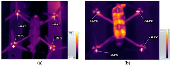
Figure 5.
Thermal image of the ALframe drone after 5 min hover: (a) no payload (0 N), (b) with 20 N payload.
Analysis of the temperature distribution after the 5-min hover test yielded the following observations.
No additional payload: The maximum motor temperatures in both drones were similar (Figure 4a and Figure 5a) and well below the manufacturer’s specified limit of 60 °C (FlashHobby A2807 datasheet). Under such conditions, the frame material had a negligible influence on the motor’s temperature.
With 20 N payload: The maximum motor temperature for the CFframe drone exceeded 90 °C (Figure 4b), indicating dangerous overheating. For the ALframe drone, maximum motor temperatures remained below 60 °C (Figure 5b), within the safe operating range.
These results indicate that replacing the CF frame with an AL frame of identical geometry reduced motor temperature by approximately 30 °C under extreme payload conditions.
Temperature differences between individual motors were also analyzed. For the CFframe drone, this difference reached 25 °C, whereas for the ALframe drone it was only 6–7 °C (Figure 4b and Figure 5b). This disparity is influenced by uneven motors loading—minimized as far as possible through careful payload and battery positioning related to the drone’s center of gravity—along with variations in motor and propeller characteristics.
Motor power consumption was evaluated using flight log files, which included percentage throttle values for each motor. An example dataset for the CFframe drone is shown in Figure 6 (first 20 s of flight), alongside total battery power consumption (Figure 7). Equivalent datasets for the ALframe drone are presented in Figure 8 and Figure 9. Figure 7, Figure 8 and Figure 9 present the total battery power consumption and the distribution of throttle values among the four motors for both frame configurations. For the CFframe drone (Figure 7), the total power draw increases sharply when the 20 N payload is applied, reaching values close to 775 W. In contrast, the ALframe drone (Figure 9) exhibits lower total power consumption under the same load (≈742 W), despite showing slightly higher consumption at no load. This reversal indicates that the CFframe motors lose efficiency under thermal stress, whereas the AL frame helps to maintain more stable operating conditions.
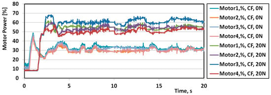
Figure 6.
Motor percentage power distribution (percentage throttle)in the first 20 s of CFframe drone flight, with payloads of 0 N and 20 N.
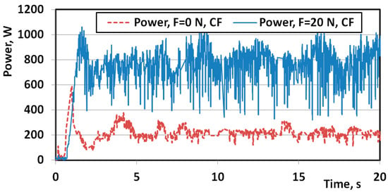
Figure 7.
Total battery power draw (CFframe drone), first 20 s, payloads of 0 N and 20 N.
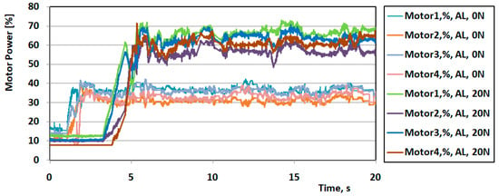
Figure 8.
Motor percentage power distribution (percentage throttle) in the first 20 s of ALframe drone flight, with payloads of 0 N and 20 N.
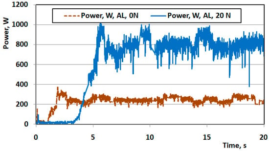
Figure 9.
Total battery power draw (ALframe drone), first 20 s, payloads of 0 N and 20 N.
A comparison of motor power distribution (Figure 6 and Figure 8) further highlights this effect. In the CFframe drone, throttle values deviate more strongly between individual motors, particularly with payload, which correlates with the larger temperature differences observed in thermal images (Figure 4). For the ALframe drone, throttle values remain more balanced across motors (Figure 8), consistent with the smaller temperature differences shown in Figure 5.
Overall, Figure 7, Figure 8 and Figure 9 demonstrate a clear link between thermal and electrical performance: the AL frame not only reduces overheating but also improves energy efficiency under payload. These results confirm that motor thermal conditions directly affect power consumption and that frame material selection can mitigate efficiency losses during high-load operation.
An important feature observed in Figure 7, Figure 8 and Figure 9 is the presence of significant short-term fluctuations in battery power draw, with amplitudes reaching up to 400 W. These oscillations are characteristic of FPV drones and result from the combined effects of flight controller corrections and pilot inputs during hover. In contrast to highly stabilized multirotor platforms, where fluctuations originate almost exclusively from the autopilot system, FPV drones rely to a large extent on the pilot to maintain position. Consequently, the control loop involves both the onboard controller and the pilot’s manual corrections, leading to rapid throttle variations and visible power fluctuations. While the instantaneous power draw oscillates strongly, the average consumption remains consistent with the applied payload, confirming the stability of the experimental conditions. This highlights the importance of evaluating frame thermal performance under thermally demanding missions.
The averaged power values and energy distribution across motors are calculated using Equations (1)–(4) and summarized in Table 2.
The condition of the power source was also monitored during the hover experiments. The drones were powered by a Li-ion pack consisting of 12 Samsung INR21700-40T cells (4000 mAh), connected in a 6S2P configuration. The maximum permissible continuous current for this configuration is 70 A. Analysis of the log files showed that the peak current during the 20 N payload test did not exceed 45 A. Over the course of a 5-min flight, the voltage of individual cells decreased from 4.1 V to 3.6 V, which remains well above the safe operational limit of 2.6 V per cell. These results indicate that the battery was not overloaded and that its health and service life were not adversely affected during the experiments.
Key findings from this analysis.
With no payload: The ALframe drone consumed more power (250.24 W) than the CFframe drone (213.74 W), likely due to the AL frame’s higher mass.
With 20 N payload: The ALframe drone consumed less power (741.78 W) than the CFframe drone (774.46 W). This reversal can be attributed to: 1. The frame mass difference becoming negligible compared to the total drone mass with payload. 2. Reduced motor efficiency in the CFframe drone due to overheating.
Vibration characteristics were assessed from the gyroscope data in the log files. Figure 10 shows the drone’s reference axes for oscillation measurement.
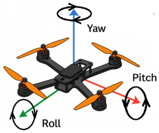
Figure 10.
Reference axes for vibration analysis.
Comparative PSD results. For the CF frame, the vibration spectrum (Figure 11a) reveals several distinct resonant peaks centered around 60 Hz, 120 Hz, and 180 Hz, which are indicative of structural resonances excited during hover. These frequencies suggest the presence of periodic oscillations likely amplified by the segmented and bolted construction of the carbon fiber frame. The multiple peaks point to complex dynamic behavior, where different components of the frame may be interacting mechanically in ways that reinforce certain vibration modes. In contrast, the AL frame (Figure 12a) exhibits a markedly simpler vibration profile, characterized by a single low-frequency peak below 20 Hz. This suggests a more stable and damp response, likely resulting from the monolithic design of the aluminum frame, which lacks joints and discontinuities that could act as sources of resonance. The absence of higher-frequency peaks implies that the AL frame better suppresses structural vibrations, contributing to improved flight stability and reduced mechanical stress on onboard components.
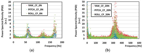
Figure 11.
PSD of vibrations for yaw, pitch, and roll (CF frame): (a) 0 N payload, (b) 20 N payload.
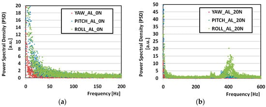
Figure 12.
PSD of vibrations for yaw, pitch, and roll (AL frame): (a) 0 N payload, (b) 20 N payload.
With 20 N payload the CFframe drone developed an additional strong peak around 320 Hz (Figure 11b), indicating undesirable dynamic loading. The ALframe drone exhibited a weaker high-frequency peak at ~400 Hz (Figure 12b).
The AL frame exhibited superior vibration performance, probably due to its monolithic structure and uniform thickness (Figure 2d), cut from a single aluminum sheet, in contrast to the CF frame’s assembled construction with variable thickness (Figure 2e). Due to the different geometric configurations, it is impossible to conclude the influence of the material on vibrations based on these data.
As follows from Table 1, the damping ratio for CF is 5–10 times higher than for AL. This is a fundamental material property that can significantly impact vibration attenuation. However, in the experiment, we observe lower vibrations for the frame made of AL. The only possible explanation for this, taking into account the close values of Young’s modulus (for CF 84 ± 7 GPa and for AL 81 ± 5 GPa), is associated with the difference in the geometry of the frames. Both frames have identical geometric dimensions on the arms to which the motors are attached. Since heat is dissipated precisely on the arms (this is shown by both the experiment and the calculation), this allows us to conclude the influence of the thermal conductivity of the material on the thermal mode of the motors. However, in the central part (Figure 2e), the CF frame is thinner, its thickness is 3 mm, and not 5 mm like the AL frame (Figure 2d). This smaller thickness in the central part of the CF frame is apparently the cause of greater vibrations.
It is important to note that the AL frame used in this study was monolithic, while the CF frame was assembled from bolted segments. This choice is largely determined by the manufacturing technologies available for the respective materials. For AL, the fabrication of a monolithic frame is technologically straightforward. In this study, the lower plate of frame was produced from roller-cast aluminum sheets and cut to shape using waterjet machining. The process enables efficient recycling of off-cuts back into the melt, resulting in essentially zero material waste. By contrast, CF composites require a fundamentally different production route. The standard industrial practice is to manufacture prefabricated, bolted frames, which reduces material waste and optimizes production costs. Consequently, all commercially available CF frames for FPV drones are prefabricated rather than monolithic. It should also be emphasized that the bolted connections in the CF frame do not influence thermal processes in the motors, since both experiments and FEM simulations confirmed that heat dissipation occurs primarily through the drone arms, which are monolithic in both designs. The prefabricated nature of the CF frame may, however, affect the drone’s mechanical and vibrational response.
Also important is environmental sensitivity of power and thermal performance. The flight tests in this study were performed at 28 °C and ~400 m a.s.l., but the observed trends should be interpreted in light of known environmental effects. Reduced air density at higher temperature/altitude increases the power required to generate a given thrust (propeller momentum theory; ISA-based analyses for UAVs) [23], while lower ambient temperatures enhance convective heat removal from motors and electronics. Additionally, elevated temperature can impair battery efficiency and shorten thermal headroom, further increasing power draw under load [24]. These mechanisms suggest that winter conditions would likely decrease motor temperatures and slightly reduce hover power at equal mass, whereas hot/high conditions would have the opposite effect; future studies will quantify these effects with controlled variations in temperature and altitude.
A summary of experimental analysis is collected in Table 3.

Table 3.
Summary of experimental results for CF and AL frames under 0 N and 20 N payload.
3.2. FEM Simulation
The primary motivation for creating a FEM model of thermal processes in the drone was to enable temperature prediction for the motors without direct measurements. This capability is particularly valuable during the design stage of UAV systems.
In the first step, CAD models of the studied drones were developed. For the CF frame variant, the Mark 4 frame geometry was obtained from an open-source model available on GrabCAD (Riley Entropy, GEPRC MARK 4 7-inch) (Figure 13a). The motor geometry (FlashHobby A2807, 1300 KV) was created based on manufacturer drawings (Figure 13b).
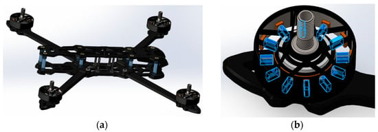
Figure 13.
CAD model of the frame with 2807 1300 kV motors: (a) complete frame with motors; (b) motor model with areas, where boundary conditions (Pheat)were applied.
Boundary conditions for the frame and motors were defined using data from log files, specifically the percentage distribution of motor loads and the total electrical power drawn from the battery (Table 2). These data were used as the basis for the heat source definition in the motors. Since only a portion of the electrical power is converted into heat, adjustments were necessary.
For small-scale motors, published models and experimental validations show that the operating efficiency η usually lies in the range 0.8–0.9 in the nominal operating region, and its drop under overload increases. In the FEM calculations, an average value of efficiency (0.85) was adopted. This approach is consistent with propulsion characterization methodologies and efficiency/thermal models for small drones presented in the literature [25]. Calculated Pheat values are provided in Table 4.

Table 4.
Calculated values of Pheat.
For the motors (type 2807 1300 KV) during hover, the convective heat transfer coefficient (HTC) is mainly driven by the propeller-induced downwash. Empirical data from a study under various flow conditions suggests that HTC values in this scenario fall within 40–100 W/m2K [26]. Considering propwash velocities typical for 7-inch propellers (≈8–12 m/s), a representative value of 60 W/m2K is selected for motor surfaces and 50 W/m2K for the arms. Also in the FEM simulations, thermal conductivity values were set to 7 W/mK for CF and 218 W/mK for the aluminum alloy.
Figure 14 and Figure 15 present the calculated results, allowing direct comparison with the experimental data in Figure 4 and Figure 5. The model reproduces the temperature distribution in the motors according to the power profiles from the log files. Calculated temperatures closely match the experimental values. However, some discrepancies remain. For the CFframe drone under 20 N payload, the maximum temperature predicted by FEM was 94.4 °C (Figure 14b), while the experimental thermal image showed 96.0 °C (Figure 4b). For the ALframe drone under the same conditions, the FEM prediction was 65.6 °C (Figure 15b), whereas the measured temperature was 59.7 °C (Figure 5b). These differences, although relatively small, illustrate the limitations of the simulation model in capturing all real-world variables, such as motor emissivity, airflow irregularities, and component-specific heat dissipation characteristics.
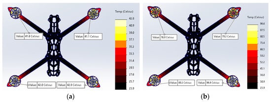
Figure 14.
FEM simulation of steady-state temperature distribution in the CF frame and motors for payloads of 0 N (a) and 20 N (b).
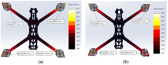
Figure 15.
FEM simulation of steady-state temperature distribution in the AL frame and motors for payloads of 0 N (a) and 20 N (b).
The observed in experiment reduction of approximately 30 °C in maximum motor temperature when using an AL frame instead of CF under a 20 N payload can be explained by the superior thermal conductivity of the aluminum alloy. Aluminum alloys exhibit thermal conductivities in the range of 130–226 W/mK, compared to only 5–20 W/mK for carbon fiber composites. This property allows the AL frame to function as an effective passive heat sink, dissipating heat away from the motor mounts into the arms. Consequently, both the maximum temperature and the temperature imbalance between motors were reduced (from ~25 °C for CF to ~6–7 °C for AL). The FEM simulations reproduced these effects, showing that the experimentally observed temperature distributions are consistent with the expected differences in thermal conductivity between the two materials. These results confirm that the AL frame provides significantly improved thermal management during high-load operation.
These arise from factors that are difficult or impossible to account for, such as individual motor characteristics, variations in the emissivity of motor and frame components, and the dependence of heat dissipation on motor operating conditions. Despite these limitations, the model provides sufficient accuracy for designing new drones or developing frames from alternative materials.
4. Conclusions
This study demonstrates, for the first time, a systematic comparison of carbon fiber and aluminum alloy frames in FPV drones under extreme payload conditions, combining experimental testing, thermal imaging, flight log analysis, and FEM simulations. The results show that aluminum frames, despite their higher density, reduce motor overheating by approximately 30 °C under maximum load, maintain more uniform temperature distribution between motors, and suppress unwanted resonant vibrations compared to carbon fiber frames. These findings confirm that frame material selection directly influences both thermal safety and dynamic stability in UAVs.
A second achievement of this work is the development and validation of an integrative methodology that links experimental thermal imaging with flight log data and FEM simulations. This approach enables predictive evaluation of UAV thermal behaviour during the design phase, reducing the need for repeated prototype testing.
Overall, the research highlights the dual role of frame materials in UAVs: providing structural strength and acting as passive heat sinks. The demonstrated methodology and findings provide practical guidelines for designing UAVs intended for defence, search-and-rescue, and other high-risk missions where both mechanical integrity and thermal reliability are critical. Future studies may extend this approach to hybrid or composite frames to balance weight and thermal performance.
Funding
This research was funded by the AGH University of Krakow, grant 16.16.110.663.
Data Availability Statement
The original contributions presented in this study are included in the article. Further inquiries can be directed to the corresponding author.
Acknowledgments
The author acknowledges the use of ChatGPT v.5 for improving the quality of the English text. The author has reviewed and edited the output and takes full responsibility for the content of this publication. The author thanks Marek Packo (AGH University, Kraków) for assistance with mechanical property testing, Anastasija Pigoreva for assistance during drone flight experiments, and Grzegorz Korpala (MiViA GmbH, Freiburg) for manufacturing the aluminum alloy drone frame.
Conflicts of Interest
The author declares no conflicts of interest.
Abbreviations
The following abbreviations are used in this manuscript:
| CF | Carbon fiber-reinforced polymer |
| AL | Aluminum alloy |
| FPV | First Person View |
| UAV | Unmanned Aerial Vehicles |
| FEM | Finite Element Method |
| SAR | Search-and-Rescue |
| FC | Flight Controller |
| ESC | Electronic Speed Controller |
| VTX | Video transmitter |
| HTC | Heat Transfer Coefficient |
References
- Hairi, S.M.F.B.S.; Saleh, S.J.M.B.M.; Ariffin, A.H.; Omar, Z.B. A Review on Composite Aerostructure Development for UAV Application. In Green Hybrid Composite in Engineering and Non-Engineering Applications; Khan, T., Jawaid, M., Eds.; Springer Nature: Singapore, 2023; pp. 137–157. [Google Scholar] [CrossRef]
- Sourav, B.; Raviraj, P.; Subash, D.; Gowtham, D.M. Surveillance and Inspection Micro Quadcopter Drone in Agriculture. Int. Res. J. Mod. Eng. Technol. Sci. 2023, 5, 2340–2348. [Google Scholar] [CrossRef]
- Zaluzhnyi, V.; Hryshchuk, R.; Ihor, S.; Oleksiy, H. The Armed Forces of Ukraine Unmanned Systems Future Development. Mil. Sci. 2024, 2, 5–16. [Google Scholar] [CrossRef]
- Aláez, D.; Prieto, M.; Villadangos, J.; Astrain, J.J. Towards a Heat-Resistant Tethered Micro-Aerial Vehicle for Structure Fire Sensing. Appl. Sci. 2025, 15, 2388. [Google Scholar] [CrossRef]
- Anand, S.; Mishra, A.K. High-Performance Materials Used for UAV Manufacturing: Classified Review. Int. J. All Res. Educ. Sci. Methods 2022, 7, 2811–2819. [Google Scholar]
- Sonmez, M.; Pelin, C.-E.; Pelin, G.; Rusu, B.; Stefan, A.; Stelescu, M.D.; Ignat, M.; Gurau, D.; Georgescu, M.; Nituica, M.; et al. Development, Testing, and Thermoforming of Thermoplastics Reinforced with Surface-Modified Aramid Fibers for Cover of Electronic Parts in Small Unmanned Aerial Vehicles Using 3D-Printed Molds. Polymers 2024, 16, 1536. [Google Scholar] [CrossRef] [PubMed]
- Milenin, A. The Impact of FPV Drone Frame Materials on Motor Thermal Conditions: Experimental and Numerical Analysis. In Proceedings of the KomPlasTech 2025, Krynica Zdrój, Poland, 2–5 March 2025; pp. 1–3. Available online: https://komplastech.agh.edu.pl/public_repo/2025/45.pdf (accessed on 16 August 2025).
- Klippstein, H.; Hassanin, H.; Diaz De Cerio Sanchez, A.; Zweiri, Y.; Seneviratne, L. Additive Manufacturing of Porous Structures for Unmanned Aerial Vehicles Applications. Adv. Eng. Mater. 2018, 20, 1800290. [Google Scholar] [CrossRef]
- Schleijpen, R.; van Binsbergen, S.; Geljon, M.; Meuken, D.; Deiana, D.; van Leeuwen, B. 30kW Laser Experiments against Drones. In Proceedings of the SPIE 11539, Emerging Technologies in Security and Defence III, Online, 21–24 September 2020; p. 115390A. [Google Scholar] [CrossRef]
- Fantuzzi, N.; Dib, A.; Babamohammadi, S.; Campigli, S.; Benedetti, D.; Agnelli, J. Mechanical Analysis of a Carbon Fibre Composite Woven Composite Laminate for Ultra-Light Applications in Aeronautics. Compos. Part C Open Access 2024, 14, 100447. [Google Scholar] [CrossRef]
- MatWeb. 6000 Series Aluminum Alloy—Thermal Properties. Available online: https://www.matweb.com/search/DataSheet.aspx?MatGUID=26d19f2d20654a489aefc0d9c247cebf (accessed on 16 August 2025).
- Rooy, A. Introduction to Aluminium and Aluminium Alloys. In ASM Handbook, Volume 2: Properties and Selection: Nonferrous Alloys and Special-Purpose Materials; ASM International: Materials Park, OH, USA, 1990; p. 1328. Available online: https://www.asminternational.org/results/-/journal_content/56/06182G/PUBLICATION/?srsltid=AfmBOoqC7PhvUKt_VmHwlkcqb3D5__28w9D6s94KXpDJFHxrSv7NK4P9 (accessed on 16 August 2025).
- Nasri, W.; Driss, Z.; Djebali, R.; Lee, K.Y.; Park, H.H.; Bezazi, A.; Reis, P.N. Thermal Study of Carbon-Fiber-Reinforced Polymer Composites Using Multiscale Modeling. Materials 2023, 16, 7233. [Google Scholar] [CrossRef] [PubMed]
- BVN, N.K.; Agrawal, A. Framework to Drone Part Selection, Verification and Fabrication of UAV for Multiple Applications. In Proceedings of the 2023 International Conference on Modeling, Simulation & Intelligent Computing (MoSICom), Chennai, India, 7–9 December 2023; pp. 105–110. [Google Scholar] [CrossRef]
- Zhang, X.; Liu, J.; Li, J.; Li, W.; Yuan, W.; Ma, Y.; Yao, Z. Progress of high-temperature superconducting composite materials for aerospace applications. Supercond. Sci. Technol. 2024, 37, 043001. [Google Scholar] [CrossRef]
- Lu, Y.; Wang, X.; Huang, Y.; Ma, Y.; Liu, Z.; Zhang, Y. Aerothermal effects on the thermal and structural responses of high-speed UAVs. Aerosp. Sci. Technol. 2024, 149, 109448. [Google Scholar] [CrossRef]
- Raza, M.; Tariq, M.; Abbas, S.M.; Alghamdi, H.; Alqarni, M.; Shafiq, M.; Ahmed, M.; Ali, H. Temperature measurement and monitoring for UAV-based systems using infrared thermography. Measurement 2025, 236, 117637. [Google Scholar] [CrossRef]
- Pätzold, F.; Bauknecht, A.; Schlerf, A.; Sotomayor Zakharov, D.; Bretschneider, L.; Lampert, A. Flight Experiments and Numerical Simulations for Investigating Multicopter Flow Field and Structure Deformation. Atmosphere 2023, 14, 1336. [Google Scholar] [CrossRef]
- Mohsan, S.A.H.; Othman, N.Q.H.; Li, Y.; Alsharif, M.H.; Khan, M.A. Unmanned aerial vehicles (UAVs): Practical aspects, applications, open challenges, security issues, and future trends. Intell. Serv. Robot. 2023, 16, 109–137. [Google Scholar] [CrossRef] [PubMed]
- Bendat, J.S.; Piersol, A.G. Random Data: Analysis and Measurement Procedures; John Wiley & Sons: Hoboken, NJ, USA, 2010; p. 613. [Google Scholar]
- Piljek, P.; Kotarski, D.; Krznar, M. Method for Characterization of a Multirotor UAV Electric Propulsion System. Appl. Sci. 2020, 10, 8229. [Google Scholar] [CrossRef]
- Saemi, F.; Benedict, M. Brushless DC Motor Sizing Algorithm for Small UAS Conceptual Designers. Aerospace 2024, 11, 649. [Google Scholar] [CrossRef]
- Pamula, G.; Ramachandran, A. Thermal Management for Unmanned Aerial Vehicle Payloads: Mechanisms, Systems, and Applications. Drones 2025, 9, 350. [Google Scholar] [CrossRef]
- El-Latif, E.I.A.; El-dosuky, M. Predicting power consumption of drones using explainable optimized mathematical and machine learning models. J. Supercomput. 2025, 81, 646. [Google Scholar] [CrossRef]
- Saemi, F.; Whitson, A.; Benedict, M. Heat Transfer Models and Measurements of Brushless DC Motors for Small UASs. Aerospace 2024, 11, 401. [Google Scholar] [CrossRef]
- Kang, J.; Lee, J.; Kim, H.J.; Nguyen, T.T.; Lee, J.; Song, Y.H.; Yoo, S.-J. Thermal Analysis of Outer Rotor BLDC Motor for Drone Considering Airflow Ventilation Cooling. IEEE Access 2025, 13, 128518–128531. [Google Scholar] [CrossRef]
Disclaimer/Publisher’s Note: The statements, opinions and data contained in all publications are solely those of the individual author(s) and contributor(s) and not of MDPI and/or the editor(s). MDPI and/or the editor(s) disclaim responsibility for any injury to people or property resulting from any ideas, methods, instructions or products referred to in the content. |
© 2025 by the author. Licensee MDPI, Basel, Switzerland. This article is an open access article distributed under the terms and conditions of the Creative Commons Attribution (CC BY) license (https://creativecommons.org/licenses/by/4.0/).