Abstract
Acid fracturing is an effective method of reservoir stimulation and has been widely used for carbonate reservoir development. However, knowledge on the propagation characteristics of acid-etched fracture is still poor due to the complexities of acidization and stress conditions, as well as the limitations of the fracture network reconstruction method, especially when dealing with large specimens. In this paper, a new method based on image-based 3D object reconstruction is proposed to study the fracture networks of specimens after acid fracturing by cutting rock specimens into thin slices, scanning them, and reconstructing 3D fracture networks. This method is more precise than the method of separating specimens into pieces and scanning, and it has advantages over the method of CT X-ray scanning when dealing with large specimens. Using this approach, the effects of natural fractures, stress conditions, and acid systems on the fracture propagation of specimens after true triaxial acid-fracturing tests were investigated. The fracture initiation and propagation patterns of specimens under different conditions were summarized. The results of the study show that the presence of a natural fracture will induce the propagation of fractures, in addition to demonstrating the positive effect of high horizontal stress difference on fracture initiation and provide an acid system conducive to the formation of a fracture network.
1. Introduction
In recent years, the high production of oil and gas in carbonate reservoirs has made them the focus of oil and gas exploration, development, and research. It is reported that approximately 70% of the world’s total oil and gas production comes from carbonate oil and gas reservoirs [1]. However, oil and gas are not easy to exploit in carbonate reservoirs because of their special properties. The internal structures of carbonate reservoirs vary greatly and can be classified into four main categories: matrix type, fracture type, sewing hole type, and large caves [2]. Carbonate reservoirs are also distinguished by their great heterogeneity, complex geological conditions, and the inherent difficulties associated with their development. In such cases, reservoir modification becomes a necessary step [3]. Currently, variations in reservoir characteristics can be effectively monitored and forecast in response to adjustments in oil-field operational parameters [4]. Technologically, the process of reservoir reforming typically employs fracturing techniques to artificially create a fracture network.
A substantial body of prior research has been conducted on the fracture propagation in hydraulic fracturing. The findings of the research studies conducted thus far indicate that the formation of a fracture network is possible when the pressure within the fracture exceeds the sum of the horizontal principal stresses and the tensile strength of the rock at the time of construction [5]. Another related study showed that natural fractures exert a pronounced influence on fracture propagation [6]. Wu et al. [7] conducted physical simulation experiments on pore-type carbonate reservoirs. The results demonstrated that when the horizontal stress difference is smaller, the hydraulic fracture deviates farther from the maximum horizontal principal stress. Additionally, with an increase in the horizontal stress difference, the hydraulic fracture propagates through the pore, and the fracture pressure decreases; this conclusion further reveals the influence of stress difference on hydraulic fracture. In the past decades, various carbonate reservoir reforming techniques associated with acid [8,9,10,11,12], including acidizing, acid fracturing, sand fracturing, and prepad acid fracturing, have been developed and reached a high level of maturity.
Early acid rock kinetic studies conducted by Lund et al. [13,14] utilized acid dissolution of calcite and dolomite to substantiate the theoretical applicability of acid pressure on carbonate reservoir dissolution. However, acid leakage from the wormholes was severe under the early process conditions; they were mostly plugged using acid-resistant pads [15,16]. Mukherjee et al. [17] proposed the method of using gel crosslinked with acid to increase the viscosity of acid to reduce the enlargement of the wormholes, which was demonstrated to be an effective approach in practice. In a series of indoor experiments, He et al. [18] configured a slow-release crosslinking acid with sand-carrying capacity. Li et al. [19] investigated the kinetic characteristics of acid–rock reaction and evaluated the acid-etched fracture conductivity of gelling acid. Wang et al. [20] investigated a high-temperature-resistant crosslinking agent. In combination with the evaluation of the construction effects in the field, the agent caused little damage to the soil layer; this series of studies demonstrated that gelling acids with higher viscosity can substantially enhance acidizing efficiency while minimizing losses. To enhance the flow rate of high-temperature and high-pressure acid-etched fractures, Wang et al. [21] employed numerical simulations and physical simulations with visualization, conducted finger-pressure experiments with different acids, and determined that 4–5-grade fracturing fluids and gelling agents are optimal. Alternating injection of acids and collodion fluid was employed by Zhao et al. [22] to investigate the impact of acid concentration, dosage, and reaction time on fracture propagation in sandstone. Their findings indicated that the complexity of fracture propagation exhibited a positive correlation with these parameters. Their research has significantly contributed to the advancement of construction technology. In a related study, Li et al. [23] proposed a compressibility evaluation system based on an analysis of the mechanical properties of the rock, proving the compressibility of carbonate rocks. Deng et al. [24] investigated the weakening effect of acid on the physical properties of carbonate rock and the destruction mode of the specimen after damage deterioration by rock mechanical property tests, hydrochloric acid-etching tests, and mineral microstructure analysis of carbonate rock specimens. Their findings demonstrated the positive role of the acid in the process. Zhang et al. employed gelling acid, crosslinking acid, and slip water as fracturing fluids and conducted fracturing tests on natural carbonate specimens, thereby confirming that fracturing with alternating acid injection can reduce the breakdown pressure [25]. Mou et al. [26] carried out acid fracturing for fractured carbonate rocks in the Tahe oilfield, and found that large amounts of SW injected before acid injection greatly improved the phenomenon of acid leakage during the construction process. The results of these studies demonstrate that the alternating injection process enhances fracture inflow efficiency and curtails working fluid leakage while sustaining the acid-etching effect. It has been proved that SW can also effectively reduce the filtration loss, but the effect of SW on the difficulty of rupture has not been paid much attention. Overall, these studies have not yet conducted a comprehensive investigation into the ground reaction characteristics of the acid system [27]. Additionally, the influence law of alternating injection of different viscosity acids and crosslinked acids on the fracture extension of carbonate rocks remains poorly understood.
Moreover, some scholars have investigated the law of fracture propagation and etching through the integration of two-dimensional or three-dimensional fracture propagation models with acid mass transfer reaction models [28,29], pointing out that the acid changes the elastoplastic characteristics of the fracture tip expansion zone. Chang et al. [30] investigated the impact of vertical stress difference coefficients on the propagation of shale fractures and observed that higher vertical stress difference coefficients impede the formation and propagation of hydraulic fractures. Hou et al. [31] carried out true triaxial physical modeling tests on cherts in northeast Sichuan and found that natural fractures had a large impact on the generation and propagation of fractures, and the fracture roughness near the well was greater than that at the distal end due to the action of the acid. In his 2022 study, Hou found that the fracture expansion rate in aacidized fractures near the hole end is higher than at the distal end, and the closer the hole is to the direction of fracture propagation, the more likely it is to make the fracture turn, thus forming multiple linked holes [32]. This conclusion reminds us to pay attention to the angle and distance between natural pores, holes, and the wellbore when setting research and construction plans. Liu et al. [33] postulated that the fracture strength in hydraulic fracturing is inversely proportional to the water pressure, in accordance with the principles of fracture mechanics. They observed that increasing water pressure resulted in an exacerbation of the propagation of branching fractures. Zeng et al. [34] conducted numerical simulations and found that hydraulic fractures are more likely to cross natural fractures, whereas acid fractures tend to be arrested due to the formation of wormholes. Consequently, excessively high acid concentration can impede fracture formation due to the enhanced formation of wormholes.
The above studies primarily illustrate the influence of differential horizontal stress difference and pumping pressure on fracture propagation, and there is also a preliminary conclusion that natural fractures can affect fracture propagation. However, the details of the influence of natural fractures on the propagation of new fractures is not clear enough.
Liu et al. [35] conducted hydraulic fracturing on coal rock and employed tomography in conjunction with the Avizo 2020 software for the reconstruction of fractures, and verified the applicability of the software’s fracture analyses. This demonstrated the efficacy of the software in fracture network reconstruction. Nevertheless, there is a paucity of applications of visual characterization of acid fracture for carbonate rocks, and a significant lack of results based on such means to study their fracture propagation laws.
In the present study, a series of acid fracturing tests under the true triaxial condition have been conducted on large carbonate specimens with complex natural fractures. To analyze the fracture propagation characteristics of specimens after acid fracturing, a novel method using image-based 3D reconstruction has been proposed. By using the new method, the fracture networks of tested specimens under different conditions, including different acid systems, different stress conditions, and different existing complex natural fractures were reconstructed. Fracture characteristics were investigated through 3D digital models to explore the effects of the natural fracture, stress condition, and acid system on the law of the propagation of acid fracture in this kind of rock.
2. Methodology
2.1. Experimental Equipment
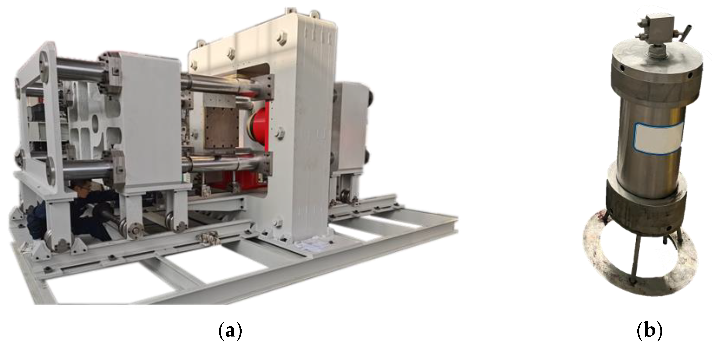
The experiment employed a large-scale true triaxial hydraulic fracturing test system manufactured by the Institute of Rock and Soil Mechanics, Chinese Academy of Sciences, Wuhan, China [30], as illustrated in Figure 1, which changed the traditional water injection fracturing into alternating multi-acid injection to realize the function of acid fracturing by adding a fluid conversion device; and the maximum output pump pressure of the experimental system was 140 MPa, with a resolution of 0.05 MPa. The displacement sensor had a resolution of 0.08 mm; the maximum volume of fluid injected in a single pumping was 800 mL; the triaxial loading unit could provide a maximum pressure of 85 MPa in one direction; and an acid-resistant stainless steel SUS316 manufactured by Chuangrong Petroleum Instrument Factory, Hai’an, China was used as a container for the fracturing fluid during the experiment, with a maximum volume of 800 mL.

Figure 1.
(a) Triaxial stress loading system; (b) fluid conversion device.
2.2. Specimen Preparation
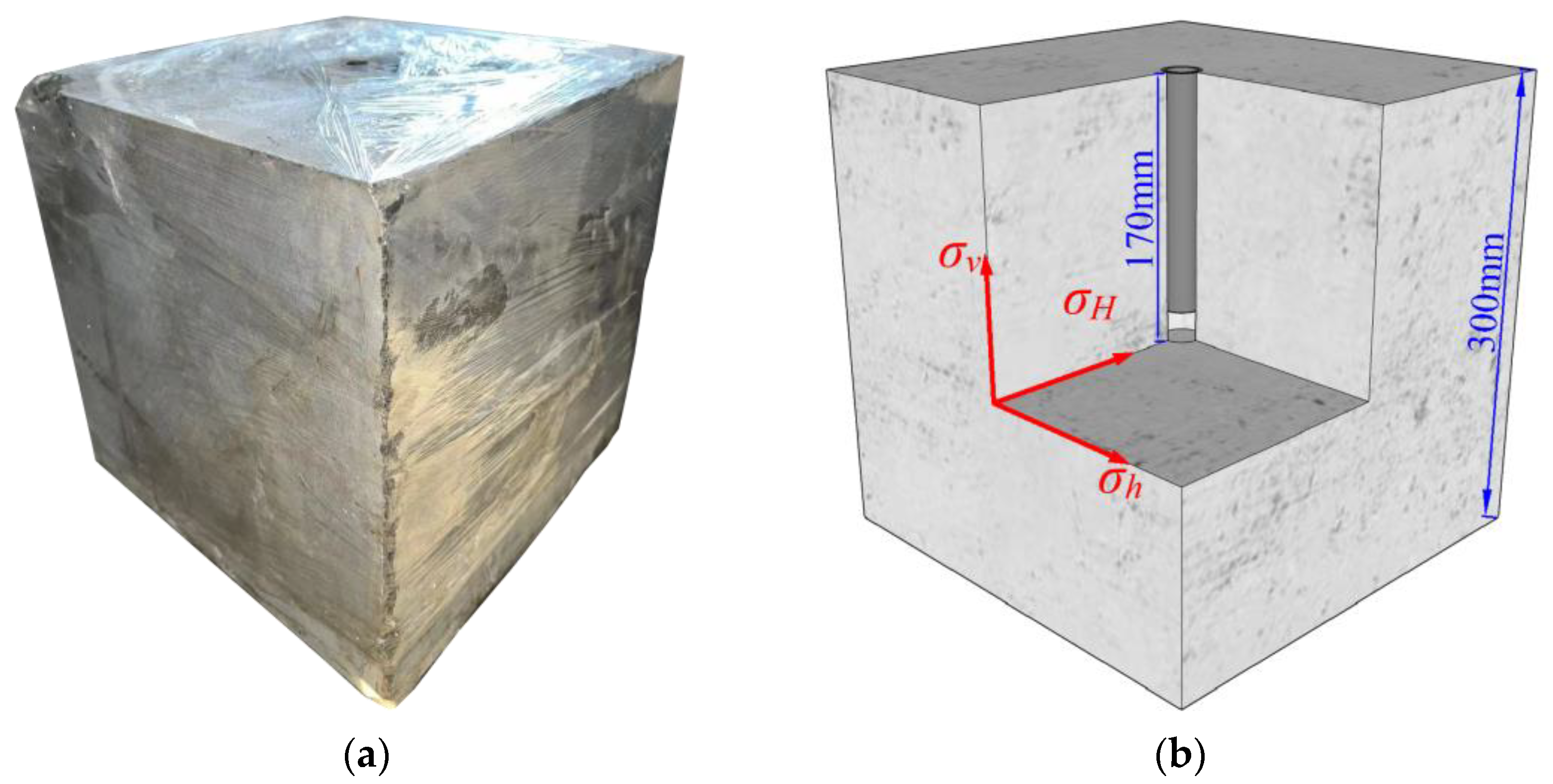
Carbonate rock from the Ordovician Majiagou Formation was collected for the acid fracturing test. As shown in Figure 2a, the specimens were derived from natural outcrops and underwent processing and cutting into seven cubic specimens with side lengths of 300 mm × 300 mm × 300 mm. In this study, eight specimens, designated as Z-1, Z-2, Z-3, Z-4, Z-5, Z-6, Z-7, and Z-8 were prepared. As shown in Figure 2b, a circular hole with a depth of 170 mm and a diameter of 25 mm was drilled on one side of the specimen. A 150 mm rebar pipe was placed and fixed with epoxy resin to simulate the wellbore. Additionally, 20 mm was reserved at the bottom of the well, designated as the bare well. The specimens were wrapped tightly with cling film to prevent corrosion of the apparatus by acid leakage after fracturing.
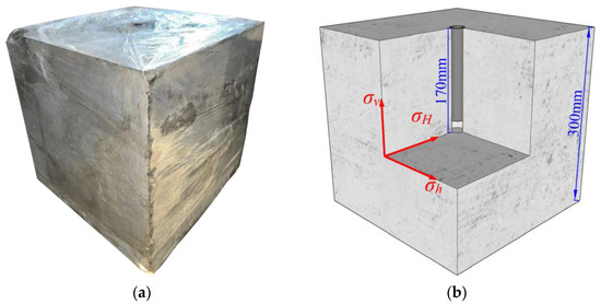
Figure 2.
(a) Carbonate rock specimens with the wellbore drilled; (b) schematic diagram of stress condition.
The above specimens developed natural fractures; the orientation of the fractures, are clearly summarized in Table 1.

Table 1.
Natural fracture development in different carbonate rock specimens.
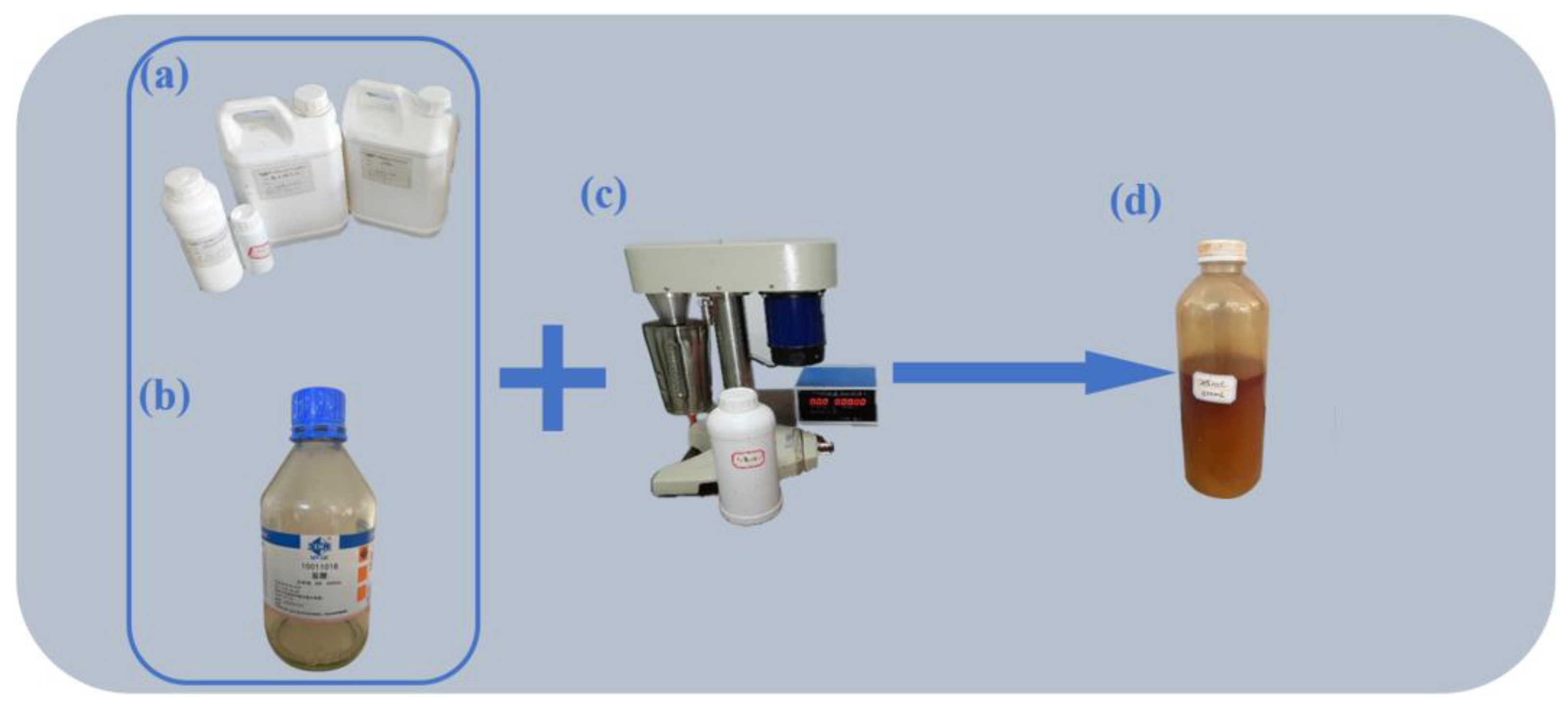
As Table 2 shows, the same formulations of LVA, HVA, and CLA that have been previously employed in field studies were utilized in this experiment. The configuration steps are shown in Figure 3. Initially, the concentrated hydrochloric acid was diluted to a 20% mass fraction, and a range of additional substances, including corrosion inhibitors, iron ion stabilizers, discharge aids, thickeners, and so forth, were introduced under low-speed stirring (below 300 rpm). These were then stirred at 1200 rpm in a specialized high-speed mixer, to which a red dye was added to facilitate the identification of the fracture path during the acid fracturing process.
Table 2.
Fluid composition.
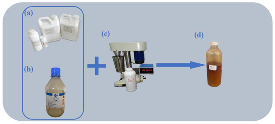
Figure 3.
Manufacturing of acid liquid used for acid fracturing tests: (a) additive; (b) 36–38% concentration hydrochloric acid; (c) stirring device; (d) configuration of complete acid liquid.
2.3. Experimental Scheme
In consideration of the ground stress conditions at the site, a variety of loading stresses and acid types were established for the specimens (Table 3). The discharge rate was set to 6 mL/min.
Table 3.
Experimental scheme of acid fracturing considering different types of acid systems and stress conditions.
2.4. Experimental Methods and Procedures
The experimental process is shown in Figure 4, with specific details as follows.
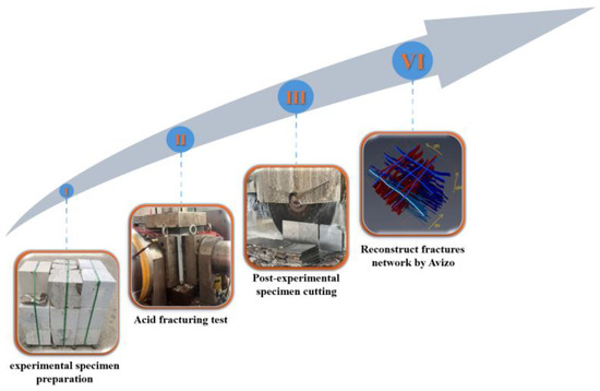
Figure 4.
Experiment flow chart.
- (1)
- The four walls of the pressure chamber were uniformly coated with oil, and the encapsulated cubic specimen was loaded into the pressure chamber. The specimen was then covered with a force transfer plate and the necessary piping was connected. In accordance with the experimental scheme, the working fluid was loaded into the fluid conversion device.
- (2)
- The triaxial stress loading system was activated and the piston elongation was adjusted to ensure that the hydraulic cylinder indenter was aligned with the surface of the specimen. The three-way stress (σv–σH–σh) was loaded to the target value at a rate of 0.5 MPa/s.
- (3)
- Subsequent to the stabilization of the stress, the initiation of the pumping procedure was conducted at a rate of 6 mL/min. If a sudden decline in the pumping curve was observed, accompanied by the efflux of acid from the surface of the specimen, this served as definitive proof that the specimen had undergone complete fracturing, and the pumping could be terminated. A minimum of 5 min was allowed for the acid to react with the fracture surface after terminating the pump.
- (4)
- Upon completion of the experiment, the pressurized chamber was opened to lift out the specimen and pay attention to the leaked acid. Following the removal of the specimen, the apparatus was cleaned and the related wastewater waste disposed of in an appropriate manner.
3. Avizo 3D Reconstruction Method
At present, two common and mature means for characterizing internal fractures in rocks are in use. The first method employs tools such as hammers and wedges to fracture the specimen along the rupture surface after the experiment. The exposed fracture surfaces are then marked, and subsequently the fracture surfaces are scanned using either a handheld or stationary three-dimensional scanner. Following repeated scanning, the fracture surfaces are reconstructed and then spliced into the model using software [35]. Alternatively, the specimen can be scanned using CT and reconstructed using slice data to obtain the morphology of the fracture. The initial method is rapid and effective in obtaining the morphology and structure of the fracture, but the capacity to extract the area, length, and width of the fracture is insufficient. The second method is frequently employed in the analysis of small-size specimens, exhibiting enhanced scanning efficacy. However, the penetration capacity of a conventional CT scanner is questionable for specimens with a side length of 300 mm. Moreover, the CT scanning outcomes are more intricate, and some scholars have utilized tomography in conjunction with other techniques. Reconstruction of the hydraulic fracture structure of coal rock using Avizo is feasible; however, in acidic fracturing specimens of carbonate rock, the presence of a considerable number of natural microfractures and acid-etching channels poses a challenge to the accurate determination of the target fracture.
Based on previous studies, this paper proposes a new method: Using a saw blade to cut the specimen, and subsequently extracting the fracture parameters from each layer of the cut surface. Following this, extracting the image of the cut. A reconstruction is then conducted using the Avizo software. The method not only completes the reconstruction of the three-dimensional structure of the fracture, but also extracts the specific parameters of the fracture. The specific procedure according to the example is as follows.
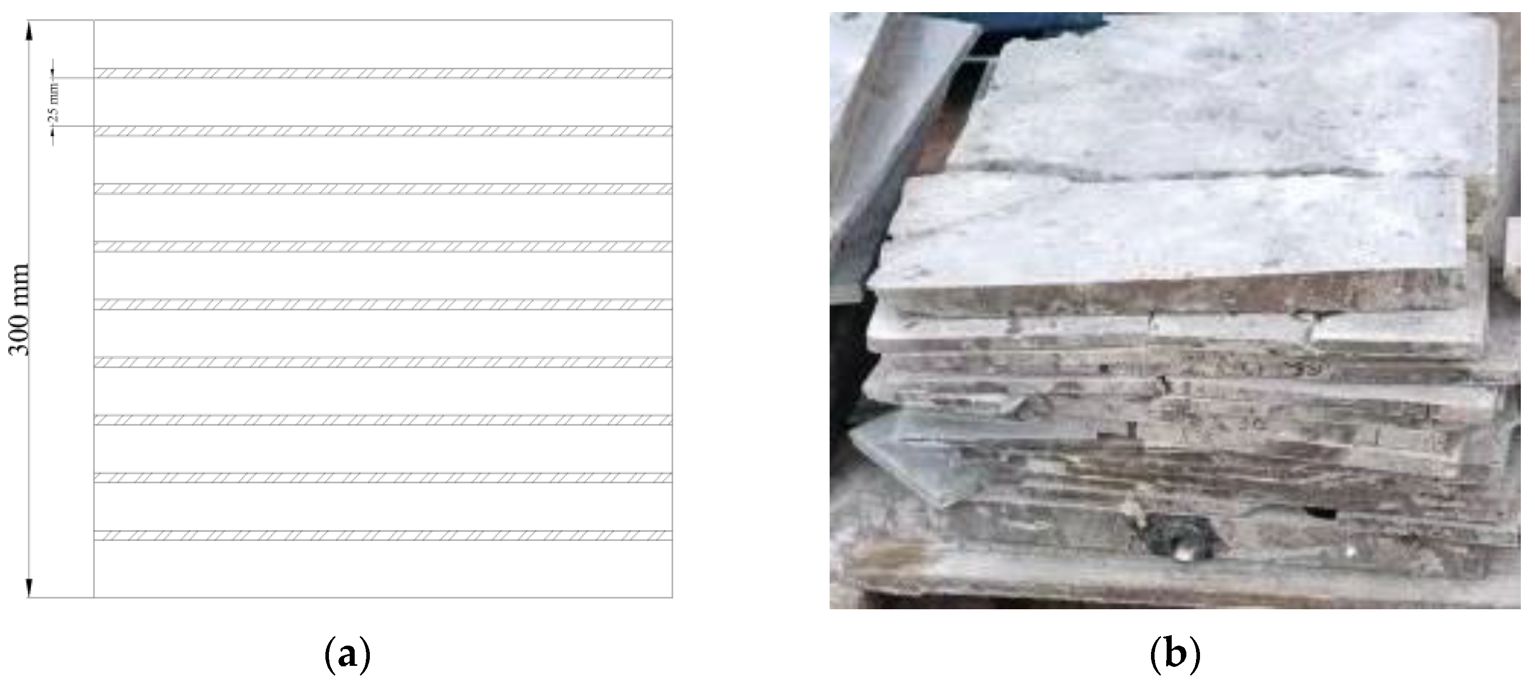
Firstly, the cling film should be removed from the surface of the specimen, the specimen should be cleaned, and a high-speed cutting machine should be used to cut the specimen layer by layer in the direction of intersection with the fracture surface at a large angle and with a thickness of 25 mm for each layer. A camera should then be used to take a front view of the cut surface for each layer. The resulting image is shown in Figure 5.

Figure 5.
(a) Cutting schematic; (b) slices cut from the carbonate rock specimens.
Crop the specimen section from the captured image, use the image processing software to convert the image type and check the image quality. Once this has been performed, the image should be named and saved according to the cutting order.
The fracture reconstruction process is illustrated in Figure 6. All section pictures of Z-1 should be imported into the Avizo software. The import method should be set to “Luminance”, voxels should be selected for import, the width of the X- and Y-directions should be set to 1, and the width of the Z-direction should be set to 1. The width of the Z-direction is calculated using the following formula: (1000 pixels)/(number of slices). The width in the Z-direction is calculated by the following formula: pixels corresponding to (300/number of slices). Subsequently, the “1-.am” file is split using the “Interactive Thresholding” command, resulting in the generation of the “1-thresholded.am” file. The “1-thresholded.am” file is then subjected to the “Remove small spots” command, which is used to remove small noise spots, thereby generating the “1-thresholded.filter” file. The “Segmentation” command in the “Segmentation” column should then be employed to manually modify the areas that are not correctly recognized using the lasso, brush, and other tools. Once this is complete, the “Volume Rendering” command should be used to render the model.
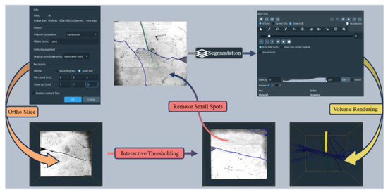
Figure 6.
Workflow on reconfiguration of three-dimensional fractures through Avizo software.
4. Experimental Results
The research focuses on deep carbonate rock formations with a thickness greater than 3000 m. The presence of outcrop rocks with representative fracture structures at this depth is limited, and the fracture development of carbonate rock is intricate. In contrast to shale, sandstone, and similar formations, obtaining samples with precise geometrical morphology presents a significant challenge. Therefore, when devising the experimental plan, we ensured that the specimens exhibited similar fracture conditions and that the number of specimens was sufficient to obtain results by two-by-two comparison. The results were obtained by two-by-two comparison.
So, eight sets of true triaxial fracturing experiments were conducted in this paper. The effects of different factors on acid fracture were investigated through the reconstruction results of the specimens after fracturing. A comparison of the fracture morphology of the water and acid groups, shown in Table 4, revealed that the breakdown pressure of the acid group and specimens with natural fractures was typically lower, and in some cases, the acid fracture merged with the natural fracture. This aligns with the observations made by Wu et al. [7]. Moreover, the experiment revealed that the fluid leakage of specimens Z-5 and Z-6, which were treated with HVA, was significantly reduced in comparison to specimens Z-3 and Z-8, which were not treated with HVA. This finding aligns with the observations made by Mou et al. [26].
Table 4.
The formation breakdown pressure of different carbonate rock specimens.
4.1. Fracture Structure and Morphology
4.1.1. Fracture Structure
Once the experiments had been completed and post-processing had been conducted in accordance with the prescribed experimental steps outlined in Section 3, the three-dimensional fracture distribution model for each specimen could be generated. This is illustrated in Figure 7, Figure 8, Figure 9, Figure 10, Figure 11, Figure 12, Figure 13 and Figure 14.
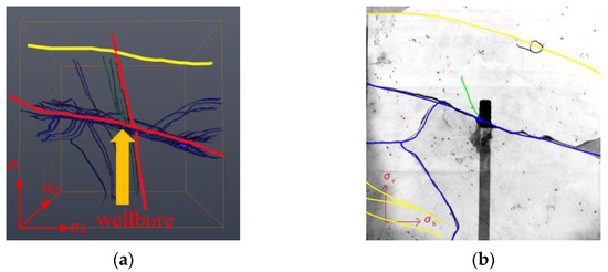
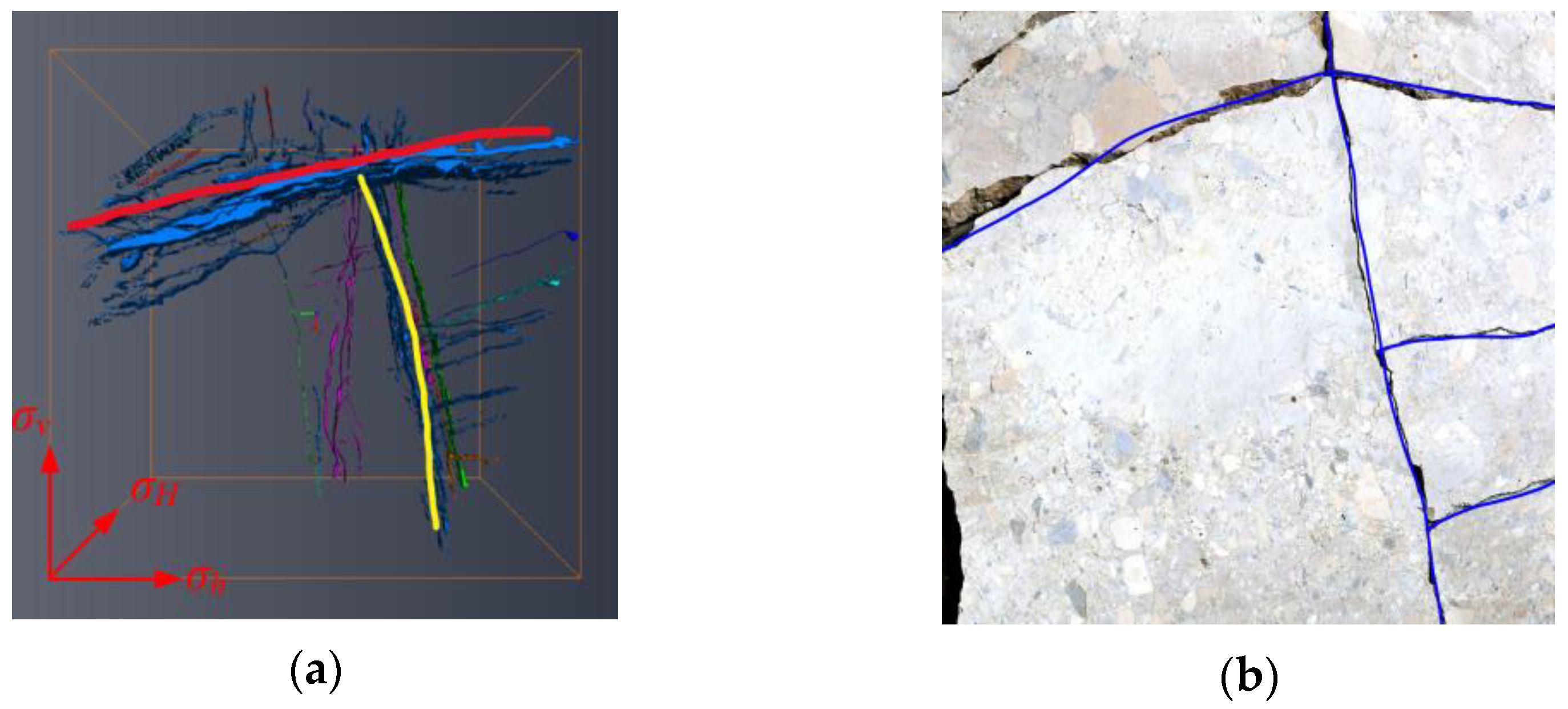
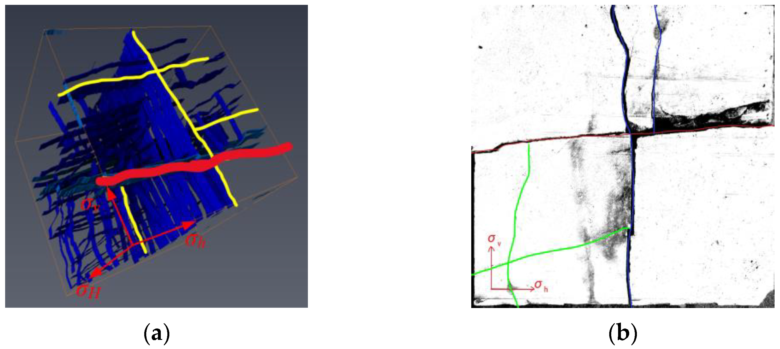
Figure 7.
(a) Spatial distribution of three-dimensional fractures in Z-1 specimen; (b) cut slice.
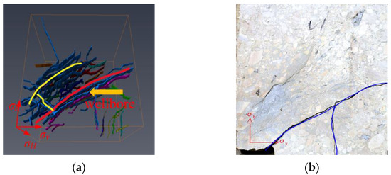
Figure 8.
(a) Spatial distribution of three-dimensional fractures in Z-2 specimen; (b) cut slice.
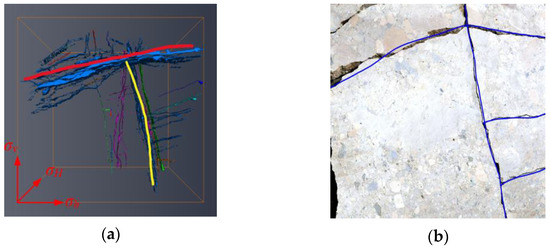
Figure 9.
(a) Spatial distribution of three-dimensional fractures in Z-3 specimen; (b) cut slice.
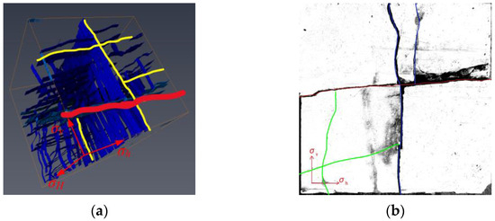
Figure 10.
(a) Spatial distribution of three-dimensional fractures in Z-4 specimen; (b) cut slice.

Figure 11.
(a) Spatial distribution of three-dimensional fractures in Z-5 specimen; (b) cut slice.
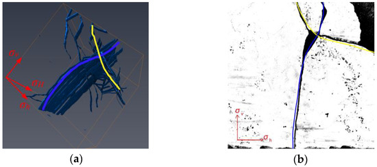
Figure 12.
(a) Spatial distribution of three-dimensional fractures in Z-6 specimen; (b) cut slice.
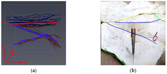
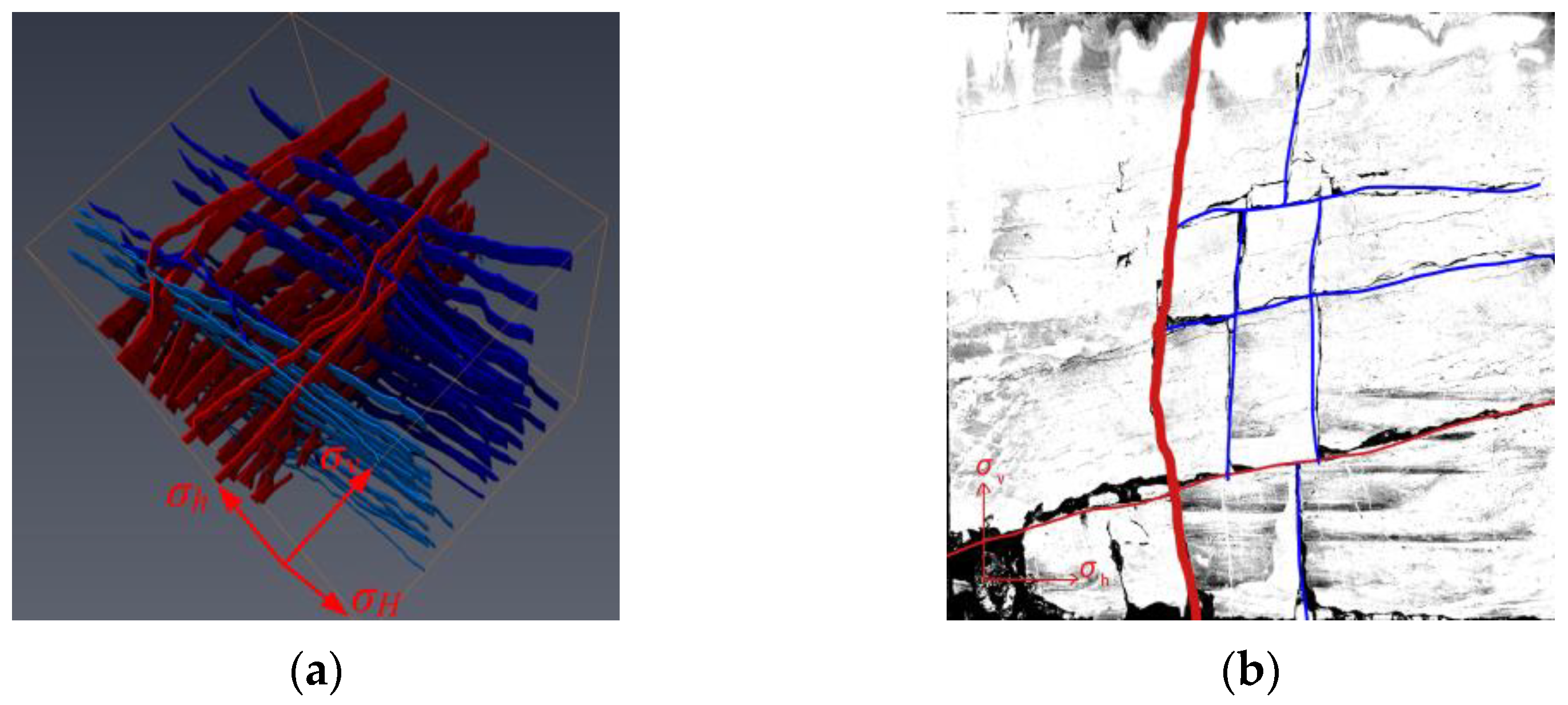
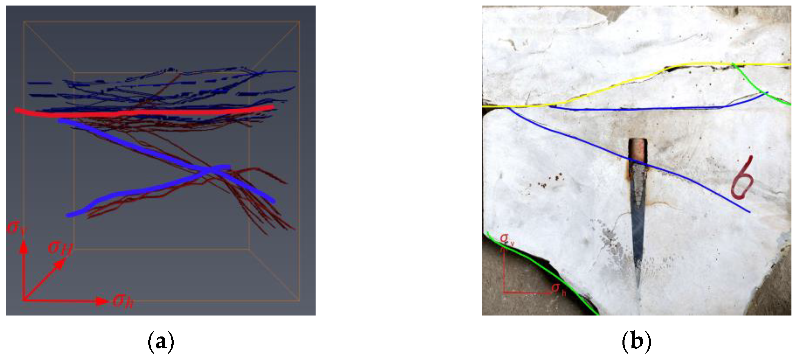
Figure 13.
(a) Spatial distribution of three-dimensional fractures in Z-7 specimen; (b) cut slice.
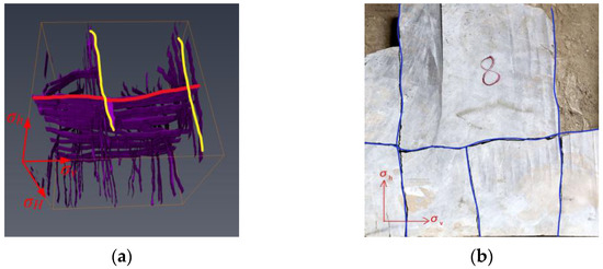
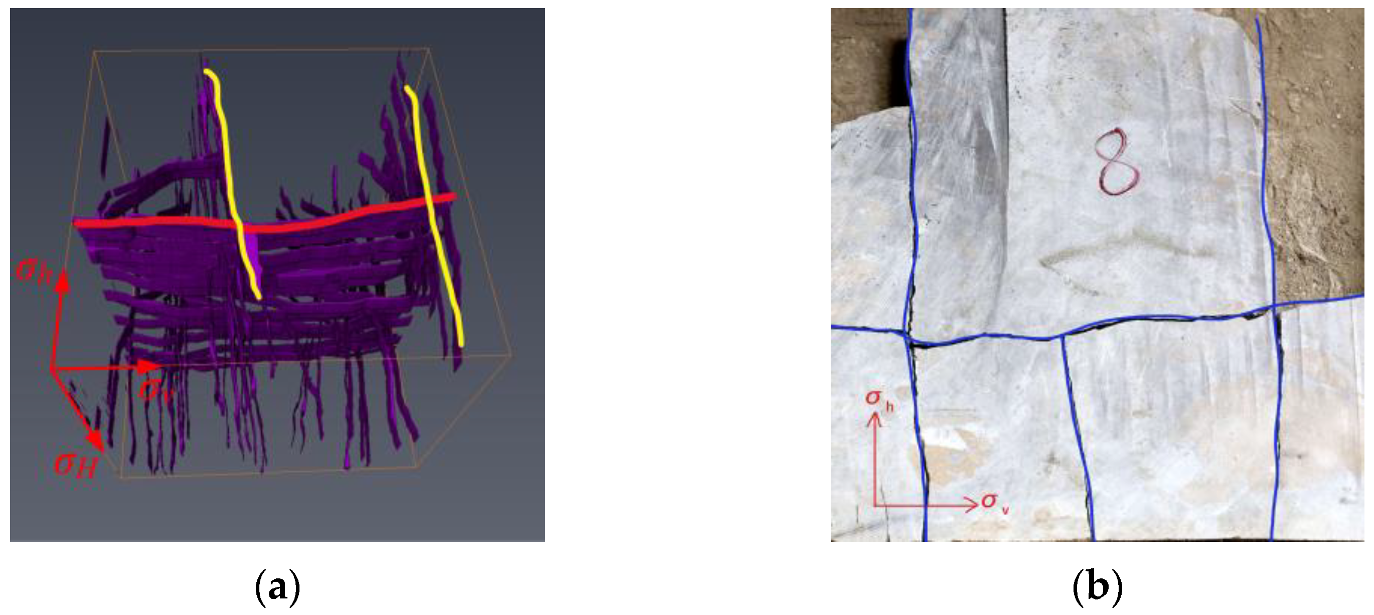
Figure 14.
(a) Spatial distribution of three-dimensional fractures in Z-8 specimen; (b) cut slice.
As shown in Figure 7, the new acid-etched fracture (red line) of specimen Z-1 generated by fracturing is close to perpendicular to the σH–σv plane, and when it extends outward, it communicates with the natural fracture (yellow line) and forms a certain angle. The fracture network near the wellbore is relatively complex, and the fracture is relatively simple when it reaches the specimen surface. This result aligns with Hou’s experimental findings [31]; however, it differs in that the microfracture inside Z-1 has been penetrated, resulting in steering within a portion of the fracture.
According to Figure 8, the direction of the primary fracture of specimen Z-2 is at an angle of about 30° to the σH–σv plane, and the secondary fracture is mainly formed by many tiny natural fissures in the interior that are interconnected. The width of the fracture near the level where the wellbore is located is obviously larger than that of others. There are some cases that differ from the results of Xi’s study [6], where microfractures within the rock mass have less impact on hydraulic fracturing cracks, but more impact on acid fracture production.
As can be seen from Figure 11 and Figure 12, for the specimens with the same acid system (Z-5, Z-6), despite the different number of natural fractures, the acid fractures also penetrate the natural fractures, which is more similar to the experimental results of Deng [24], with the difference that the deflection of the Z-6 cracks is more influenced by the joints in the rock, and the cracks are not flat and straight.
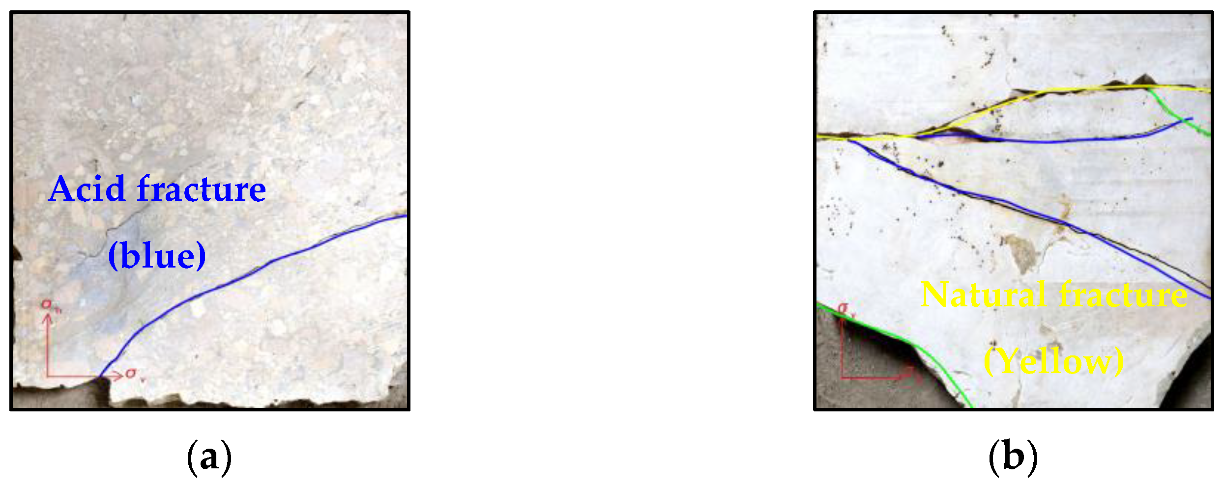
Comparing Z-7 and Z-8, which used HVA and LVA systems, respectively, in Figure 13, the Z-7 specimen shows that the acid-induced fractures (red lines) are mostly connected to the natural fractures (blue lines). The main fracture intersects the σH–σv plane at an angle of approximately 30°, with branch fractures forming at smaller angles (20–30°). In contrast, specimen Z-8 generates a set of parallel hydraulic fractures (yellow lines) that are parallel to the σH–σv plane; during fracturing, the slow flow of HVA introduces the possibility of fracture deflection [31].
A comparison of the reconstruction models reveals that the Z-7 wellbore, which was treated with a combination of HVA and crosslinking acid, forms an acid fracturing primary fracture with multiple secondary fractures in the vicinity of the wellbore. Additionally, the fracturing primary fracture gives rise to a complex fracture network that interacts with the natural fracture. The Z-1 wellbore, pumped with HVA, forms a fracturing primary fracture with a secondary fracture, which intersects with the natural fracture. In contrast, specimen Z-3, injected with water (Figure 9), forms only a main fracture that intersects with the natural fracture. In conclusion, the degree of fracture complexity is greater for the HVA + CLA than for the single HVA, which is greater than for SW.
As illustrated in Figure 10, Figure 11 and Figure 13, a comparative analysis of Z-4, Z-7, and Z-5 reveals that the latter exhibits a greater number of connections between acid-induced fractures and natural fractures, resulting in the formation of more extensive and wider fractures. Furthermore, when the angle between acid fractures and natural fractures is considerable, the acid fractures tend to traverse the natural fractures (as observed in Z-4 in Figure 9), whereas at smaller angles, the acid (blue) and natural fractures (red and yellow) converge (as observed in Z-8 in Figure 14).
As illustrated in Figure 15, for two groups of specimens using the same acid system (Z-2, Z-7), as demonstrated in the previous comparison, as the difference between σh and σH increases, the fracture length increases, but the development direction is more consistent. The large angles of the secondary fractures extend less from the main fractures, generally tending to be parallel to the development of the σH, and the width of the fracture is larger.
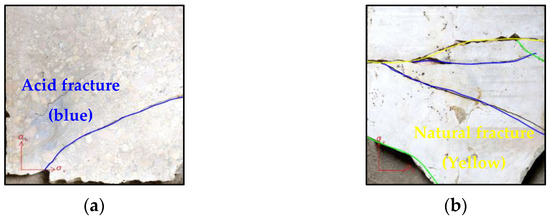
Figure 15.
Comparison of fractures under different horizontal stress difference: (a) 3 MPa; (b) 15 MPa.
4.1.2. Fracture Morphology
Based on the analysis of the previous results, the following fracture parameters were obtained.
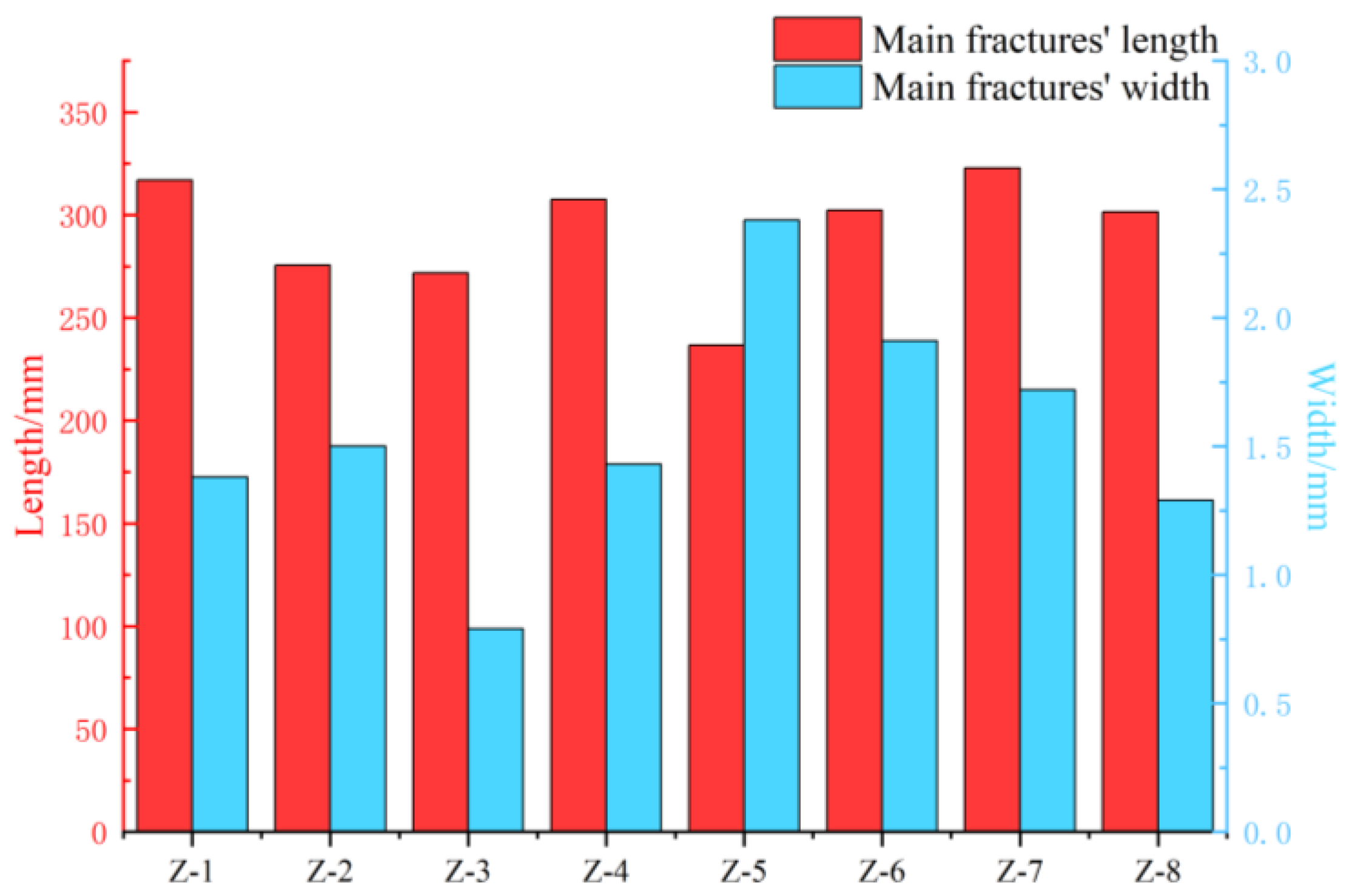
The results in Table 5 indicate that SW fracturing exhibits a higher breakdown pressure, a shorter main fracture length, and an enhanced communication effect with natural fractures. As illustrated in Figure 16, the transverse comparison of the main fracture widths reveals that the combination of SW, HVA, and CLA exhibits the widest width, while SW fracturing demonstrates the narrowest. This suggests that a multi-acid combination exerts a more pronounced effect on the fracture surface, with the width of the fracture under the influence of acid being markedly larger than that observed in SW fracturing.
Table 5.
Parameters of fractures in different carbonate rock specimens.
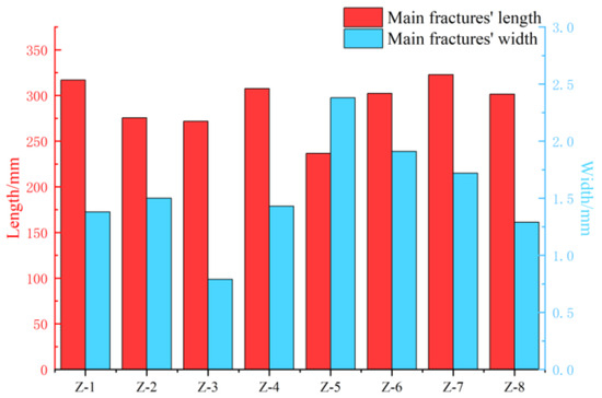
Figure 16.
Length and width of fractures in eight different carbonate rock specimens.
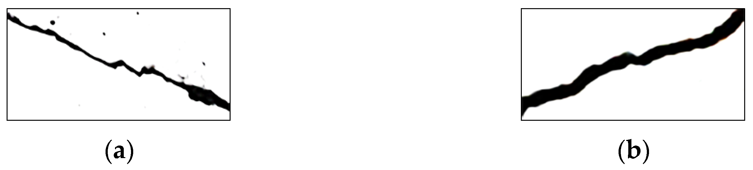
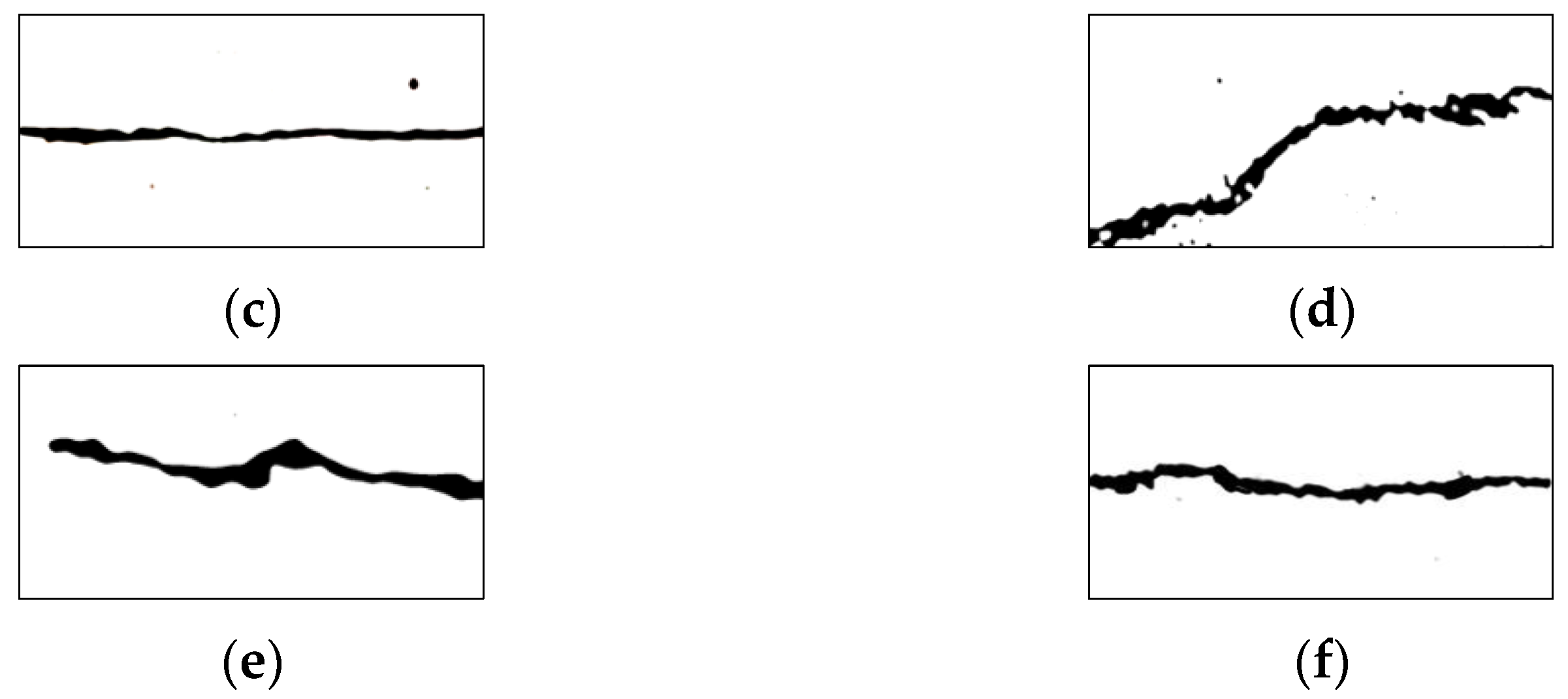
The effect of acid corrosion on the surface of selected specimens should be observed, and the fractal dimension of the typical fracture area, as shown in Figure 17, should be calculated.

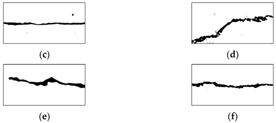
Figure 17.
Varying acid corrosion effects on fractures of different specimens: (a) Z-1; (b) Z-2; (c) Z-3; (d) Z-5; (e) Z-7; (f) Z-8.
The magnitude of the fractal dimension represents the roughness of the fracture and also reflects the acid-etching effect. Based on the calculated data in Table 6, a comparison of each specimen with Z-3, which uses water as the fracturing fluid, reveals that the acid-etching effect of the Z-5 specimen, which uses SW, CLA, and HVA under conditions of high horizontal stress difference, is the most significant. The acid-etching effect of the Z-2 specimen, which is injected alternately, is higher than that of the Z-1 specimen. Furthermore, the effect of the Z-7 specimen, which uses HVA, is higher than that of the Z-8 specimen, which uses LVA.
Table 6.
Fractal dimension of fractures in eight different carbonate rock specimens.
4.2. Fracture Complexity
In accordance with the tenets of topological structure, the alterations in topological parameters are independent of spatial transformations [36]. Li et al. [37] leveraged this attribute to enumerate parameters such as the number of intersections of each fracture type in space and the density of fracture, and to compute the comprehensive evaluation index of the fracture network after balancing the weights. This scholar’s methodology was employed to calculate the fracture complexity before and after the experiment in accordance with the experimental results.
Firstly, the nodes in space are classified into three types: Type I nodes, which are isolated endpoints at both ends; type X nodes, which are intersections of two intersecting fractures; and type Y nodes, which are intersections of fractures in a dinky cross. In the fracture network, each fracture must have a starting point and an end point, and such points can be of type I and type Y. Therefore, the number of fractures can be expressed as follows [37]:
: the number of fractures; : the number of type I nodes; : the number of type Y nodes.
Type X and type Y nodes can serve as connection points, and each X and Y node belongs to two fractures. The average connection point number for fractures can be calculated as
Substituting Equation (2) into Equation (3) gives
Before the experiment, specimens with natural fractures consisting only of type I nodes had a value of 0. Using experimental data, the calculated values are shown in Table 7 below.
Table 7.
Fracture complexity of each specimen.
A comparison of the number of nodes in the natural fracture and the increase in the number of nodes after the experiment allows for an evaluation of the change in the complexity of each specimen. The absolute value of the complexity of Z-5 with crossed natural fractures is the largest, indicating the greatest change in complexity. The greatest change in complexity was observed for Z-6, which utilized SW, CLA, and HVA. In contrast, the lowest-complexity fracture was observed for Z-3, which employed SW and exhibited the smallest increase in complexity post-experiment.
The impact of an acid system can be observed in the results of the comparison of the fracture network capacity (i.e., fracture complexity) and fracturing effect (i.e., fracture morphology) in Section 4.1.1 and Section 4.1.2, which indicate that the combination of SW, HVA, and CLA is the most effective, followed by HVA and CLA, and HVA, and finally SW demonstrates the least favorable outcome.
4.3. Treatment Pressure Curve
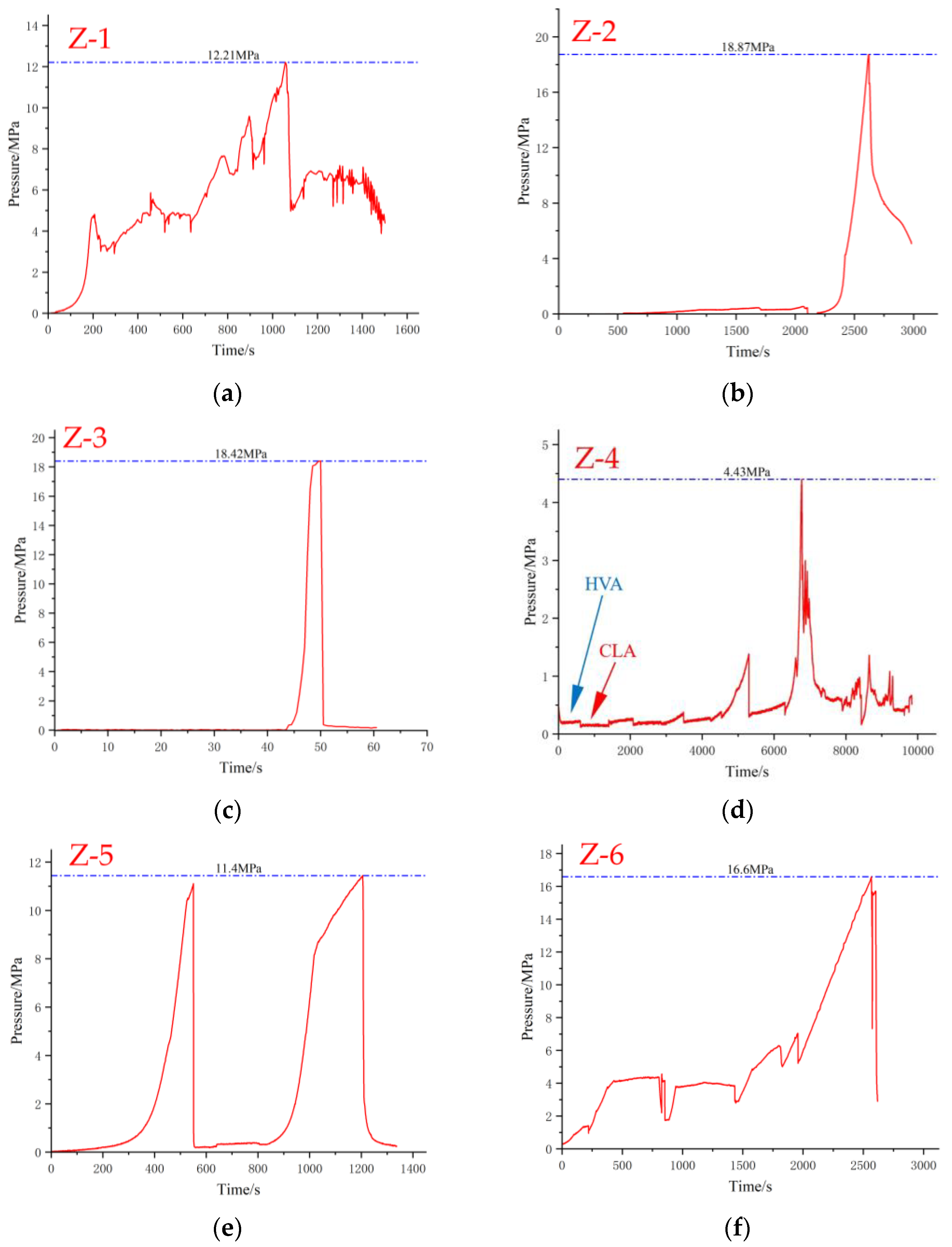
As shown in Figure 18, an analysis of the treatment pressure curves reveals that the curves of certain specimens treated with an acid solution exhibit a more pronounced zigzag pattern, indicating the presence of numerous internal small fractures that are susceptible to communication during fracturing. A comparison of the curves for specimens Z-1 and Z-2 demonstrates that the break of the specimen can be slowed down, and the duration of acid dissolution can be enhanced by increasing the injection of crosslinked acid. The curves of Z-2 and Z-4 demonstrate that an increase in the geostress difference facilitates the opening of internal fractures in the specimen, resulting in a more complex and variable acid flow path. A comparison of Z-5 and Z-6, which utilized the same working fluid, reveals that Z-5, which contains two substantial natural fractures, produced two failure zones, and the peak pressures were lower than those of Z-6, indicating that an increase in the number of fractures can facilitate a reduction in the breakdown pressure and the formation of new fractures. When comparing Z-4 and Z-7, it is postulated that when the Ran fractures are at an angle to σH, the large fractures on either side of the Ran fractures have an angle with σH that is identical to that observed in Z-2 and Z-4. This results in lower peak pressures than those observed in Z-6. A hypothesis may be formed when comparing Z-4 and Z-7; namely, that when an angle exists between a fracture and σH, it becomes easier to form small new fractures on both sides of a large fracture due to uneven stress, thus increasing the effect. The dissolution of acid and the potential for fracture communication are also increased. In contrast to these specimens, Z-3, due to the use of water, has smooth pumping curves, a rapid increase in pressure, and a significant decrease in pressure following breakdown.

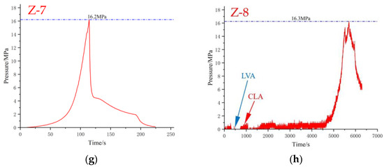
Figure 18.
Treatment pressure curve of each specimen (a–h).
5. Conclusions
This paper presents the results of acid fracturing tests under true triaxial conditions conducted on large size specimens prepared from natural outcrops of carbonate rocks. Different loading pressures and various acid systems have been applied to investigate the influence of various factors on fracture propagation. After testing, specimens were cut into thin slices, and scanned by using high-resolution camera equipment, and reconstructed in the Avizo software to create a three-dimensional digital model of the fractures, which was then analyzed using statistical techniques. The findings reveal the following:
- (1)
- A clear 3D fracture structure of a carbonate rock specimen after acid fracturing can be effectively established by using the novel method of fracture network construction proposed in this study without compromising the extraction of the fracture parameters. This method is more precise than the method of knocking specimens into pieces and scanning, and it has advantages over the method of CT X-ray scanning when dealing with large specimens.
- (2)
- The post-experimental structure demonstrates that the presence of natural fractures facilitates the formation of the fracture network. When a compression fracture contacts a natural fracture, it will penetrate if the angle between the two is large; conversely, the two will merge if the angle is small.
- (3)
- The length of the fracture increases with the increase in the horizontal stress difference, and the direction tends to develop parallel to σH. This results in a larger fracture width in the primary fracture and less development of the secondary fracture.
- (4)
- The experimental results obtained using different acid systems were compared, and it was found that the fracture width and fracture roughness formed by the pumping scheme with SW as a precursor and subsequent alternating injections of high-viscosity acid and crosslinked acid were superior to those of the combination of low-viscosity and crosslinked acid, and superior to those of single-acid injection and water injection. These findings can provide guidance for the optimization of the on-site process.
By reconstructing the fracture network using Avizo, we can determine the impact of various factors on fracture propagation, thereby providing a highly efficient acid system for construction sites. However, due to the small sample size used in our experiments, we were unable to fully simulate fracture propagation at the formation scale. It is suggested to use samples with a side length of more than 500 mm for fracturing simulation experiments, and use numerical simulation technology to simulate the trend of the fracture propagation in engineering scale. Combined with the experimental and numerical simulation results, the quantitative characteristics of a fracture propagation law can be further obtained.
Author Contributions
Conceptualization, C.J.; methodology, C.J.; software, C.J. and K.W.; formal analysis, C.J. and J.Z.; investigation, J.Z. and M.D.; resources, Z.G.; data curation, H.M. and Y.L.; writing—original draft preparation, C.J., H.M. and Y.L.; writing—review and editing, C.J.; visualization, C.J. and M.D.; supervision, Z.G. All authors have read and agreed to the published version of the manuscript.
Funding
This work was supported by the project “Research on rock mechanics and law of fracture propagation of high-temperature rock body (contract no.: GCY/JL B12-77-XZ)”, the SINOPEC Research Institute of Petroleum Engineering Co., Ltd.
Data Availability Statement
The original contributions presented in the study are included in the article, further inquiries can be directed to the corresponding authors.
Conflicts of Interest
Author Jun Zhou was employed by the company Petroleum Engineering Co., Ltd., the remaining authors are in partnership with the company, so there is no conflict of interest between the authors. And the company also participated in the study scheme design and data analysis.
Nomenclature
| SW | Slippery water |
| HVA | High viscosity acid |
| LVA | Low viscosity acid |
| CLA | Crosslinked acid |
References
- Li, Y.; Kang, Z.; Xue, Z.; Zheng, S. Theories and practices of carbonate reservoirs development in China. Pet. Explor. Dev. 2018, 45, 712–722. [Google Scholar] [CrossRef]
- Zhang, X.M. The characteristics of Lower Ordovician fissure-vug carbonate oil and gas pools in Tahe oil field, Xinjiang. Pet. Explor. Dev. 2001, 28, 17–22. [Google Scholar] [CrossRef]
- Wang, Y.L.; Li, Y.P.; Cheng, X.S.; Zhou, F.; Che, M.; Zhang, F.; Peng, J.; Yang, X. A new acid fracturing technique for carbonate reservoirs with high-temperature and deep layer. Acta Pet. Sin. 2012, 33, 166. [Google Scholar] [CrossRef]
- Martirosyan, A.; Ilyushin, Y.; Afanaseva, O.; Kukharova, T.; Asadulagi, M.; Khloponina, V. Development of an Oil Field’s Conceptual Model. Int. J. Eng. 2025, 38, 381–388. [Google Scholar] [CrossRef]
- Weng, D.L.; Lei, Q.; Xu, Y.; Li, Y.; Li, D.; Xu, W. Network fracturing techniques and its application in the field. Acta Pet. Sin. 2011, 32, 280. [Google Scholar] [CrossRef]
- Xi, Y.F.; Li, L.C.; Li, M.; Huang, B.; Zhang, L.Y.; Li, A.S. Three-dimensional numerical simulation study of hydraulic fracture extension law in natural fractured strata. Sci. Technol. Innov. Her. 2017, 14, 41–42+45. [Google Scholar] [CrossRef]
- Wu, Z.Y.; Hu, Y.F.; Jiang, T.X.; Zhang, B.P.; Yao, Y.M.; Dong, N. Study on Propagation and Diversion Characteristics of Hydraulic Fractures in Vuggy Carbonate Reservoirs. Pet. Drill. Tech. 2022, 50, 90–96. [Google Scholar] [CrossRef]
- Muecke, T.W. Principles of acid stimulation. In Proceedings of the International Petroleum Exhibition and Technical Symposium, Beijing, China, 17 March 1982; p. SPE–10038-MS. [Google Scholar] [CrossRef]
- Aljawad, M.S.; Aljulaih, H.; Mahmoud, M.; Desouky, M. Integration of field, laboratory, and modeling aspects of acid fracturing: A comprehensive review. J. Pet. Sci. Eng. 2019, 181, 106158. [Google Scholar] [CrossRef]
- Xu, G. A review of acid pressurization technology in carbonate reservoirs. Oilfield Chem. 1997, 14, 175–179. [Google Scholar] [CrossRef]
- Manrique, J.F.; Husen, A.; Gupta, S.C.; Raju, A.V. Integrated stimulation applications and best practices for optimizing reservoir development through horizontal wells. In Proceedings of the SPE Asia Pacific Oil and Gas Conference and Exhibition, Brisbane, Australia, 16 October 2000; p. SPE–64384-MS. [Google Scholar] [CrossRef]
- Nasr-El-Din, H.A.; Al-Zahrani, A.; Still, J.W.; Lesko, T.M.; Kelkar, S.K. Laboratory evaluation of an innovative system for fracture stimulation of high-temperature carbonate reservoirs. In Proceedings of the International Conference on Oilfield Chemistry, Houston, TX, USA, 28 February 2007; p. SPE–106054-MS. [Google Scholar] [CrossRef]
- Lund, K.; Fogler, H.S.; McCune, C.C. Acidization—I. The dissolution of dolomite in hydrochloric acid. Chem. Eng. Sci. 1973, 28, 691-IN1. [Google Scholar] [CrossRef]
- Lund, K.; Fogler, H.S.; McCune, C.C.; Ault, J. Acidization—II. The dissolution of calcite in hydrochloric acid. Chem. Eng. Sci. 1975, 30, 825–835. [Google Scholar] [CrossRef]
- Nierode, D.E.; Kruk, K.F. An evaluation of acid fluid loss additives retarded acids, and acidized fracture conductivity. In Proceedings of the Fall Meeting of the Society of Petroleum Engineers of AIME, Las Vegas, NV, USA, 30 September 1973; p. SPE–4549-MS. [Google Scholar] [CrossRef]
- Coulter, A.W.; Crowe, C.W.; Barrett, N.D.; Miller, B. Alternate stages of pad fluid and acid provide improved leakoff control for fracture acidizing. In Proceedings of the SPE Annual Fall Technical Conference and Exhibition, New Orleans, LA, USA, 3–6 October 1976; p. SPE–6124-MS. [Google Scholar] [CrossRef]
- Mukherjee, H.; Cudney, G. Extension of acid fracture penetration by drastic fluid-loss control. J. Pet. Technol. 1993, 45, 102–105. [Google Scholar] [CrossRef]
- He, R.; Yang, Z.Z.; Li, X.G.; Chen, F.; Teng, D.L. The experimental evaluation of a new crosslinked acid fracturing fluid system. In Resources, Environment and Engineering; CRC Press: Boca Raton, FL, USA, 2014; pp. 259–264. [Google Scholar]
- Li, A.; Ju, Y.; Sun, X.; Zhong, Y.; Huang, B. Synthesizing and capability estimation of high-temperature and high-viscosity gelled acid system. Acta Pet. Sin. 2007, 28, 90. [Google Scholar] [CrossRef]
- Wang, Z.B.; Fu, M.J.; Song, Q.; Wang, M.; Zhao, X.; Wang, Y. Preparation and characteristic of cross-linked acid for high-temperature acid fracturing system of deep carbonate reservoirs. Oilfield Chem. 2017, 33, 601–606. [Google Scholar] [CrossRef]
- Wang, Y.; Yang, J.; Wang, T.; Hu, Q.; Lv, Z.; He, T. Visualization experiment of multi-stage alternating injection acid fracturing. Energy Rep. 2022, 8, 9094–9103. [Google Scholar] [CrossRef]
- Zhao, H.F.; Xiong, Y.G.; Zhen, H.B.; Liu, C.; Li, X. Experimental investigation on the fracture propagation of three-stage acid fracturing of tight sandstone gas reservoir. J. Pet. Sci. Eng. 2022, 211, 110143. [Google Scholar] [CrossRef]
- Li, Z.H.; Deng, P.; Yang, C.H.; Guo, Y.; Hou, L. Experimental study on mechanical properties and fracability evaluation of carbonate reservoirs. J. Guangxi Univ. 2019, 44, 1450–1460. [Google Scholar] [CrossRef]
- Deng, P.; Yang, C.H.; Guo, Y.T. Experimental study on damage mechanical characteristics of carbonate rock with acid treatments in northeast Sichuan. Chin. J. Under Ground Space Eng. 2019, 15, 708–718. [Google Scholar]
- Zhang, K.; Chen, M.; Zhou, C.; Dai, Y.; Liu, F.; Li, J. Study of alternating acid fracturing treatment in carbonate formation based on true tri-axial experiment. J. Pet. Sci. Eng. 2020, 192, 107268. [Google Scholar] [CrossRef]
- Mou, J.Y.; Zhang, S.C.; Zhang, Y. Acid leakoff mechanism in acid fracturing of naturally fractured carbonate oil reservoirs. Transp. Porous Media 2012, 91, 573–584. [Google Scholar] [CrossRef]
- Gomaa, A.M.; Mahmoud, M.A.; Nasr-El-Din, H.A. Effect of Shear Rate on the Propagation of Polymer-Based In-Situ-Gelled Acids Inside Carbonate Cores. SPE Prod. Oper. 2011, 26, 41–54. [Google Scholar] [CrossRef]
- Settari, A.; Sullivan, R.B.; Hansen, C. A new two-dimensional model for acid-fracturing design. SPE Prod. Facil. 2001, 16, 200–209. [Google Scholar] [CrossRef]
- Romero, J.; Gu, H.; Gulrajani, S.N. 3D transport in acid-fracturing treatments: Theoretical development and consequences for hydrocarbon production. SPE Prod. Facil. 2001, 16, 122–130. [Google Scholar] [CrossRef]
- Chang, X.; Qiu, G.Z.; Li, J.; Guo, Y.; Hu, Z.; Yang, H.; Zhang, X.; Liu, Y. Study on the influence of vertical stress difference coefficient on fracture characteristics of shale under high stress. Energy Sci. Eng. 2024, 12, 3227–3242. [Google Scholar] [CrossRef]
- Hou, B.; Zhang, R.; Chen, M.; Kao, J.; Liu, X. Investigation on acid fracturing treatment in limestone formation based on true tri-axial experiment. Fuel 2019, 235, 473–484. [Google Scholar] [CrossRef]
- Hou, B.; Dai, Y.F.; Zhang, K. Numerical simulation of pores connection by acid fracturing based on phase field method. Acta Pet. Sin. 2022, 43, 849. [Google Scholar] [CrossRef]
- Liu, T.Y.; Sheng, Y.S.; Li, Q.; Zhang, C.; Cui, M.; Yu, Z.; Cao, P. Hydraulic fracture propagation in fractured rock mass. Appl. Sci. 2022, 12, 5846. [Google Scholar] [CrossRef]
- Zeng, Q.; Li, T.; Bo, L.; Li, X.; Yao, J. Comprehensive Investigation of Factors Affecting Acid Fracture Propagation with Natural Fracture. Energies 2024, 17, 5386. [Google Scholar] [CrossRef]
- Liu, W.; Pan, Z.H.; Zhang, X.; Wei, Y.; Zhao, L.; Zhu, X.; Zhao, Y.; Guo, Q. Experimental Study of the Fracture Network Expansion Mechanism and Three-Dimensional Reconstruction Characteristic of High-Rank Coal in Guizhou Province, China. ACS Omega 2023, 8, 6361–6375. [Google Scholar] [CrossRef]
- Barrett, L.K.; Yust, C.S. Some fundamental ideas in topology and their application to problems in metallography. Metallography 1970, 3, 1–33. [Google Scholar] [CrossRef]
- Li, W.; Sun, W.F.; Tang, P.; Yan, T.; Li, Y.; Ji, Z. Method for rock fracture network characterization based on topological structure. Nat. Gas Ind. 2017, 37, 22–27. [Google Scholar] [CrossRef]


Disclaimer/Publisher’s Note: The statements, opinions and data contained in all publications are solely those of the individual author(s) and contributor(s) and not of MDPI and/or the editor(s). MDPI and/or the editor(s) disclaim responsibility for any injury to people or property resulting from any ideas, methods, instructions or products referred to in the content. |
© 2025 by the authors. Licensee MDPI, Basel, Switzerland. This article is an open access article distributed under the terms and conditions of the Creative Commons Attribution (CC BY) license (https://creativecommons.org/licenses/by/4.0/).