
A Fuzzy Inertia-Based Virtual Synchronous Generator Model for Managing Grid Frequency Under Large-Scale Electric Vehicle Integration


Abstract
1. Introduction
- Theoretical groundwork: This paper comprehensively presents the theoretical rationale of an inertia-adaptive VSG and its pivotal role in enhancing power grid frequency stability. These theoretical foundations provide a solid basis for future investigations in this domain;
- Fuzzy inertia-based VSG: A novel fuzzy inertia-based VSG methodology is introduced to improve the frequency stability of power grids grappling with the integration of large-scale EVs. This innovative approach is attuned to the fact that large-scale EV charging does not always occur concurrently. Consequently, the proposed fuzzy method takes into account both steady-state and dynamic scenarios, which can ensure that the power grid maintains frequency stability during large-scale EV charging events without compromising response time when the power grid works stably;
- Adaptive output scaling: By incorporating alternative output coefficients, the new fuzzy inertia controller can dynamically modulate the entire VSG control system in response to the magnitude of frequency and frequency deviations.
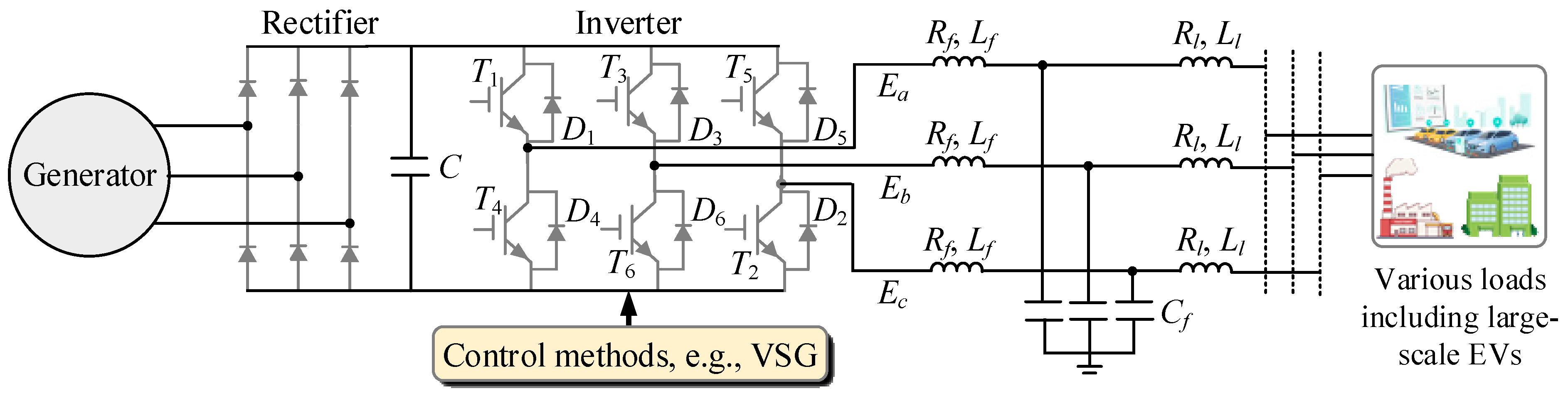
2. Basic VSG Strategy Used for Power Grids with Large-Scale EV Integration
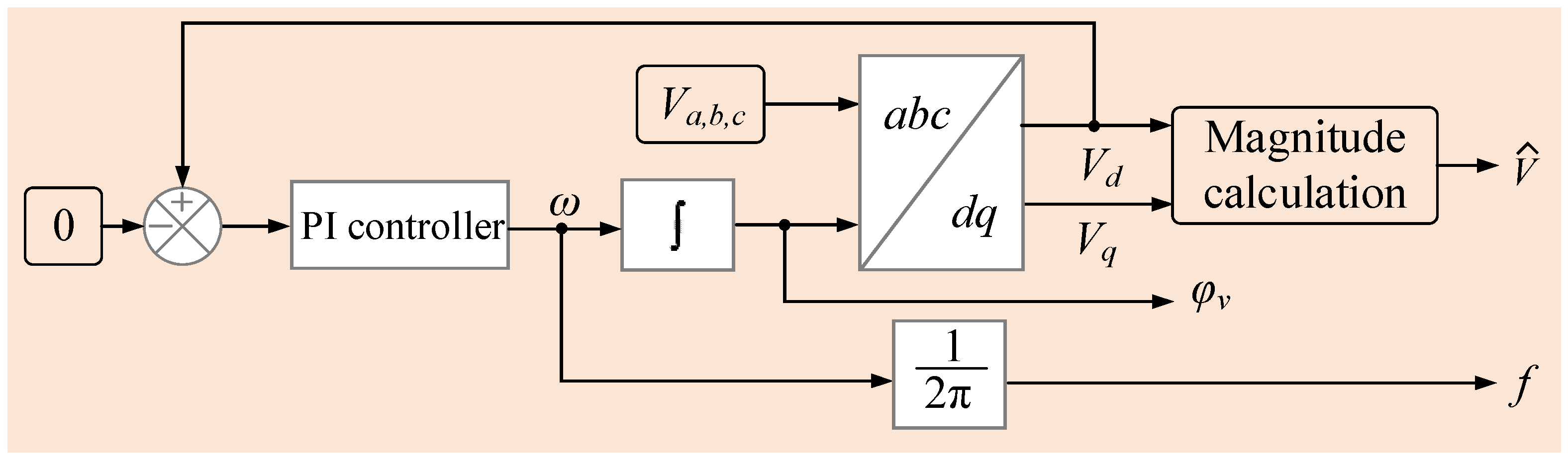
2.1. Phase-Locked Loop
2.2. Power Calculation
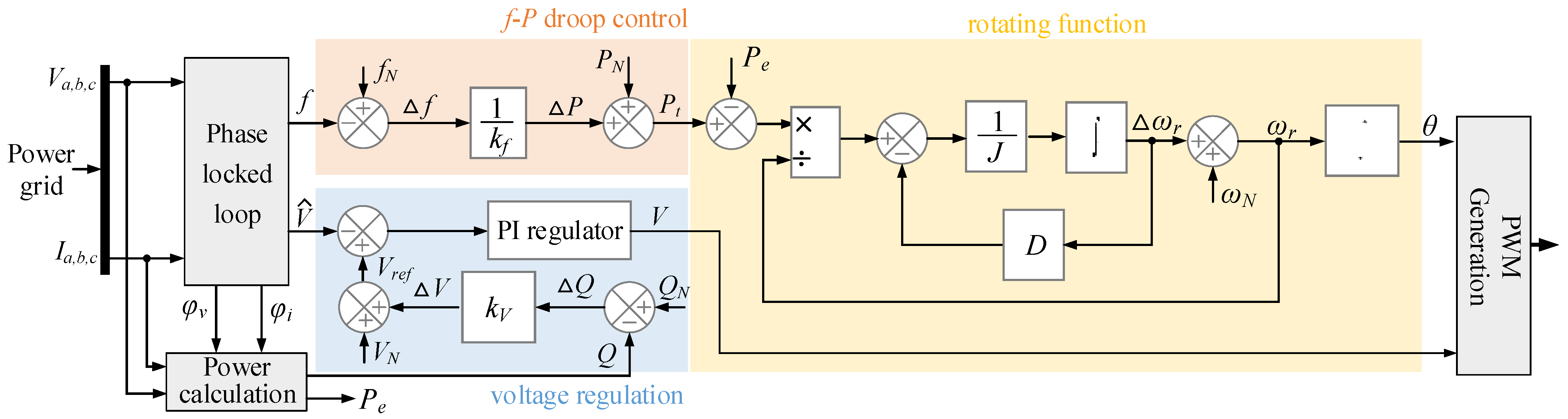
2.3. Voltage Regulation
2.4. f-P Droop Control
2.5. Rotating Function
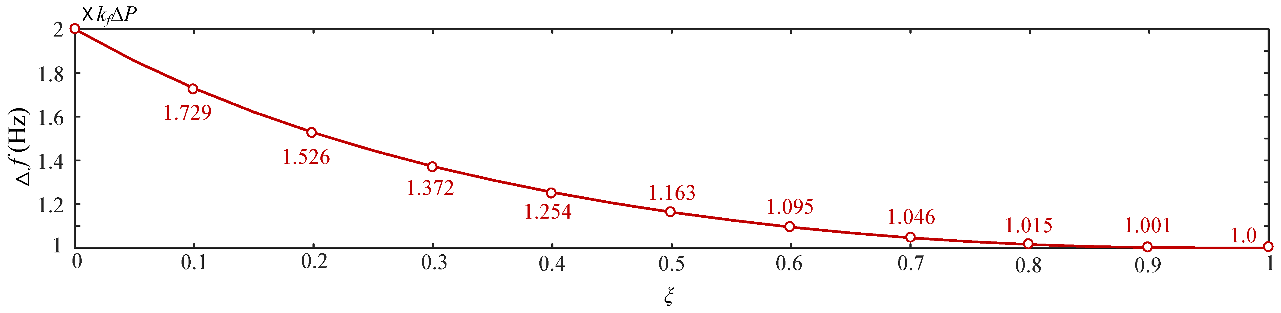
3. Relationship Between Inertia and Frequency Change
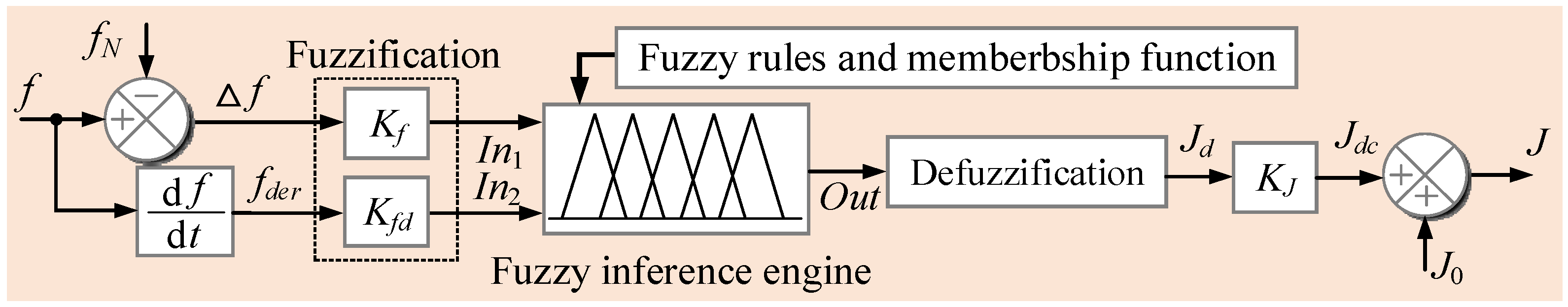
4. Proposed Fuzzy Adaptive Inertia-Based VSG Technique
4.1. Input
4.2. Fuzzification
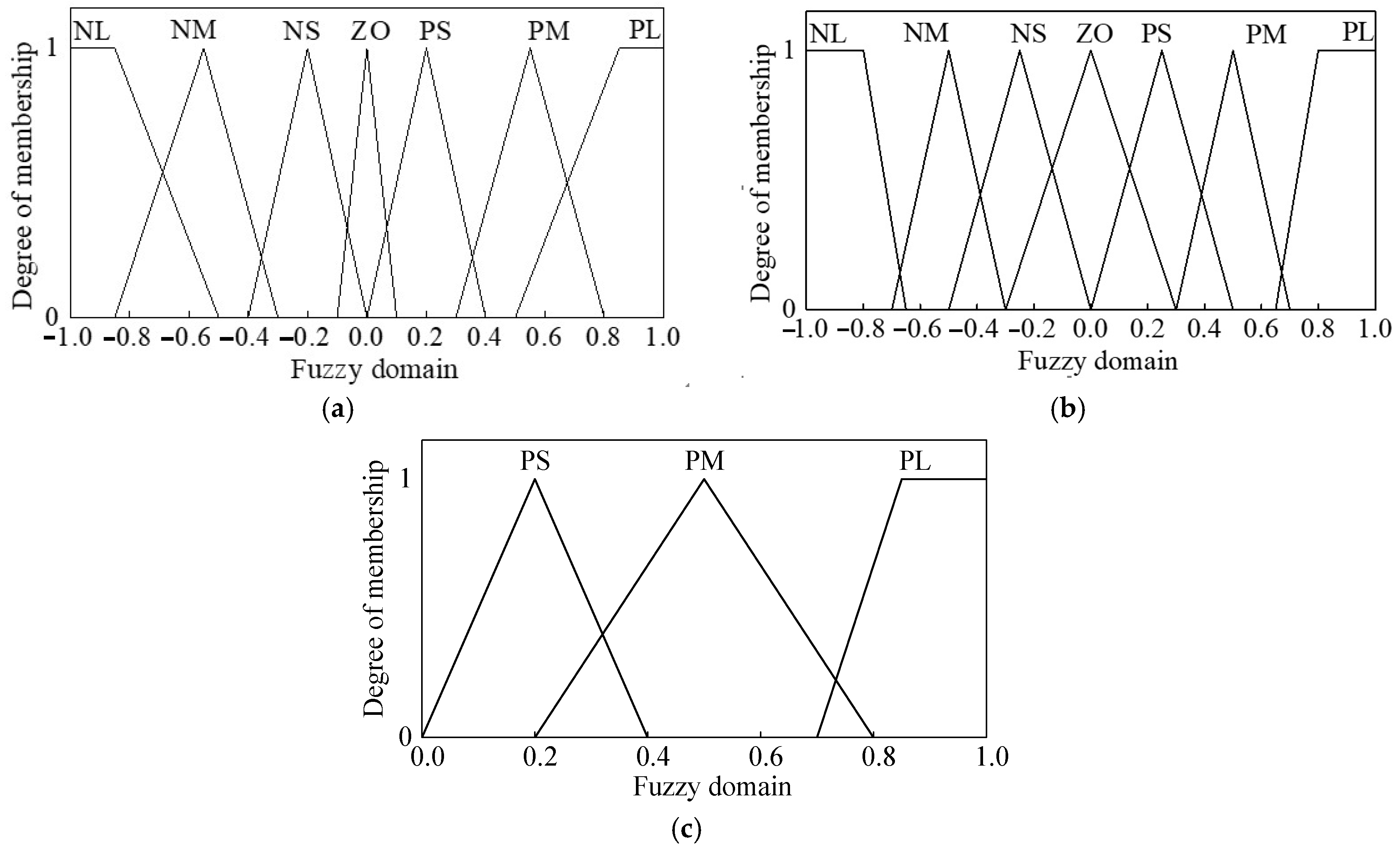
4.3. Fuzzy Rules and Mebership Function
- (a)
- Fuzzy rules
- (b)
- Membership function
4.4. Fuzzy Inference Engine
4.5. Defuzzification
4.6. Output
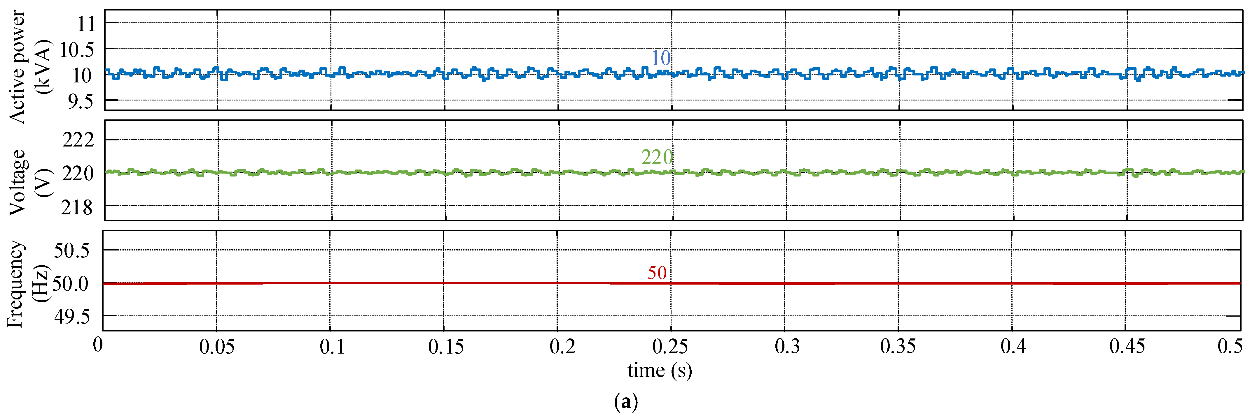
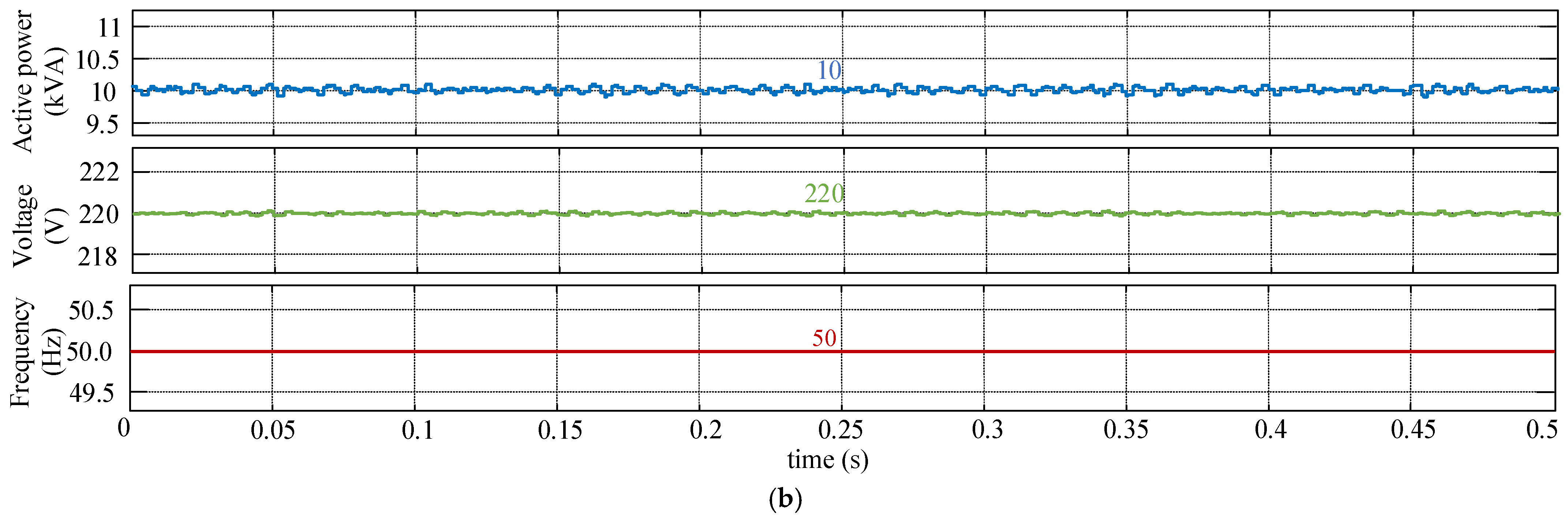
5. Verification Results
5.1. Simulation Results
- (a)
- Steady-state performance
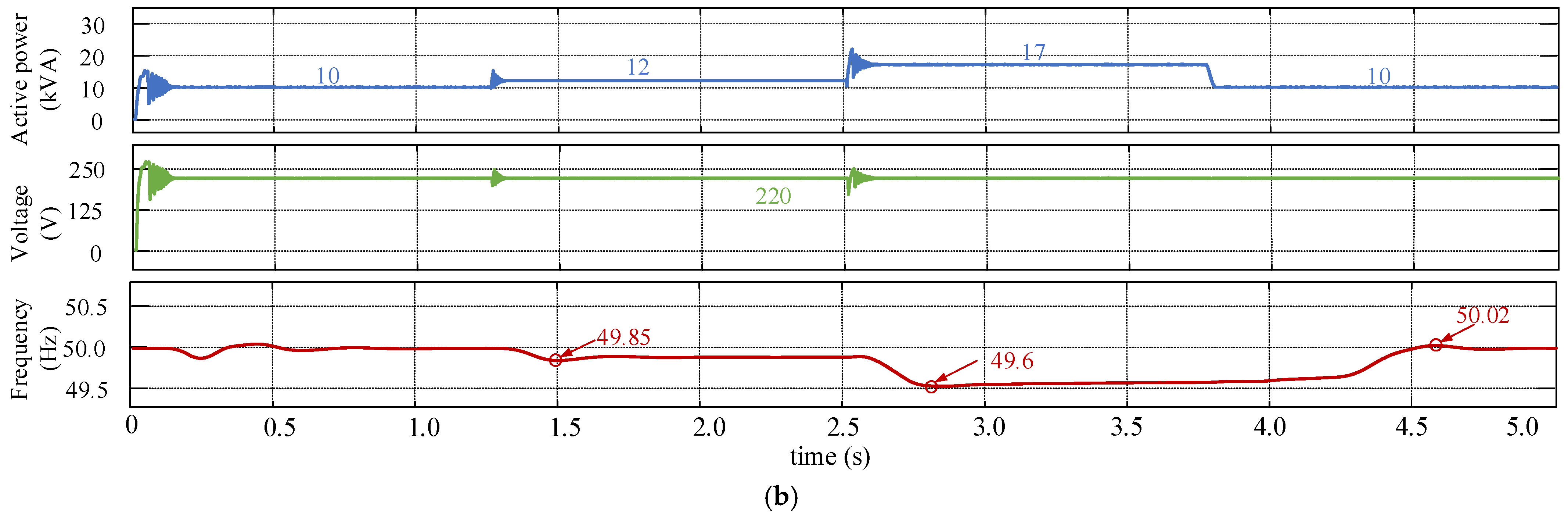
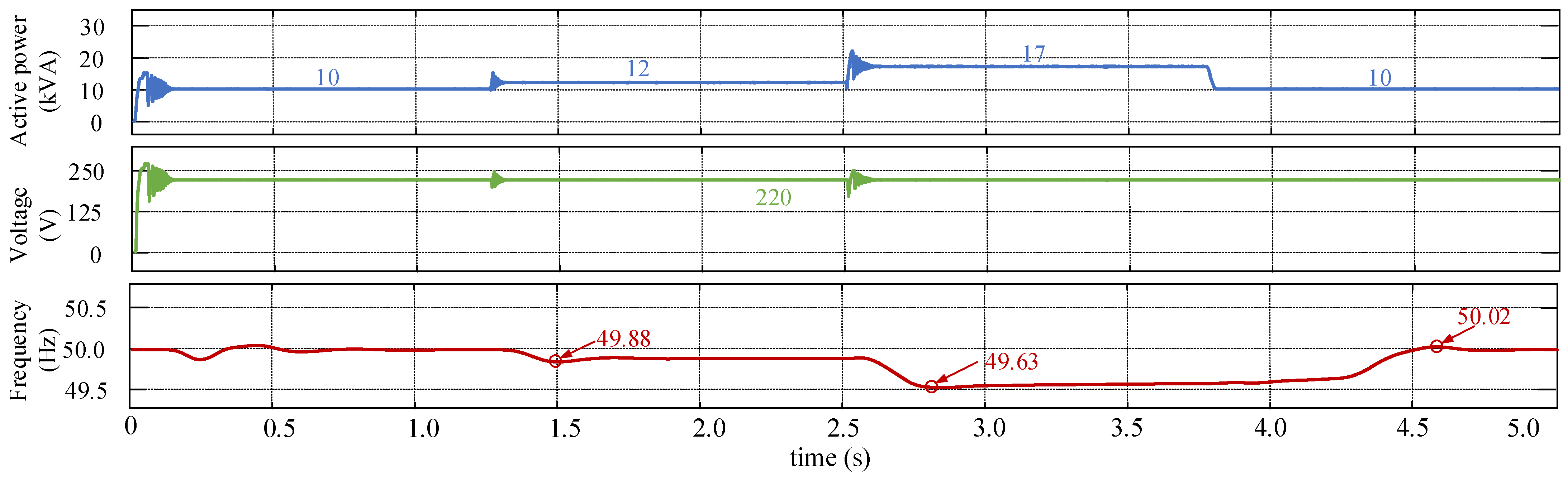
- (b)
- Dynamic performance
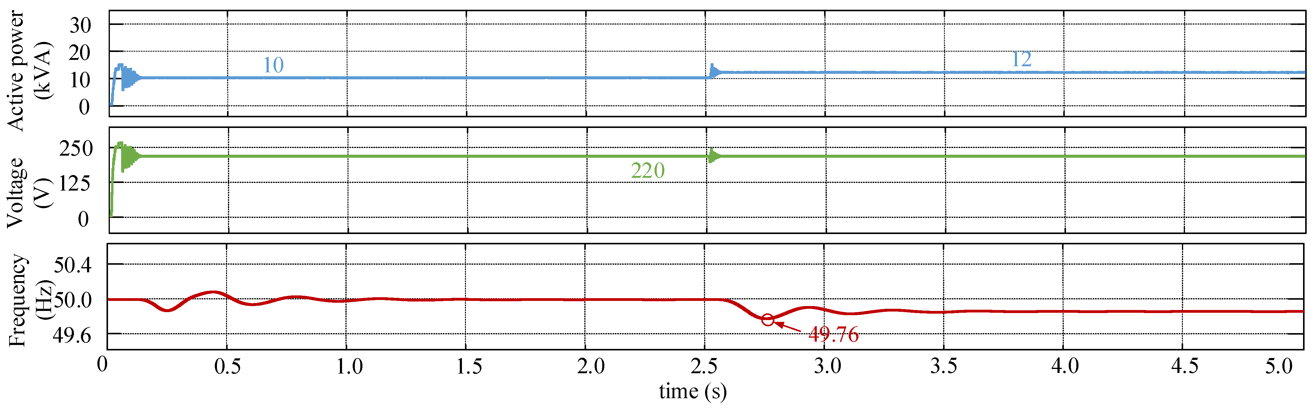
- (c)
- Traditional droop control
5.2. Discussion of Results
6. Conclusions
- Establishing a robust theoretical framework to elucidate the critical relationship between virtual inertia and grid frequency stability, providing valuable insights for future investigations;
- Developing an innovative fuzzy inertia-based VSG methodology, designed to dynamically adjust to varying grid conditions and EV charging demands, ensuring stability without sacrificing transient performance;
- Incorporating adaptive output scaling factors, enhancing the control system’s responsiveness to both steady-state and dynamic scenarios;
- The empirical results demonstrated the proposed method’s superior performance in mitigating frequency fluctuations, achieving improved stability and responsiveness compared to traditional VSGs and droop control strategies. Specifically, the proposed method reduces the maximum frequency change by 25% during load transitions, with a peak variation of 0.15 Hz compared to 0.2 Hz for the traditional VSG. These findings underscore the practical value of the fuzzy adaptive inertia control strategy in addressing real-world grid challenges posed by the rapid adoption of EVs.
Author Contributions
Funding
Data Availability Statement
Conflicts of Interest
References
- Hao, H.; Mu, Z.; Jiang, S.; Liu, Z.; Zhao, F. GHG Emissions from the Production of Lithium-Ion Batteries for Electric Vehicles in China. Sustainability 2017, 9, 504. [Google Scholar] [CrossRef]
- Gan, C.; Li, X.; Yu, Z.; Ni, K.; Wang, S.; Qu, R. Modular Seven-Leg Switched Reluctance Motor Drive With Flexible Winding Configuration and Fault-Tolerant Capability. IEEE Trans. Transp. Electrif. 2023, 9, 2711–2722. [Google Scholar] [CrossRef]
- Wirasingha, S.G.; Emadi, A. Classification and Review of Control Strategies for Plug-In Hybrid Electric Vehicles. IEEE Trans. Veh. Technol. 2011, 60, 111–122. [Google Scholar] [CrossRef]
- Xu, C.; Behrens, P.; Gasper, P.; Smith, K.; Hu, M.; Tukker, A.; Steubing, B. Electric Vehicle Batteries Alone Could Satisfy Short-Term Grid Storage Demand by As Early As 2030. Nat. Commun. 2023, 14, 119. [Google Scholar] [CrossRef]
- Hossain, S.; Rokonuzzaman, M.; Rahman, K.S.; Habib, A.K.M.A.; Tan, W.-S.; Mahmud, M.; Chowdhury, S.; Channumsin, S. Grid-Vehicle-Grid (G2V2G) Efficient Power Transmission: An Overview of Concept, Operations, Benefits, Concerns, and Future Challenges. Sustainability 2023, 15, 5782. [Google Scholar] [CrossRef]
- Rodrigues, E.M.G.; Osório, G.J.; Godina, R.; Bizuayehu, A.W.; Lujano-Rojas, J.M.; Catalão, J.P.S. Grid Code Reinforcements for Deeper Renewable Generation in Insular Energy Systems. Renew. Sustain. Energy Rev. 2016, 53, 163–177. [Google Scholar] [CrossRef]
- Kene, R.O.; Olwal, T.O. Energy Management and Optimization of Large-Scale Electric Vehicle Charging on the Grid. World Electr. Veh. J. 2023, 14, 95. [Google Scholar] [CrossRef]
- Zhang, W.; Wen, Y.; Chung, C.Y. Impedance-Based Online Estimation of Nodal Inertia and Primary Frequency Regulation Capability. IEEE Trans. Power Syst. 2023, 38, 2748–2760. [Google Scholar] [CrossRef]
- Magdy, G.; Bakeer, A.; Nour, M.; Petlenkov, E. A New Virtual Synchronous Generator Design Based on the SMES System for Frequency Stability of Low-Inertia Power Grids. Energies 2020, 13, 5641. [Google Scholar] [CrossRef]
- Li, C.; Yang, Y.; Mijatovic, N.; Dragicevic, T. Frequency Stability Assessment of Grid-Forming VSG in Framework of MPME With Feedforward Decoupling Control Strategy. IEEE Trans. Ind. Electron. 2022, 69, 6903–6913. [Google Scholar] [CrossRef]
- Gong, C.; Li, Y.R.; Zargari, N.R. An Overview of Advancements in Multimotor Drives: Structural Diversity, Advanced Control, Specific Technical Challenges, and Solution. Proc. IEEE 2024, 112, 184–209. [Google Scholar] [CrossRef]
- Yap, K.Y.; Sarimuthu, C.R.; Lim, J.M.-Y. Virtual Inertia-Based Inverters for Mitigating Frequency Instability in Grid-Connected Renewable Energy System: A Review. Appl. Sci. 2019, 9, 5300. [Google Scholar] [CrossRef]
- Wang, J.; Saraswat, G. Study of Inverter Control Strategies on the Stability of Low-Inertia Microgrid Systems. In Proceedings of the IECON 2022—48th Annual Conference of the IEEE Industrial Electronics Society, Brussels, Belgium, 17–20 October 2022; pp. 1–6. [Google Scholar]
- Stanojev, O.; Markovic, U.; Aristidou, P.; Hug, G. Improving Stability of Low-Inertia Systems Using Virtual Induction Machine Synchronization for Grid-Following Converters. IEEE Trans. Power Syst. 2023, 38, 2290–2303. [Google Scholar] [CrossRef]
- Curi, S.; Groß, D.; Dörfler, F. Control of Low-Inertia Power Grids: A Model Reduction Approach. In Proceedings of the 2017 IEEE 56th Annual Conference on Decision and Control (CDC), Melbourne, VIC, Australia, 12–15 December 2017; pp. 5708–5713. [Google Scholar]
- Beck, H.P.; Hesse, R. Virtual synchronous machine. In Proceedings of the International Conference on Electrical Power Quality & Utilisation, Barcelona, Spain, 9–11 October 2007; pp. 1–6. [Google Scholar]
- Zhong, Q.; Weiss, G. Synchronverters: Inverters That Mimic Synchronous Generators. IEEE Trans. Ind. Electron. 2011, 58, 1259–1267. [Google Scholar] [CrossRef]
- Haritha, M.S.; Nair, D.S. Review on Virtual Synchronous Generator (VSG) for Enhancing Performance of Microgrid. In Proceedings of the 2018 International Conference on Power, Signals, Control and Computation (EPSCICON), Thrissur, India, 6–10 January 2018; pp. 1–5. [Google Scholar]
- Li, D.; Zhu, Q.; Lin, S.; Bian, X.Y. A Self-Adaptive Inertia and Damping Combination Control of VSG to Support Frequency Stability. IEEE Trans. Energy Convers. 2017, 32, 397–398. [Google Scholar] [CrossRef]
- Wang, L.; Zhou, H.; Hu, X.; Hou, X.; Su, C.; Sun, K. Adaptive Inertia and Damping Coordination (AIDC) Control for Grid-Forming VSG to Improve Transient Stability. Electronics 2023, 12, 2060. [Google Scholar] [CrossRef]
- Liang, Y.; He, Y.; Niu, Y. Microgrid Frequency Fluctuation Attenuation Using Improved Fuzzy Adaptive Damping-Based VSG Considering Dynamics and Allowable Deviation. Energies 2020, 13, 4885. [Google Scholar] [CrossRef]
- Ding, J.; Zhang, J.; Ma, Z. VSG Inertia and Damping Coefficient Adaptive Control. In Proceedings of the 2020 Asia Energy and Electrical Engineering Symposium (AEEES), Chengdu, China, 29–31 May 2020; pp. 431–435. [Google Scholar]
- Li, X.; Chen, G. Improved Adaptive Inertia Control of VSG for Low Frequency Oscillation Suppression. In Proceedings of the 2018 IEEE International Power Electronics and Application Conference and Exposition (PEAC), Shenzhen, China, 4–7 November 2018; pp. 1–5. [Google Scholar]
- Fan, W.; Yan, X.; Hua, T. Adaptive Parameter Control Strategy of VSG for Improving System Transient Stability. In Proceedings of the 2017 IEEE 3rd International Future Energy Electronics Conference and ECCE Asia (IFEEC 2017—ECCE Asia), Kaohsiung, Taiwan, 3–7 June 2017; pp. 2053–2058. [Google Scholar]
- Wang, F.; Zhang, L.; Feng, X.; Guo, H. An Adaptive Control Strategy for Virtual Synchronous Generator. IEEE Trans. Ind. Appl. 2018, 54, 5124–5133. [Google Scholar] [CrossRef]
- Karimi, A.; Khayat, Y.; Naderi, M.; Dragicevic, T.; Mirzaei, R.; Blaabjerg, F.; Bevrani, H. Inertia Response Improvement in AC Microgrids: A Fuzzy-Based Virtual Synchronous Generator Control. IEEE Trans. Power Electron. 2020, 35, 4321–4331. [Google Scholar] [CrossRef]
- Zheng, J.; Wang, A.; Zhang, T.; Zhang, H.; Gu, N. Improved Adaptive Control Strategy of Inertia for Virtual Synchronous Generator Based on Fuzzy Control. In Proceedings of the 2019 Chinese Control Conference (CCC), Guangzhou, China, 27–30 July 2019; pp. 2531–2535. [Google Scholar]
- Xu, H.; Su, J.; Liu, N.; Shi, Y. A Grid-Supporting Photovoltaic System Implemented by a VSG with Energy Storage. Energies 2018, 11, 3152. [Google Scholar] [CrossRef]
- Koiwa, K.; Inoo, K.; Zanma, T.; Liu, K. Virtual Voltage Control of VSG for Overcurrent Suppression Under Symmetrical and Asymmetrical Voltage Dips. IEEE Trans. Ind. Electron. 2022, 69, 11177–11186. [Google Scholar] [CrossRef]
- Sakaeda, S.; Asano, M.; Sugimoto, S.; Verma, S.C.; Uda, R.; Kuroda, K. Studies on Stabilizing a Massive PV Penetrated Power System Using VSG. In Proceedings of the 2017 IEEE PES Innovative Smart Grid Technologies Conference Europe (ISGT-Europe), Turin, Italy, 26–29 September 2017; pp. 1–6. [Google Scholar]
- Gong, C.; Hu, Y.; Gao, J.; Wang, Y.; Yan, L. An Improved Delay-Suppressed Sliding-Mode Observer for Sensorless Vector-Controlled PMSM. IEEE Trans. Ind. Electron. 2019, 67, 5913–5923. [Google Scholar] [CrossRef]
- Imai, H.; Orihara, D.; Iioka, D.; Saitoh, H. A Novel Virtual Synchronous Generator Control of PMSG-Based Wind Generation System to Enhance Transient Stability of Power System. In Proceedings of the 2018 IEEE Electronic Power Grid (eGrid), Charleston, SC, USA, 12–14 November 2018; pp. 1–6. [Google Scholar]
- Zhang, W.; Yan, X.; Huang, H. Performance Tuning for Power Electronic Interfaces Under VSG Control. Appl. Sci. 2020, 10, 953. [Google Scholar] [CrossRef]
- Kondratenko, Y.P.; Kuntsevich, V.M.; Chikrii, A.A. Part II Advances in Control Systems Application. In Recent Developments in Automatic Control Systems; River Publishers: Rome, Italy, 2022; pp. 165–166. [Google Scholar]
- Lu, J. Automatic Control Theory, 2nd ed.; Machinery Industry Press: Xi’an, China, 2009; pp. 238–241. [Google Scholar]
- Hacene, N.; Mendil, B.; Bechouat, M.; Sadouni, R. Comparison Between Fuzzy and Non-fuzzy Ordinary If–Then Rule-Based Control for the Trajectory Tracking of a Differential Drive Robot. Int. J. Fuzzy Syst. 2022, 24, 3666–3687. [Google Scholar] [CrossRef]
- Wu, D. Twelve Considerations in Choosing Between Gaussian and Trapezoidal Membership Functions in Interval Type-2 Fuzzy Logic Controllers. In Proceedings of the 2012 IEEE International Conference on Fuzzy Systems, Brisbane, QLD, Australia, 10–15 June 2012; pp. 1–8. [Google Scholar]
- Tabakov, M.; Chlopowiec, A.B.; Chlopowiec, A.R. A Novel Classification Method Using the Takagi–Sugeno Model and a Type-2 Fuzzy Rule Induction Approach. Appl. Sci. 2023, 13, 5279. [Google Scholar] [CrossRef]
- Han, Y.; Chen, S.; Gong, C.; Zhao, X.; Zhang, F.; Li, Y. Accurate SM Disturbance Observer-Based Demagnetization Fault Diagnosis with Parameter Mismatch Impacts Eliminated for IPM Motors. IEEE Trans. Power Electron. 2023, 38, 5706–5710. [Google Scholar] [CrossRef]
- Wu, Z.; Wang, J.; Xing, Y.; Li, S.; Yi, J.; Zhao, C. Energy Management of Sowing Unit for Extended-Range Electric Tractor Based on Improved CD-CS Fuzzy Rules. Agriculture 2023, 13, 1303. [Google Scholar] [CrossRef]
- Chopra, K.; Shah, M.K.; Jain, S.; Mehrotra, A.; Agarwal, S.; Goyal, S. Analysis of Defuzzification Methods of a Fuzzy Logic Controller for Priority Control of Electric Vehicle Charging. In Proceedings of the 2023 5th International Conference on Energy, Power and Environment: Towards Flexible Green Energy Technologies (ICEPE), Shillong, India, 15–17 June 2023; pp. 1–6. [Google Scholar]


| In1 | ||||||||
|---|---|---|---|---|---|---|---|---|
| PL | PM | PS | ZO | NS | NM | NL | ||
| In2 | PL | PM | PL | PL | PL | PL | PL | PM |
| PM | PS | PM | PL | PM | PL | PM | PS | |
| PS | PS | PS | PM | PM | PM | PS | PS | |
| ZO | ZO | ZO | PM | PM | PM | ZO | ZO | |
| NS | PS | PS | PM | PM | PM | PS | PS | |
| NM | PS | PM | PL | PM | PL | PM | PS | |
| NL | PM | PL | PL | PL | PL | PL | PM | |
| Variable | Description | Value | Unit |
|---|---|---|---|
| PN | Rated active power | 10 | kVA |
| QN | Rated reactive power | 0 | kVA |
| VN | Rated output voltage | 220 | V |
| fN | Rated frequency | 50 | Hz |
| VDC | EV DC-bus voltage | 800 | V |
| Pch | Test charging power of EVs | 10, 12, 17 | kVA |
| Lf | Filter inductance | 0.18 | H |
| Cf | Filter capacitance | 10 | μF |
| J0 | Initial virtual inertia | 0.25 | kg·m2 |
| kf | Frequency droop coefficient | −2π × 10−4 | - |
| kV | Voltage droop coefficient | 0.0001 | - |
| D | Virtual damping | 4 | - |
| KJ | Scaling coefficient for output | 4 | - |
| Kf | Scaling coefficient for frequency | 1/50 | - |
| Kfd | Scaling coefficient for frequency change rate | 1/1000 | - |
| K | Inverter gain | 1 | - |
| kpv | Gain coefficient of voltage controller | 0.5 | - |
| kiv | Integral coefficient of voltage controller | 0.002 | - |
Disclaimer/Publisher’s Note: The statements, opinions and data contained in all publications are solely those of the individual author(s) and contributor(s) and not of MDPI and/or the editor(s). MDPI and/or the editor(s) disclaim responsibility for any injury to people or property resulting from any ideas, methods, instructions or products referred to in the content. |
© 2025 by the authors. Licensee MDPI, Basel, Switzerland. This article is an open access article distributed under the terms and conditions of the Creative Commons Attribution (CC BY) license (https://creativecommons.org/licenses/by/4.0/).
Share and Cite
Jia, Y.; Jin, Z. A Fuzzy Inertia-Based Virtual Synchronous Generator Model for Managing Grid Frequency Under Large-Scale Electric Vehicle Integration. Processes 2025, 13, 287. https://doi.org/10.3390/pr13010287
Jia Y, Jin Z. A Fuzzy Inertia-Based Virtual Synchronous Generator Model for Managing Grid Frequency Under Large-Scale Electric Vehicle Integration. Processes. 2025; 13(1):287. https://doi.org/10.3390/pr13010287
Chicago/Turabian StyleJia, Yajun, and Zhijian Jin. 2025. "A Fuzzy Inertia-Based Virtual Synchronous Generator Model for Managing Grid Frequency Under Large-Scale Electric Vehicle Integration" Processes 13, no. 1: 287. https://doi.org/10.3390/pr13010287
APA StyleJia, Y., & Jin, Z. (2025). A Fuzzy Inertia-Based Virtual Synchronous Generator Model for Managing Grid Frequency Under Large-Scale Electric Vehicle Integration. Processes, 13(1), 287. https://doi.org/10.3390/pr13010287