Abstract
The first principle of numerical modeling of die extrusion of energetic materials is carried out to reduce the needed pressure gradient along the die. The proposed new die design with a converging shape outlet appears to have a smaller pressure drop compared to the current U.S. Army Armament Research, Development and Engineering Center (ARDEC) die shape. The optimal shape was obtained by finite-volume fluid dynamics computations through a range of die designs. The presented computations have been performed for a 3D die equipped with different outflow pipes. The features of the flow field are obtained for the non-Newtonian fluid through the apparatus. The change of fluid model from Newtonian to non-Newtonian complying power law does not make a considerable change in velocity profile at outlets for the same mass flow rate. Nevertheless, there is a substantial increase in the pressure gradient needed to transport the fluid through the die. For the new proposed die design, apparent viscosity steadily drops along the centerline of the outlet. As the viscosity magnitude determines the needed pressure drop, the new die design with a converging shape outlet has a substantially smaller pressure drop compared to the current die.
1. Introduction
At the current state of the art, the design of manufacturing dies for energetic materials relies strongly on the experience of the die designer [1]. Numerical modes are used to a limited extent, although the future role of computer simulations is important for upgrading the manufacturing of energetic materials from batch mode to continuous mode and reducing safety risks [2,3,4]. In the future, costly and safety-concerning experiments of optimization of manufacturing of energetic materials should be replaced by multi-variant numerical simulations. The objective of the present study is to create a numerical model of the extrusion of energetic materials and demonstrate its usefulness for the optimization of die design to reduce the needed pressure gradient along the die and to explain the physical reasons for it.
Past studies were conducted to model the flow of energetic materials through multistrand dies. Ref. [5] showed that polymer-based energetic materials do not have elasticity and should be modeled as non-Newtonian fluids. Ref. [6] suggested that most of the energetic materials are either gels or multi-phase materials filled with suspensions of rigid particles. Generally, they exhibit high yield stress, which makes the flow behavior similar to that of plug flow. This kind of behavior can be modeled as viscoplastic material. Refs. [7,8] discussed how the viscoplastic fluids exhibit wall slip; nevertheless, Refs. [9,10] modeled the flow of energetic material with the no-slip conditions. In the current study, the flow of energetic material has been modeled as a viscoplastic one with a no-slip boundary condition at the walls of the die. For future studies, slip velocity will be added to the die’s walls, coupled with the viscoplastic model, to study the effect of slip on extrusion pressure and wall shear stress.
The motivation of the current study is that numerical simulations can uncover important internal details of the extrusion process, including velocity, pressure, shear stress, viscosity, and temperature distribution in dies, which is difficult and unsafe to obtain by experiments [11], with the ability of the proposed mathematical model to consider more physical features and new die designs to the description of physics of fluid flow of energetic materials in the future.
More broadly, the extrusion process is a common process in polymer processing, e.g., producing films, pipes, sheets, cables, and pellets. In each type of extrusion, the feed fluid is forced through a die to create the desired diameter and shape of the product. Die shape is important in these processes as it determines the diameter of the product, maintains the flow distribution uniform across the exit, and minimizes the needed pressure difference between the inlet and exit. A practical extrusion process often involves geometrically complex-shaped dies [12]. Converging-shaped [13] dies are common to achieve the maximum flow rate under laminar flow conditions. The approach can be used for a broad range of hydraulic systems to evaluate the needed pressure drop due to changes in the size and configuration of the cross-sectional area [14].
Baseline design parameters are listed below in Table 1.

Table 1.
Baseline design parameters for die design.
While in well-controlled laboratory experiments, many of the dies are long and cylindrical shaped to create a fully developed flow [9], practical industrial dies could be quite different as they are relatively short, tapered, and with multiple outlets (see Figure 1). To use this kind of die design, the pressure drop for these dies must be known before they are manufactured. Usually, the die design process is a trial and error-based method and requires a considerable amount of time and resources [15]. Numerical modeling is expected to complement the trial-and-error method for die design and reduce the number of experimental iterations and corresponding time and cost.

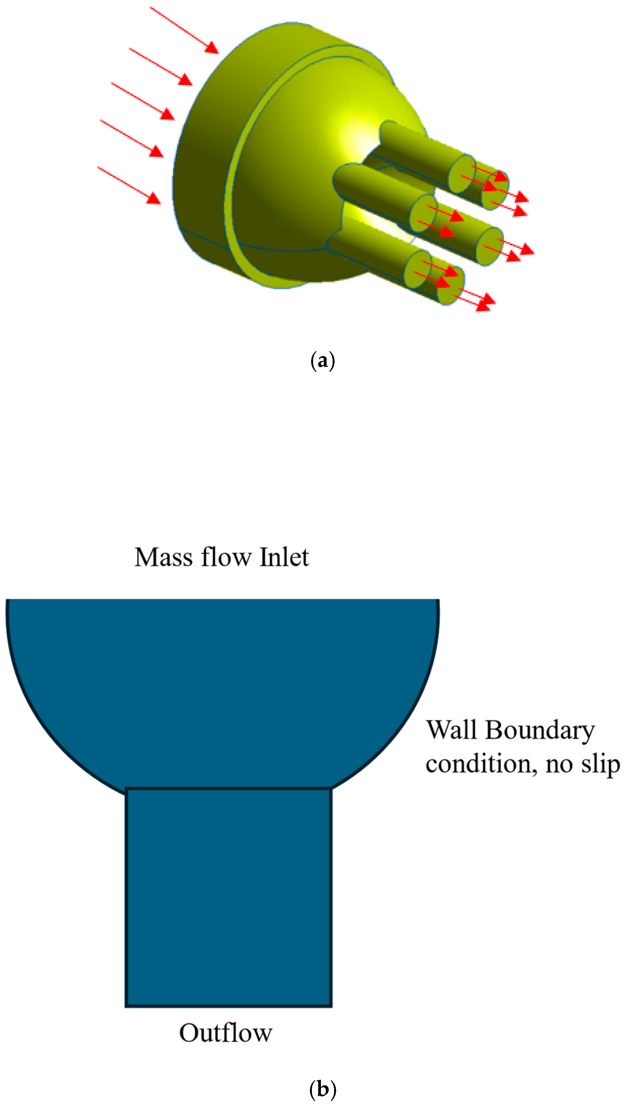
Figure 1.
Schematic of die (a) with shown flow direction and (b) boundary conditions.
In the current study, a multi-outlet tapered die has been used, which was developed by the US Army Research and Development Center (ARDEC) (see Table 1 and Figure 1). It is a relatively short die where the working non-Newtonian fluid is poured into a reservoir from which the fluid flow is distributed evenly among the six outlets, where each outlet has the same size and geometric profile. The goal of the current study is to develop a numerical model to simulate non-Newtonian flow through the die. Using the proposed model, the geometric design of the die is optimized to reduce apparent viscosity and, consequently, to reduce the pressure drop.
The study is composed as follows. In Section 2, the mathematical model, boundary conditions, numerical methodology, and validation of the approach are presented. In Section 3, non-Newtonian flow solutions for existing die are presented and discussed. In Section 4, a comparative numerical experiment was conducted on several die designs to investigate the effect of taper angle on pressure drop. In Section 5, the Conclusions are drawn.
2. Numerical Finite-Volume Model for the Die
Extrusion is a plastic deformation process in which liquid material flows through the die [16,17] (see Figure 1).
The 3D die flow is studied by numerical solution of the three-dimensional non-Newtonian Navier-Stokes equations using ANSYS/Fluent (Canonsburg, PA, USA) version 2020 R2 finite-volume software with a second-order central discretization scheme for viscous terms.
A single-phase fluid flow is assumed as no foam is expected to form inside the die [18]. The following assumptions are used in the current study:
- Incompressible, steady, laminar flow;
- No-slip velocity boundary conditions at rigid walls of the die [9,10];
- Uniform and constant die temperature;
- Constant volumetric flow rate;
- The effect of gravity is negligible.
The rise in temperature due to viscous effects has not been considered.
In recent Ref. [19], there is an isothermal assumption and no-slip assumption between the material and the die wall, leading to no-slip boundary conditions during the extrusion process. According to Ref. [19], the no-slip condition has been widely accepted in the literature (see references to prior studies therein).
The no-slip boundary condition corresponds to the upper limit of the needed pressure gradient compared to partial slip boundary conditions that will be explored in the future extension of the model.
As soon as the apparent viscosity decreases with temperature, the omission of temperature rise in the present mathematical model corresponds to the upper limit of viscosity and, therefore, to the upper limit (most stringent) case of the needed pressure gradient.
Under the above assumptions, the governing transport equations for mass and momentum in the vector form are used as follows:
Conservation of mass:
Conservation of momentum:
where u is velocity vector, P is static pressure, τ is the shear stress, ρ is the density of the fluid.
To set up ANSYS/Fluent boundary conditions, the inlet was set as a mass flow inlet, and the outlet was set up as an outflow condition. ANSYS/Fluent software uses the Semi-implicit Method for Pressure-linked Equations (SIMPLE) [20] to resolve velocity and pressure coupling. ANSYS/Fluent uses algebraic multigrid (AMG) to solve the Poisson equation for pressure correction. To reduce the computational time and ensure convergence of iterations, successive under-relaxation iterative method is used to solve the linear system, with relaxation coefficients equal to 0.5 for pressure correction and 0.7 for momentum equations. In this study, the convergence criteria of 10−4 for normalized residuals of discretized mass and momentum equations have been set up. The convergence requires up to ~15,000 iterations for the non-Newtonian flow model.
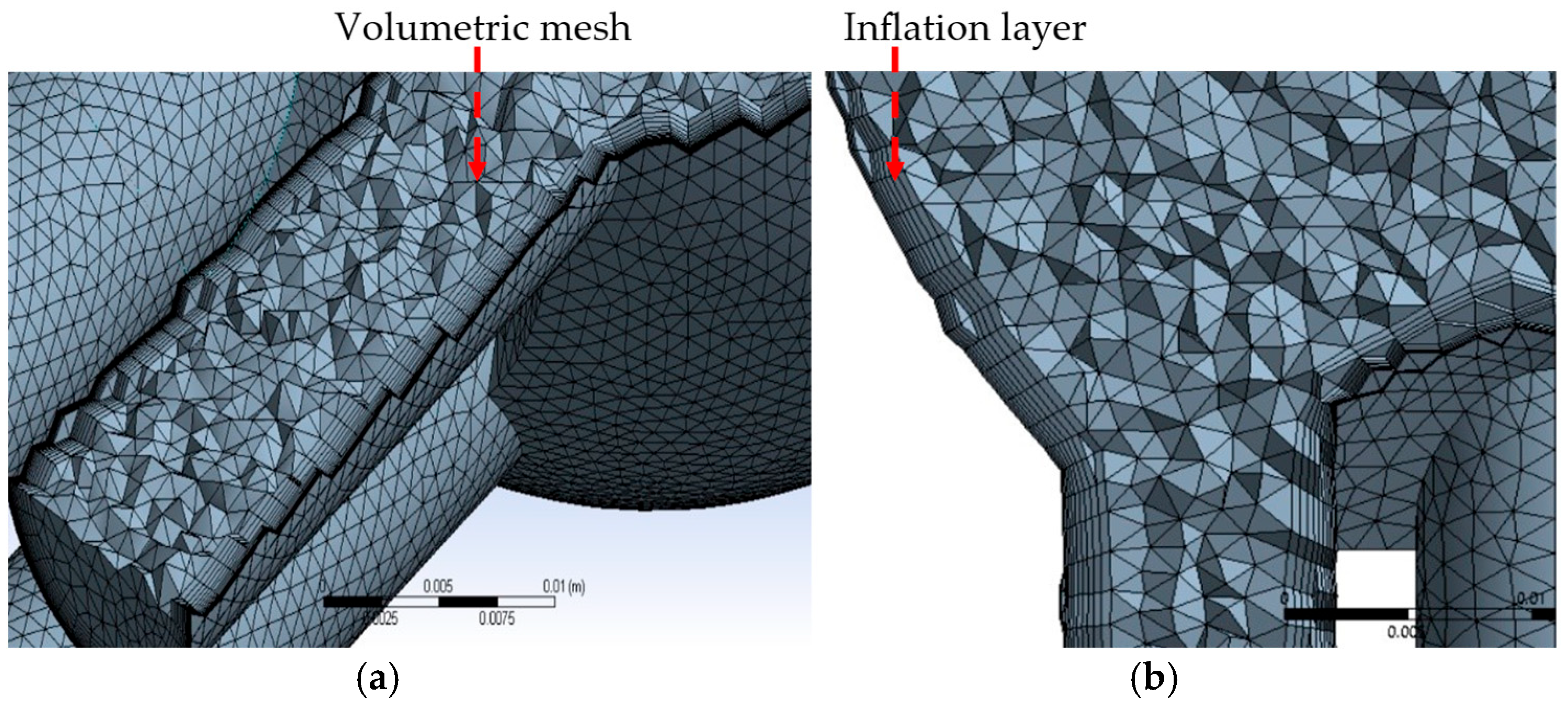
The schematic of finite-volume mesh is presented in Figure 2. The number of cells in the computational domain is equal to 165,264. Unstructured tetrahedral mesh has been used throughout the domain (see Figure 2a). So-called inflation grid layers have been created to form refined structured mesh near the walls of the die to resolve the boundary layer near the die wall (see Figure 2b).
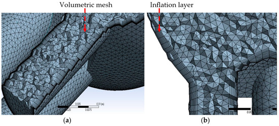
Figure 2.
Finite-volume mesh for the die: (a) surface mesh and volume mesh and (b) structured mesh inflation layers at the walls of the die.
3. Non-Newtonian Flow Models
Energetic material flow behaves as a non-Newtonian fluid where viscosity changes along with shear strain. In the current study, because of trade secrecy, the name of the fluid will not be disclosed; rather, the properties of the fluid have been specified and used. The generalized Newtonian approach has been considered to model the flow through the ARDEC die. A generalized fluid shear stress tensor, is written [21] as the following:
where is dynamic viscosity.
The major difference between Newtonian and non-Newtonian fluids resides in the viscosity definition of viscosity. For a Newtonian fluid, viscosity, which is the ratio of shear stress and strain, is constant, while for a non-Newtonian fluid, viscosity is not constant and varies with the shear strain . For a non-Newtonian fluid, the term apparent viscosity, is introduced. For a Newtonian fluid, this apparent viscosity is equal to dynamic viscosity [22]. In the current study, the working polymer fluid has been considered a power-law fluid, where the apparent viscosity of the fluid decreases as the shear rate increases [23] as in the following:
where is the flow consistency index, γ is the shear strain, and n is the Power-law index.
The properties of the polymer are provided by ARDEC and shown in Table 2. The density of the polymer appears in Table 1. The die walls are assumed to be smooth.
Table 2.
Polymer properties.
4. Results and Discussion
In this section, the non-Newtonian fluid flowing through the ARDEC die is computed, and results are discussed in terms of the velocity field, needed pressure gradient, and apparent viscosity (see Figure 3). The non-Newtonian power-law fluid follows Equation (4) and Table 2.
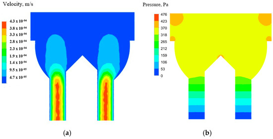
Figure 3.
Flowfield for the baseline die: (a) velocity and (b) pressure.
To study the velocity profile at different cross-sectional locations of the die, the velocity profiles are shown along the horizontal lines drawn in Figure 4. In Table 3, numbered lines with their corresponding vertical coordinates are given.
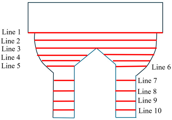
Figure 4.
Horizontal cross-sections in which velocity profiles are shown. The die exit corresponds to the origin.
Table 3.
Horizontal lines along which velocity profiles are shown with their vertical coordinates. The die exits correspond to zero of the vertical coordinates.
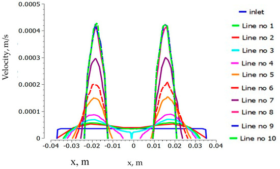
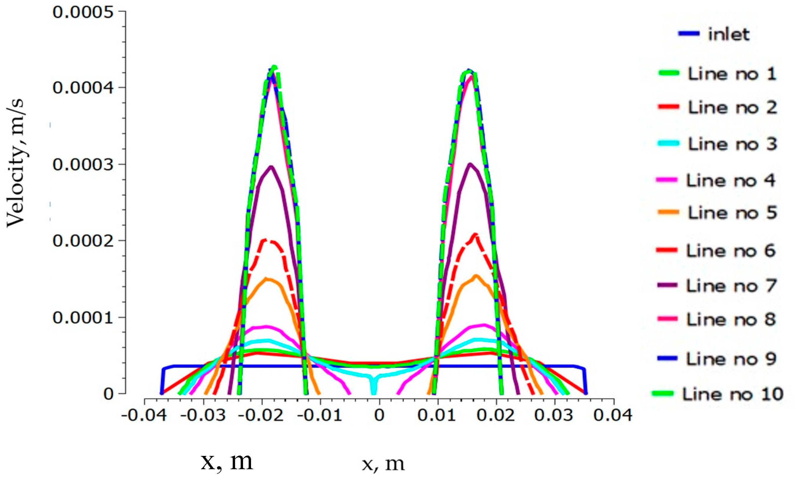
Figure 5.
Velocity profiles are at horizontal locations inside the die.
Velocity profiles at all horizontal locations show the shapes of velocity profiles and their magnitudes. For the non-Newtonian fluid, because of the non-linear relationship (Equation (4) between apparent viscosity and shear rate, the apparent viscosity does not remain constant through the domain (see Figure 6 and Figure 7).

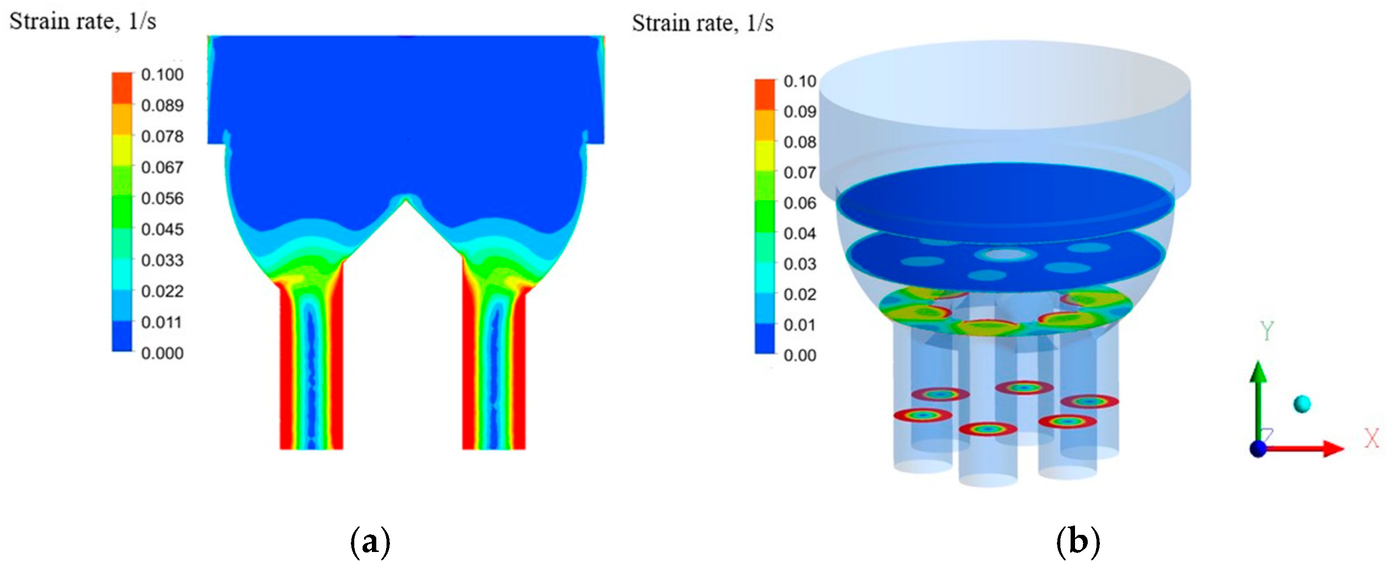
Figure 6.
Strain rate (a) at the X-Y plane and (b) at the set of horizontal planes at distances of 0.1 m, 0.3 m, 0.6 m, and 0.7 above the outlet.
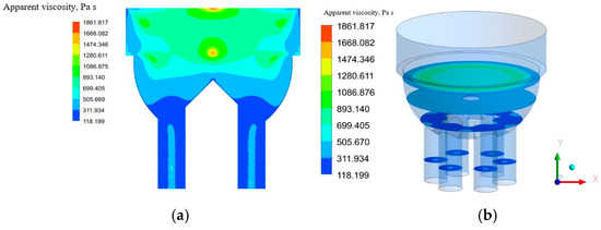
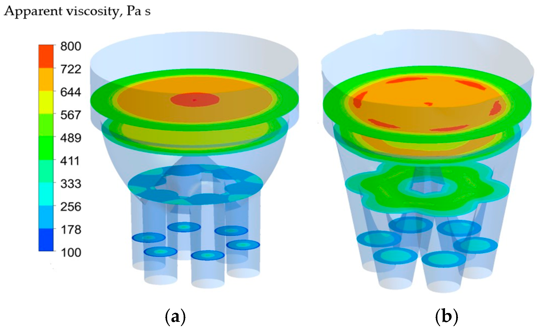
Figure 7.
Apparent viscosity for non-Newtonian fluid in die: (a) at the X-Y plane and (b) at horizontal planes at the same vertical locations as in the prior Figure.
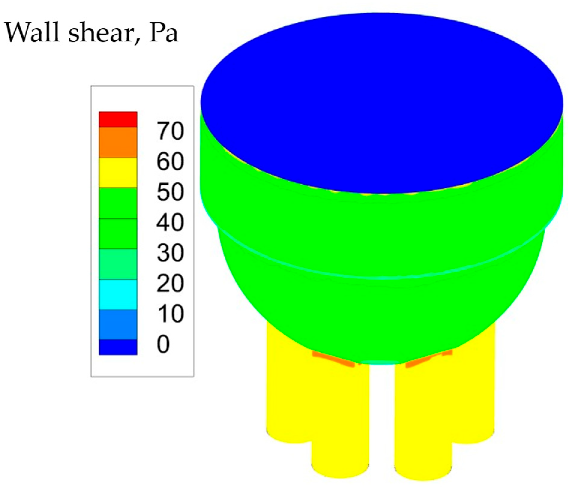
Figure 7 and Figure 8 show how the apparent viscosity varies along the die for the non-Newtonian working fluid. Figure 7a shows that along the center (X-Y) plane at the core of the die, viscosity is larger, while near the wall, due to the higher strain rate (see Figure 6a), the apparent viscosity is smaller. Wall shear stress increases along the flow direction (Figure 9). There is an abrupt increase of shear when the flow starts to enter the outlet pipes (narrow red areas in Figure 9). Because of high shear stress, flow starts to have larger deformation that causes higher shear strain. As the feed fluid is shear thinning, viscosity starts to reduce.
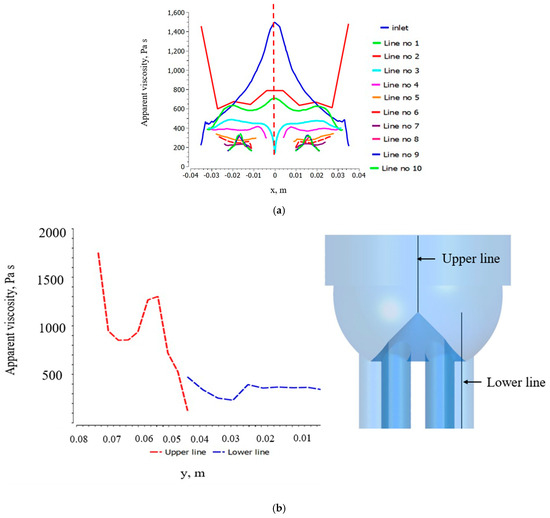
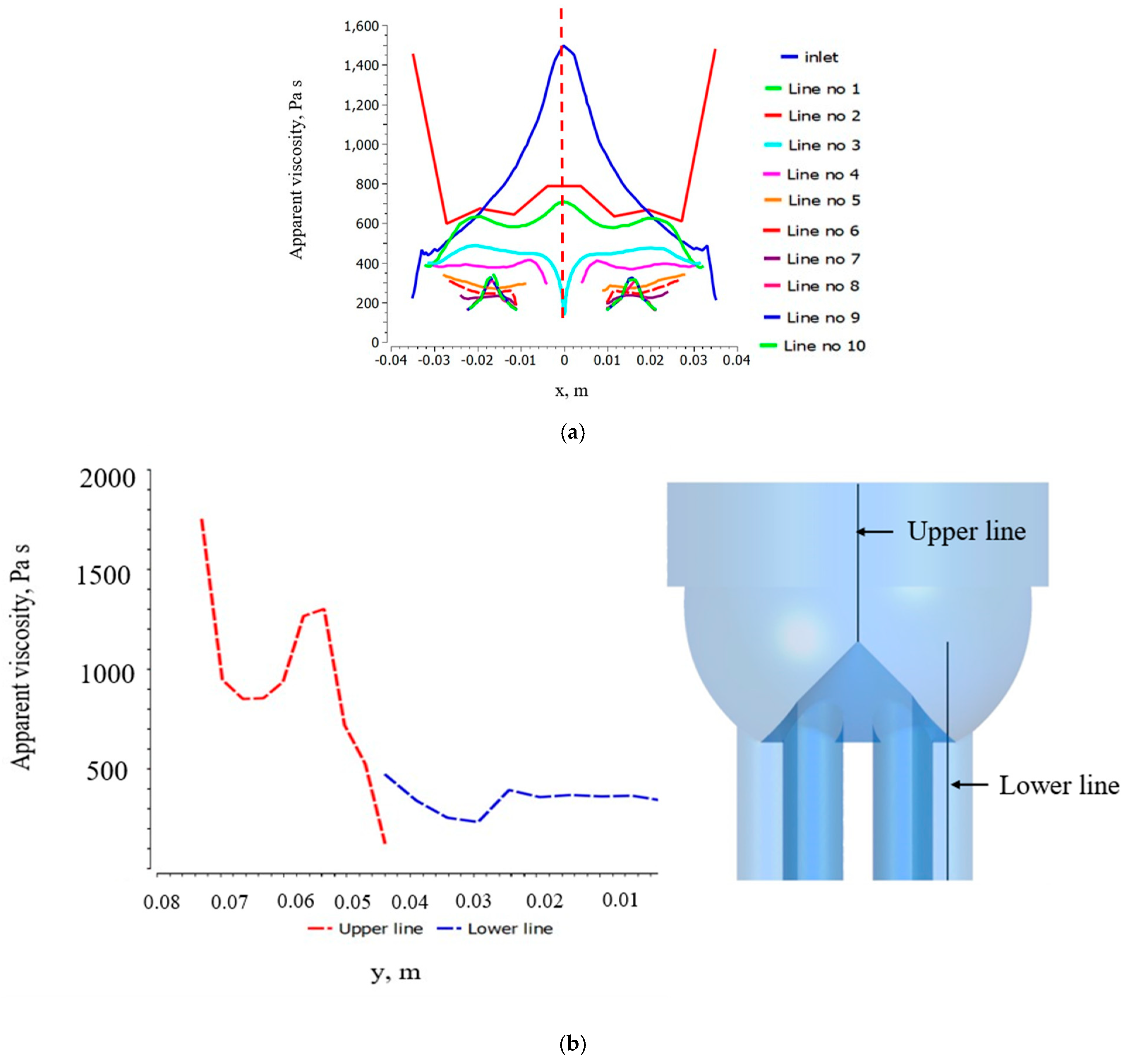
Figure 8.
Apparent viscosity variation (a) along horizontal lines and (b) along vertical lines.

Figure 9.
Wall shear at die wall for non-Newtonian fluid.
In Figure 7, the apparent viscosity changes from 1861 Pa·s to 118 Pa·s. Near the wall, the apparent viscosity is lower, while at the center, the viscosity is higher. The average viscosity at the middle of the die is approximately 1100 Pa·s. Close to the wall, the value of viscosity is approximately 200 Pa·s where the variation of apparent viscosity is approximately 80%.
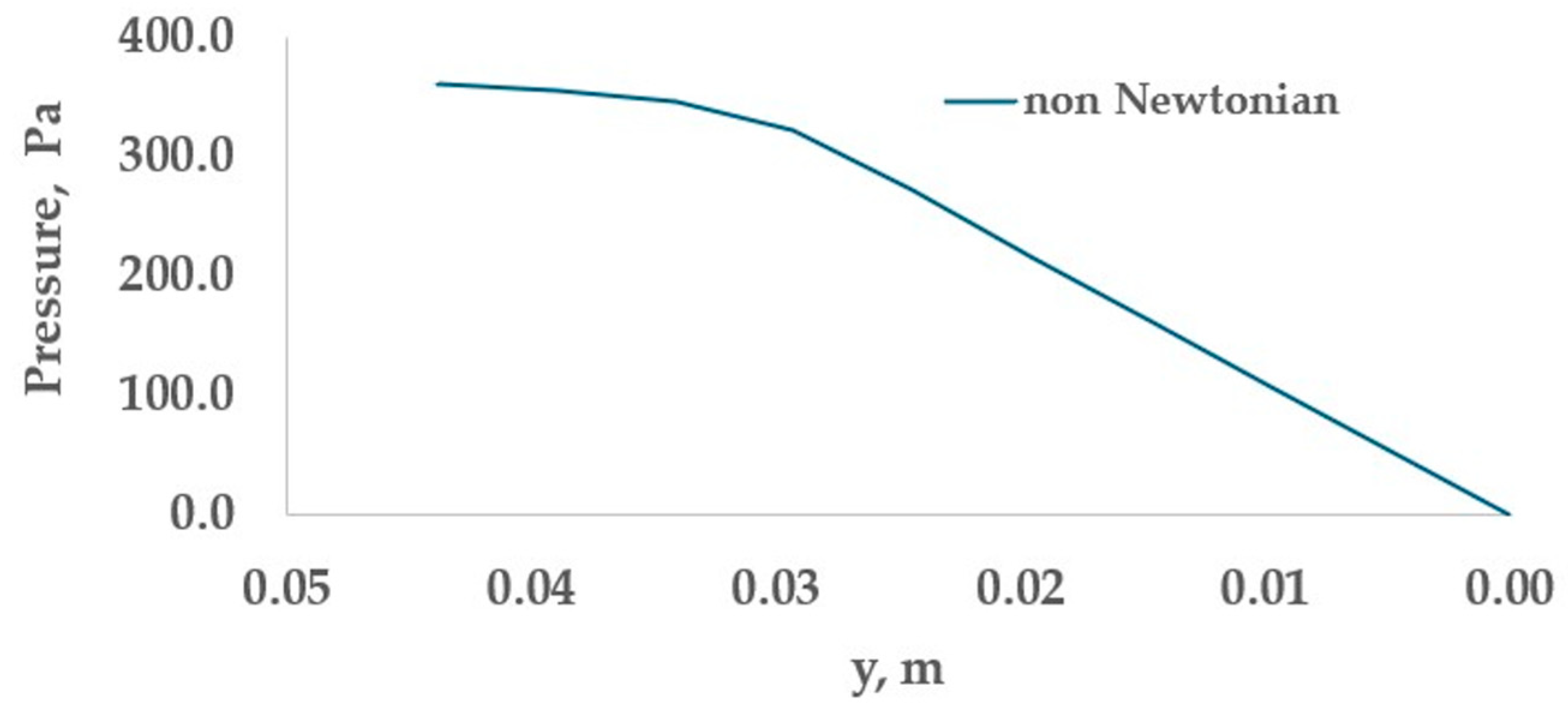
The pressure drop chiefly occurs in the outlet pipes (See Figure 3b and Figure 10). At the reservoir of the die, the pressure drop is relatively small along the flow direction.
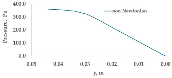
Figure 10.
Pressure drops inside the outlet pipe along the flow direction.
In Figure 10, the pressure distribution is shown inside the die along the flow direction. Within the reservoir, the pressure drop is negligible, whereas inside the outlet pipes, the pressure drop is significant.
5. Optimization of Pressure Drop by Changing the Outlet Die Angle
To reduce the needed pressure and drop in the die, a set of numerical experiments has been conducted for a range of die designs, where the exit angle of the outlet pipe varies. All remaining features of the die geometry and operating parameters remain the same as in prior sections.
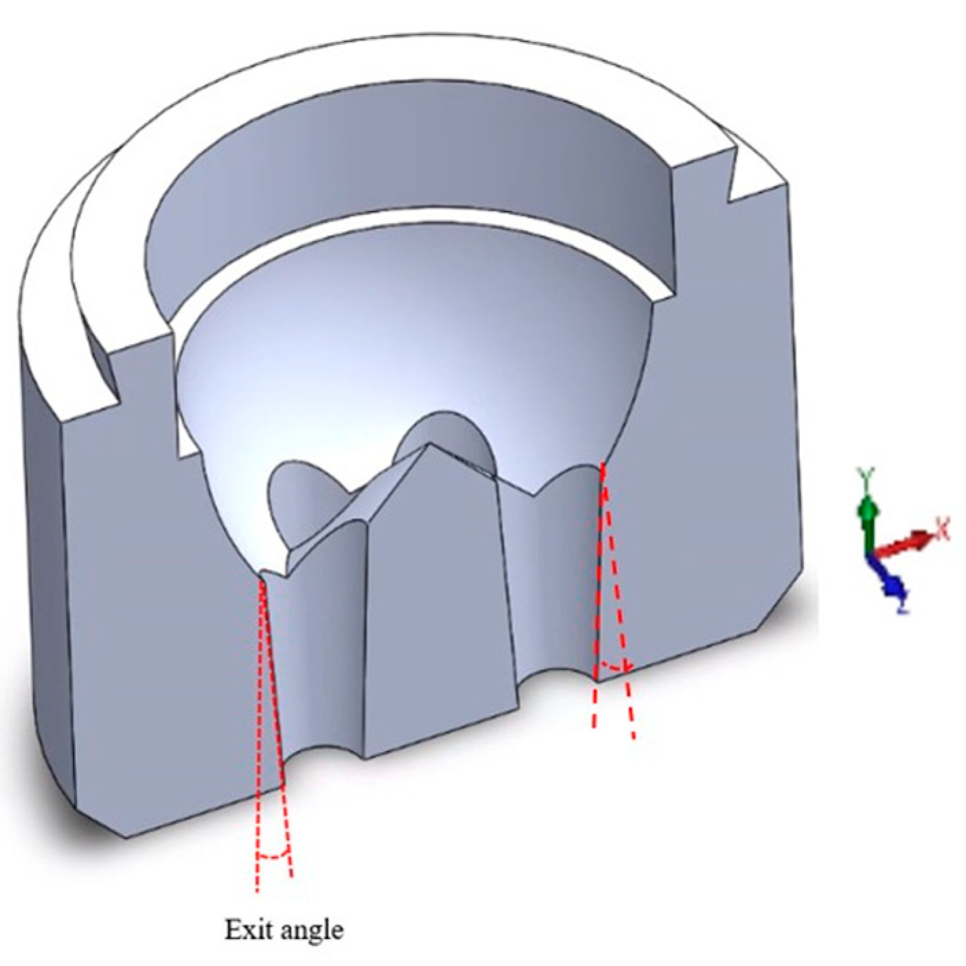
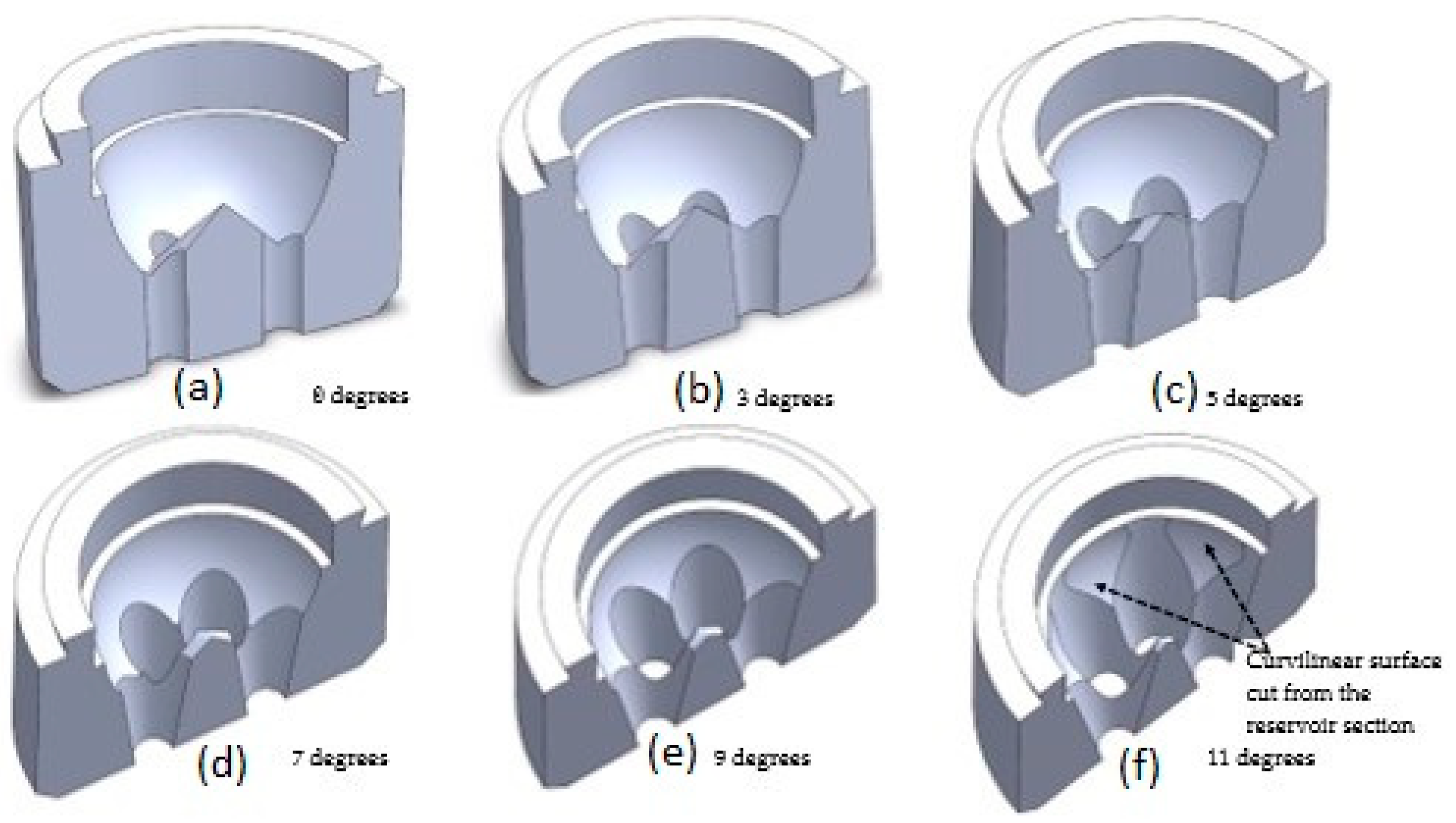
To reduce the shear stress and, consequently, the needed pressure drop, the exit angle of the die (see Figure 11) varies from zero degrees (straight exit pipe, Figure 12a) to eleven degrees (converging pipe, Figure 12f). Curvilinear surface cut from the reservoir section beyond nine degrees of the exit angle (Figure 12f).
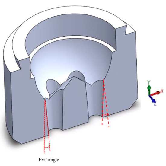
Figure 11.
Exit angle of die outlet pipe: all outlet pipes have the same exit angle.

Figure 12.
Optimization of the exit angle of the die: (a) zero degrees, (b) 3 degrees, (c) 5 degrees, (d) 7 degrees, (e) 9 degrees, and (f) 11 degrees. The angle in degrees is shown in each sub-figure.
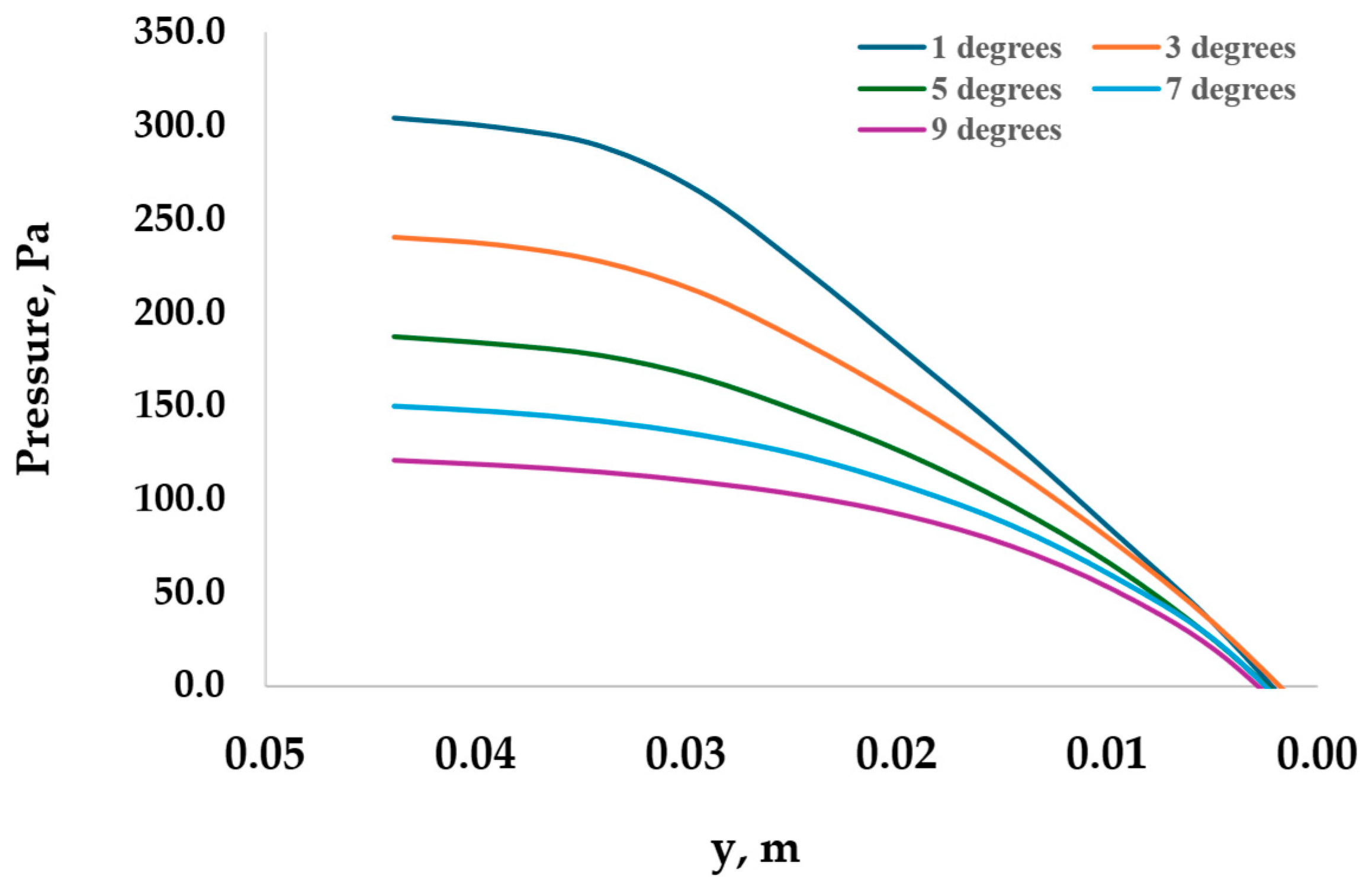
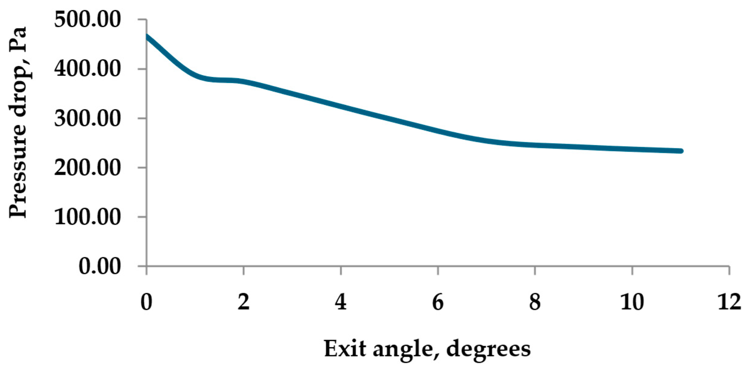
Computational results in Figure 13 and Figure 14 show that with the increase of exit angle, the pressure drop decreases significantly till the exit angle reaches 7 degrees. Though pressure drop continues to decrease at a slower rate for exit angles beyond 7 degrees, dies with higher exit angles would be difficult to manufacture. Figure 12e,f shows that exit angles of 9 and 11 degrees change the die shape, which can compromise the extrusion process.

Figure 13.
Pressure drop along the centerline of the outlet pipe.
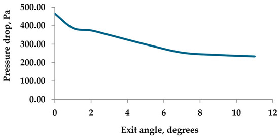
Figure 14.
Pressure drop between exit and entrance of the die at different exit angles.
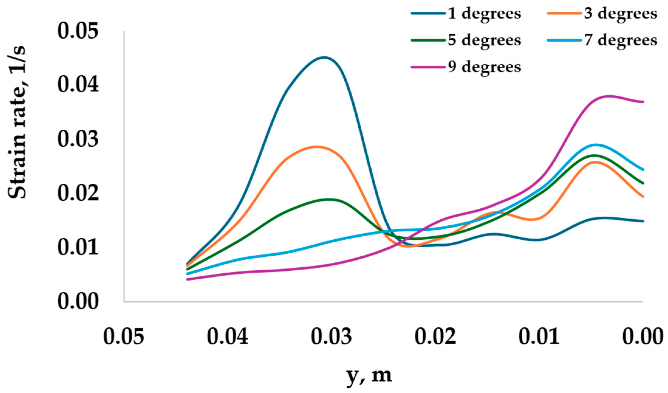
Figure 15 shows the variation of strain rate along the outlet pipe for different exit angles. At lower angles, from 1 degree to 5 degrees, there is a visible maximum and following drop of strain near the interface of the exit pipe and reservoir. Farther downstream of the interface, the strain rate increases. For larger exit angles of 7 degrees and 9 degrees, the strain rate increases gradually from the interface toward the exit of the outlet. The overall increase in strain rate is more substantial for higher exit angles compared to lower exit angles.
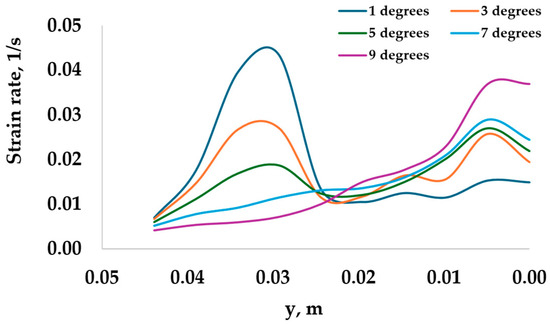
Figure 15.
Strain rate along the centerline of the exit pipe.
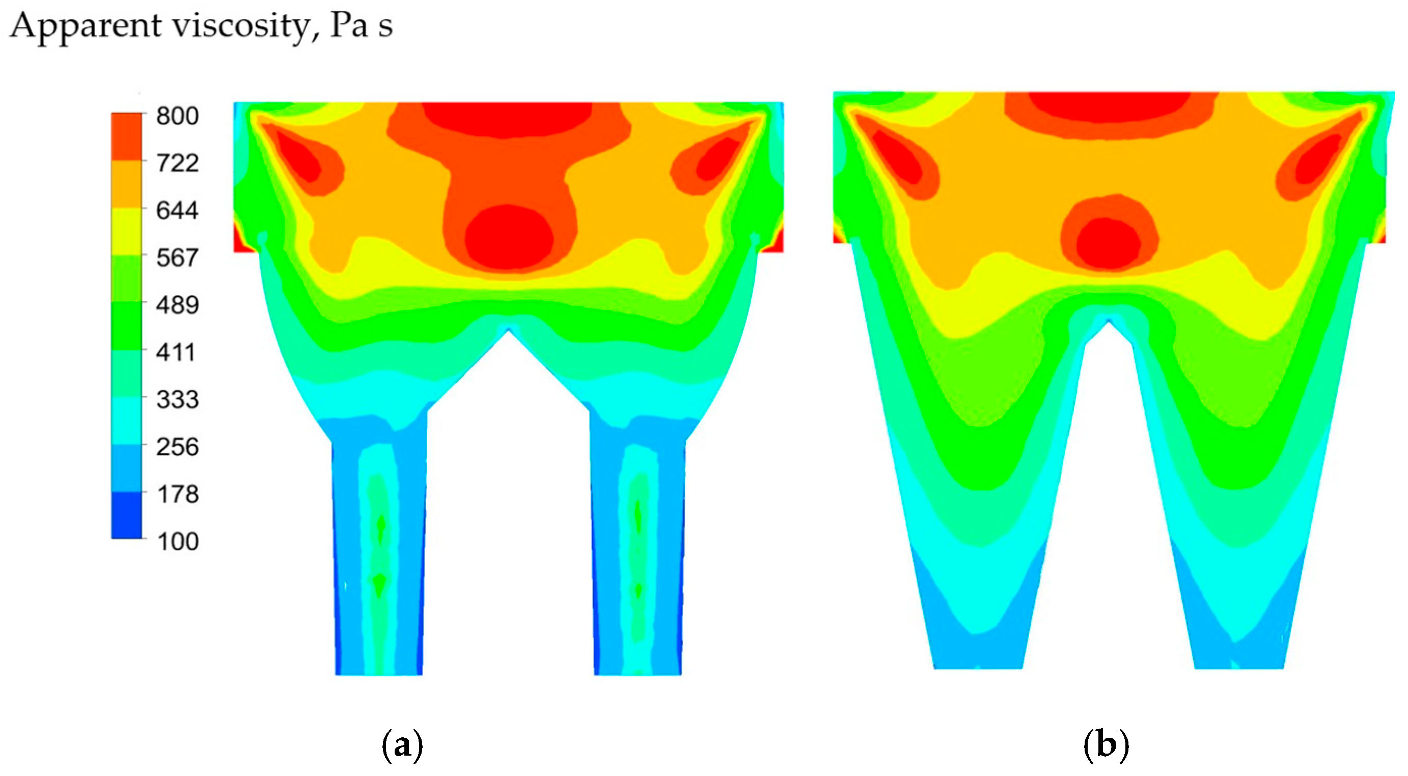
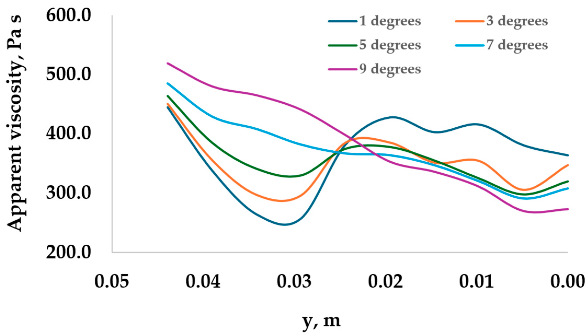
Figure 16 and Figure 17 show that with the increase of exit angle, apparent viscosity distribution changes its pattern along the outlet pipe. For smaller exit angles such as 1 degree, 3 degrees, and 5 degrees near the exit pipe entrance, there is a drop of apparent viscosity followed by its increase, while for higher angles such as 7 and 9 degrees, the apparent viscosity reduces gradually without forming the minimum. Because of the bigger shear rate (see Figure 15) and, consequently, lower apparent viscosity (see Figure 17) along the exit pipe, the corresponding pressure drop is smaller for larger exit angles.

Figure 16.
Apparent viscosity distribution at the vertical plane for the following exit angles: (a) 1 degree and (b) 11 degrees.
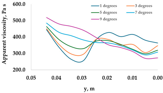
Figure 17.
Variation of apparent viscosity along the centerline of outlet pipe.
Figure 18 shows the apparent viscosity distribution in the radial direction for different horizontal planes. While at the center, viscosity is larger, near the wall, viscosity is lower. Inside the reservoir, viscosity is higher than that of the outlet. Along the flow direction, viscosity decreases.
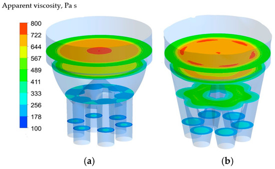
Figure 18.
Apparent viscosity distribution at different planes (at 0.1 m, 0.3 m, 0.5 m, and 0.6 m from the outlet) for (a) 1 degree and (b) 11 degree exit angles.
Figure 19 and Figure 20 show wall shear stress as a function of die exit angle. With the increase of exit angle, the shear stress at the wall decreases. This explains the dynamics of pressure drop between the exit and entrance of the die with the variation of exit angle depicted in Figure 14. Note that for the present die design, the angle is zero degrees (straight die).
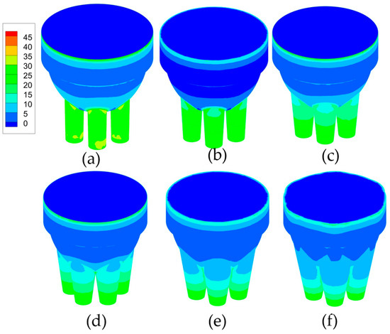
Figure 19.
Wall shear for die with exit angle (a) 1 degree, (b) 3 degrees, (c) 5 degrees, (d) 7 degrees, (e) 9 degrees and (f) 11 degrees.
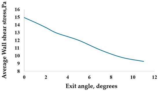
Figure 20.
Average wall shear at die wall (including reservoir and outlet pipe) for the range of die exit angles.
The new die design with converging pipes modeled in this section has a smaller pressure drop compared to the existing die.
6. Conclusions
The 3D non-Newtonian fluid flow model has been developed and implemented to optimize the die for manufacturing of energetic materials. The combination of unstructured finite-volume grid and structured grid next to solid walls of the die is adopted and used with Ansys/Fluent CFD solver.
Simulations by the developed model have been performed for the 3D die equipped with converging outflow pipes for the range of converging angles with the goal of reducing the needed pressure drop. For the new proposed die design, apparent viscosity steadily drops along the centerline of the outlet. As the apparent viscosity magnitude determines the pressure drop, the new die design with converging pipes has a smaller pressure drop compared to the current die. Though the pressure drop continuously decreases with the increase of exit angle, the rate of its change decreases for exit angles larger than 7 degrees. It is not practical to have an exit angle exceeding 7 degrees due to manufacturing difficulties, as the reservoir’s internal shape would change significantly. The exit angle of 7 degrees would ensure that the needed pressure drop is nearly halved, which would improve the performance of the extrusion die significantly.
The current study proposes a mathematical model that obtains important parameters of the extrusion process for energetic materials that are difficult and unsafe to obtain by physical experiments.
Author Contributions
Methodology, A.P.; Software, H.B.; Validation, H.B.; Writing—original draft, H.B.; Writing—review & editing, A.P.; Project administration, A.P. All authors have read and agreed to the published version of the manuscript.
Funding
The study was supported by the ARDEC Picatinny Arsenal research grant in 2016–2017, Award 8690000034.
Data Availability Statement
Data is contained within the article.
Acknowledgments
The authors thank Michael Fair (ARDEC) and Sadhan Jana (College of Polymers at the University of Akron) for their introduction to the field and discussion.
Conflicts of Interest
The authors declare no conflict of interest.
References
- Elgeti, S.N. Free-Surface Flows in Shape Optimization of Extrusion Dies. Ph.D. Dissertation, RWTH Aachen, Aachen, Germany, 2011. [Google Scholar]
- Kowalczyk, J.E.; Malik, M.; Kalyon, D.M.; Gevgilili, H.; Fair, D.F.; Mezger, M.; Fair, M. Safety in Design and Manufacturing of Extruders Used for the Continuous Processing of Energetic Formulations. J. Energetic Mater. 2007, 25, 247–271. [Google Scholar] [CrossRef]
- Malik, M.; Kalyon, D.M.; Golba, J.C. Simulation of Co-Rotating Twin Screw Extrusion Process Subject to Pressure-Dependent Wall Slip at Barrel and Screw Surfaces: 3D FEM Analysis for Combinations of Forward- and Reverse-Conveying Screw Elements. Int. Polym. Process. 2014, 29, 51–62. [Google Scholar] [CrossRef]
- Dombe, G.; Maurya, M.; Bhongale, C.; Singh, P.P.; Bhattacharya, B. Application of Twin Screw Extrusion for Continuous Processing of Energetic Materials. Cent. Eur. J. Energetic Mater. 2015, 12, 507–522. [Google Scholar]
- Mezger, M.J.; Tindle, K.J.; Pantoya, M.; Groven, L.J.; Kalyon, D.M. (Eds.) Energetics Materials: Advanced Processing Technologies for Next-Generation Materials; CRC Press: Boca Raton, FL, USA; Taylor and Francis Group: Boca Raton, FL, USA, 2017. [Google Scholar]
- Karuv, B.; Aktas, S.; He, J.; Tang, H.; Murphy, C.M.; Prickett, S.E.; Kalyon, D.M. Rheological behavior of energetic gels and suspensions. In Energetic Materials: Advanced Processing Techniques for Next-Generation Materials; Mezger, M., Tindle, K., Pantoya, M., Groven, L., Kalyon, D.M., Eds.; CRC Press: Boca Raton, FL, USA; Taylor and Francis Group: Boca Raton, FL, USA, 2017; Chapter 8; pp. 129–168. [Google Scholar]
- Kalyon, D.M.; Aktaş, S. Factors affecting the rheology and processability of highly filled suspensions. Annu. Rev. Chem. Biomol. Eng. 2014, 5, 229–254. [Google Scholar] [CrossRef] [PubMed]
- Tang, H.; Kalyon, D.M. Estimation of the Parameters of Herschel-Bulkley Fluid under Wall Slip Using a Combination of Capillary and Squeeze Flow Viscometers. Rheol. Acta 2004, 43, 80–88. [Google Scholar] [CrossRef]
- Pricci, A.; de Tullio, M.D.; Percoco, G. Semi-analytical models for non-Newtonian fluids in tapered and cylindrical ducts, applied to the extrusion-based additive manufacturing. Mater. Des. 2022, 223, 111168. [Google Scholar] [CrossRef]
- Barić, E.; Steiner, H. Flow and heat transfer of non-Newtonian fluids in enameling dies. Chem. Eng. Sci. 2015, 129, 135–144. [Google Scholar] [CrossRef]
- Ramos-De Valle, L.F. Principles of Polymer Processing. In Handbook of Polymer Synthesis, Characterization, and Processing; John Wiley & Sons, Inc.: Hoboken, NJ, USA, 2013; Chapter 23; pp. 451–461. [Google Scholar]
- Saha, P.K. Fundamentals of Extrusion. In Aluminium Extrusion Technology; ASM: Materials Park, OH, USA, 2000; Chapter 1; pp. 1–29. [Google Scholar]
- Kuang, D.C.; Shroff, R.N. Converging Flow of Polymer Melts. J. Rheol. 1981, 25, 605–617. [Google Scholar]
- Karpenko, M. Aircraft hydraulic drive energy losses and operation delay associated with the pipeline and fitting connections. Aviation 2024, 28, 1–8. [Google Scholar] [CrossRef]
- Kouzilos, G.N.; Seretis, G.V.; Provatidis, C.G.; Manolakos, D.E. Design of Polymer Extrusion Dies Using Finite Element Analysis. Section 10. In Extrusion of Metals, Polymers and Food Products; IntechOpen: London, UK, 2018. [Google Scholar] [CrossRef]
- Tadmor, Z.; Gogos, C.G. Principles of Polymer Processing, 2nd ed.; John Wiley & Sons, Inc.: Hoboken, NJ, USA, 2006. [Google Scholar]
- Drobny, J.G. Processing Methods Applicable to Thermoplastic Elastomers. In Handbook of Thermoplastic Elastomers, 2nd ed.; William Andrew: Norwich, NY, USA, 2014; pp. 33–173. [Google Scholar] [CrossRef]
- Choudhary, M.K.; Kulkarni, J.A. Modeling of Three-Dimensional Flow and Heat Transfer in Polystyrene Foam Extrusion Dies. Polym. Eng. Sci. 2008, 48, 1177–1182. [Google Scholar] [CrossRef]
- Zou, J.; Rong, B.; Liu, Y.; Rui, X.; Wang, G. Dynamics simulation and product quality consistency optimization of energetic material extrusion process. Int. J. Adv. Manuf. Technol. 2024, 131, 1497–1514. [Google Scholar] [CrossRef]
- Patankar, S. Numerical Heat Transfer and Fluid Flow; CRC Press: Boca Raton, FL, USA, 1980. [Google Scholar]
- Landau, L.D.; Lifshitz, E.M. Fluid Mechanics. In Course of Theoretical Physics; Kindle eBooks, 2012; Volume 6. [Google Scholar]
- Fox, R.W.; McDonald, A.T.; Pritchard, P.J. Introduction to Fluid Mechanics, 10th ed.; John Wiley & Sons: Hoboken, NJ, USA, 2020. [Google Scholar]
- Mezger, T.G. The Rheology Handbook: For Users of Rotational and Oscillatory Rheometers, 5th Revised ed.; Vincentz Network: Hannover, Germany, 2020. [Google Scholar]


Disclaimer/Publisher’s Note: The statements, opinions and data contained in all publications are solely those of the individual author(s) and contributor(s) and not of MDPI and/or the editor(s). MDPI and/or the editor(s) disclaim responsibility for any injury to people or property resulting from any ideas, methods, instructions or products referred to in the content. |
© 2025 by the authors. Licensee MDPI, Basel, Switzerland. This article is an open access article distributed under the terms and conditions of the Creative Commons Attribution (CC BY) license (https://creativecommons.org/licenses/by/4.0/).