Article

Advanced Design and Performance Evaluation of an Automatic Synchronized Grafting Machine for Solanum Vulgare

1
College of Electromechanical Engineering, Xinjiang Agricultural University, Urumqi 830052, China
2
Institute of Agricultural Mechanization, Xinjiang Academy of Agricultural Sciences, Urumqi 830091, China
3
Xinjiang Facility Agriculture Engineering, Equipment Technology Research Center, Urumqi 830091, China
*
Authors to whom correspondence should be addressed.
Processes 2025, 13(1), 131; https://doi.org/10.3390/pr13010131
Submission received: 22 November 2024 / Revised: 30 December 2024 / Accepted: 31 December 2024 / Published: 6 January 2025
(This article belongs to the Special Issue Reliability and Engineering Applications (Volume II))

Abstract

:
The adoption of grafting machines has become an essential trend in the advancement of the vegetable nursery industry, driven by the aging population and the rapid growth of the vegetable sector. Domestic and foreign research organizations have designed various types of vegetable grafting devices for the huge nursery market. However, most of the machines developed and designed at home and abroad are now semi-automated and are thus highly susceptible to damaging the stems of the seedlings during operation. Therefore, in order to realize the complete automation of the grafting operation and improve the grafting survival rate and quality, in this paper, eggplant hole tray seedlings were grafted as the object, and the cutting mechanism, the integrated mechanism of clamping and fitting, and the wrapping mechanism were structured on the basis of the affixing method. The transition conversion from semi-automatic to fully automatic was realized. And the rationality of the design was verified via the cutting test and the clamping characteristic test, which maximized the fit rate between the cutting surface of the rootstock and the scion seedling and maximized the protection of the grafted seedling from damage in the clamping process. Finally, the device was tested using Torubam rootstock and a Nova 101 tomato scion. The results showed that the optimal cutting angles were 35° and 30° for rootstock and scion, respectively, and that the lengths of the cutting surfaces were 11.28 ± 0.18 mm and 11.43 ± 0.14 mm. The grafting efficiency of the machine was up to 700 grafts per hour, with an average grafting success rate of up to 95% and zero stem damage to the seedlings. The experiments proved that the structure design of the machine is reasonable, and it can fully improve the grafting efficiency and quality. Meanwhile, the research findings can provide a theoretical basis for the application of the latter in the field of plant grafting. The research results can effectively alleviate the dependence on manual labor in the nursery industry and further liberate the labor force.

1. Introduction

China is the world’s largest producer and consumer of vegetables, and vegetables have become the second largest crop in the plantation industry after grain [1,2]. Continuous cropping is becoming increasingly common due to the shortage of available land and the vegetable industry’s rapid growth [3]. The soil degradation brought on by continuous long-term farming has made native seedling drawbacks more apparent over time. Problems such as a long growth cycle and the poor resistance of native seedlings constrain the quality and yield of the vegetable industry [4,5]. The effects of continuous vegetable cultivation can be effectively mitigated by grafting seedlings [6,7,8,9,10]. Traditional manual grafting is time-consuming and labor-intensive. Manual grafting can no longer meet the needs of standardized and mass production at this stage. So, the key production link mechanization operation has become an inevitable trend in the development of the vegetable seedling industry [11,12].
Since the 1980s, foreign agriculture machinery enterprises and research units have undertaken technical research on vegetable grafting devices. Various types of grafting machines have been developed based on different grafting methods [13,14,15]. In 1994, the Nippon Yanmar Corporation developed the AG1000 fully automatic grafting machine for eggplant and fruit [16]. This machine requires a high level of standardization in seedling cultivation because of the whole tray operation. The matching of rootstock and scion seedling stem size directly affects the grafting quality, resulting in only four sales of the machine since its release. In 2005, South Korea’s Ideal system company developed a flat grafting automatic grafting machine. The machine uses pentagonal ceramic pins to hold rootstocks and scions and has a productivity of 1,200 plants per hour [17]. Due to the use of the flat grafting method, the machine struggles to control the tightness of the incision fit and has not yet been used in practical production applications. The Netherlands is the world’s most advanced country in terms of the development of facility horticulture automation and intelligence. The ISO Group developed the Graft1000 casing grafting machine using image processing technology in the grafting of unqualified seedlings in pre-seedling culling. In use, it was found that the machine required strict control of the age of the seedlings, required the frequent replacement of parts during production, and was difficult to use in mills with low standardization [18]. In 2009, the Tea Project (Italy) developed GRAFT1000 spray grafting, which uses a special adhesive to quickly glue the cuts and wrap them around the stems of the seedlings, completing a grafted seedling in just 4 s. However, it requires two operators to graft the seedling, and the cost of a grafted seedling is about 0.2 euros, which makes the grafting cost too high.
China’s vegetable grafting robot development came later than those of South Korea, Japan, the Netherlands, and other countries However, starting in the 1990s, after nearly 30 years of development, China also made great progress in the field of vegetable grafting facilities [19,20]. The team of Prof. Zhang Tiezhong from China Agricultural University, the team of the Beijing Agricultural Intelligent Equipment Technology Research Center, and the team of Prof. Li Jianping from Zhejiang University have all developed different types of grafting devices [21,22,23,24,25,26]. Influenced by nursery budgets and nursery patterns, most of the machines developed so far at home and abroad are semi-automatic-type models with manual seedling loading, although the basic models can complete the main grafting operations [27,28,29,30,31]. However, research on the protection mechanism of seedlings is shallow, and the phenomenon of seedling injury often occurs in the grafting process [32,33,34,35]. Therefore, in this paper, in order to essentially improve the adaptability of the clamping mechanism to seedlings and the quality of affixing, the key mechanism was structured. At the same time, mechanistic research on the cutting angle of seedlings, the affixing degree, seedling injury, and other aspects was carried out. Fully automatic synchronized grafting equipment for eggplant and fruit was designed. This machine is designed as a fully automatic and synchronized grafting machine for eggplant and fruit with eggplant family vegetable hole tray seedlings as grafting objects [36]. While realizing full automation, it ensures the grafting quality and success rate. This has opened the last kilometer from semi-automatic grafting to intelligent grafting operation.

2. Materials and Methods

2.1. Overall Design of the Grafting Machine

Facility agriculture in China has rapidly expanded, now covering 2.67 million hectares [37]. With its rapid expansion, grafting has become the most commonly used seedling technology. However, most seedling factories in China still rely on manual grafting, which is labor-intensive and inefficient, especially given the seasonal nature of vegetable production [38]. This inefficiency arises from the low level of automation in vegetable grafting facilities, where manual seedling feeding is still required, preventing the realization of fully automated grafting. Consequently, the efficiency of current grafting methods remains comparable to that of manual operations. In order to address these challenges and fully automate the process for pica-type eggplant fruit, we developed a specialized grafting machine. This machine employs a one-way, four-channel paste grafting system and integrates several key components, including a tray conveying and positioning mechanism, a seedling feeding mechanism, a seedling topping mechanism, a precision patching mechanism, a synchronous cutting mechanism, a bandage mechanism, and a finished seedling coding disc mechanism. These features work in harmony to achieve efficient, automated grafting, as shown in Figure 1, which illustrates the overall design scheme of the 3D model of the eggplant automation grafting device.
The overall structure of the machine includes a rootstock and scion conveying and positioning mechanism, as well as a clamping seedling loading mechanism at both ends. These seedling loading and palletizing mechanisms are installed on both sides of the table, with the seedling loading mechanism positioned above the conveying and positioning mechanism. At the inner 90° position, a cutting mechanism is installed, while the center of the machine features a single-stroke four-channel clamping and splicing mechanism. At the back of the workbench, a bandaging station is set up. In order to improve the efficiency of grafting, this machine is designed for synchronous seedling cutting, precise grafting, and reliable clamping and wrapping operations. According to the position of the spindle, the machine operates with four groups of channels. The workflow proceeds as follows: once a group of rootstock scion seedling completes the seedling operation, the spindle rotates to drive the group of grafted seedling into the cutting station. After the completion of the cutting, the spindle rotates again to position the splicing mechanism for bandaging. Following the bandaging process, the spindle rotates once more to drive the finished seedling to enter the yard plate station. This cycle is repeated across the four groups of channels to achieve continuous, high-speed grafting. This machine enables high-speed grafting operation and improves grafting production efficiency.

2.2. Structural Design of Cutting Mechanism

The design of the cutting device is one of the most critical aspects of the whole grafting device. The ability to securely attach the grafted rootstock and scion seedlings depends on the precise matching of the cutting angle. The quality of cutting directly affects the quality of attachment, which is the key to guaranteeing grafting success and the survival rate of seedlings. In this section, the cutting mechanisms of the rootstock and scion are analyzed by both theoretical and experimental methods. A device is designed to cut the rootstock and scion synchronously, and the optimal operating parameters are determined.

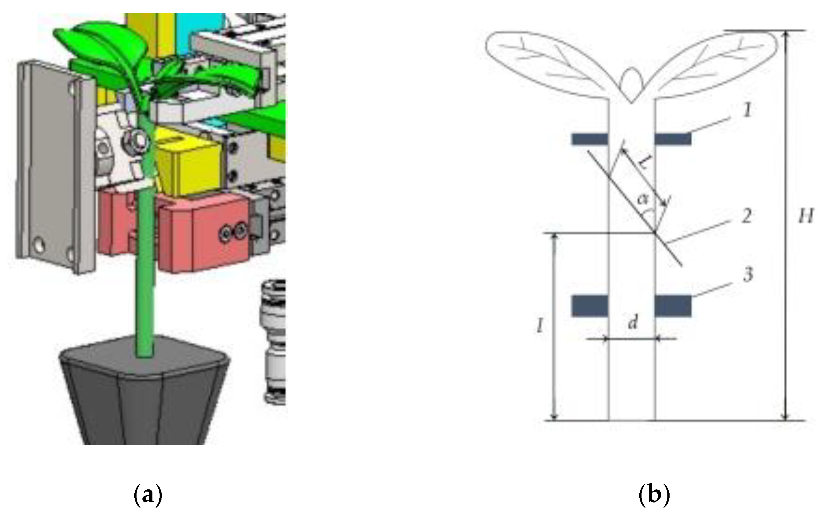
2.2.1. Mechanistic Study of Cutting Angle

The cutting mechanism forms the foundation for achieving high-precision and secure grafting, and serves as the theoretical basis for the design of the cutting mechanism and parameter optimization. Currently, most of the existing grafting devices, both domestically and internationally, utilize the affixed grafting method, which can be categorized into two approaches: the flat cutting method and the oblique cutting method [39,40]. In the flat cutting method, the cutting tool operates at 90° perpendicular to the stalk. This approach features a simple structure and high maneuverability. However, the contact surface formed between the two stems after cutting is small, increasing the possibility of insufficient adhesion and thereby affecting the survival rate of grafting. In contrast, as illustrated in Figure 2a, the diagonal cut method employs a cutting tool with an inclination angle ranging from 20° to 45°. This inclination produces an elliptical contact area on the cutting surface, which is larger than that achieved by the flat cutting method, which is more conducive to the survival of grafted seedlings. According to the design requirements of the grafting device in this study, the cutting device of the grafting equipment is designed by the oblique cutting method, and the optimal cutting parameters are determined through experimentation.
Figure 2b shows the positional relationship between the cutting tool and the seedling stem in the cutting operation. For the scion cutting, the cut must be made 70–90 mm above the substrate to form a wedge-shaped cut. This positioning ensures the cut is centered between the first step and the second step of the position. The cutting angle, denoted as α, is defined as the angle between the cutting surface and the vertical direction. Typically, the cutting angle α ranges from 20° to 45°. A smaller cutting angle α results in a larger cutting area, which theoretically increases the adhering surface area and improves the survival rate of the grated seedlings. However, if the cutting angle is too small, the docking area of the scion seedling becomes too weak to withstand the pressure of subsequent grafting processes such as clamping and fixation. This can lead to damage to the seedling stem. Thus, it is particularly important to determine the precise cutting angle. According to the theoretical analysis of the cutting process [41], the following formula is established:
The length of the cut long axis of the rootstock is
L 1 = d s i n α 1
The length of the long axis of the cut surface of the scion is
L 2 = d s i n α 2
After the oblique cutting of the rootstock and scion, the cut surface forms an ellipse. When the cut surfaces are affixed, the affixed surface is more complicated, making it challenging to calculate the cut surface affixation rate. To simplify the calculation process, the cut surface affixation rate of the grafted seedling is reflected by the ratio of the length of the long axis of the cut surface of the rootstock and scion, adjusted for the degree of alignment based on the cutting angle.
The cut surface fit rate formula is
K = L 1 L 2 × 100 %
In the formula, K is the scion and the rootstock cutting fit rate (%); L1 is the length of the long axis of the scion cut surface, mm; and L2 is the length of the long axis of the rootstock cut surface, mm.
According to the morphological characteristics and geometric parameters of the grafted seedlings observed in previous tests, it was determined that the Torubam dual-purpose grafting rootstock and Nova 101 tomato scion, when grafted, have a stem diameter similar to that of tomato seedlings. The cutting angle can be adjusted to control the fit rate of rootstock and scion cutting surfaces. Tests were conducted by changing the cutting tool’s tilt angle to 20°, 25°, 30°, 35°, 40°, and 45°. The experiment was conducted in six groups, with each group testing 20 rootstock seedlings and 20 scion seedlings. The test results are summarized in Table 1.
According to the grafting process requirements of lycopene vegetables [42], in order to ensure the survival rate of seedlings after grafting, the difference between the stem thickness of the rootstock and scion must be within 1.0 mm. The cutting angle should be kept between 25° and 40°, and the effective length of the beveled surface must not be less than 8 mm. From the data in Table 1, it can be observed that the length of the beveled surface decreases as the cutting angle increases. When the cutting angle is 20°, the length of the beveled surface of Torubam tomato rootstock seedlings and Nova 101 tomato scion seedlings is 16.49 ± 0.21 mm and 14.12 ± 0.18 mm, respectively. Although the scion- and rootstock-adhering surface can be maximized at this point, the cutting angle is too small, resulting in a weak incision that cannot withstand the subsequent pressure from grafting clamps, resulting in pressure injuries. When the cutting angle exceeds 45°, the length of the beveled surface of the two seedlings falls below 8 mm, and the effective adherence surface becomes too short to support the survival of grafted seedlings. After analysis, it was determined that the cutting angle should be controlled between 25° and 35°. At this range, the beveled surface is between 13.35 ± 0.14 mm and 8.42 ± 0.12 mm, which meets the requirements of the grafting process. Based on the fitting rate formula calculated above, the beveled surface is 11.43 ± 0.14 mm, when the scion cutting angle is 30°, and the length of the beveled surface is 11.28 ± 0.18 mm, when the rootstock cutting angle of 35°. At this point, the fitting rate of the beveled surface of the two seedlings reaches its maximum value of 98.3%, which meets both the design and process requirements. The subsequent design and debugging of the cutting equipment is carried out based on these data.

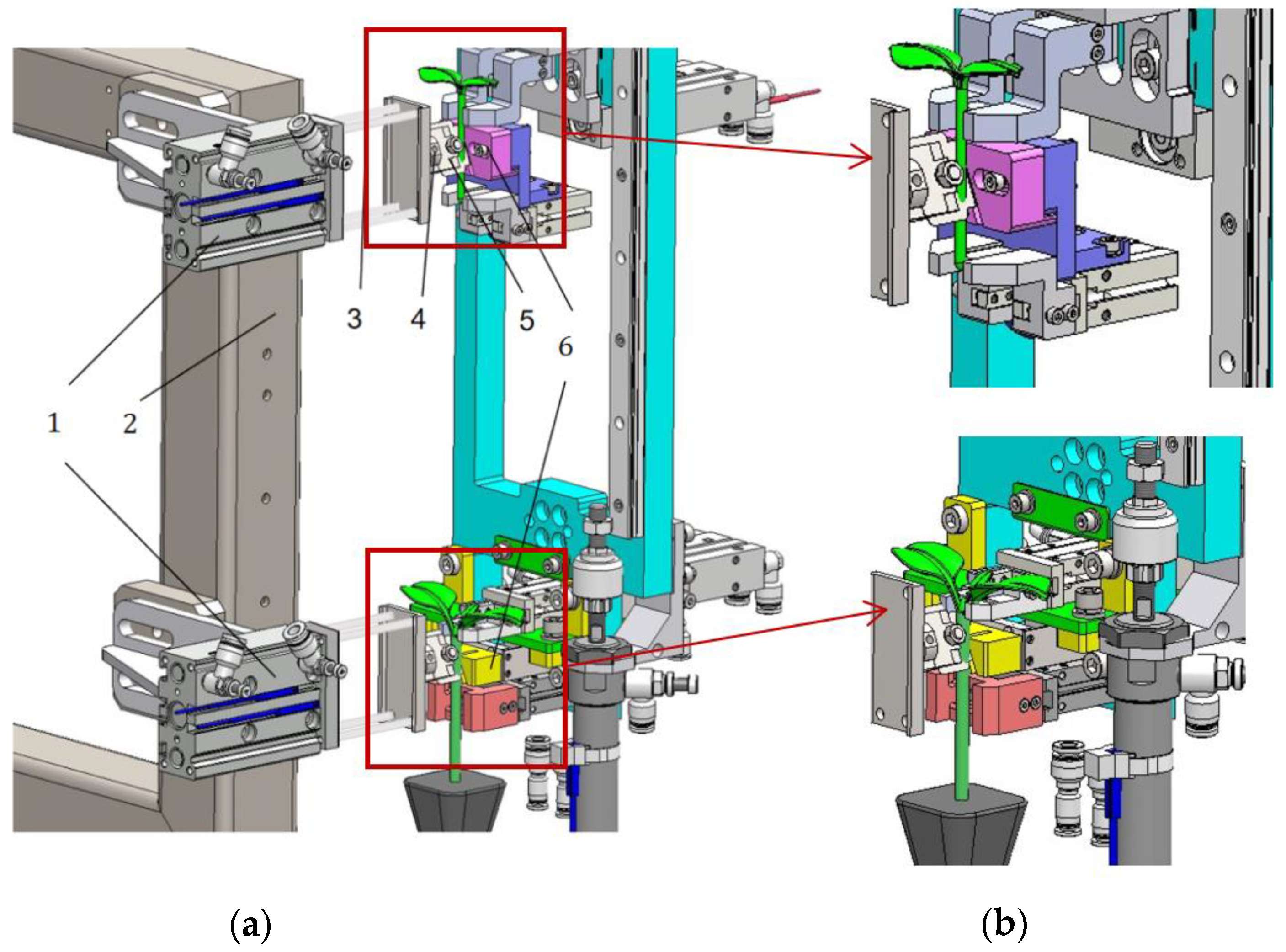
2.2.2. Mechanized Structural Design

In order to solve the influence of scion seedling stem cutting accuracy on the deviation of attachment, this study designed a two-bladed position-synchronized cutting mechanism, as shown in Figure 3a. The cutting blades are mounted on two fixed knife holders and are driven by two push rod cylinders, which serve as the power source to synchronize the cutting of the rootstock and scion seedlings. The cutting mechanism consists of push rod cylinders, fixed knife holders, two sets of cutting blades, and knife blocks. According to the requirements of the rootstock and scion affixing and wrapping process, the scion cutting pusher cylinder is installed above the rootstock cutting pusher cylinder. One end of the knife frame is fixed on the pusher cylinder, while the other end is designed with an adjusted tilted surface and regulated screws to control the cutting angle of the blades on the seedling stems. In order to prevent the stem deformation caused by the force during the cutting operation, which could result in a deviation in the cutting angle, two sets of letting knife blocks are placed between the upper and lower clamping jaws of the rootstock and scion. The knife blocks were installed in the anvil scion of the lower clamping claw and anvil on the clamping claw. These knife blocks are assembled from two trapezoidal file blocks, which are adjusted via bolts. The function of the knife block is to clamp seedling stems at the center, preventing cutting tampering and ensuring proper cutting formation. The center of the knife block is equipped with an inclined knife slot. The distance between the two trapezoidal blocks can be adjusted through the adjusting bolt, allowing control over the size of the knife slot.
At the front of the cutting mechanism, an anvil and scion clamping mechanism are equipped. The clamping mechanism is composed of the upper and lower halves of the clamping claw. It fixes the grafted seedling by forcing the clamping claws to contract with the clamping cylinder. Afterward, the cutting cylinder activates the gas cutter, and at the same time, the anvil and the scion are cut and molded. Following the cutting operation, the cutting tool is subsequently retrieved, as shown in Figure 3b. Once cutting is completed, the upper part of the anvil clamping jaws and the lower part of the scion clamping jaws open. After cutting, the lower part of the scion and the upper part of the anvil waste fall into the waste collector below.

2.3. Design of the Integrated Clamping and Laminating Mechanism

2.3.1. Selection of Elastic Shims for Clamping Fingers

To address the clamping damage and cutting tampering caused by rootstock and scion stalks in the clamping process [43], this paper proposes an elastic clamping method based on buffer material. The elastic spacer with elasticity is attached to the inner surface of the upper clamping finger of the scion and the lower clamping finger of the rootstock. The clamping principle is shown in Appendix A, Figure A1a. When the clamping finger is closed, the contact surface of the elastic spacer and the grafted seedling stalk forms an indented stalk surface. The clamping force applied to the grafted seedling can be controlled by adjusting the distance between the two elastic spacers. This clamping force is also influenced by the material’s hardness, thickness, and compression deformation. Therefore, selecting the appropriate elastic spacer is crucial to ensuring that the clamping finger does not damage the seedling.
According to the contact requirement that the seedling stalks should be clamped firmly without causing damage during the clamping process, four types of non-linear tangent elastic materials were selected for the elastic pads, as shown in Appendix A, Figure A1b. These four types of elastic pads are, in order, a high-elastic rubber shock-absorbing cushion, a 38-degree EVA polystyrene foam buffer cushion, a high-density xps polystyrene extruded soft cushion, and a modified polyurethane particle shock-absorbing cushion.
The relationship between the force and deformation in elastic materials is
F = 2 K d π t a n π x 2 d
In the formula, K is the initial elasticity coefficient and d is deformation limit of elastic material.
The optimal material is determined through testing; the buffer shims for the elastic clamping finger and four groups of 20 pieces of elastic shims with a size of 30 mm × 30 mm × 6 mm and a rigid iron rod with a diameter of 6 mm were selected, respectively. The test was divided into 10 groups, with two shims of the same type randomly stacked flat. The iron rod was placed in the middle of the elastic gasket, and the pressure was applied using a universal material testing machine. The displacement of the compression head was measured at 2 mm, 4 mm, 5 mm, and 6 mm, and the gasket deformation was recorded. Using a formula, the average pressure exerted on the rigid iron rod at these displacements was calculated. The test data were then organized, and the results are shown in Table 2.
According to the grafting agronomic technical requirements, the elastic limit for the safety clamping force of common eggplant and fruit grafted seedlings is 6–8 N. An analysis of the data in Table 2 shows that when the compression amount exceeds 5 mm, the pressure exerted by the high-elasticity rubber shock-absorbing pads, the high-density xps polystyrene extruded soft cushion, and the polyurethane granular shock absorbing pads on the rigid iron rod is greater than or equal to the safety clamping force required for eggplant and fruit grafted seedlings. This indicates that the use of the three materials as elastic clamping finger pads would likely damage young seedlings. Only the 38-degree EVA polystyrene foam remained below the safe clamping force of the seedlings during the test and did not cause damage to the crop. Therefore, the use of 38-degree EVA polystyrene foam as a finger gripper is considered safe and reliable.

2.3.2. Structural Design of the Clamping Jaws

In order to meet the clamping requirements of the four-station sequential fixing, cutting, splicing, and yard plate of eggplant and fruit automated grafting, this section designs rootstock scion clamping grips, with the structural schematic diagram shown in Figure 4a. The clamping mechanism mainly consists of anvil clamping jaws, scion clamping jaws, a mounting plate, scion clamping jaws by the upper jaws, lower jaws, clamping cylinders, a knife block, and a telescopic cylinder under the jaws. The anvil clamping mechanism consists of the upper clamping claw, lower clamping claw, clamping claw clamping cylinder, knife block, and a telescopic cylinder mounted on the anvil clamping claws. Each clamping claw consists of two left and right movable elastic clamping fingers and an EVA elastic spacer. The left and right clamping fingers are mounted on the clamping cylinder, while the scion on the clamping claw cylinder is mounted on the liftable mounting plate. The left and right clamping fingers are controlled by the switching cylinder to open and close. The EVA elastic spacer is affixed to the inner surfaces of the clamping fingers, and the grafted seedling stems are fixed by the EVA elastic spacer. The outer side of the clamping fingers is equipped with a clamping distance-adjusting bolt, which is used to adjust the clamping distance between the left and right clamping fingers, thereby controlling the covering depth of the grafted seedling in the EVA elastic gasket.
The rotation of the rotary mechanism in the seedling clamping jaw rotary feed cylinder is detected by the magnetic switch, which senses the delivery of seedlings. The clamping mechanism, driven by the cylinder, moves the left and right elastic clamping fingers laterally to clamp the seedlings. After the seedlings reach the clamping position, the upper and lower clamping jaw clamping cylinders synchronized their transverse movement to complete the clamping and fixation of the rootstock and scion seedlings. After the attachment process is completed, the cutting knife retracts and the magnetic switch in the cutting mechanism senses the knife retraction. The lower clamping claw of the scion and the knife block are connected, and under the drive of the telescopic cylinder, the upper clamping claw of the anvil and lower clamping claw of the scion, along with the knife block, retract in the opposite direction to avoid interference with the scion’s longitudinal downward movement in the splicing process.

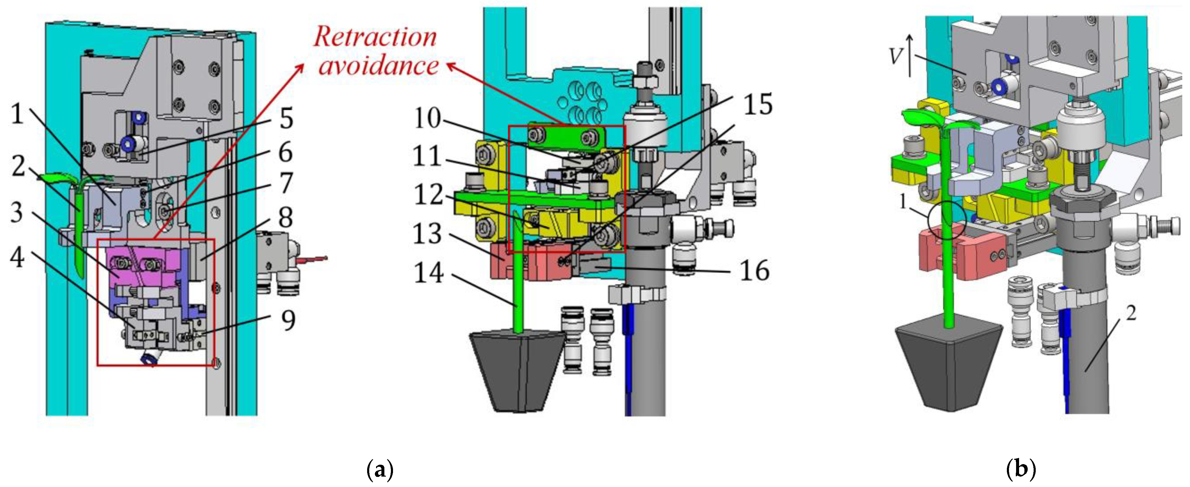
2.3.3. Structural Design of the Attachment Mechanism

Based on the clamping and cutting mechanism designed in this study [44], a vertical longitudinal lift and affixing mechanism was designed, as shown in Figure 4. The upper clamping jaw mounting plate of the scion is vertically mounted with a single-axis actuator cylinder and an upper clamping jaw lifting rail. After the grafting seedling cutting process is completed, the cutter retracts and the magnetic switch mounted on the cutting mechanism senses the retraction of the cutter. The scion’s lower jaw is clamped and connected to the knife block, and under the drive of the telescopic cylinder, the anvil’s upper jaw and scion’s lower jaw, along with the knife block, retract in the opposite direction to the seedling, as shown in Figure 4a. This retraction prevents the scion’s longitudinal downward movement in the splicing process.
The magnetic switch mounted on the clamping jaw telescopic cylinder senses the clamping jaws to avoid retraction, allowing the grafted seedlings to enter the affixing process; the single-axis pusher affixing cylinder supplies air to drive the scion on the clamping jaws, which perform a vertical top-down action to clamp the semi-finished scion seedling. The scion jaws carry the scion seedling, and the anvil under the clamping jaws clamps the anvil seedling to affix them together, as shown in Figure 4b, which illustrates the effect of the scion seedling affixed to the anvil. In traditional grafting machines, the affixing bandage requires the seedling clamping to be carried to a new station before the affixing operation. However, in this device, after the cutting operation is completed, the affixing operation is directly carried out in the original station. The affixing process is completed by vertically dropping the scion onto the jaws, where it is then docked with the anvil seedling. The use of this new type of lifting and lowering splicing mechanism avoids the need for handling the splicing angle, reducing unnecessary displacement and thereby improving the accuracy of the splicing surface.

2.4. Design of the Clamping and Wrapping Mechanism

The automatic clamping device is a crucial component of automatic grafting equipment for eggplant and fruit species. Its primary function is to tightly fix the rootstock and scion seedlings, which have been joined using grafting clamps, after the synchronized cutting and precise attaching are completed. This step is critical, as the success rate of the grafted seedlings depends heavily on the effectiveness of this mechanism. In this section, a novel automatic clamping mechanism is designed based on the mechanical tests of the grafting clamp, which consists of two parts: a continuous clamping mechanism and a push-up clamping mechanism.

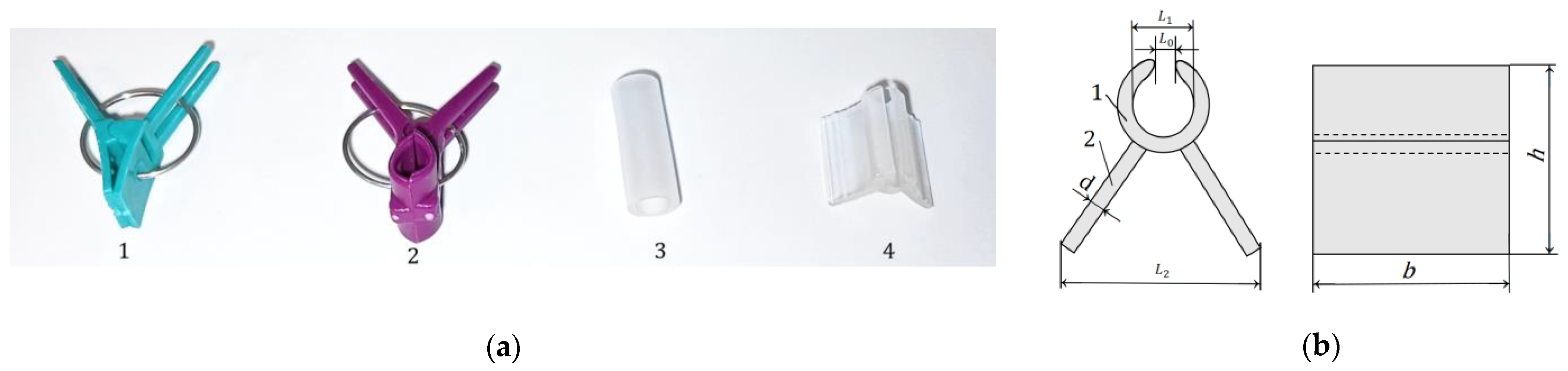
2.4.1. Mechanistic Studies of Grafting Clamps

  • Selection of Grafting Clips
Grafting clamps are essential components of grafting operations, playing a key role in ensuring the robust growth of grafted seedlings through tight fixation [45]. In order to ensure a high survival rate for grafted seedlings, it is necessary to carry out correlation studies between the grafting clamp and its clamping mechanical properties. The clamping force of the grafting clamp should be carefully chosen to stay within the safety limits that grafted seedlings can withstand. If the clamping force is too high, this can cause secondary damage to the seedlings. Conversely, if the clamping force is too low, the grafted seedlings are prone to detachment during automatic handling, such as when transferring them to a handling tray. Therefore, the appropriate selection of grafting clamps is particularly important for the entire grafting operation. Commonly used grafting clamps for agronomic operations are shown in Figure 5a.
As shown in Figure 5a, four types of grafting clamps are commonly used. No.1 is the most widely used steel coil spring clamp, with a split structure of the head and tail, which is a cheap and simple structure, and the clamping force is controlled by the steel coil spring. However, this type of grafting clamp requires pairing with a pulsed vibration disc clamping device, making it prone to clamping injury and clogging of clamping during the operation. No.2 grafting clamp is a large-scale opening clamp used for hand grafting, typically for large seedlings such as watermelon and squash. Its large mouth opening and high clamping force make it unsuitable for the mechanized grafting of melon and Solanaceae crops, which generally involve younger seedlings. No.3 is a cannula grafting clip, featuring a simple casing that does not cause secondary damage to the grafted seedling stem. It eliminates the need for manual removal after grafting, as the casing naturally detaches with plant growth. However, the application of this type of casing is cumbersome, and the success rate of mechanical installation is low. No.4 is a PE polyethylene rubber–plastic grafting clip, with the head and tail molded as a single structure. This clip offers high softness and elasticity, is lightweight, and does not damage the seedling stem. The clip can be supplied in trays, and the research design of the continuous supply mechanism allows adjustments to fit the cutting size of the rootstock and scion. In this study, No.4 PE polyethylene rubber grafting clips were selected for the clamping device in the grafting equipment.
No.4 grafting clamp is a grafting clamp made of PE polyethylene rubber–plastic material injection-molded in one piece, as shown in Figure 5b. The grafting clamp mouth of this material has a certain preloading force. During the working process, the clamping finger of the push-up clamping mechanism exerts pressure on the clamping handle of the grafting clamp, causing the clamping mouth of the grafting clamp to overcome the preloading pressure and open. The stepping motor of the push-up clamping mechanism then moves the open grafting clamp to the adherence surface of the rootstock and scion. Once the clamping finger releases the pressure, the grafting clamp closes up, securing the grafted seedling and completing the wrapping process. The clamping force of the grafting clamp has a great influence on the survival of grafted seedlings. In order to support the mechanics test of the grafting clamp, the various measurement parameters are shown in Table 3.
2.
Verification of the Safety of PE Polyethylene Rubberized Butterfly Clips
The clamp body is divided into two parts: the clamp handle and the clamp mouth, both of which are molded as a single piece. The force analysis of the clamp mouth when open and the clamp handle under compression is shown in Figure 6a. Assuming that the clamping handle is a rigid structure, no deformation occurs as the compression force is applied. The tension at the mouth of the clamp increases as the compression displacement grows. According to the data of the morphological test of the rootstock scion seedlings in Section 2, the stem thickness of the rootstock and the scion is about 5.6 mm and 4.8 mm, respectively. Therefore, the study investigates the clamping force released by the grafting clamp on the stem when the clamping mouth diameter L1 is about 6 mm. The elastic limit values of the rootstock scion seedling, approximately 5.6 mm and 4.8 mm, are used for comparison. The maximum force is required when the two clamp stems are compressed together, which also corresponds to the maximum opening of the clamp mouth. Through the theoretical analysis and experimental verification of grafting clamping mechanics, the clamping mechanical characteristics of grafting clamps are accurately determined, ensuring a high survival rate of grafted seedlings under safe clamping.
According to Figure 6a above, the equilibrium equations for the clamping force on the seedling stem by the gripping mouth and the compression force exerted by the clamping handle are as follows:
The clamping force equation when the clamping handle is in a parallel state is
F · c o s 0 ° · l o 1 B = F 2 · c o s φ · l o 1 C
The simplification gives
F = F 2 · c o s φ · l o 1 C l o 1 B
The equilibrium equations for clamping forces in the extreme clamping state are
F · c o s α · l o 1 B = F 2 · c o s φ · l o 1 C
The simplification gives
F = F 2 · c o s φ · l o 1 C c o s α · l o 1 B
l o 1 C = O C 2 + O O 1 2 l o 1 B = A B 2 + A O 1 2
In the formula, F is the compressive external force on the clamping handle, N, and F2 is the clamping force on the grafted seedling stem at the mouth of the clamp, N. The values of O C ,   O O 1 ,   A B , A O 1 were measured experimentally, and the specific values of l o 1 C , l o 1 B , α ,   φ were obtained by calculation.
The mechanical testing of the grafting clamp was conducted using a WDW-100E type electronic universal materials testing machine from the Jinan Heng Si Shanda Instrument Company [46]. A 12 mm PE polyethylene grafting clip was selected as the object of study. The test involves 30 prepared by the continuous clamping mechanism after cutting. Each sample was placed on the compression indenter and compression support, with the indenter positioned to compress the middle of the clamp handle. The test began after the indenter was lowered to just contact one end of the clamp handle, and the data were zeroed. This test applied a compression force to the specimen at a loading speed of 0.2 mm/s. As the indenter applied the compression force, the tension at the clamp mouth increased. Compression continued until the two clamp shanks of the clamp body were in a parallel state, at which point the compression load was stopped and measurements and recordings were taken. The test was then resumed, applying additional compression displacement until the inner surfaces of the upper and lower clamp shanks just contacted. Compression was stopped and measurements were recorded again. Upon test completion, the computer was used to derive the relationship curve between compression displacement and the clamping force at the clamp handle and mouth. The test process is shown in Figure 6b. The compression force and displacement change relationship curve is shown in Figure 6b.
According to the compression load versus displacement graph, when the compression displacement is between 0 and 0.4 mm, the compression load of the clamping handle obviously increases rapidly. However, when the compression displacement exceeds 0.4 mm, the compression load tends to increase steadily. Once the compression force exceeds 8.31 N, the grafting clamp no longer experiences a significant increase in tension, despite the continued increase in compression load. This indicates that, in the early stage of compression, the clamp mouth must first overcome the initial tensile force of the PE material itself. As the displacement increases, there is no longer a significant opening, indicating that the clamp handle has reached its compression limit.
Twenty grafted seedlings from the grafting suitability period were selected for each group. Since the grafting clamps in the clamp supply system for the clamp cutter are a fixed size, the material and size of each clamp is essentially the same, with only very minor differences that can be ignored. The clamp shank compression force F data were measured during the test, and the compression force were then input into Formula 8 for calculation, resulting in the clamping pressure F2 values shown in Table 4.
From the data in Table 4, it can be observed that the maximum clamping force of PE polyethylene grafting clamps is much smaller than the elastic limit value of the safe clamping force of grafted seedlings. Therefore, PE polyethylene grafting clamps will not cause damage to seedlings when clamping. This ensures that they fully meet the needs of grafted seedlings of Solanaceae and Cucurbita pepo families, making them safe and reliable to use.

2.4.2. Structural Design of the Continuous Clamping Mechanism

Most of the grafting equipment adopts a disc vibration clamping device, which employs pulse vibration to drive the grafting clamps along a spiral track within the vibration disc. This device is widely used, both domestically and internationally, as it can stably and quickly position the grafting. However, the pulse vibration disc is large, complex in structure, and expensive to produce. It is also limited to using spring coil PVC hard plastic grafting clamps [47]. Additionally, the vibration disc can easily cause seedling clamping issues and supply clip clogging, which hinders the automated production of tomato vegetable grafting equipment. Therefore, this section designs a new type of automatic clamping mechanism with a simple structure and stable continuous clamping, using a new type of soft whole tray butterfly grafting clamp, without considering the attitude position adjustment of grafting clamps. This eliminates the selection of grafting clamps and the direction of the grafting clamping mechanism.
The continuous clamping mechanism is a crucial component in the wrapping process. Its primary function is to feed the grafting clamps continuously and stably to the pick-up position of the push-up clamping mechanism, ensuring a steady supply of clamps for the up-clamping mechanism. This mechanism mainly consists of a clamping imitation guide block, a clamping guide track, a grafting clamp cutting tool and cylinder, a push-clamping stepping motor, push-clamping auxiliary wheels, single-pusher clamping cylinders, and a clamping pointer, among other components. The continuous clamping mechanism is shown in Figure 7a. The clamping profiling block is the carrier of the guiding track. The guiding track is used to carry and guide the grafting clips. The cutting knife cylinder is used to cut the graft at the designated position. The push clamp stepper motor powers the push clamp auxiliary wheel, with its single stroke determined by the width of the grafting clamp. The push-clamping auxiliary wheel moves the graft clamp towards the cutting area. The function of the single-pusher clamping cylinder is to push the cut grafting clips into the area of the seedling for wrapping. The clamp supply pointer is responsible for carrying the grafting clamp and positioning it properly on the seedling stem before the grafting clamp is applied.
Figure 7b shows the sectional schematic diagram of the continuous clamping mechanism. The whole plate of the butterfly grafting clip enters the clip guide track in the direction of the push clip. The clip is guided by the imitation guiding block and moves towards the upper clamping mechanism. The seedling to be wrapped reaches the specified position. The pusher cutting cylinder is supplied with air, and the pusher retracts quickly, allowing the grafting clip cutter to complete the cutting action. At this moment, the front end of the butterfly grafting clip is cut off, and the grafting clip is clamped onto the clamping pointer above. Next, the single-pusher clamping cylinder is activated, which pushes the clamping pointer and launches the cut grafting clip. The grafting clip is then pushed to the upper clamping position of the clamping mechanism. The clamping fingers remove the grafting clip, and the push rod for the clamping cylinder, along with the clamping pointer, is retracted to the clamping guide track. The push clamp stepper motor drives the clamping auxiliary wheel, which pushes the grafting clip forward by one stroke, positioning it at the top of the cutting zone. This completes the clamping process. Once the grafted seedlings are brought to the wrapping area, the continuous supply of the clip mechanism repeats the above actions to achieve a continuous and stable supply of clip operation.

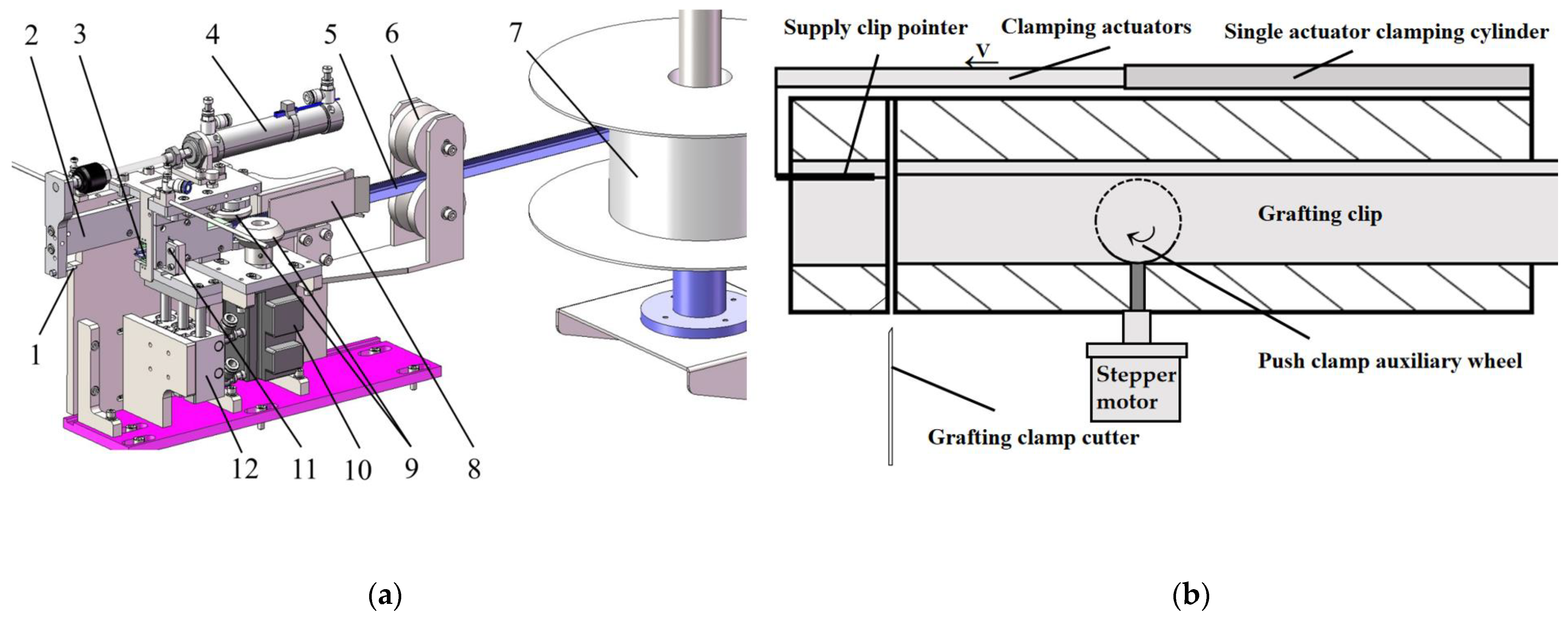
2.4.3. Structural Design of the Push-Up Clamping Mechanism

  • Architectural Design
The push-up clip mechanism is shown in Figure 8a,b. This mechanism is mainly composed of the grafting clip clamping finger, the finger clamping cylinder, the lifting stepper motor, the lifting track, the pushing stepper motor, the pushing track, and the advancing limit sensor. When the supply clip mechanism sends the wrapped clip to the take-clip position, the lift stepper motor and push stepper motor work in sync. The clamping finger is pushed to the take-clip position. At this point, the first limit sensor is triggered, sending a signal to the system. The clamping finger cylinder is turned off, allowing the clamping finger to grip the grafting clip tail. The retractable cylinders of the feeder retract, and the pushing stepper motor continues to move, pushing the grafting clip and clamping finger to the position for attachment. When the second limit sensor is triggered, the system receives the signal, and the finger clamping cylinder opens to fix the grafted seedling in place, completing the grafted seedling clamping process.
2.
Stepping Motor Selection for the Upper Clamping Mechanism
This paper selects the appropriate ball screw and stepping motor through specific theoretical calculations, considering the role of the stepping motor and the stepping clamping module of the clamping system to estimate the quality of the appropriate ball screw and stepping motor [48,49,50,51]. As shown in Figure 8d, the force diagram of the stepper motor is included. This selection process ensures that the motion control requirements of the clamping system are met, guaranteeing that the clamping mechanism can accurately, stably, and reliably pick up and feed the clamps.
The axial load calculation formula is
F = F a + G · ( s i n α + μ · c o s α )
The initial torque is
T = L · F · s i n α
The initial load is
F 0 = F 3
The load torque is
T L = T · P b + μ 0 · F 0 · P b · η 2 π η · 1 i
In the formula, Fa is the applied external force, N; F0 is the initial load, N; G is the total mass of the upper clamping part, kg; α is the inclination angle between the ball screw and the upper clamping mechanism, (°); Pb is the lead of the ball screw, mm; η is the efficiency of the transmission system, %; μ is the coefficient of sliding friction; μ0 is the coefficient of friction of the bolts of the ball screw; and i is the ratio of the transmission.
The propulsion and upper clamping part of the clamping system is mainly made of aluminum alloy and stainless steel using a milling process. It includes components such as a clamping finger cylinder, clamping finger, mounting plate, pushing and lifting track, and other parts. The overall mass of the mechanism is 1.86 kg. The selected shaft diameter is 16 mm, with a lead of 5 mm, while the ball screws have a shaft diameter of 12 mm and a lead of 5 mm. The propulsion and elevation stepping motors are arranged horizontally and vertically, as shown in Figure 8d.
According to the installation direction of the stepping motor of the mechanism, it can be seen that the angle in the horizontal direction is 180°, and the angle in the vertical direction is 90°; based on the type of screw selected and the actual operation of the upper clamping mechanism, the following values can be determined: Fa = 0, μ = 0.05, μ0 = 0.3, η = 0.85, and I = 0.95. Using these data, and substituting them into Equations (10)–(12), the simplified form of Equation (13) yields the load moment equations for both the horizontal and vertical directions.
The horizontal load moment is
T L = G · P b 2 π η · 1 i · 2
The vertical arrangement of the load moment is
T L = G · P b 2 π η · 1 i
Under the condition that the stepping motor is arranged horizontally and vertically, the advancing torque of the clamping mechanism depends on the lead of the ball screw and the total mass of the pushing parts. Substituting the data into Equations (14) and (15), the load torque is calculated as 3.56 N·m in the horizontal direction and 1.83 N·m in the vertical direction. To ensure safe and stable operation, and to prevent undesirable consequences caused by material deficiencies, work deviations, or sudden increases in external forces, a safety factor of 1.3 is chosen for highly reliable materials that are not subject to severe loads and environmental conditions. A higher safety coefficient of 1.5 is chosen for uncertainty in this design. Based on this, the required torques of 5.5 N·m and 2.6 N·m were calculated, leading to the selection of the Doena 60DNA2-0D40KAM stepper motor for the horizontal direction and the Leadshine 57CM31 stepper motor for the vertical direction, as shown in Figure 8c.

3. Results and Discussion

3.1. Results of Grafting Trials

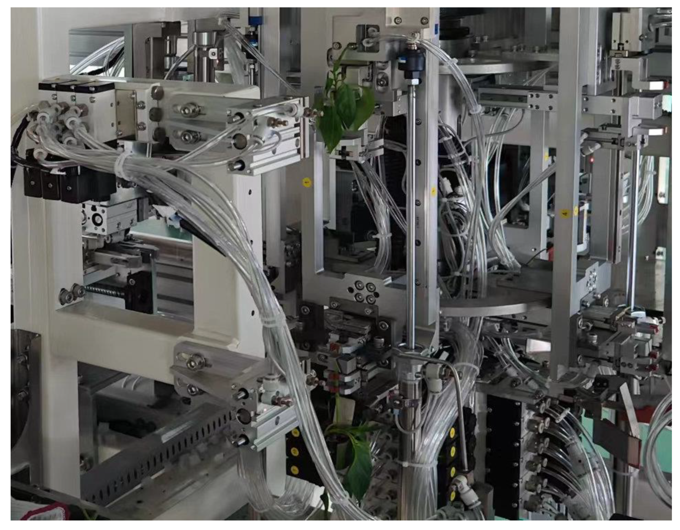
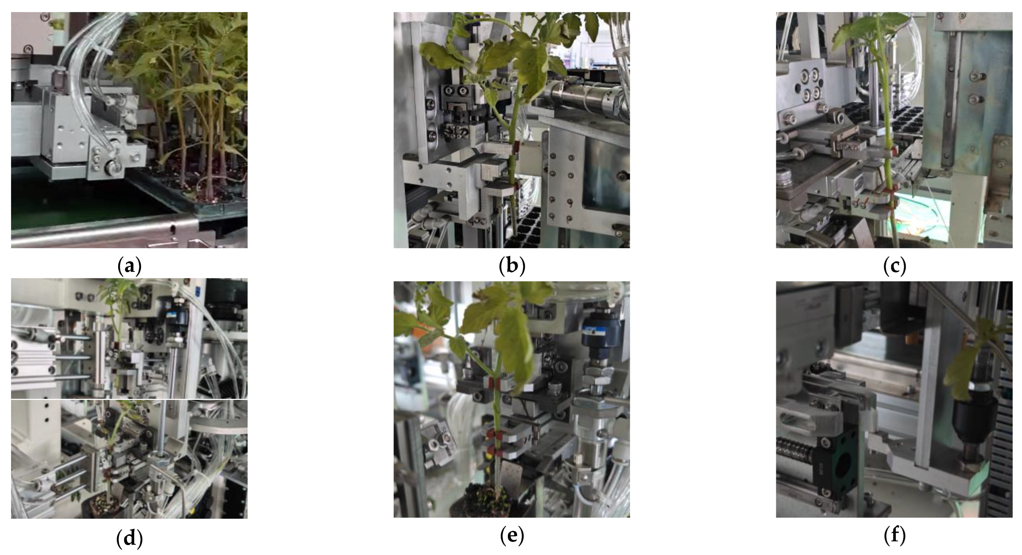
3.1.1. Development of an Automated Grafting Device for Eggplant and Tomato Seedlings

According to the conclusions from previous structural design and mechanism research on the key components of the grafting device, this study successfully completed the fabrication of three essential parts: the automated cutting device, the attaching device, and the clamping device specifically designed for eggplant. This project involved close collaboration with the designers of other components and control systems, resulting in the final prototype production and the assembly of a fully automated and synchronized grafting device, intended for use with both eggplant and tomato fruit. The new device integrates several critical functionalities: automatic seedling handling for scion wood, the efficient transit of scion seedlings, precise clamping mechanisms, the synchronized cutting of scion seedlings, effective graft attachment, a continuous clamp supply system, and a bandaging process for the clamp. Each of these components was rigorously tested to assess their performance within the overall grafting operation, with the goal of determining both the grafting success rate and the production efficiency of the grafting device.
To evaluate the performance of the device, several key metrics were examined, including the alignment of the rootstock and scion cuts, the stability and continuity of clamping, and the rate of clamping damage. These metrics are crucial for assessing the success rate of the key operating mechanisms and verifying the accuracy and functionality of the components designed in the previous stages. The criteria for determining the success rate of the cutting process primarily focus on whether the cutting lengths of the rootstock and scion meet the specified requirements for the optimal cutting angle fit. The success rate for single-plant grafting depends on the precise alignment of the cutting angles and whether the grafting butterfly clamp wraps around the grafted seedling’s incision, ensuring a firm attachment.
The overall productivity of the machine was measured from the moment the first plant was inserted into the hole plate until the last plant was processed. The trial meticulously recorded the number of successful grafts and the time taken to graft a full plate of rootstock and scion seedlings. These data were then used to calculate the productivity metrics of the machine’s operation over a designated unit of time. The experimental assessment was conducted in ten distinct groups, utilizing a total of 72 holes for Tolubam rootstock and 72 holes for Nova 101 tomato scion, both selected during their optimal grafting suitability period. The first five groups focused on testing the cutting effectiveness, measuring the geometric parameters of both the rootstock and scion cuts, while also calculating the surface fitting rate of the cuts. The last five groups concentrated on evaluating grafting success and overall productivity. The prototype used in these tests is illustrated in Figure 9.

3.1.2. Evaluation of Cutting Parameters for Enhanced Grafting Success in Eggplant and Tomato Seedlings

According to the conclusions from previous research on the cutting mechanism and the process requirements for vegetable grafting, the cutting angles of the scion and rootstock cutting blades were adjusted to 30° and 35°, respectively. Measurements were conducted after completing the cutting process, with the tests divided into five groups. The data from each group were averaged, and the results are summarized in Figure 10 and Table 5.
The data presented in Table 5 reveal that the cutting parameter tests resulted in a rootstock shaft diameter of approximately 5.6 mm and a shaft length of around 9.7 mm. In comparison, the scion exhibited a shaft diameter of about 4.8 mm and a shaft length of approximately 7.2 mm, resulting in a stem thickness difference of less than 1.0 mm between the selected rootstock and scion. The average length of the beveled section of the scion, cut at an angle of 30°, was measured at 9.60 mm, while the beveled section length for the rootstock, cut at an angle of 35°, was 9.76 mm. Notably, the fitting rate of the sections reached an impressive range of 97.4% to 98.7%.
In accordance with the grafting process requirements for Solanaceae vegetables, the effective length of the beveled surface must be at least 5 mm, and the surface fitting rate should be more than 90%. These parameters are critical in achieving a high survival rate in grafting operations. The results of the cutting parameter test meet these criteria, thereby validating the feasibility of the cutting mechanism study and the design of the cutting equipment described in the Methods section.

3.1.3. Results of the Whole Machine Grafting Success Rate Test

After conducting tests on the cutting mechanism of the pre-grafting device, the objective was to assess the feasibility of cutting angles for rootstocks and scions. Based on this evaluation, the overall grafting success rate of the equipment was also examined. The tests were organized into five distinct groups, with the results summarized in Table 6. The data in Table 6 showed that, after completing five comprehensive tray grafting tests, the automated synchronous grafting equipment designed in this study was capable of grafting approximately 700 seedlings per hour. The average time for a single grafting operation was 5.13 s. The cycle time for a single-stroke, four-channel grafting process was 14 s, and completing the entire grafting operation for a 72-hole grafting tray took 370 s. The test procedure is shown in Figure 11. These figures highlight a significant increase in efficiency compared to the existing fully automated grafting facilities available on the market.
The cutting mechanism for both the rootstock and scion achieved a cutting success rate over 97%. Furthermore, the affixing success rate reached exceeded 95%, and the overall grafting success rate was greater than 91%. The cutting, clamping, pasting, and upper clamping and wrapping mechanisms designed in this study operated reliably and successfully completed the grafting process. However, a few challenges were encountered during testing. A small number of stalks experienced affixing failures, primarily due to the machine’s operational mode, which processes a full tray of seedlings in a single grafting cycle. This method resulted in variations in seedling growth, including thinner axis diameters or excessive curvature in some seedlings. During the cutting operation, the thrust and retraction of the cutting blade could cause bending in these stalks. In the affixing operation, significant differences in the axis diameters of the rootstock and scion occasionally led to instability in the affixing process. Additionally, during the bandaging operation, the minimal difference in stem thickness between the rootstock and scion occasionally resulted in an uneven clamping force from the butterfly clamp, particularly on the thinner side of the stalks, which could lead to detachment.
Despite these minor setbacks, the overall performance of the grafting facility proved to be of high quality. The average grafting success rate reached an impressive 95.2% after repeated tests, underscoring the machine’s effectiveness in both the affixing and wrapping processes.

3.2. Discussion

(1) This paper designs a clamping and wrapping system that includes a continuous clamping system and a push-up clamping mechanism composed of two parts. Compared with the common existing pulse-vibration-type PVC loading tray, the stability and operational safety of the system have been significantly improved. These improvements are mainly reflected in the following three aspects: 1. The traditional pulse-vibration type generates large vibration to achieve the grafting clip action and uses multiple adjustable clip bars to direct the grafting clip, which can easily lead to clip supply clogging. In contrast, the continuous clamping system designed in this study reduces the volume by 50%. Additionally, the system uses a whole-plate PE butterfly clip that consistently maintains a horizontal direction, avoiding clip supply clogging. 2. Traditional pulse-vibration systems are expensive, while the clamping device in this study requires only one stepper motor and one cutting cylinder, reducing the cost by 40%. 3. Traditional pulse-vibration systems are limited to producing grafting clamps made of PVC, a hard plastic with an inclined clamping surface. In contrast, the design in this study uses a PE soft rubber butterfly-shaped grafting clip, where the clamping surface and the plant stem can be tightly fitted together. This design significantly reduces the damage to the seedlings, during both the wrapping process and clamping, compared to the traditional system.
(2) Compared with the common grafting system, the integrated mechanism of clamping and attaching designed in this study significantly improved the grafting efficiency and attaching accuracy. In the traditional grafting device, the seedling must be transferred after cutting before the splicing operation can be performed. However, the clamping and wrapping integrated mechanism designed in this study eliminates this step. After cutting, telescopic cylinders directly transport the upper part of the scion seedling to the seedling docking. This design fundamentally avoids the transfer vibration and positional inaccuracies that often result from attachment precision. As a result, the integrated mechanism outperforms traditional attachment mechanisms in terms of both efficiency and accuracy.
(3) The article includes a cutting angle test for grafted seedlings and a safety verification of a PE polyethylene rubber butterfly clip. The morphological data and mechanical characteristic parameters of common Solanaceae grafted seedlings were obtained, enabling consistency in the cutting surface of rootstock seedlings and scion seedlings. This consistency is a critical factor in enhancing the cutting precision and grafting quality of rootstock seedlings. If applied to other types of grafting devices, it could facilitate automated adjustments to cutting mechanism parameters, providing researchers with valuable guidance for designing clamping mechanisms and selecting materials. The findings from this study serve as an important reference for optimizing and intelligently upgrading the clamping and cutting mechanism of grafting devices, making a significant step in the development of advanced grafting devices.
(4) The fully automatic grafting facility designed by this institute can perform grafting operations seamlessly, from processing seedlings in a whole hole to delivering finished seedlings in a yard tray. However, the machine also has some limitations. Most of the key components of the machine are of non-standard designs, resulting in high production costs. The complex structure of the machine leads to extended commissioning times and high maintenance costs during later stages. Additionally, the cutting mechanism lacks a visual recognition function, preventing it from recognizing the crop growing point and thus limiting its applicability to Solanaceae plants. Compared to a semi-automatic grafting facility, the working mode of this machine is more complicated, requiring the recalibration of several parameters and adjustments to certain components when switching the type of plant or the method of grafting. While semi-automatic grafting equipment is relatively simple to adjust and adapts more quickly to different grafting tasks, it achieves lower productivity than the fully automatic grafting machine.

4. Conclusions

(1) To address issues such as seedling stem damage and affixing deviation in the grafting process, which result in low survival rate of grafted finished seedlings, this paper proposes a new type of single-stroke, four-channel eggplant grafting machine. The machine is designed based on the affixing method of the comprehensive machine design scheme. By incorporating a cutting angle test, PE grafting clip safety verification, and the design of the cutting mechanism, affixing mechanism, and automatic clip supply system, the machine achieves several key functions. These include the synchronous cutting of scion seedlings, the precise attachment of scion seedlings, a continuous supply of grafting clips, the wrapping of attached seedling in clips, and the placement of finished seedlings in yard trays.
(2) In order to determine the optimal cutting angle, tests were carried out on rootstock and scion seedlings to analyze the structural and morphological characteristics. These tests identified the final cutting angle and cutting surface parameters for rootstock seedlings. The optimal combination of the affixed seedlings was achieved by measuring and calculating their lengths. The optimal cutting angles of the rootstock and scion seedlings were determined, and then the grafting test was carried out. The research results provide valuable insights for the development, transformation, and upgrading of the cutting mechanism in eggplant and fruit grafting machines.
(3) Using 72 holes of Tolu Bam rootstock and 72 holes of Nova 101 tomato scion during the optimal grafting period, a comprehensive grafting test and cutting quality evaluation were conducted with the automatic synchronized grafting machine for Lycopersicon. The test results showed that the cutting success rate exceeded 97%, while the success rate of grafting seedling attachment was more than 95.6%. Additionally, the success rate of grafting seedlings on the clamp was over 96.4%, with an overall grafting success rate of at least 91.6%. The machine exhibited a productivity of 700 plants per hour, with no observed loss during seedling clamping.
(4) The machine enables fully automated grafting operation for eggplant and fruit vegetables, providing a mechanized grafting workflow for the nursery industry and significantly reducing the labor demands. However, certain limitations exist due to cost control and design considerations. The machine predominantly relies on a cylinder for operation, requiring connection to an external air compressor. Future research could explore replacing the cylinders with servo motors to achieve a more integrated system. During the attachment process, discrepancies in the size of the rootstock and scion could result in under-attachment. Additionally, in the finished seedling trays, overly large cotyledons could affect the clamping jaw placement. Therefore, it is necessary to control the seedlings’ maturity according to the nursery manual. Moreover, during the cutting operation, discarded scion stems and leaves may fall onto the rootstock clamping jaws, potentially causing attachment failures. To mitigate this issue, a debris removal mechanism will be designed to address this problem in future studies.

Author Contributions

Conceptualization, Z.L. and C.Z.; methodology, C.Z.; software, Z.L. and F.W.; validation, Z.L. and J.L.; formal analysis, Z.L. and L.J.; investigation, Z.L.; resources, Z.L. and C.Z.; data curation, Z.L. and W.Z.; writing—original draft preparation, Z.L.; writing—review and editing, Z.L., W.Z., C.Z. and G.W.; project administration, C.Z. and G.W.; funding acquisition, C.Z. and G.W. All authors have read and agreed to the published version of the manuscript.

Funding

This study was supported by the Major Science and Technology Special Project of the Autonomous Region, under Project leader Guoqiang Wang and grant number 2022A02005. It was also supported by the Central Guided Local Project, “Xinjiang Facility Green Fruit and Vegetable Production and Processing Engineering and Intelligent Equipment Technology Research and Base Construction”, under Project leader Caihong Zhang, 2023 and grant number ZYYD2023B01, and by the Autonomous Region Tianshan Leading Talent Program, “Design and Construction of Assembled Deep-Winter Production Daylight Greenhouse in Xinjiang and Supporting Key Technology Research and Demonstration”, under Project leader Guoqiang Wang and grant number 2022TSYCLJ0038.

Data Availability Statement

The original contributions presented in this study are included in the article. Further inquiries can be directed to the corresponding authors.

Conflicts of Interest

The authors declare no conflicts of interest.

Appendix A

Figure A1. (a) Schematic before and after clamping: 1. elastic spacer; 2. grafted seedling. (b) Elastomeric shims made of different materials.
Processes 13 00131 g0a1

References

  1. Huang, Y.; Kong, Q.; Chen, F.; Bie, Z. The history, current status and future prospects of vegetable grafting in China. Int. Symp. Veg. Grafting 2014, 1086, 31–39. [Google Scholar] [CrossRef]
  2. Qu, D. In History and status of the vegetable industry in China. In XXVI International Horticultural Congress: Asian Plants with Unique Horticultural Potential: Genetic Resources. Cultural 2002, 620, 43–51. [Google Scholar]
  3. Hu, W.; Zhang, Y.; Huang, B.; Teng, Y. Soil environmental quality in greenhouse vegetable production systems in eastern China: Current status and management strategies. Chemosphere 2017, 170, 183–195. [Google Scholar] [CrossRef]
  4. Gaion, L.A.; Braz, L.T.; Carvalho, R.F. Grafting in Vegetable Crops: A Great Technique for Agriculture. Int. J. Veg. Sci. 2018, 24, 102–185. [Google Scholar] [CrossRef]
  5. Frank, M.H.; Chitwood, D.H. Plant chimeras: The good, the bad, and the ‘Bizzaria’. Dev. Biol. 2016, 419, 41–53. [Google Scholar] [CrossRef] [PubMed]
  6. Khah, E.; Kakava, E.; Mavromatis, A.; Chachalis, D.; Goulas, C. Effect of grafting on growth and yield of tomato (Lycopersicon esculentum Mill.) in greenhouse and open-field. J. Appl. Hortic. 2006, 8, 3–7. [Google Scholar] [CrossRef]
  7. Khah, E. Effect of grafting on growth, performance and yield of aubergine (Solanum melongena L.) in the field and greenhouse. J. Food Agric. Environ. 2005, 3, 92–94. [Google Scholar]
  8. Frey, C.J.; Zhao, X.; Brecht, J.K.; Huff, D.M.; Black, Z.E. High Tunnel and Grafting Effects on Organic Tomato Plant Growth and Yield in the Subtropics. HortTechnology 2020, 30, 492–503. [Google Scholar] [CrossRef]
  9. Louws, F.J.; Rivard, C.L.; Kubota, C. Grafting fruiting vegetables to manage soilborne pathogens, foliar pathogens, arthropods and weeds. Sci. Hortic. 2010, 127, 127–146. [Google Scholar] [CrossRef]
  10. Bogoescu, M.; Doltu, M.; Sora, D. Prevention and control of soilborne diseases and nematodes in eggplants crop by grafting plants combined with soil fumigation. In Proceedings of the VIII International Symposium on Chemical and Non-Chemical Soil and Substrate Disinfestation 1044, Turin, Italy, 13–17 July 2014; pp. 331–336. [Google Scholar]
  11. Baiyang, L. Vegetable grafting machine research status and development trend. Agric. Mach. Using Maint. 2015, 4, 2. [Google Scholar]
  12. Devi, P.; Lukas, S.; Miles, C. Advances in Watermelon Grafting to Increase Efficiency and Automation. Horticulturae 2020, 6, 88. [Google Scholar] [CrossRef]
  13. Song, G.; Linbin, J. Development of domestic and foreign vegetable grafting robot. J. Northeast Agric. Univ. 2007, 6, 5. [Google Scholar]
  14. Lee, J.M.; Kubota, C.; Tsao, S.J.; Bie, Z.; Echevarria, P.H.; Morra, L.; Oda, M. Current status of vegetable grafting: Diffusion, grafting techniques, automation. Sci. Hortic. 2010, 127, 93–105. [Google Scholar] [CrossRef]
  15. Kubota, C.; McClure, M.A.; Kokalis-Burelle, N.; Bausher, M.G.; Rosskopf, E.N. Vegetable grafting: History, use, and current technology status in North America. HortScience 2008, 43, 1664–1669. [Google Scholar] [CrossRef]
  16. Hai, Y. Japanese sop-jag800-u automatic grafting machine. New Rural Technol. 2017, 10, 40. [Google Scholar]
  17. An, S.; Bae, J.H.; Kim, H.C.; Kwack, Y. Production of grafted vegetable seedlings in the republic of Korea: Achievements, challenges and perspectives. J. Hortic. Sci. Technol. 2021, 39, 547–559. [Google Scholar] [CrossRef]
  18. Chang, Y.-C.; Chen, S.; Chiu, Y.-C.; Lin, L.-H.; Chang, Y.-S. Environment, Biotechnology, Growth and union acclimation process of sweet pepper grafted by a tubing-grafting robotic system. Environ. Biotechnol. 2012, 53, 93–101. [Google Scholar]
  19. Yetısir, H.; Sari, N.; Yucel, S. Rootstock resistance to Fusarium wilt and effect on watermelon fruit yield and quality. Phytoparasitica 2003, 31, 163–169. [Google Scholar] [CrossRef]
  20. Yan, G.; Feng, M.; Lin, W.; Huang, Y.; Tong, R.; Cheng, Y. Review and Prospect for Vegetable Grafting Robot and Relevant Key Technologies. Agriculture 2022, 12, 1578. [Google Scholar] [CrossRef]
  21. Jiang, K.; Zhang, Q.; Xiu, W.; Qingchun, F.; Rui, G. Design for Automatic Sequencing and Supplying Device for Grafting Clips. Trans. Chin. Soc. Agric. Mach. 2012, 43, 256–261. [Google Scholar]
  22. Jun, L.; Tiezhong, Z.; Jia, C.; Libo, Z.; Wenbo, Z.; Quan, Y. Design and Experiment of Grafting-clip Transporting Mechanism of Full Automatic grafting machine for Whole-row Vegetable Seedlings. Trans. Chin. Soc. Agric. Mach. 2017, 48, 14–20. [Google Scholar]
  23. Jiasheng, W.; Mei, Z.; Chunfeng, G.; Shuqi, S.; Dongwei, W. Design and Test of Key Components of Vegetable Grafting Robot for Plug Seedlings. Trans. Chin. Soc. Agric. Mach. 2023, 54, 38–45. [Google Scholar]
  24. Jia, C. Research on Fully Automatic Grafting System for Entire Tray Solanaceae Seedlings. Ph.D. Thesis, China Agricultural University, Beijing, China, 2017. [Google Scholar]
  25. Xu, P.; Zhang, T.; Chen, L.; Huang, W.; Jiang, K. Study on the Method of Matched Splice Grafting for Melon Seedlings Based on Visual Image. Agriculture 2022, 12, 929. [Google Scholar] [CrossRef]
  26. Jiang, K.; Guo, W.; Chen, L.; Huang, W.; Ge, Y.; Wei, X. Design and Experiment of Automatic Clip-Feeding Mechanism for Vegetable-Grafting Robot. Agriculture 2022, 12, 346. [Google Scholar] [CrossRef]
  27. Wang, C.; Song, C.; Song, J. Optimization and test of working parameters of cutting device of vegetable grafting machine. J. Phys. 2023, 2528, 012003. [Google Scholar] [CrossRef]
  28. Morini, S. The use of the grafted cutting and of a grafting machine in fruit production. Inf. Agrar. 1980, 36, 12583–12586. [Google Scholar]
  29. Zhao, X.; Wang, Z.; Liu, S.; Wang, R.; Tian, S. Grading system of tomato grafting machine based on machine vision. In Proceedings of the 2015 8th International Congress on Image and Signal Processing, Jeju Island, Republic of Korea, 25–28 November 2015; pp. 604–609. [Google Scholar]
  30. Fu, X.; Shi, J.; Huang, Y.; Zhu, E.; Bie, Z.; Lin, W. Design and Experiment of Full-Tray Grafting Device for Grafted Melon Seedling Production. Agriculture 2022, 12, 861. [Google Scholar] [CrossRef]
  31. Comba, L.; Gay, P.; Aimonino, D.R. Robot ensembles for grafting herbaceous crops. Biosyst. Eng. 2016, 146, 227–239. [Google Scholar] [CrossRef]
  32. Chen, S.; Liang, H.; Zhang, Q.; Feng, Q.; Li, T.; Chen, L.; Jiang, K. Melon Robotic Grafting: A Study on the Precision Cutting Mechanism and Experimental Validation. Agriculture 2023, 13, 2139. [Google Scholar] [CrossRef]
  33. Pardo-Alonso, J.-L.; Carreño-Ortega, Á.; Martínez-Gaitán, C.-C.; Callejón-Ferre, Á.-J. Combined Influence of Cutting Angle and Diameter Differences between Seedlings on the Grafting Success of Tomato Using the Splicing Technique. Agronomy 2019, 9, 5. [Google Scholar] [CrossRef]
  34. Zhiyu, M.; Hongyu, W.; Yinghui, M.; Song, G. Determination of insertion angle of hole-insertion grafting method by grafting machine. Trans. Chin. Soc. Agric. Eng. 2014, 30, 43–49. [Google Scholar]
  35. Wu, K.; Lou, J.; Li, C.; Li, J. Experimental Evaluation of Rootstock Clamping Device for Inclined Inserted Grafting of Melons. Agriculture 2021, 11, 736. [Google Scholar] [CrossRef]
  36. Yinghui, M.; Song, G.; Zhiyu, M. Experimental analysis on biomechanical properties of cucurbits grafted seedlings. Trans. Chin. Soc. Agric. Eng. 2012, 28, 6. [Google Scholar]
  37. Yi, Z.; Jinjiang, Y. Innovative development of modern facility agriculture: Theoretical logic, realistic situation and reform path. Dongyue Trib. 2024, 45, 68–77. [Google Scholar]
  38. Jiaxiu, C.; Lin, C. Effect of different commodity substrates on pepper seedling cultivation. J. Chang. Veg. 2024, 24, 10–13. [Google Scholar]
  39. Hassell, R.L.; Memmott, F.; Liere, D.G. Grafting methods for watermelon production. HortScience 2008, 43, 1677–1679. [Google Scholar] [CrossRef]
  40. Mohamed, F.; Abd El-Hamed, K.; Elwan, M.; Hussien, M. Evaluation of different grafting methods and rootstocks in watermelon grown in Egypt. Sci. Hortic. 2014, 168, 145–150. [Google Scholar] [CrossRef]
  41. Cveticanin, L.; Maretic, R. Dynamic analysis of a cutting mechanism. Mech. Mach. Theory 2000, 35, 1391–1411. [Google Scholar] [CrossRef]
  42. Fariborz, H.; Tie, L.; Kevin, F.; Ali, S. Physiological, biochemical, and molecular aspects of grafting in fruit trees. Hortic. Res. 2022, 9, uhac032. [Google Scholar]
  43. Islam, M.N.; Iqbal, M.Z.; Ali, M.; Chowdhury, M.; Kabir, M.S.N.; Park, T.; Kim, Y.-J.; Chung, S.-O. Kinematic Analysis of a Clamp-Type Picking Device for an Automatic Pepper Transplanter. Agriculture 2020, 10, 627. [Google Scholar] [CrossRef]
  44. Yue, R.; Hu, J.; Liu, Y.; Yao, M.; Zhang, T.; Shi, J. Design and Working Parameter Optimization of Pneumatic Reciprocating Seedling-Picking Device of Automatic Transplanter. Agriculture 2022, 12, 1989. [Google Scholar] [CrossRef]
  45. Devouge, S.; Salvagnini, C.; Marchand-Brynaert, J. A practical molecular clip for immobilization of receptors and biomolecules on devices’ surface: Synthesis, grafting protocol and analytical assay. Bioorg. Med. Chem. Lett. 2005, 15, 3252–3256. [Google Scholar] [CrossRef] [PubMed]
  46. Huerta, E.; Corona, J.; Oliva, A.; Avilés, F.; González-Hernández, J. Universal testing machine for mechanical properties of thin materials. Rev. Mex. Física 2010, 56, 317–322. [Google Scholar]
  47. Kai, L.; Qi, C.; Yuanqiang, L.; Yanqiu, L.; Yan, Y. Research Development of Solanaceae Vegetables Automatic grafting machines. J. Agric. Mech. Res. 2011, 33, 230–233. [Google Scholar]
  48. Caracciolo, R.; Richiedei, D. Optimal design of ball-screw driven servomechanisms through an integrated mechatronic approach. Mechatronics 2014, 24, 819–832. [Google Scholar] [CrossRef]
  49. Chirikjian, G.S.; Stein, D. Kinematic design and commutation of a spherical stepper motor. IEEE/ASME Trans. Mechatron. 1999, 4, 342–353. [Google Scholar] [CrossRef]
  50. Johnson, J.G.; Engineer, P.; Wood Dale, I. Selecting and Sizing Ball Screw Drives. Power Transm. Eng. 2012, 6, 36–39. [Google Scholar]
  51. Yılmazlar, E.; Erdemir, V.; Kuşçu, H.; Güllü, A. Design of Stepper Motor Control Interface with Embedded Systems. Int. J. Eng. Res. Dev. 2018, 14, 17–22. [Google Scholar]
Figure 1. Three-dimensional design scheme of automated grafting machine for eggplant and fruits: 1. rootstock picking mechanism; 2. rootstock conveying mechanism; 3. clamping seedling loading mechanism; 4. synchronized cutting mechanism; 5. attaching and wrapping mechanism; 6. scion conveying mechanism; 7. finished seedling palletizing mechanism; 8. scion picking mechanism; 9. rootstock transferring mechanism; and 10. scion transferring mechanism.
Processes 13 00131 g001
Figure 2. (a) Schematic diagram of seedling cutting angle. (b) Position of the cutter in relation to the stalk: 1. upper clamping jaw; 2. cutting blade; 3. lower clamping jaw; l. cutting height; d. seedling diameter; α. cutting angle; L. length of oblique cuts; and H. seedling height.
Processes 13 00131 g002
Figure 3. (a) Synchronized cutting device for rootstocks and scions: 1. pusher cylinder; 2. mounting frame; 3. telescopic pusher; 4. fixed tool holder; 5. cutting blade; and 6. knife stopper. (b) Rootstock and scion cutting process.
Processes 13 00131 g003
Figure 4. (a) Scion and rootstock clamping mechanism: 1. Scion upper jaw; 2. Scion seedling to be affixed; 3. Scion letting block; 4. Scion lower jaw; 5. Upper jaw clamping cylinder; 6. Scion clamping distance-adjusting bolt; 7. Scion clamping lift-adjusting bolt; 8. Scion lower jaw telescopic cylinder; 9. Scion lower jaw clamping cylinder; 10. Anvil upper jaw telescopic cylinder; 11. Anvil upper jaw; 12. Anvil let-off block; 13. Anvil lower jaw; 14. Anvil seedling to be affixed; 15. Anvil clamping distance-adjusting bolt; and 16. Anvil lower jaw clamping cylinder. (b) Effective connection of scion and rootstock: 1. Jointed surface and 2. Anvil lifting and laminating cylinders.
Processes 13 00131 g004
Figure 5. (a). Common grafting clips for grafting operations: 1. steel ring spring grafting clamps; 2. hand grafting clamps; 3. grafting sleeves; and 4. PE polyethylene rubber butterfly clamps. (b). Schematic diagram of grafting clamp structure modeling.
Processes 13 00131 g005
Figure 6. (a). Force analysis of the graft clamp in compression. (b). Graft clamp compression test: 1. compression indenter; 2. support; 3. PE grafting clamp; 4. clamping shank parallel state.
Processes 13 00131 g006
Figure 7. (a) Structure of continuous clamping mechanism: 1. clamping pointer; 2. cylinder guide; 3. cut grafting clamps; 4. Single-pusher clamping cylinders; 5. grafting clamps to be cut; 6. stroke clamping pressure wheel; 7. whole plate loader; 8. clamping guide rail; 9. clamping auxiliary wheel; 10. clamping stepping motor; 11. mounting knife holder and cutter; and 12. clamping cylinders. (b) Cutaway schematic of the continuous clamping mechanism.
Processes 13 00131 g007
Figure 8. (a) Structural diagram of the push-up clamping mechanism: 1. push stepper motor; 2. mounting frame; 3. elevation guide; 4. threader; 5. elevation stepper motor; 6. grafted-clamped fingers; 7. grafting finger clamping cylinder; 8. clamping finger mounting bracket; 9. pushing track; 10. Fixed baffle. (b) Clamping and bandaging procedure. (c) Push and lift motor layout and (d) schematic diagram of the state of stepping motor subjected to external force.
Processes 13 00131 g008
Figure 9. Grafting machine assembly prototype.
Processes 13 00131 g009
Figure 10. Schematic diagram of the cutting test.
Processes 13 00131 g010
Figure 11. The process of automated grafting machine for eggplant and fruits: (a) rootstock and scion in position; (b) scion clamping; (c) rootstock clamping; (d) synchronized cutting of rootstock and scion; (e) attachment of rootstock and scion; (f) continuous clamping mechanism; (g) push up on the clip wrap (h) grafted seedling placed in a tray; (i) finished grafted seedlings.
Processes 13 00131 g011aProcesses 13 00131 g011b
Table 1. Rootstock and scion cutting length and cutting angle matching data.
Cutting Angle
α (°)
Rootstock: Tolu BamScion: Tomato New Star 101
Mean Stem Diameter
D (mm)
Length of Beveled Section
L1 (mm)
Mean Stem Diameter
d (mm)
Length of Beveled Section
L2 (mm)
205.64 ± 0.16
(CV 2.83%)
16.49 ± 0.214.83 ± 0.12
(CV 2.48%)
14.12 ± 0.18
2513.35 ± 0.1411.43 ± 0.14
3011.28 ± 0.189.66 ± 0.27
359.83 ± 0.258.42 ± 0.12
408.77 ± 0.247.51 ± 0.26
457.98 ± 0.176.83 ± 0.13
Table 2. Clamping characteristics of rigid iron bars with different elastic shims.
Movement of the Indenter
(mm)
Pressure Values on Rigid Iron Bars at Different Levels of Compression (N)
Highly Elastic Rubber38-Degree EVA FoamHigh Density Xps Extruded PlasticPolyurethane Shock Pads
23.78 ± 0.841.45 ± 0.722.03 ± 0.642.73 ± 0.48
47.18 ± 0.633.26 ± 0.774.88 ± 0.574.97 ± 0.51
58.42 ± 0.814.87 ± 0.586.25 ± 0.737.38 ± 0.45
610.07 ± 0.556.33 ± 0.527.31 ± 0.438.66 ± 0.68
Note: 20 pieces of elastic shims were prepared as test samples for each group; ± mean standard deviation of values.
Table 3. Parameter list of PE polyethylene rubber grafting clip.
Clamp StructureClamp Body MaterialInitial Length Initial Clamping DiameterClamp Grip Distance Clamp Body Width Clamp Body Height Clamp Body Mass
L0 (mm)L1 (mm)L2 (mm)b (mm)h (mm)m (g)
One-piece MoldingPE Polyethylene2.53.710.514.510.00.52
Table 4. Test results of grafting clamp clamping force test on Solanaceae plants.
Types of Grafted SeedlingsStem Thickness
(mm)
Seedling Elasticity Limit Value (N)Clamp Opening
(mm)
Clamp Shank Compression (mm)Clamping Shank Average Pressure (N)Maximum Jaw Clamping Force (N)
Carter 1884.87 ± 0.398.293.92 ± 0.221.69 ± 0.293.563.28
Jiaozhen 1085.16 ± 0.428.974.39 ± 0.352.87 ± 0.345.253.55
China Pepper No.55.66 ± 0.4010.835.28 ± 0.274.10 ± 0.428.333.88
Red Choice Pepper King5.53 ± 0.619.744.86 ± 0.423.83 ± 0.377.203.62
Tolu Bam5.62 ± 0.4410.355.28 ± 0.304.10 ± 0.288.333.87
Nova 1014.80 ± 0.328.123.95 ± 0.231.61 ± 0.253.513.25
Note: 20 seedlings were prepared for each group as sample seedlings; ± mean standard deviation of values.
Table 5. Seedling cutting geometry parameter validation test.
Test NumberScion: Tomato New Star 101Rootstock: Tolu BamCut Surface Fit Rate/%
Shaft Diameter (mm)Shaft Length (mm)Length of Beveled Section (mm)Shaft Diameter (mm)Shaft Length (mm)Length of Beveled Section (mm)
14.887.259.785.649.389.8197.4%
24.767.109.505.439.449.4398.2%
34.837.229.665.619.179.7898.7%
44.797.289.525.759.2510.0295.6%
54.777.359.585.589.309.7797.8%
Table 6. Grafting machine: each key mechanism’s success rate test results. Scion: S, rootstock: R.
Test NumberTotal Number of PlantsNumber of Successful Seeding (Grains)Number of Successful Cuts (Grains)Number of Successful Attachments (Grains)Success Rate of Bonding (%)Upper Clip Success Rate (%)Grafting Success Rate (%)Production Efficiency (Grains/h)
SRSR
1144727272727097.210097.2703
2144716970696695.698.491.6677
3144707270726897.198.594.4684
4144727272727097.210097.2727
5144727171716997.110095.8690
Disclaimer/Publisher’s Note: The statements, opinions and data contained in all publications are solely those of the individual author(s) and contributor(s) and not of MDPI and/or the editor(s). MDPI and/or the editor(s) disclaim responsibility for any injury to people or property resulting from any ideas, methods, instructions or products referred to in the content.

