Article

Studying the Characteristics of Tank Oil Sludge

by
Sandugash Tanirbergenova
1,2,
Aisulu Tagayeva
1,
Cesare Oliviero Rossi
3,
Michele Porto
4,
Paolino Caputo
3,
Ernar Kanzharkan
2,
Dildara Tugelbayeva
2,*,
Nurzhamal Zhylybayeva
2,
Kairat Tazhu
2 and
Yerbol Tileuberdi
2
1
Department of Chemistry, Chemical Technology and Ecology, Almaty Technological University, 100, Tole Bi Str., Almaty 050012, Kazakhstan
2
Institute of Combustion Problems, 172, Bogenbay Batyr Str., Almaty 050012, Kazakhstan
3
Department of Chemistry and Chemical Technologies, University of Calabria, Via P. Bucci 45A, 87036 Rende, Italy
4
Department of Civil, Chemical, Environmental and Materials Engineering, University of Bologna, Viale del Risorgimento 2, 40136 Bologna, Italy
*
Author to whom correspondence should be addressed.
Processes 2024, 12(9), 2007; https://doi.org/10.3390/pr12092007
Submission received: 7 August 2024 / Revised: 9 September 2024 / Accepted: 11 September 2024 / Published: 18 September 2024
(This article belongs to the Section Environmental and Green Processes)

Abstract

:
Oil sludge is one of the main pollutants generated by the oil industry. Due to serious pollution and increasing oil production, problems arise every year in the effective treatment of oil sludge. The current study examines the composition and physicochemical characteristics of oil sludge, as well as traditional and new methods for processing oil sludge. With the tightening of environmental protection requirements, oil sludge quality reduction, recycling, and harmless treatment technologies will become necessary in the future. The primary task was to determine the composition of tank oil sludge, separate it from mechanical impurities, and study the influence of ultrasonic treatment and subsequent atmospheric distillation on the extract. The separation of the concentrate and the composition of the tank oil sludge, using an extracted mixture of hexane and benzene, are considered. The use of modern SEM methods, elemental analysis, NMR analysis, IR, ultrasound, and GC–mass spectrometry made it possible to characterize the organic part of reservoir oil sludge and its distillation products. First, 300 g of tank oil sludge was preheated and mixed with 300 mL of solvent (hexane:benzene = 1:1). After mixing with the solvent, the result mixture was filtered. Then, it was placed in an ultrasonic bath and exposed to ultrasound at a frequency of 100 kHz for 30 min. After processing, it was extracted in a Soxhlet apparatus at a temperature of 65 °C to isolate the extract. The resulting extract was analyzed on a gas chromatograph with mass detection. The composition of the extract was as follows (in %): hexane—83.99; total hydrocarbon isomers—7.12; n-hydrocarbons—2.52; benzene—6.37%. At a temperature of 85 °C, the benzene yield was 65.85%. It has been established that the fractions obtained through the distillation of oil sludge at temperatures of 65–85 °C have improved dissolving capacity. It has also been shown that the use of these fractions promotes an increase in the content of hydrocarbon isomers by 12–13% in the extract composition.

1. Introduction

Oil refining, transportation, and storage are primary sources of pollution, and oil sludge is formed during these processes. Oil sludge processing creates additional oil resources and is a necessary way to protect the environment. Under the conditions of continuous exploitation of oil resources and the accompanying environmental pollution, the necessary task of environmental protection is becoming increasingly urgent [1,2,3,4]. Thus, the treatment and reuse of oil sludge in the oil industry has become relevant in recent years. This article examines the characteristics and environmental impacts of oil sludge, as well as the traditional and newly developed oil sludge treatment technologies.
Oil sludge is a dispersion system consisting of water, hydrocarbons, mechanical impurities, and metals [5]. Oil sludge contains oil, asphaltenes, mechanical impurities, and salts of heavy metals. The mass ratio of the components in oil sludge is as follows: hydrocarbons, 35–58% (as a percentage by weight); water, 25–31%; mechanical impurities, 25–25%; metals, 3–15% [6]. The composition of oil sludge is very complex. The hydrocarbon part of oil sludge contains alkanes, aromatic compounds, asphaltenes, anthracenes, pyrene, and other toxic and harmful substances [7].
Oil sludge is toxic waste. The volatilization of oil components in oil sludge increases the concentration of hydrocarbons in the air of adjacent areas and pollutes surface and ground water. Oil sludge contains a large number of toxic and harmful organic compounds such as hydrocarbons, phenols, anthracene, and benzene compounds. Some substances have carcinogenic, teratogenic, and mutagenic effects on the environment [5]. The traditional technologies for cleaning oil sludge include solvent extraction technology, chemical cleaning technology, and pyrolysis technology.
Classic methods for processing heavy oil waste are thermal cracking, catalytic cracking [8], and vibration cracking, which create new marketable products, namely motor fuels. A cheap economical method for utilizing oil waste is proposed, which involves initiating thermal processes. By combining these processes, the yield of light fractions is increased.
The thermal process of oil sludge conversion is more convenient than thermal catalytic conversion. Due to the low quality of the raw materials, large capital investments and operating costs are required. A more rational approach to thermal processes makes it possible to use them effectively, allowing for the introduction of new trends in oil sludge processing.
Through reaction analysis, it was shown that a more effective destructive effect on high-molecular hydrocarbons is achieved via an increase in temperature, i.e., a thermodestructive method. With the addition of external energy, hydrocarbon molecules become mobile and reactive. Developing and disposing of oil waste [9] at high temperatures is one of the ways to obtain light fractions. The future integration and combination of various methods can fully ensure the disposal of oil sludge with a yield of 100%. The use of various disposal methods helps improve the environment with less harm to the ecology of a given region.
To remove some hydrocarbons, the Fenton method is used, which reduces the time required for state regulation and energy costs. However, the oil sludge from the formation contains a large amount of polycyclic aromatic hydrocarbons. In this regard, for the destruction of these hydrocarbons, large amounts of hydrogen peroxide and Fe3+ ions are used in the method. Research shows that the resulting hydroxyl radicals are capable of decomposing organic pollutants such as petroleum hydrocarbons. When processing toxic methanol-containing oil sludge, mixing with demulsifiers in a separate container is required. High interphase activity associated with solid particles, asphaltenes, and naphthenic acids contributes to the formation of a thick, rigid, and stable emulsion layer on the surface of the oil sludge. This process provides physical separation of oil sludge into liquid and solid phases, with subsequent separation of the liquid into oil and water fractions [10,11,12,13].
Various researchers have shown that ultrasonic treatment during the distillation of oil sludge increases the yield of light products due to the breakdown of heavy polycyclic aromatic hydrocarbons [14].
Many researchers in this field consider thermal cracking to be a free radical process, where the production and conversion of oil sludge components are sequential and sequential-parallel reactions.
The extraction of oil sludge is based on the principle of “miscibility”. Organic solvents with properties similar to crude oil are selected to extract petroleum substances from oil sludge. Oil sludge extraction is a typical liquid–solid extraction, which is the process of selecting a suitable extraction solution, mixing it with waste, and then distilling the solvent–oil mixture and separating the oil from the solvent [15]. The solvent is reused after condensation. Common extractants include trichloromethane, propane-triethylamine, and reforming oil. However, the use of chlorine-containing extractants pollutes the resulting secondary hydrocarbons.
Solvent extraction is an effective recyclable treatment method that effectively separates oily sludge into recyclable hydrocarbons, fine solids, and semi-solids [16] and is particularly good for treating large quantities of oil sludge.
Presently, one of the main obstacles to the large-scale application of oil sludge treatment methods is the high consumption of organic extractants; the large amount of organic solvents used can easily cause secondary pollution. The supercritical liquid extraction method makes it possible to effectively [17] reduce the dosage of extractants and shorten the extraction time. However, it is not suitable for large-scale application due to the harsh operating conditions. Thus, searching for highly effective, accessible, and inexpensive extractants or developing new alternative methods for processing oil sludge is relevant.
The purpose of this work is to study the physical and chemical characteristics of tank oil sludge and determine the optimal method for processing it.
The novelty of this work lies in the increased yield of light products of oil sludge processing by 18% using ultrasonic treatment and extraction methods, which ensure the maximum splitting of heavy hydrocarbons into light motor fuels.
This study presents the results of oil extraction from oil sludge in a benzene–hexane mixture at a ratio of 1:1 and a study of the effect of ultrasonic treatment with a frequency of 100 kHz. The ultrasound process aimed to achieve the highest possible yield of light fractions and a decrease in the volume of solid residues. Ultrasonic treatment of oil sludge prevents the aggregation of polarized particles into large structures and disperses them into small molecules. Benzene also effectively dissolves complex cyclic aromatic hydrocarbons and leads to the decomposition of the original components into light ones. After ultrasonic treatment, the resulting mixture is distilled.

2. Materials and Methods

2.1. Materials and Sample Preparation

The research object of the study was tank oil sludge from the Uzen Oil and Gas Field. It also sometimes referred to as Uzen, which is located in the Mangystau region of the Republic of Kazakhstan, on the Mangyshlak Peninsula. Next, hexane and a mixture of hexane (JSC “Base №1 of chemical reagents”, Noginsk, Russian Federation) and benzene (JSC “Base №1 of chemical reagents”, Noginsk, Russian Federation) were chosen as solvents. Based on the results obtained, it can be seen that the most effective solvent/oil sludge ratio was 2:1. The process of dissolving the oil sludge was accompanied by intense stirring and heating in a water bath. After removing mechanical impurities, ultrasonic treatment of the oil sludge was carried out. The time and power of ultrasound exposure were then selected.

2.2. Ultrasonic Treatment Technique

Ultrasonic treatment of oil sludge before atmospheric distillation binds dipole molecules of water and hydrocarbons together. Ultrasound treatment [18] was carried out using a multifunctional laboratory ultrasonic complex MLUC-3/22-OL (Biysk, Russian Federation). The ultrasound complex consists of 3 ultrasonic devices with different electronic generator powers and piezoelectric oscillatory systems of different designs. The electronic generators are structurally combined [19] but have independent control. The effect of ultrasonic treatment power and duration on a mixture of solvent and oil sludge was studied [20,21]. The frequency and time of exposure to ultrasonic treatment varied depending on the composition of the oil sludge. The organic part remaining in the solution was passed through filter paper; then, the paper was dried and weighed. The water was drained from the glass, and the settled sand was dried in an oven to a constant weight. After completion, a material balance of the process was drawn up. Experiments were carried out at room temperature, around 20 °C, and under atmospheric pressure.

2.3. Gas Chromatographic Analysis Technique with Mass Spectrometric Detection

The distillation products were analyzed using gas chromatography with mass spectrometric detection (Agilent 7890A/5975C, USA). Analysis conditions were as follows: sample volume, 0.2 µL; sample injection temperature, 250 °C, without flow splitting. Separation was carried out using a DB-17MS chromatographic capillary column (Agilent, Santa Clara, CA, USA) with a length of 30 m, an internal diameter of 0.25 mm, and a film thickness of 0.25 μm at a constant carrier gas (helium) rate of 1 mL/min. The chromatography temperature ranged from 30 °C to 180 °C, with a heating rate of 5 °C/min. Detection was performed in SCAN mode m/z 10–850. Agilent MSD ChemStation software (version 1701EA) was used to control the gas chromatography system [22], record and process the results, and obtain data. Data processing included determination of retention times and peak areas as well as processing of spectral information obtained using a mass spectrometric detector. To interpret the obtained mass spectra, the Wiley 7th edition and NIST’08 libraries were used (the total number of spectra in the libraries is more than 550,000). Group analysis of samples by gas chromatography with mass spectrometric detection was carried out according to the calculation method [23].

2.4. Material Characterization

2.4.1. Scanning Electron Microscopy Analysis Technique

Elemental analysis by scanning electron microscopy (SEM) was undertaken using a Phenom ProX microscope (Thermo Fisher Scientific Inc., Waltham, MA, USA) equipped with a backscattered electron detector for energy-dispersive X-ray spectroscopy (EDX) [24]. Samples were placed on carbon-conductive, double-coated tabs.

2.4.2. IR Spectroscopic Analysis Technique

Fourier transform infrared (IR) spectroscopic analysis of the oil sludge samples was carried out on a PerkinElmer Spectrum (PerkinElmer, Shelton, CT, USA) 100 spectrometer [25] in the region of 600–4000 cm−1.

2.4.3. NMR Spectroscopic Analysis Technique

1H and 13C NMR spectra were recorded at room temperature on a 500 MHz Bruker Avance spectrometer (11.7 T) (Bruker, Rheinstetten, Germany) equipped with a 5 mm TBO probe and a standard variable-temperature [26] unit BVT-3000.
Material samples weighing 60 mg were dissolved in 0.5 mL of deuterated chloroform (CDCl3). Chemical shifts of 1H and 13C nuclei were measured relative to signals from residual protons or carbon atoms of deuterated chloroform.

3. Results and Discussions

The composition of oil sludge from the Uzen field was studied, and it is presented in Table 1. Mechanical impurities in the oil were determined according to GB/T 511-2010 [27]. Cleaning of mechanical impurities was carried out by preliminary dissolution in benzene and then washing the sediment on the filter with a solvent, followed by drying and weighing. The water content in the oil sludge was determined according to ASTM D6304-16 [28]. Removal of asphaltenes was carried out by dissolving the oil sludge in light gasoline and hexane, and separation of neutral resins was carried out by adsorption on silica gel.
The organic part of the oil sludge reached 86%, whereases the content of mechanical impurities was 6.4% and that of water was 6.2%.
Figure 1, Figure 2 and 
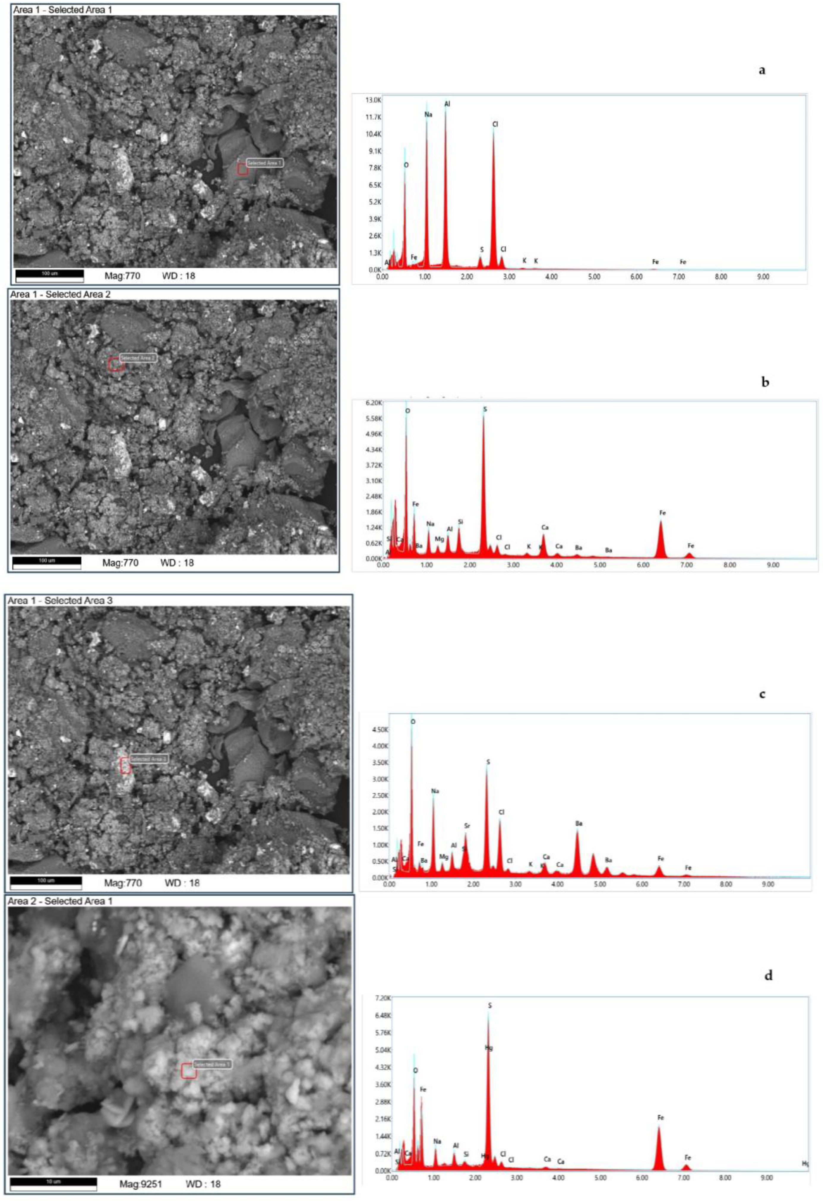
Figure 3 show the scanning electron microscopy (SEM) and elemental analysis results of the tank oil sludge samples.
Prior to analysis, the untreated (original oil sludge) and refined reservoir oil sludge (liquid) and residual solids (solid oil sludge) were dried on a thermal balance, resulting in weight losses of 26.9% (for untreated oil), 62.87% (for refined oil), and 14.65% (for residue), mainly due to volatile hydrocarbons impregnating the sludges.
Figure 1a,b show micrographs of the untreated reservoir oil sludge. The untreated samples of reservoir oil sludge contained solid particles. The elemental composition of individual sections of the reservoir oil sludge contained inorganic elements (Figure 1c). Both organic and inorganic elements were present on the surface of the solid particles of oil sludge Figure 1d.
Table 2 shows the qualitative elemental composition of the untreated oil sludge, obtained using SEM analysis. All experiments were carried out three times, and the average results are shown. As can be seen from the results, the main component is oxides. Specifically, BaO and SO3 are the most common compounds and K2O and MgO are the least common. Among these oxides, we can see chlorine in the amount of 5.9%.
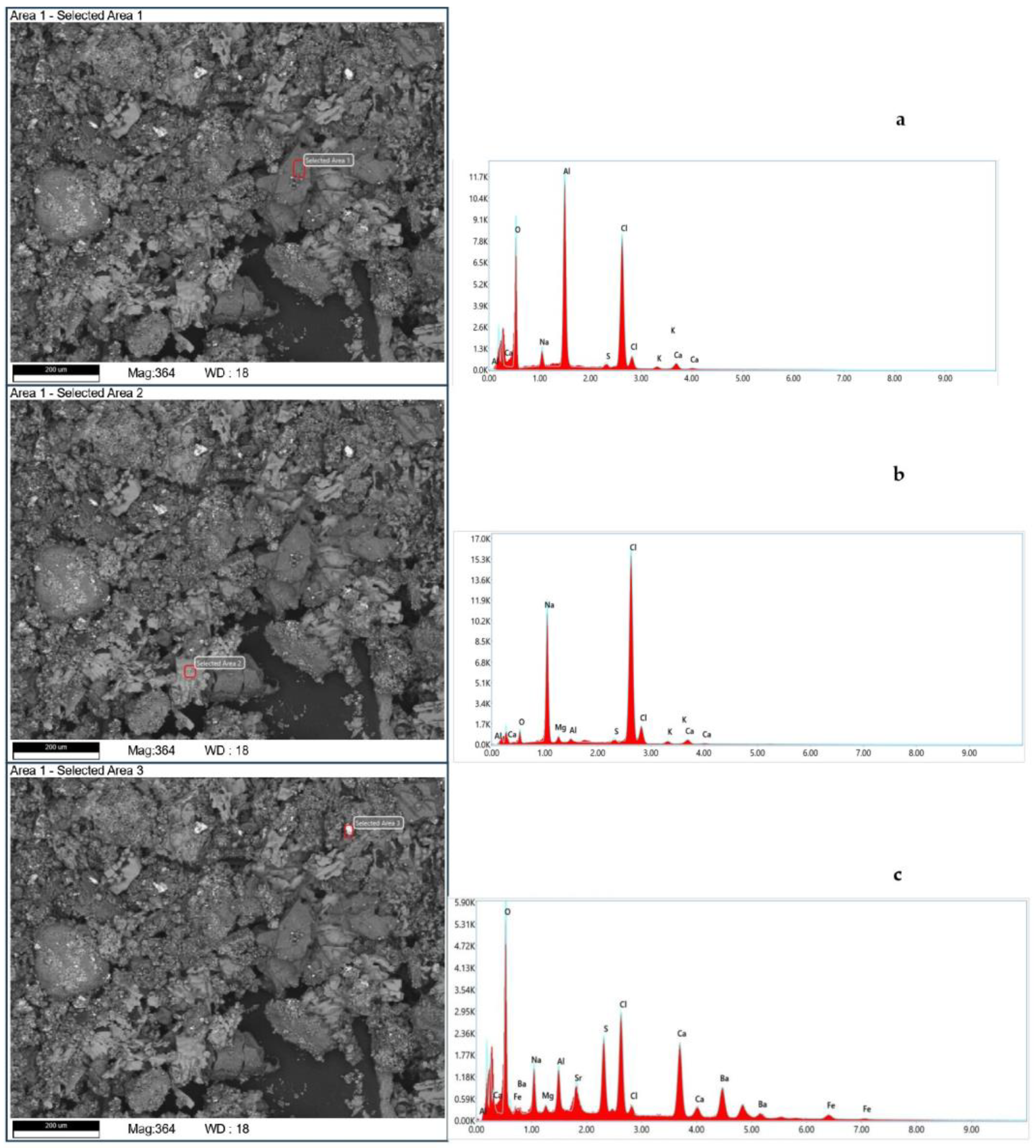
Figure 2 shows scanning electron micrographs of the purified tank oil sludge and the elemental analysis. Figure 2a,b show the surfaces of the purified tank oil sludge. The surface of purified tank oil sludge shown in Figure 2c is without features.
However, we cannot see a significant difference between them in terms of their morphological structure. The qualitative elemental composition results for this oil sludge are recorded in Table 3.
Table 3 shows the mean results of the elemental composition of the purified sample, as obtained by SEM analysis. As can be seen from the qualitative elemental analysis, after purification, most inorganic salt impurities were eliminated. The main salts remaining included Al, Cl, and oxides.
The process of cleaning the tank oil sludge from container impurities was carried out by vacuum filtration. 
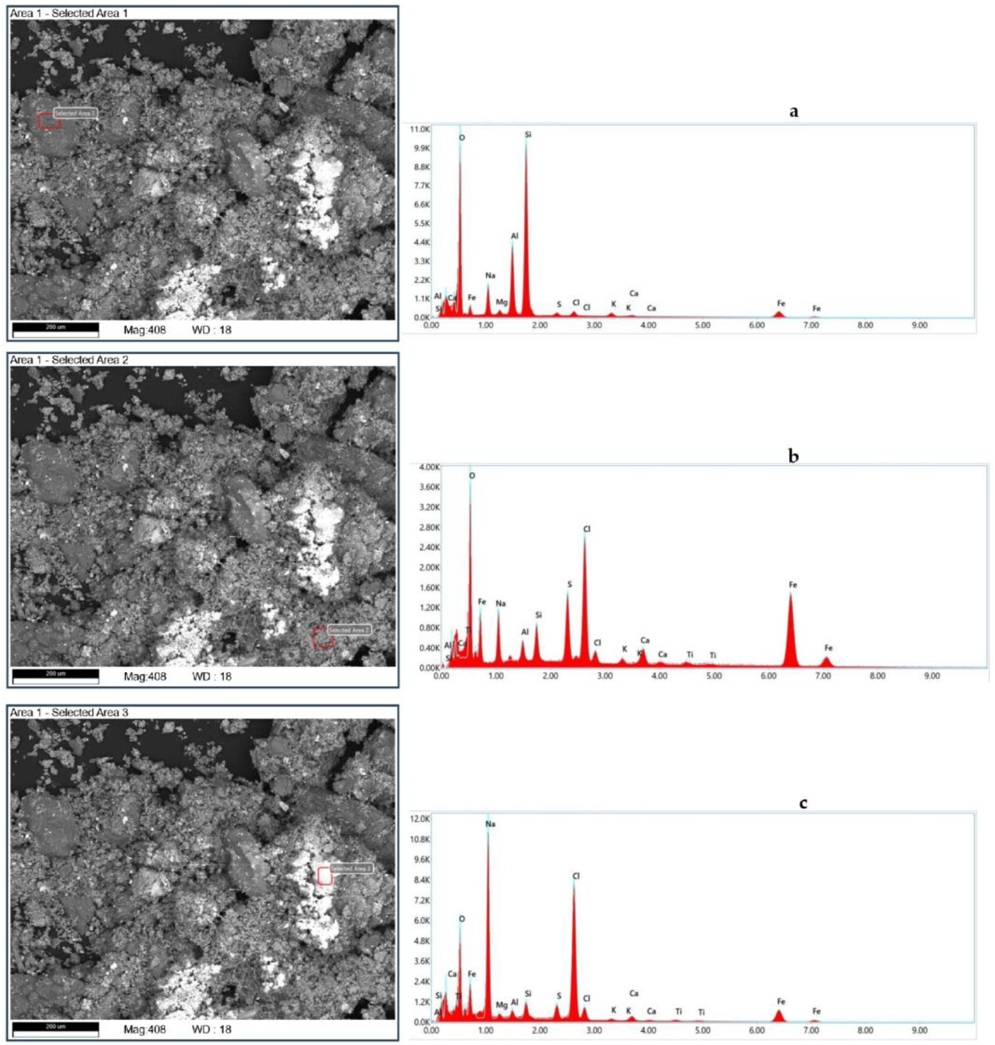
Figure 3 shows images of the mechanical particles obtained using a microscope scan and elementary analysis. Figure 3a shows the surface of the mechanical particles. Figure 3b,c show the morphological structure of harder particles.
Table 4 shows the mean results of the elemental composition of the mechanical impurities of the sample after the purification process, as obtained by SEM analysis. All three samples were composed of a clay matrix of silicoaluminates with particles of 100–200 μm in diameter.
The samples’ composition was characterized mainly by inorganic salts such as sulphates, pyrite, oxides (aluminum, sodium, iron, barium, calcium, strontium), and chlorides (mainly aluminum and sodium), whose origin can be attributed to soil alteration near lakes of a brackish character.
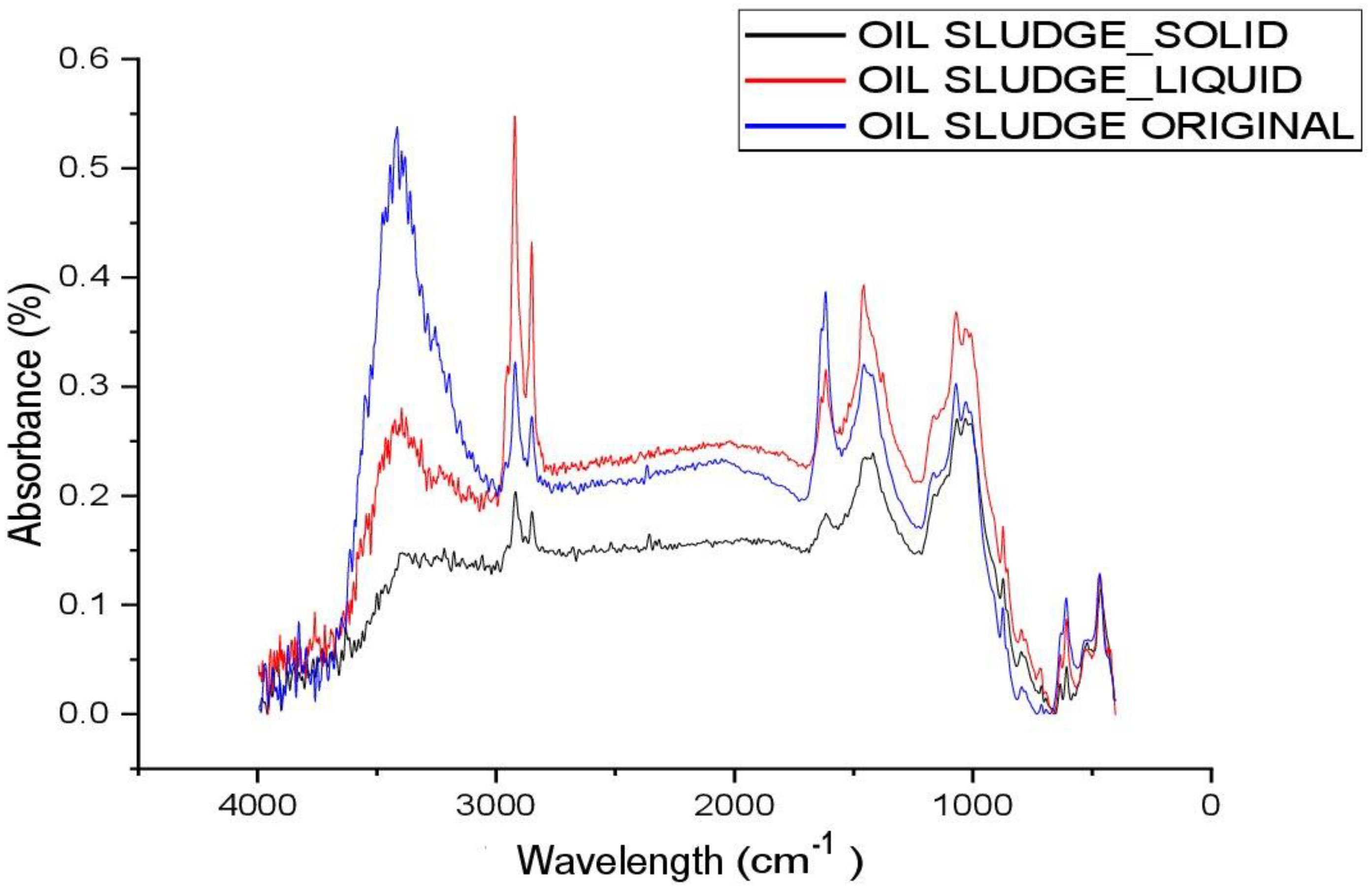
Figure 4 shows the FT-IR results of the untreated (original oil sludge) and purified tank oil sludge (liquid) and the mechanical impurities (solid oil sludge). In the IR spectra of the samples in Figure 4, an absorption band is observed at 3416 cm−1, characteristic of free acidic hydroxyl groups. The absorption peaks at 2922 and 2846 cm−1 are due to the bound hydroxyl groups of carboxylic acids. Low-intensity absorption bands in the region of 1618 cm−1 are attributed to vibrations of condensed aromatic hydrocarbons. It should be noted that the absorption bands at 608 cm−1 are quite high in intensity, which appear due to stretching vibrations of methyl groups. The low intensity of absorption bands in the region of 1704 and 1606 cm−1 is due to condensed aromatic hydrocarbons; such absorption bands belong to arylalkyl ketones (Ar-CO-R) and represent stretching vibrations of C-O-C and C-OH in carboxyl groups. Absorption bands with average intensity compared to natural bitumen deposit in the region of 1455 and 1376 cm−1 belong to vibrations of methyl groups and characterize the degree of branching of paraffins. The wide absorption band at 1000 cm−1 of high intensity is due to the presence of Si-O-Si bonds of the mineral part of the rock or S-O sulfoxide groups. Absorption bands in the range of 775–645 cm−1 clearly indicate monosubstituted aromatic structures in the composition of asphaltenes, resins, and asphaltogenic acids [25].
The tables below show the correspondence between functional groups and I, their corresponding peaks found in the IR spectra. As can be seen from Table 5, the spectra of the three analyzed samples have the same functional groups, with the exception of the peak related to the stretching of the OH group in the solid oil sludge sample.
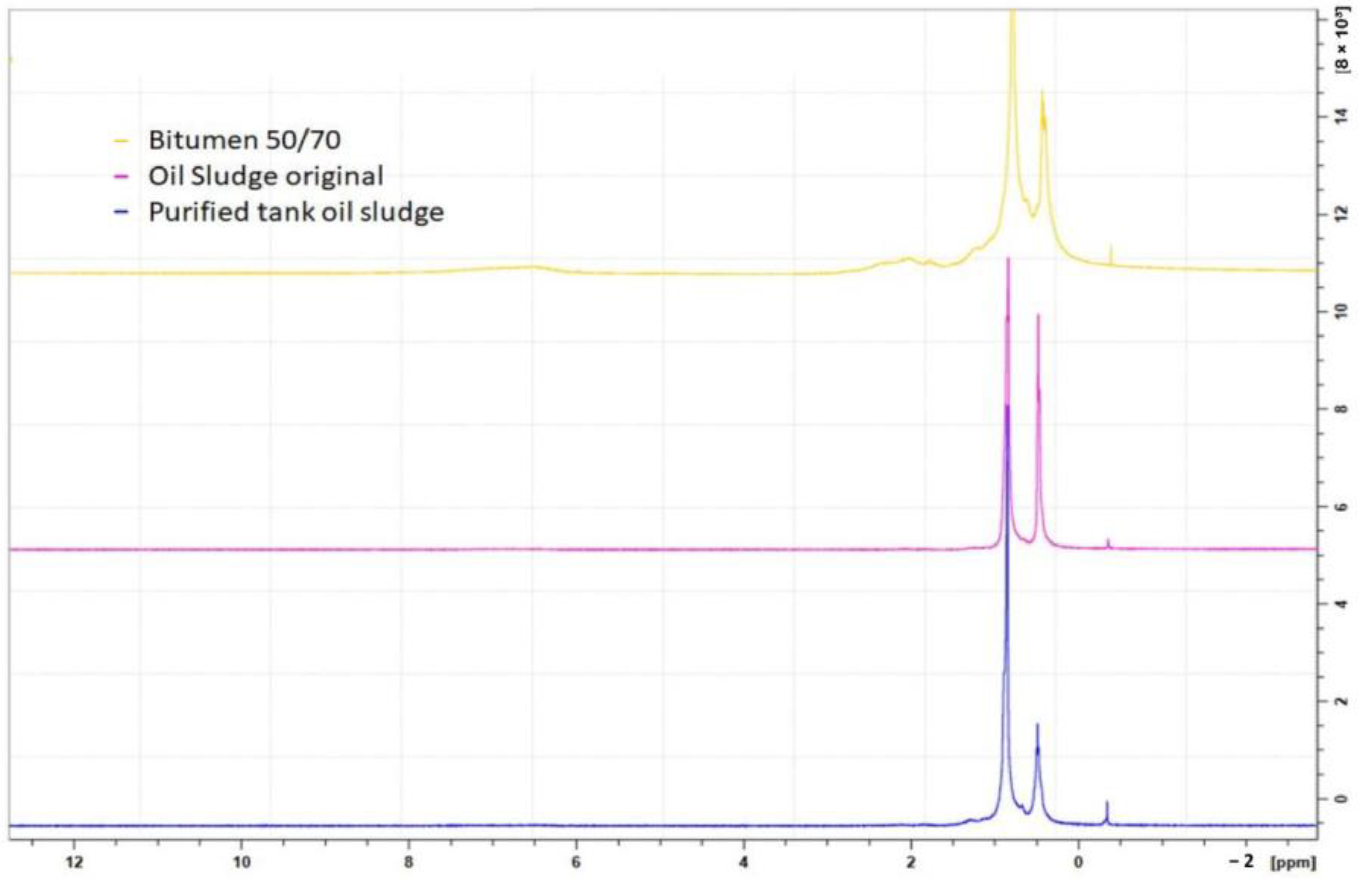
The spectra in Figure 5 are 1H NMR spectra of crude and treated tank oil sludge samples, in which two signals are visible in the aliphatic region, indicating that the oil sludge samples contain mainly this type of hydrocarbon while in the aliphatic zone.
The qualitative and quantitative compositions of the distillation products before and after ultrasonic treatment were determined by chromatographic analysis. The chromatographic analysis results of the samples are presented in Table 6, Table 7 and Table 8.
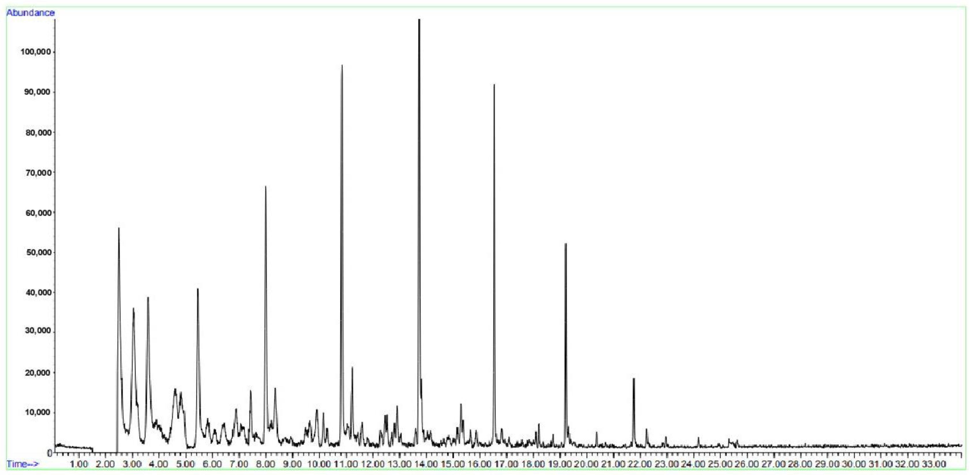
Table 6 presents the results of distillation of oil sludge from tank No. 1. Sample No. 2 of tank oil sludge was treated with ultrasound after mixing with a solvent. It has been established that oil sludge is a multicomponent mixture consisting of paraffin-naphthenic series substances and aromatic hydrocarbons, the intense peaks of which appear with a release time from 3 to 16 min (Figure 6).
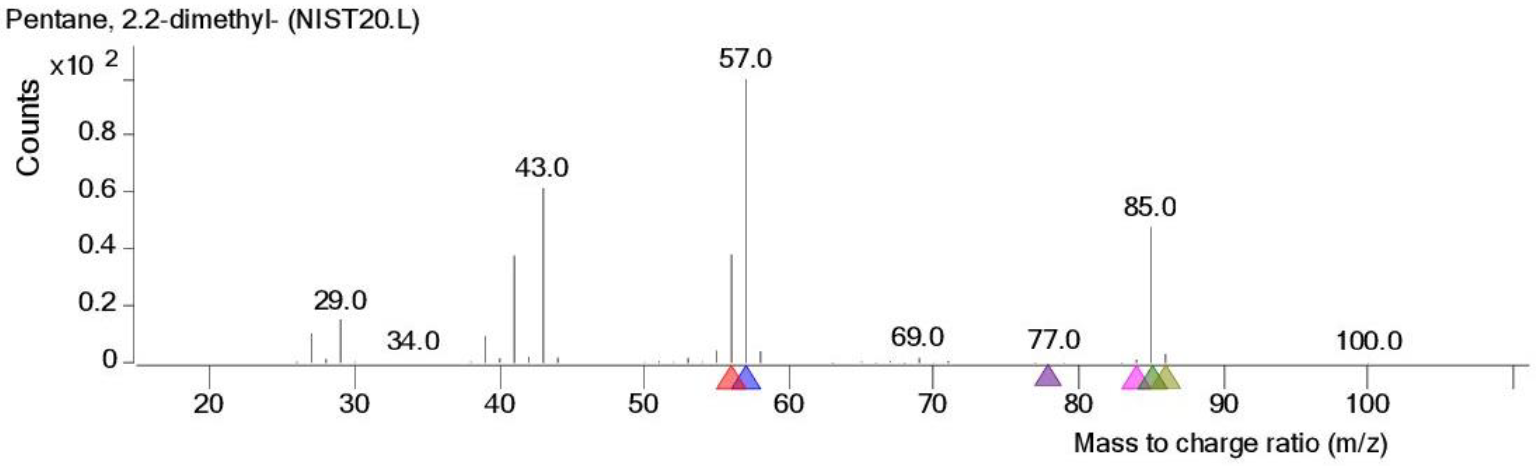
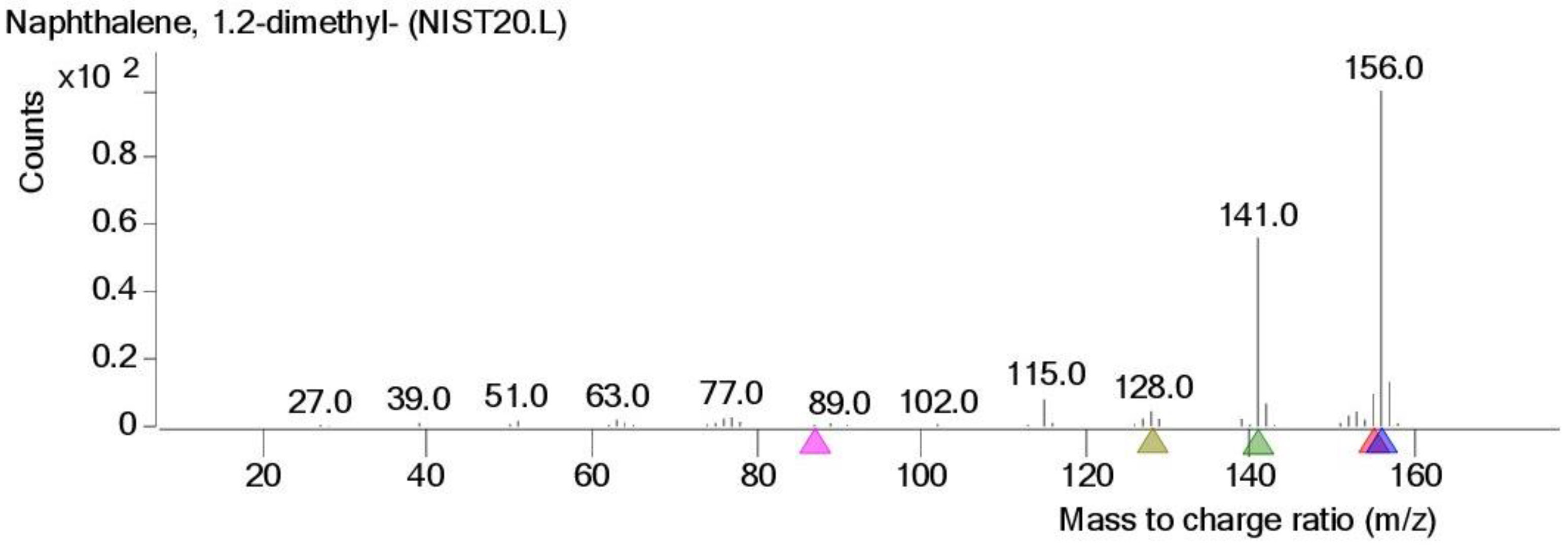
The study of the influence of ultrasonic treatment and the choice of mode on the composition of oil sludge from distillation products was carried out by studying the yield of individual low-molecular hydrocarbons. In order to clarify the effect of ultrasonic treatment, hydrocarbons such as cyclohexane, octane, 2,2-dimethylpentane, and naphthalene were studied in different modes and temperature conditions. We also studied the total yield of light fractions.
In order to determine the potential for the yield of light oil products, atmospheric distillation of the bottom sediments of oil reservoirs was carried out.
From the data in Table 7, it is clear that during storage, the fractional composition of the oil sludge changed; the content of light fractions decreased and the content of high-boiling fractions increased due to the formation of complex molecules with a high content of heavy polycyclic aromatic hydrocarbons and resinous asphaltene substances. There was a small amount of normal paraffin hydrocarbons, which is also evidenced by the gelatinous-mastic structure of the oil sludge from sludge reservoirs. The group and fractional composition indicates the presence of resins, paraffin-naphthenic hydrocarbons, and heavy aromatic polycyclic hydrocarbons.
In the sonicated sample, the main identifiable components were alkanes of normal and isomeric [29] structure, as well as some representatives of polycyclic aromatic compounds. At the first stage of analysis, the concentrations of non-alkane compounds in the final extract were significant.
Table 8 presents the products of the third fraction, obtained at temperatures of 180–220 °C. Yields of hexylcyclohexane and pentylcyclohexane in the products increased during ultrasonic treatment. Light hydrocarbons and their isomers also predominated in the distillation products. When the temperature increased to 225 °C and above, a light beige liquid consisting of 25 wt.% heavy paraffin was distilled.
Figure 6 shows a chromatogram of the distillation products of oil sludge treated with ultrasound, obtained by GC–MS. As shown in Figure 6, all components were released in up to 18 min, and naphthalene and its isomers were not present in the distillation products.
According to the obtained analyses, it is clear that exposure to ultrasound has a beneficial effect on the composition of oil sludge. Naphthalene acts as a carcinogenic agent in the environment and in humans, which affects the liver and the nervous system, and can cause cataracts and retinal hemorrhage. Naphthalene and its isomers as volatile substances increase the risk of development of laryngeal and colorectal cancers.
It has been experimentally established that ultrasonic treatment of tank oil sludge, when heated to 60 °C, enhances the effect of destruction of high-molecular-weight hydrocarbons and their interaction. According to the GC and mass spectrometric analysis, during the distillation of the ultrasonic-treated oil sludge extract, an increase in the yield of cyclohexane, octane, and 2,2-dimethylpentane and a decrease in the yield of naphthalene were observed.
At a frequency of 100 kHz for 30 min, ultrasonic treatment helps convert the composition of hydrocarbons into light hydrocarbons. Without ultrasonic treatment, the destruction of the structure of naphthalene and its derivatives begins at a distillation temperature of 450 °C. In addition, in samples treated with ultrasound at temperatures from 350 to 380 °C, the yield of naphthalene decreases to 3% of the total mass of hydrocarbons.
Figure 7, Figure 8 and Figure 9 show the spectra of individual hydrocarbons.
From these studies, it follows that tank oil sludge contains a large amount of heavy polycyclic aromatic hydrocarbons. The optimal conditions for ultrasonic treatment [30] of barn oil sludge have been determined as a duration of 30 min at 100 kHz, which increases the yield of light hydrocarbons during the process [18] of atmospheric distillation. It has been established that ultrasonic treatment reduces the yield of heavy polycyclic aromatic hydrocarbons. Polycyclic aromatic hydrocarbons decompose into smaller aromatic hydrocarbons. With an increase in the power of ultrasonic treatment, the yield of hydrocarbon isocompounds decreases.

4. Conclusions

The method of processing and disposing of oil sludge requires enhanced control since the problem of its use has not been solved in production conditions [31]. The lack of separate collection and storage of oil sludge is a big problem. By separately storing oil sludge depending on the composition [32] at the stage of formation, groups of waste suitable for recycling can be distinguished. Further, the processing of mixed and old oil sludge requires additional purification.
In this work, the purification of tank oil sludge from mechanical impurities was carried out. The composition of mechanical impurities in the oil sludge was studied.
During extraction with hexane, medium and lighter hydrocarbons passed into the solution. During extraction in a mixture of hexane and benzene, depending on the ratio, heavy aromatic hydrocarbons and their derivatives were extracted. Ultrasonic treatment increased the selectivity of the formation of hydrocarbon isocompounds and promoted the maximum yield of light hydrocarbon fractions as motor fuels.
The optimal conditions for ultrasonic treatment of tank oil sludge were determined as a duration of 30 min at 100 kHz, which increased the yield of light hydrocarbons during atmospheric distillation. It has been established that ultrasonic treatment reduces the yield of heavy polycyclic aromatic hydrocarbons, which decompose into smaller aromatic hydrocarbons.
The residual high-carbon mass is less carcinogenic since many heavy hydrocarbons are removed during extraction.
A study of the composition of the oil sludge was carried out in laboratory conditions using the methods of chromatography and mass spectrometry, and the physicochemical properties of the oil sludge were studied in order to select the most effective method of processing in order to obtain secondary products.
Fractions obtained at temperatures of 65 and 85 °C were used, with 200 g employed to dissolve a new portion of tank oil sludge for processing. Fractions obtained at temperatures of 120 and 180 °C can be used as light motor fuel. In distillation products at a temperature of 180 °C, the yield of isocompounds was 20.5%, and at a temperature of 220 °C—17.2%. In the following fractions synthesized at temperatures of 230–330 °C, naphthenes were found in large quantities. In fractions obtained at temperatures of 350 °C and above, polycyclic aromatic hydrocarbons predominated.

Author Contributions

Writing—original draft preparation, S.T.; project administration and funding acquisition, A.T.; investigation, C.O.R. and M.P.; methodology, D.T. and P.C.; formal analysis, K.T. and E.K.; data curation, Y.T.; writing—review and editing, N.Z. All authors have read and agreed to the published version of the manuscript.

Funding

This research was funded by the Committee of Science of the Ministry of Science and Higher Education of the Republic of Kazakhstan, under the following grant number and title: BR24992915, “Development of technologies for producing high-strength asphalt concrete based on elastomeric-, polymer-bitumen binders and plasma-chemical processing of liquid carbon-containing waste” (2024–2026).

Data Availability Statement

The original contributions presented in the study are included in the article, further inquiries can be directed to the corresponding author.

Conflicts of Interest

The authors declare no conflict of interests.

References

  1. Akhmetshin, M.R. Reduction of Concentrations of Sulfur and Nitrogen Oxides During Combustion of Waste from Oil Production and Oil Refining in the Composition of Composite Liquid Fuels. Ph.D. Thesis, National Research Tomsk Polytechnic University, Tomsk, Russia, 2023; 142p. (In Russian). [Google Scholar]
  2. Tanirbergenova, S.; Ongarbayev, Y.; Tileuberdi, Y.; Zhambolova, A.; Kanzharkan, E.; Mansurov, Z. Selection of Solvents for the Removal of Asphaltene–Resin–Paraffin Deposits. Processes 2022, 10, 1262. [Google Scholar] [CrossRef]
  3. Kudaybergenov, K.K.; Ongarbayev, E.K.; Mansurov, Z.A. Petroleum sorption by thermally treated rice husks derived from agricultural byproducts. Eurasian Chem. Technol. J. 2013, 15, 57–66. [Google Scholar] [CrossRef]
  4. Kudaibergenov, K.; Ongarbayev, Y.; Mansurov, Z.; Tulepov, M.; Tileuberdi, Y. Rice husk ash for Oil Spill cleanup. Appl. Mech. Mater. 2014, 446–447, 1508–1511. [Google Scholar] [CrossRef]
  5. Yaroslavtseva, A.A. Assessing the Effectiveness of Using Thermal Methods in the Processing of Oil-Containing Waste. Master’s Thesis, Togliatti State University, Tolyatti, Russia, 2019; 97p. (In Russian). [Google Scholar]
  6. Yagafarova, G.G.; Ilyina, E.G.; Leontieva, S.V.; Yagafarov, I.R.; Safarov, A.H. Method for Cleaning Oil Sludge from Oil and Petroleum Products. Patent RU No. 2332362C2, 27 August 2008. (In Russian). [Google Scholar]
  7. Samigullina, L.M. Analysis of the composition and sources of formation of oil sludge at oil refineries. Young Sci. 2022, 48, 70–73. (In Russian) [Google Scholar]
  8. Kamali, A.; Heidari, S.; Golzary, A.; Tavakoli, O.; Wood, D.A. Optimized catalytic pyrolysis of refinery waste sludge to yield clean high quality oil products. Fuel 2022, 328, 125292. [Google Scholar] [CrossRef]
  9. Gan, Z.; Zhao, C.; Li, Y.; Chen, G.; Song, Z.; Zhang, Z.; Ran, W. Experimental investigation on smoldering combustion for oil sludge treatment: Influence of key parameters and product analysis. Fuel 2022, 316, 123354. [Google Scholar] [CrossRef]
  10. Farzadkia, M.; Dehghani, M.; Moafian, M. The effects of Fenton process on the removal of petroleum hydrocarbons from oily sludge in Shiraz oil refinery. Iran. J. Environ. Health Sci. Eng. 2014, 12, 31. [Google Scholar] [CrossRef]
  11. Khan, M.K.; Sarkar, B.; Zeb, H.; Yi, M.; Kim, J. Simultaneous breaking and conversion of petroleum emulsions into synthetic crude oil with low impurities. Fuel 2017, 199, 135–144. [Google Scholar] [CrossRef]
  12. Khan, M.K.; Kwek, W.; Kim, J. Conversion of petroleum emulsion into light fraction-rich upgraded oil in supercritical methanol. Fuel 2018, 218, 78–88. [Google Scholar] [CrossRef]
  13. Khan, M.K.; Cahyadi, H.S.; Kim, S.; Kim, J. Efficient oil recovery from highly stable toxic oily sludge using supercritical water. Fuel 2019, 235, 460–472. [Google Scholar] [CrossRef]
  14. Wang, J.; Lai, Y.; Wang, X. Advances in ultrasonic treatment of oily sludge: Mechanisms, industrial applications, and integration with combined treatment technologies. Environ. Sci. Pollut. Res. 2024, 31, 14466–14483. [Google Scholar] [CrossRef] [PubMed]
  15. Thong, O.; Ibrahim, A.; Rahim, H.A.; Jun, Y.W.; Ismail, N. A Review of Crude Oil Recovery Methods from Petroleum Sludge. Int. J. Eng. Technol. Sci. 2021, 8, 40–50. [Google Scholar] [CrossRef]
  16. Aliyev, G.; Hajiyeva, R.; Ahmadova, E.; Imanova, T.; Rahimov, M. Analysis of Physico-Chemical Methods for Investigation of Oil Sludge. J. Surv. Fish. Sci. 2023, 10, 826–830. [Google Scholar] [CrossRef]
  17. Hui, K.; Tang, J.; Lu, H.; Xi, B.; Qu, C.; Li, J. Status and prospect of oil recovery from oily sludge: A review. Arab. J. Chem. 2020, 13, 6523–6543. [Google Scholar] [CrossRef]
  18. Hu, G.; Li, J.; Huang, S.; Li, Y. Oil recovery from petroleum sludge through ultrasonic assisted extraction. Journal of Environmental Science and Health Part A. Toxic Hazard. Subst. Environ. Eng. 2016, 51, 921–929. [Google Scholar] [CrossRef]
  19. Ongarbaev, E.K.; Imanbaev, E.I.; Tileuberdi, E.; Golovko, A.K. Extraction of natural bitumen from oil-bituminous rocks of the Beke and Munaily Mola fields. Combust. Plasma Chem. 2017, 65, 148–155. (In Russian) [Google Scholar]
  20. Al-Doury, M.M.I. Treatment of oily sludge using solvent extraction. Pet. Sci. Technol. 2019, 37, 190–196. [Google Scholar] [CrossRef]
  21. Luo, X.; Gong, H.; He, Z.; Zhang, P.; He, L. Research on mechanism and characteristics of oil recovery from oily sludge in ultrasonic fields. J. Hazard. Mater. 2020, 399, 123137. [Google Scholar] [CrossRef]
  22. Zubadylda, A.S. Study of the chemical composition of a thick extract of chickweed (Stellaria media L.). Curr. Res. 2024, 12, 58–64. (In Russian) [Google Scholar]
  23. Roussis, S.G.; Andrew, S.C. Simplified Hydrocarbon Compound Type Analysis Using a Dynamic Batch Inlet System Coupled to a Mass Spectrometer. Energy Fuels 1997, 11, 879–886. [Google Scholar] [CrossRef]
  24. Bechar, S.; Zerrouki, D. Effect of natural pozzolan on the fresh and hardened cement slurry properties for cementing oil well. World J. Eng. 2018, 15, 513–519. [Google Scholar] [CrossRef]
  25. Zhang, Y.; Zhao, H.; Shi, Q.; Chung, K.; Zhao, S.; Xu, C. Molecular Investigation of Crude Oil Sludge from an Electric Dehydrator. Energy Fuels 2011, 25, 3116–3124. [Google Scholar] [CrossRef]
  26. Rossi, C.O.; Caputo, P.; De Luca, G.; Maiuolo, L.; Eskandarsefat, S.; Sangiorgi, C. 1H-NMR spectroscopy: A possible approach to advanced bitumen characterization for industrial and paving applications. Appl. Sci. 2018, 8, 229. [Google Scholar] [CrossRef]
  27. GB/T 511-2010; Petroleum Products and Additives. Method for Determination of Mechanical Admixtures. Interstandard (Russia): Sydney, Australia, 2013.
  28. ASTM D6304-16; Standard Test Method for Determination of Water in Petroleum Products, Lubricating Oils, and Additives by Coulometric Karl Fischer Titration. American Society for Testing and Materials: West Conshohocken, PA, USA, 2016.
  29. Efimov, I.I. Physico-Chemical Description of the Equilibria of Condensed Phases in Hydrocarbon Systems with the Participation of Polycyclic Compounds. Ph.D. Thesis, Saint Petersburg Mining University, Saint Petersburg, Russia, 2023; 153p. [Google Scholar]
  30. Baygaziev, M.T. Enhanced Oil Recovery at the Late Stage of Field Development and Destruction of Oil Sludge with Hydroreacting Compounds. Ph.D. Thesis, Satbayev University, Almaty, Kazakhstan, 2019; 127p. (In Russian). [Google Scholar]
  31. Shperber, D.R. Development of Resource-Saving Technologies for Oil Sludge Processing. Ph.D. Thesis, Kuban State Technological University, Kuban, Russia, 2014. (In Russian). [Google Scholar]
  32. Gorbaev, A.V. Improving the chemical method of recycling oil sludge by dissolving it in petroleum distillates. XXI Century. Technosphere Saf. 2019, 4, 98–107. (In Russian) [Google Scholar] [CrossRef]
Figure 1. Micrographs of untreated tank oil sludge: (a,b) surface of untreated tank oil sludge; (c) surface of untreated tank oil sludge with mechanical impurities; (d) surface of monolithic particles with oil sludge.
Processes 12 02007 g001
Figure 2. Micrographs of purified tank oil sludge: (a,b) micrograph of purified tank oil sludge; (c) surface of dense part of purified tank oil sludge.
Processes 12 02007 g002
Figure 3. Micrographs of mechanical particles obtained during the process of cleaning reservoir oil sludge: (a) micrograph of mechanical impurities of reservoir oil sludge; (b,c) micrographs of small mechanical impurities of reservoir oil sludge.
Processes 12 02007 g003
Figure 4. FT-IR of untreated (original oil sludge) and purified tank oil sludge (liquid) and mechanical impurities (solid oil sludge).
Processes 12 02007 g004
Figure 5. NMR spectra of samples of untreated and purified tank oil sludge.
Processes 12 02007 g005
Figure 6. Chromatogram of the results of distillation of pit oil sludge.
Processes 12 02007 g006
Figure 7. Mass spectrum of cyclohexane.
Processes 12 02007 g007
Figure 8. Mass spectrum of octane.
Processes 12 02007 g008
Figure 9. Mass spectrum of naphthalene.
Processes 12 02007 g009
Table 1. Composition of the studied oil sludge samples.
NameMechanical ImpuritiesOrganic PartWaterOthers
Bottom sediments of oil reservoirs, %6.4866.21.4
Table 2. Untreated oil sludge qualitative analysis result.
Element Mean Weight, %
Na2O10.8 ± 0.1
MgO1.3 ± 0.1
Al2O32.7 ± 0.1
SiO21.7 ± 0.1
SO323.5 ± 0.1
Cl5.9 ± 0.1
K2O0.5 ± 0.1
CaO3.0 ± 0.1
FeO7.1 ± 0.1
SrO7.2 ± 0.1
BaO36.3 ± 0.1
Table 3. Purified oil sludge qualitative analysis result.
Element Mean Weight, %
Na2O6.6 ± 0.1
MgO0.9 ± 0.1
Al2O36.2 ± 0.1
SO317.9 ± 0.1
Cl11.7 ± 0.1
CaO20.8 ± 0.1
FeO3.5 ± 0.1
SrO6.3 ± 0.1
BaO26.1 ± 0.1
Table 4. Qualitative analysis result of oil sludge residue after purification.
Element Mean Weight, %
Na2O38.3 ± 0.1
MgO1.5 ± 0.1
Al2O32.2 ± 0.1
SiO24.6 ± 0.1
SO36.3 ± 0.1
Cl26.7 ± 0.1
K2O0.6 ± 0.1
CaO2.2 ± 0.1
TiO21.0 ± 0.1
FeO16.8 ± 0.1
Table 5. Results of FT-IR of crude tank oil sludge (original oil sludge), purified tank oil sludge (liquid), and mechanical impurities (solid oil sludge).
Original Oil SludgeLiquid Oil SludgeSolid Oil Sludge
Stretching OH alcohol3416 cm−1 Stretching CH alkane2916 cm−1
Stretching CH alkane2922 cm−1Stretching CH alkane2922 cm−1Stretching CH alkane2852 cm−1
Stretching CH alkane2846 cm−1Stretching CH alkane2850 cm−1C=C alkene1618 cm−1
C=C alkene1618 cm−1C=C alkene1616 cm−1Bending CH alkane1450 cm−1
Bending CH alkane1452 cm−1Bending CH alkane1459 cm−1S-O1063 cm−1
S-O (or C-OH)1071 cm−1S-O (or C-OH)1067 cm−1S-O1026 cm−1
Bending CH608 cm−1Bending CH608 cm−1Bending CH610 cm−1
Table 6. Results of chromatographic analysis.
Component CompositionContent, %
Sample CodeNo. 1No. 2
Paraffins43.4252.47
Uncondensed cycloparaffins23.7745.09
Condensed cycloparaffins with 2 rings12.240
Condensed cycloparaffins + all 3-ring cycloparaffins1.572.44
Benzenes16.230
Naphthenobenzenes00
Dinaphthenobenzenes0.180
Mothballs1.870
Acenaphthenes0.470
Fluorenes0.250
Phenanthrene00
Table 7. Results of atmospheric distillation of bottom sediments of reservoir oil sludge.
Name of Fraction, °CFraction Yield, wt. %
Untreated Tank Oil SludgeUltrasonic Treated Tank Oil Sludge
65–8020–2218–19
80–10015–1715–17
100–12510–1215–12
125–18011–1018–19
180–25011–1219–20
250–32012–148–9
320–38010–115–6
380–4509–103–5
450–5008–92–3
Table 8. Results of chromatographic analysis of tank oil sludge.
No. Retention Time, minConnectionsProbability of Identification, %Percentage Content, %
19.48Benzene, 1-ethyl-4-methyl-881.97
210.00Undecane9621.05
310.39Benzene, 1-ethyl-3-methyl-887.24
411.42Undecane, 2,6-dimethyl-771.02
511.62Benzene, (1,3,3-trimethylnonyl)-763.26
612.02Cyclohexane, pentyl-772.16
712.13Benzene, 1-ethyl-2,3-dimethyl-741.23
812.81Dodecane9418.59
913.13Benzene, 1-methyl-2-(1-methylethyl)-741.18
1013.91Naphthalene, decahydro-1,5-dimethyl-781.06
1114.11Benzene, 4-ethyl-1,2-dimethyl-660.84
1214.22Cyclohexane, 2-butyl-1,1,3-trimethyl-770.93
1314.35Nonane, 3-methyl-652.43
1414.42Dodecane, 2-methyl-861.18
1514.93Cyclohexane, hexyl-811.07
1615.58Tridecane9212,51
1715.851,1,6,6-Tetramethylspiro[4,4]nonane670.88
1817.24Dodecane, 2,6,10-trimethyl-881.17
1917.39Tridecane, 3-methyl-730.31
2017.76Heptylcyclohexane720.78
2118.24Tetradecane966.76
2218.35Naphthalene911.68
2319.39Hexadecane, 2,6,10,14-tetramethyl-800.96
2419.71Tetradecane, 2-methyl-750.33
2520.67Decahydro-4,4,8,9,10-pentamethylnaphthalene700.49
2620.77Pentadecane944.02
2721.251H-Indene, 1-ethylidene-921.30
2821.87Decahydro-4,4,8,9,10-pentamethylnaphthalene830.38
2921.98Naphthalene, 2-methyl-890.66
3023.18Hexadecane931.52
3124.64Naphthalene, 1,7-dimethyl-900.51
3225.46Heptadecane880.52
Disclaimer/Publisher’s Note: The statements, opinions and data contained in all publications are solely those of the individual author(s) and contributor(s) and not of MDPI and/or the editor(s). MDPI and/or the editor(s) disclaim responsibility for any injury to people or property resulting from any ideas, methods, instructions or products referred to in the content.

