Article

Numerical Simulation of Rock Cracking Using Saddle Polycrystalline Diamond Compact Cutters Considering Confined Pressure and Mechanism of Speed Increase

College of Mechanical Engineering, Xi’an Shiyou University, Xi’an 710065, China
*
Author to whom correspondence should be addressed.
Processes 2024, 12(7), 1450; https://doi.org/10.3390/pr12071450
Submission received: 18 June 2024 / Revised: 8 July 2024 / Accepted: 10 July 2024 / Published: 11 July 2024
(This article belongs to the Section Manufacturing Processes and Systems)

Abstract

:
Geothermal energy, recognized as a clean energy source, has attracted widespread attention for its extraction. However, it is located in deep and complex geological formations, presenting a significant challenge to the drilling operations of existing Polycrystalline Diamond Compact (PDC) drill bits. To further understand the rock-breaking mechanism of PDC cutters in deep geological formations and improve rock-breaking efficiency, a finite element model employing the cohesive zone method was developed for a saddle-shaped PDC cutter (SC). This model was validated against experimental simulations, proving its capability to capture real rock crack initiation during the simulation process accurately. By analyzing the formation of cracks under cutting forces, the SC’s rock-breaking mechanism was explored and compared with conventional cutters (CCs), clarifying its advantages. Additionally, the model analyzed the effects of different confined pressures, back rake angles, and structural parameters on crack formation in SC rock-breaking, highlighting directions for structural optimization. Full-scale drill bit rock-breaking simulations were conducted to verify the effectiveness and optimization of single cutter usage. The results indicated that the total number of cracks and the generation of tensile cracks determine the rock-breaking efficiency of the cutter. A lower total number of cracks and a higher proportion of tensile cracks lead to better rock-breaking performances. Due to its unique ridged and curved structure, the SC can generate concentrated and tensile stresses on the rock more effectively, resulting in fewer total cracks and a higher proportion of tensile cracks. The increase in confined pressure suppresses the generation of tensile cracks during rock-breaking, dispersing the rock-breaking energy, increasing the total number of cracks, and reducing rock-breaking efficiency. However, under the same conditions, using SC can effectively address these issues and enhance efficiency. For deep formation drilling, a back rake angle range of 15° to 20° is recommended for SC. The arc radius significantly impacts the SC’s tensile cracks and total number of cracks, with a recommended arc radius range of 50 mm to 60 mm, and the SC structure could be modified from an arc to a straight line and back to an arc. The results contribute to enhancing the efficiency of deep drilling and theoretical research on drill bits.

1. Introduction

Geothermal energy represents a renewable and clean source of power. Statistics indicate that the carbon emissions from generating electricity via geothermal energy are approximately 95% lower than those produced by traditional coal-fired power generation [1]. Furthermore, compared to other clean energy sources, such as wind and solar power, geothermal energy exhibits lower dependency on natural environmental conditions, offers reliable transmission, boasts strong stability, possesses a large and renewable reserve, and holds a broad application prospect [2]. Since the year 2000, China has rapidly advanced in the field of shallow geothermal energy development, ranking among the world leaders [3]. In recent years, however, progress in the development of geothermal energy in China has slowed. Meanwhile, international attention to geothermal energy development has been significant, leading to substantial advancements in geothermal energy development technologies in some countries. Therefore, it is imperative to prioritize the development of geothermal energy.
The geothermal gradient, which indicates an increase in temperature with depth, suggests that deeper geological formations have higher temperatures and, consequently, contain more geothermal energy, offering greater utilization and electricity generation efficiencies. However, exploiting geothermal resources in these deep formations entails deeper drilling, navigating complex geological environments, and enduring higher temperatures [4], posing substantial challenges to drilling tools, particularly PDC drill bits [5]. While traditional PDC bits exhibit a commendable efficiency and lifespan in soft and medium–hard formations, their performance in breaking rocks in deep and complex formations leaves much to be desired. Enhancing the rock-breaking efficiency and service life of PDC bits in such challenging conditions has emerged as a focal point of international attention.
It is well-known that as the basic cutting element of a drill bit, the performance of PDC cutters often determines the overall field effectiveness of the drill bit. In recent years, with the rapid development of manufacturing processes and research technologies, PDC cutters are no longer confined to flat structures. An increasing number of non-planar PDC cutter geometries designed for complex formations have been developed [6]. The axe-shaped cutter, a PDC cutter with an edge similar to an axe blade, reduces the contact area with the rock compared to conventional cutters [7]. It retains the traditional PDC cutter’s capability for shearing and fracturing rocks while also plowing through the rock. Thus, it offers higher efficiency and aggressiveness than conventional tools, along with greater wear resistance and longevity [8]. Shao et al. developed a multi-ridge PDC cutter based on the axe-shaped tooth structure. Through a simulation and experimental comparison with the axe-shaped cutter, their research demonstrated that the multi-ridge PDC cutter more effectively induces stress concentration in rocks, leading to breakage with less energy consumption, lower torque requirements, and enhanced wear resistance. The use of this tooth shape can increase rock-breaking efficiency by more than 100% compared to axe-shaped cutters [9]. The triangular PDC cutter, with its three-ridge structure, shares similar rock-breaking characteristics to the axe-shaped cutter but has a symmetrical construction, offering better wear resistance and stability during rock-breaking, along with higher rock-breaking efficiency [10]. Extensive research, through experimentation or numerical simulation—or a combination of both—has validated the effectiveness of the triangular PDC cutter [11,12,13]. The conical PDC cutter, with its spike-like structure, plows through the rock with point loads and also generates tensile stress in the rock, effectively enhancing rock-breaking efficiency. Moreover, it features a thicker polycrystalline diamond layer, offering improved impact resistance and high-temperature tolerance [14]. The rock-breaking effects and characteristics of the conical PDC cutter have been confirmed by numerous studies [15,16,17,18,19]. Beyond these common tooth geometries, others such as the fan-shaped cutter [20], multi-ridge-curved cutter [21], and wide-blade cutter have also achieved favorable results following their design [22], development, and mechanism studies by researchers. Liu et al., by simulating the process of various atypical PDC cutters fracturing heterogeneous granite, revealed the mechanisms by which different atypical cutters fracture heterogeneous granite. Additionally, they simulated the rock-breaking process of PDC drill bits using different atypical cutters and found that the saddle-shaped cutter had the highest rock-breaking efficiency, even significantly surpassing the axe-shaped and triangular cutters [23]. Consequently, the structural design of PDC cutters significantly impacts the drill bit’s rock-breaking due to the substantial differences in rock-breaking mechanisms among various cutter designs. Hence, studying the mechanisms of cutters during the rock-breaking process is of great importance, as it not only helps researchers understand the advantages of cutter rock-breaking but also facilitates the optimization of cutter structures and operational parameters, further enhancing cutter performance.
Both laboratory and field experimental studies provide accurate evaluations of the effectiveness of PDC cutters and, by extension, the entire drill bit. However, these methods often struggle to directly observe the interaction process between PDC cutters and rock, typically inferring the performance from post-drilling indicators, such as the size and weight of rock cuttings, traces of rock cutting, and wear conditions of the PDC cutters [20,24]. This approach may not fully encapsulate the rock-breaking characteristics of the cutters. Consequently, an increasing number of scholars have turned to combining finite element numerical simulations with experimental methods to analyze the rock-breaking characteristics of PDC cutters. Utilizing the finite element method to simulate the rock-breaking process of PDC cutters not only accurately reflects the cutting forces experienced by the cutters but also precisely evaluates the efficiency of the rock-breaking process, assessed by metrics such as mechanical specific energy (MSE) [1]. More importantly, this approach can provide real-time insights into the stress state of rock post-cutting, aiding significantly in the analysis of cutter rock-breaking characteristics [25]. For instance, He et al. compared the rock-breaking processes of triangular PDC cutters with conventional cutters using finite element simulation. Their findings indicate that, under identical operating parameters, triangular cutters enhance efficiency by shearing and crushing the rock, experiencing lower cutting forces than conventional cutters. Furthermore, they explored the rock-breaking patterns of triangular cutters, offering support for subsequent work and parameter optimization [11]. Ke and colleagues designed a three-dimensional concave PDC cutter specifically for the Weiyuan shale gas field, comparing its rock-breaking process with that of conventional cutters through finite element simulation and experimental methods. Their results show significant improvements in normal force, tangential force, and MSE for the three-dimensional concave PDC cutter, with the field application of this cutter increasing drilling penetration by 41.8% [26]. Beyond structural analysis, the finite element method can also simulate the temperature field during PDC cutter rock-breaking, enabling the real-time observation and analysis of temperatures [27,28]. Additionally, to accurately replicate the stress state of underground rocks, it is necessary to apply net water pressure and confined pressure to the rock—a task often challenging in experiments but conveniently achieved with finite element methods [29]. However, finite element methods struggle to simulate the initiation and propagation of cracks as PDC cutters penetrate the rock, even though understanding the micro-behaviors of crack initiation, propagation, and final fracturing under cutter action is crucial for analyzing cutter rock-breaking mechanisms. Therefore, some scholars opt for the Particle Flow Code (PFC) method to simulate crack initiation and propagation during rock cutting by cutters [30]. This method can simulate cracks, which are generated during rock fracturing, differentiate between tensile and shear cracks, and quantify cracks, providing valuable insights into the cutter’s rock-breaking mechanism [31]. However, using this method poses challenges in accurately determining certain rock parameters, requiring continuous adjustments. Moreover, it may not accurately simulate the cutting forces of cutters, and particle contacts may not update promptly at high cutting speeds, affecting the accuracy of simulating the cutter rock-breaking process [32].
With in-depth research conducted by some scholars, cohesive elements were introduced into finite element simulations [33]. These elements are zero-thickness, adhesive elements that can be embedded within predefined finite element meshes, allowing cracks to form in the mesh when external forces reach their damage thresholds. The introduction of cohesive elements successfully addresses the limitation of finite element methods in simulating crack propagation, filling a crucial gap in previous research. Several scholars have conducted studies utilizing cohesive elements, achieving significant results. Jiang et al., by incorporating cohesive elements into their finite element simulations, not only accurately captured the cracks generated during the uniaxial compression of rocks but also matched the numerical values of rock tensile strength with experimental data. Moreover, their numerical simulations revealed the initiation and propagation of cracks and the formation of rock chips when a conical PDC cutter was pressed into the rock under varying working parameters, aiding in the optimization design of conical cutters [33]. Similarly, Wang and others employed cohesive elements to simulate the fracturing of pre-grooved granite by PDC cutters. Initially, they validated the accuracy of their finite element model by comparing the rock-breaking cutting forces between simulations and experimental procedures. Subsequently, they unveiled the crack mechanism in the fracturing of pre-grooved granite and further analyzed the impact of grooves on the rock-breaking process by PDC cutters, highlighting its significance in enhancing the drill bit’s rock-breaking efficiency [34]. Thus, simulating the state of rock cracks during cutter rock-breaking by embedding cohesive elements in finite element meshes proved to be a viable and convincing approach. It not only reflected the state of rock fractures but also linked this state to the rock-breaking characteristics of the cutter, offering a deeper understanding of the cutter’s rock-breaking mechanism. However, research utilizing this method to reveal the rock-breaking mechanisms of cutters remains relatively scarce.
To further understand the rock-breaking mechanism of cutters in deep geological formations, surpass geological constraints, and enhance the rock-breaking performance of PDC drill bits, a method involving the embedding of cohesive elements within finite element meshes was selected to establish a finite element model for fracturing rocks with PDC cutters. Additionally, to accurately reflect the stress state of deep rocks, the effects of hydrostatic pressure and confined pressure were considered during the cutter rock-breaking process. Multiple sets of numerical simulations were conducted for PDC cutters under different operational parameters, revealing the mechanisms and patterns of deep rock fracturing through the analysis of rock crack states, cutting forces, and MSE. Furthermore, to effectively enhance the rock-breaking efficiency of PDC drill bits, a saddle-shaped cutter, previously identified as ideal for drilling efficiency in granite, was also subjected to the aforementioned simulations and compared with conventional cutters. Ultimately, based on the rock-breaking simulation patterns of individual cutters, full-scale PDC drill bit rock-breaking simulations were conducted to verify the overall effectiveness of the tool, aiming to contribute to the enhancement of drilling efficiency and a reduction in costs.

2. Establishment of Model
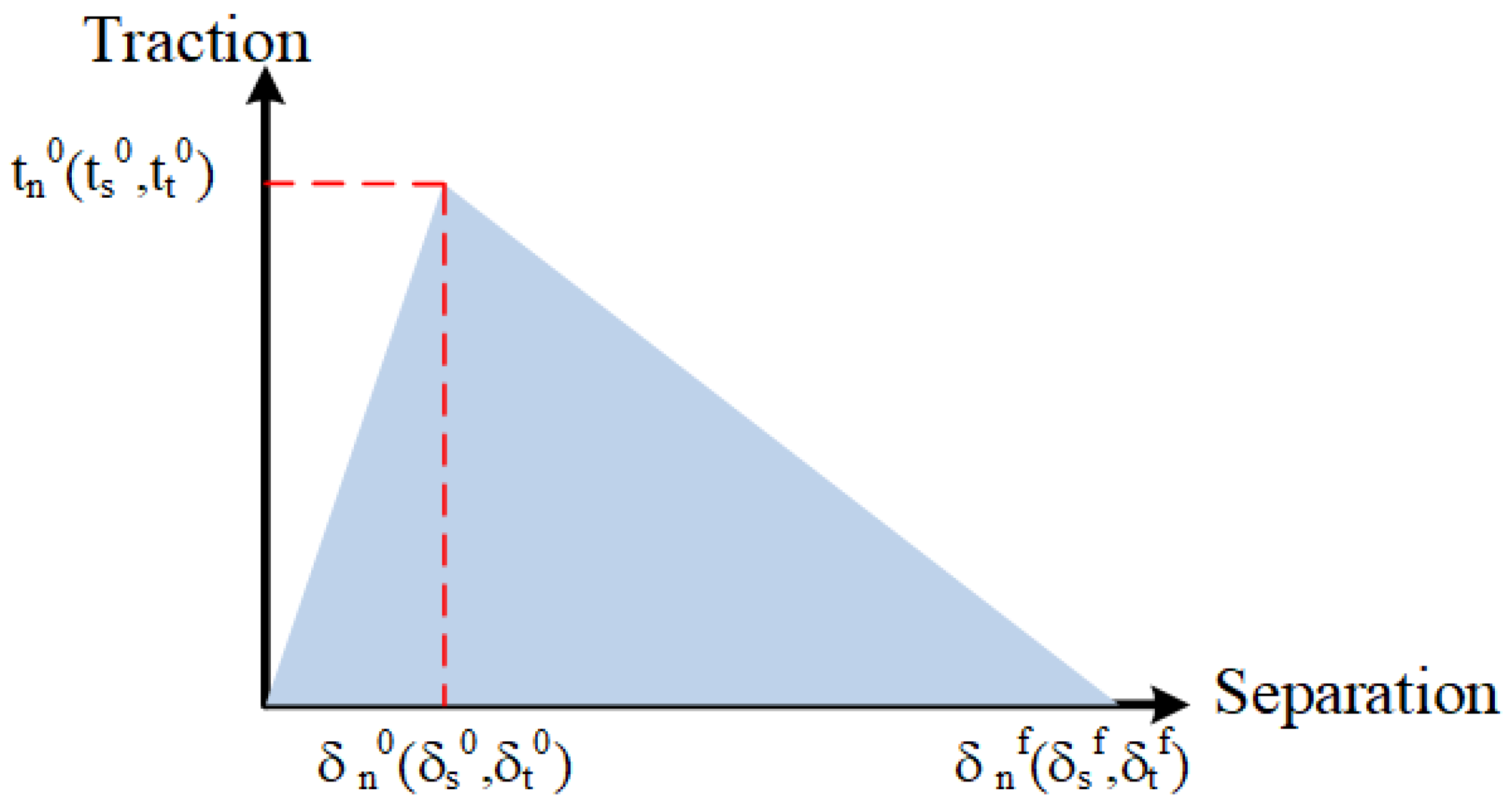
2.1. Cohesive Zone

Assuming that the cohesive element possesses a finite thickness and macroscopic characteristics [35], it can be described by the traction–separation law to depict cohesive behavior. Within ABAQUS, this is facilitated by postulating the element’s initial linear elastic behavior, followed by the onset and evolution of damage. During the explicit simulation process, the adhesive element exhibits time-dependent viscoelasticity, which can simulate rate-dependent behavior elasticity. The evolution of the elastic properties, both normal and in dual shear nominal values, can be represented by the following equation:
t n ( t ) = t 0   n ( t ) + 0 t k . R ( s ) t 0   n ( t s ) d s t s ( t ) = t 0   s ( t ) + 0 t g . R ( s ) t 0   s ( t s ) d s t t ( t ) = t 0   t ( t ) + 0 t g . R ( s ) t 0   s ( t s ) d s
where t0n(t), t0s(t), and t0t(t) are the instantaneous nominal traction of normal and two local shear directions at time t, respectively, and gR(t) and kR(t) represent the dimensionless shear modulus and normal modulus, respectively.
Assuming that the initial response of the cohesive element to external forces is linear, damage evolution occurs according to the conditions defined by the user once the criteria for damage initiation are met. Upon reaching the stress–strain conditions, damage commences. Figure 1 illustrates the failure mechanism typical of the classic traction–separation law response, where tn0, ts0, and tt0 represent the peak nominal stresses when deformation is entirely perpendicular to the interface or in the first or second shear directions, respectively. When stress reaches these values, the cohesive element begins to incur damage, with the corresponding stiffness degradation factor (SDEG) = 0. δn0, δs0, and δt0 denote the initial displacement at damage onset, which is completely perpendicular to the interface or purely in the direction of the first or second shear. Following the initial crack formation, the separation force monotonically decreases, indicating that the element is in a strain-softening state [33]. δnf, δsf, and δtf represent the displacements at the point of complete failure of the element, with the corresponding stiffness degradation factor (SDEG) = 1.
In ABAQUS 2023 software, whether the element is damaged is determined by the secondary nominal stress criterion. When the nominal stress ratio reaches one, the damage begins:
t n t 0   n 2 + t s t 0   s 2 + t t t 0   t 2 = 1
These parameters, which have been explained above, < > mean that cohesive elements do not suffer damage under pure shear and compression [36].
To describe the damage evolution of combined deformation behavior at the interface of normal and tangential directions, the concept of effective displacement is introduced:
δ m = δ n 2 + δ s   2 + δ t   2
A damage variable D is introduced to describe the damage within the material and capture the subsequent evolution process. A damage factor of 0 indicates no damage, whereas a value of 1 signifies complete damage. For linear softening, the damage variable D is a function of δm:
D = δ m   f ( δ m   max δ m   0 ) δ m   max ( δ m   f δ m   0 )
where δmmax is the maximum effective displacement during loading.
The interface stiffness k is expressed by the following equation:
k n = E T = 2 G δ n   0 δ n   f
where E is the stiffness of the bonding element, T is the thickness of the bonding element, and G is the energy consumed during the complete damage process of the element. Then, the normal stiffness kn and shear stiffness ks, kt can be expressed using the damage factor D:
k n = ( 1 D ) k n   0 k s = ( 1 D ) k s   0 k t = ( 1 D ) k t   0
In the equation, kn0, ks0, and kt0 represent the initial normal and shear stiffnesses of the adhesive element prior to reaching the tensile limit, respectively. Consequently, the normal force, shear force, and tangential force can be expressed as per the following equation:
t n = ( 1 D ) t n   0 , t n   0 0 t n   0 , t n   0 0 t s = ( 1 D ) t s   0 t t = ( 1 D ) t t   0

2.2. Mechanical Specific Energy

Mechanical-specific energy effectively quantifies the rock-breaking efficiency of cutting cutters of various shapes. It signifies the energy that is expended by a cutting cutter to fracture a unit volume of rock, with lower values denoting higher rock-breaking efficiency [37]. This concept can be mathematically represented as follows:
M S E = E V
where E represents the energy in the rock-breaking process of the tool, where the unit is mJ; V is the volume of broken rock, unit mm3; and MSE is the mechanical specific energy, unit mJ/mm3.
Regarding Equation (8), the energy E consumed in rock-breaking can be conceptualized as the product of the distance l traversed by the cutting cutter during the rock-breaking process and the average cutting force F encountered. The volume of the fractured rock can be approximated as the product of the contact area Xr between the cutter and the rock and the cutting distance l. Consequently, the formula for MSE can be reformulated as follows:
M S E = F l X r l = F X r
Figure 2 presents a schematic of the cutter–rock contact, where α represents the back rake angle, u denotes the cutting depth, and S signifies the length of contact between the cutter and the rock, representing the projected length of the cutting depth. By projecting the contact surface between the cutter and the rock, the projected contact area X with the rock is obtained, with O being the center of the cutter surface’s circle. Hence, the projected contact area between the cutter and the rock can be considered as the area of the sector OADC minus the area of the triangle OAC:
X = S O A D C S O A C
The angle of AOB θ can be calculated as follows:
θ = arccos ( R S R )
The relationship between the projected length of the contact between the cutter and the rock and the depth of the cut is as follows:
S = u cos α
Combined with Formulas (11) and (12), the projected contact area X between the cutter and the rock can be calculated as follows:
X = R 2 θ R sin θ ( R S ) = R 2 ( θ sin θ ) + S R sin θ
Based on the projected area X and the forward inclination angle α, the actual area Xr of the cutter in contact with the rock can be calculated as follows:
X r = R 2 ( θ sin θ ) + S R sin θ cos α
According to the calculated area formula and the cutting force, the mechanical specific energy under any parameters can be calculated to judge the rock-breaking efficiency of the cutter.

2.3. Establishment and Verification of Finite Element Model

PDC cutters are embedded in the drill bit blades. When the drill bit is subjected to WOB and torque, the cutter acquires a downward velocity v and an angular velocity ω around the center of the drill bit. To facilitate the observation of the cutter’s rock-breaking state during the simulation process, the rotary cutting motion of the cutter is considered to be an instantaneous state at a certain moment, allowing the cutter’s motion to be simplified to a linear motion at a fixed cutting depth, as illustrated by the red frame in Figure 3. Due to the significant computational demand for inserting cohesive elements into the finite element mesh model, a method of taking the thickness of the midsection of the three-dimensional model to establish the mesh model for rock breaking by the cutter was adopted [38]. This modeling approach not only accurately reflects the state of interaction between the cutter and the rock, as shown by the green frame in Figure 3, but also reduces the computational load [39]. The finite element model of the rock has a thickness of 0.5 mm, with the cutter set for a cutting depth of 1 mm, a diameter of 13.44 mm, a back rake angle of 15°, and the rock having a length of 80 mm, and a height of 30 mm. To simulate irregular rock chips, the rock is discretized using C3D6 elements, and the cutter uses C3D8R elements, with mesh refinement at the contact location to a size of 0.1 mm, while the rest is kept at default. The simulation method in this paper is to embed cohesive zone elements (CZEs) on the physical unit boundary of the global domain. The whole process of deformation and the fracture and failure of rock materials is simulated by the damage and failure of CZEs. In order to achieve this process, the initial finite element mesh needs to be processed; first, the solid elements are discretized, then the CZE nodes are sorted, and finally, the zero-thickness CZEs are generated. According to the CZE mathematical model in the paper, the crack is automatically generated. The model restricts the y-direction degrees of freedom perpendicular to the cutting direction, fully fixes the bottom surface, and restricts the x-direction degrees of freedom of the two sides parallel to the cutting direction. To investigate the acceleration mechanism of the cutter, conventional cutters (CC) and saddle-shaped cutters (SCs) were selected as objects of study.
During the simulation process, cutter wear was neglected, and the cutter was treated as a rigid body with a cutting speed of 1 m/s, a friction coefficient of 0.3, and a simulation time of 0.06 s. The chosen rock material was granite, with a density of 2650 kg/m3, Poisson’s ratio of 0.25, elastic modulus of 40 GPa, and compressive strength of 113 MPa. To ensure the accuracy of the granite parameters, uniaxial compression simulations were initially conducted. The granite had a diameter of 50 mm and a length of 100 mm, with rigid discs at both ends. The lower disc remained stationary while the upper disc applied a displacement of 5 mm downwards. The fracture process of rock materials is mainly controlled by the input parameters of CZEs, which consist of the following six mechanical parameters: type I/Ⅱ fracture energy, peak normal/tangential tractive force, and initial normal/tangential stiffness. After repeated debugging, it was found that when the CZE parameters shown in Table 1 were used, the simulation results were in good agreement with the experimental results. The simulation results were compared to experimental outcomes, as illustrated in Figure 4, which presents the crack comparison for both simulated and experimental granite [27]. From the figure, it is evident that the simulated and experimental crack patterns are similar. Hence, the constructed granite model is capable of reflecting the actual state.

3. Results and Discussion

3.1. Rock Breaking Mechanism

Figure 5a,b depict the cutting forces and MSE during the rock-breaking processes for CC and SC, respectively. As indicated by Figure 5a, under identical conditions, SC exhibits a smaller peak cutting force and less fluctuation, implying reduced resistance during the rock-breaking process. Calculations show that the average cutting force for SC is approximately 47.2% lower than that for CC. Figure 5b reveals that the energy consumed by SC in the rock-breaking process is significantly lower than that for CC, which is attributed to reduced rock-breaking resistance. It has been calculated that the MSE for SC is about 31.1% lower than that for CC, indicating a substantial increase in efficiency.
To ascertain whether the simulation process accurately captures the crack characteristics during the rock breaking by the cutter, the stress contour for the CC simulation of rock breaking is first recorded in Figure 6 and compared with the experimental results of Cheng et al. [40]. As illustrated in the figure, the simulation method employed in this study more accurately captures various crack patterns during the actual fracturing process of granite. Additionally, the simulation enables the observation of microcracks and the stress state of the rock, which are difficult to capture with high-speed cameras. The simulation also accurately captures the formation and movement of rock chips. Since the load step in the simulation is fixed at 0.3 ms, it results in a visual accumulation of rock chips, which, however, does not significantly impact the study of the rock-breaking mechanism of the cutter and can be disregarded. Hence, the methodology adopted in this study is reasonable.
Figure 7 records the stress contour of the rocks during the rock-breaking processes of CC and SC at the same moment. It is generally believed that microcracks develop beneath the broken area of the cutter. At the onset of rock breaking, the lower tip of the cutter fractures the rock, causing damage on impact, followed by the movement of some granular rock debris into the debris flow area due to the action of the cutter [41]. Additionally, due to the cutting action of the cutter, a main crack develops along the upper oblique end of the impact zone, producing blocky rock chips, which is a process that is critical to determining rock-breaking efficiency, as schematically shown in Figure 8. From Figure 7, it can be first observed that the stress distributions in the rocks differ markedly during the breaking processes of the two types of cutters, with SC exhibiting a more concentrated stress range, which is attributed to its ridge-like structure that more readily achieves the yield stress of the rock, undeniably enhancing the impact zone’s damage during rock breaking. Stress concentration can be determined directly and qualitatively by the rock stress contour without quantification. The stress concentration in a specific area is more conducive to the formation of tensile cracks and contributes to rock breaking. At the initial stage of rock breaking (column 1 in Figure 7), while CC did not produce clear main cracks after impacting the rock, SC already generated main cracks and large rock chips, mainly due to its arcuate structure altering the rock’s stress state, enhancing the tensile stress exerted on the rock during the cutter’s rock-breaking process, and thereby improving rock-breaking efficiency and reducing resistance (as rocks are more easily fractured under tensile stress [12]). This situation prevails not only at the initial stage of rock breaking but also in subsequent stages, as illustrated in columns 2 and 3 of Figure 7. Notably, while CC develops many microcracks on the underside post-fracturing, SC does not exhibit this pattern, indicating that SC’s structure aids in focusing the rock-breaking energy. Furthermore, the volume of rock chips produced by SC breaking the rock is significantly larger than that of CC, indicating higher efficiency and lower cutting forces during SC’s rock-breaking process.
Statistical analysis of the quantity and types of fractures to further examine the rock-breaking efficacy of cutters was carried out, as demonstrated in Figure 9a,b. Figure 9a reveals that, in comparison to SC, CC generated a greater number of fractures in rocks during operation. This phenomenon, as verified by Figure 7, occurred because the rock-breaking process with CC resulted in the formation of more micro-fractures beneath the tool, whereas SC facilitated the generation of principal fractures, thus enhancing rock-breaking efficiency. Figure 9b illustrates that the emergence of tensile fractures is not an initial occurrence, implying that shear fractures are the first to form when cracks develop in the rock. The proportion of tensile fractures generated during the rock-breaking process by SC is significantly higher than that of CC, indicating that the high efficiency and low cutting force of SC can be attributed to the generation of a higher proportion of tensile fractures. This also validates the accuracy of the aforementioned finite element analysis results. The arc and ridge structures of SC assist in the generation of principal and tensile fractures, thereby substantially improving rock-breaking efficiency and reducing rock-breaking resistance.

3.2. Different Confined Pressures and Hydrostatic Pressure

Deep rock formations are often subject to the dual effects of hydrostatic pressure and confining pressure and become more “dense” and, thus, more challenging to fracture with PDC cutters [42]. As illustrated on the left side of Figure 10, rocks under hydrostatic and confined pressures become significantly denser. To simulate the confined pressure and net hydrostatic pressure exerted on rocks, it was initially assumed that the pressure is uniformly distributed on the surface. This approach references the methodology detailed in the document for applying confined pressure in simulation models, wherein the area ratio is used to proportionally scale the applied confined and hydrostatic pressures [43]. At a cutting speed of 1 m/s and a cutting depth of 1 mm, the rock-breaking process by the tool under various confined and hydrostatic pressures (namely 5 MPa, 10 MPa, 15 MPa, and 20 MPa) was investigated. The model established, as shown on the right side of Figure 10, featured the rock’s upper surface, subjected to net hydrostatic pressure, the left and right surfaces under confined pressure, and the lower fixed surface. Constraints were applied to the surface perpendicular to the Z-direction to limit its freedom in the Z-direction.
Figure 11a,b present the mean cutting forces and MSE for two types of cutters under varying confined pressures, respectively, and the error line in Figure 11a refers to the standard deviation of the mean cutting force and the value of cutting forces at each moment. As depicted in Figure 11a, under the same conditions, with the increase in hydrostatic and confined pressures, the cutting forces for both types of cutters increase, indicating that the rock becomes more difficult to fracture. It is also observed that with the increase in pressure, the fluctuation in cutting force becomes clearer, elevating the risk of cutter failure. However, the average cutting force for SC remains consistently lower than that for CC, with less fluctuation in the force.
Figure 11b illustrates that with rising pressures, the MSE for both types of cutters increases, suggesting a decrease in efficiency for both. Nonetheless, SC’s rock-breaking efficiency consistently surpasses that of CC, with the difference in efficiency between the two being most significant at a hydrostatic and confined pressure of 10 MPa. Beyond 10 MPa, the efficiency gap between the two narrows, yet SC’s MSE remains over 15% lower than that of CC. Therefore, SC demonstrates a more considerable efficiency in deep rock-breaking compared to CC, significantly aiding in a reduction in drilling costs.
To investigate the reasons behind the observed phenomena, Figure 12 captures the stress contour of rocks post-fracture by the two types of cutters under various confined pressures. The figure demonstrates that with an increase in confined pressure, more fractures perpendicular to the cutting direction are generated during the rock-breaking process, and the area of the rock’s stress zone gradually enlarges. This indicates that the presence of confined and hydrostatic pressures leads to greater consumption of energy perpendicular to the cutting direction during rock fracturing. Additionally, it can be observed that the existence of hydrostatic pressure complicates the formation of rock debris, leading to accumulation in the cutting area, which is consistent with the findings of Xiong et al. [19]. Essentially, the presence of confined and hydrostatic pressures inhibits the formation of principal fractures during the cutting process, favoring the generation of micro-fractures and thereby reducing the efficiency of rock fracturing. However, under conditions of confined and hydrostatic pressure, SC generates fewer micro-fractures with shorter lengths compared to CC, resulting in higher rock-breaking efficiency.
To elucidate the reasons behind the high efficiency of SC under confined pressure conditions in deep rock formations, the total number of fractures and the proportion of tensile fractures generated by the two types of cutters under different confined pressures were recorded, as illustrated in Figure 13. Figure 13a reveals that, with the increase in hydrostatic and confined pressures, the total number of fractures in rocks post-fracturing by both cutters rises. This phenomenon, as inferred from Figure 12, is attributed to an increase in the number of micro-fractures, specifically those perpendicular to the cutting direction of the cutter, following rock fragmentation. However, the total number of fractures generated by SC remains consistently lower than CC. Figure 13b indicates that the increase in hydrostatic and confined pressures inhibits the formation of tensile fractures during the rock-breaking process, resulting in a reduced proportion of tensile fractures for both types of cutters. Additionally, the proportion of tensile fractures in rock fracturing by SC consistently exceeds that of CC, underscoring SC’s higher efficiency in deep rock formations when fracturing under confined pressure conditions.
In summary, the increase in confined and hydrostatic pressures inhibits the formation of tensile fractures during the rock-breaking process, making rock debris more difficult to generate and remove while also promoting the formation of micro-fractures, consuming energy in the rock-breaking process and also reducing rock-breaking efficiency. However, the unique ridge-like structure of the SC cutter aids in focusing rock-breaking energy, allowing it to maintain the formation of a rock-breaking impact zone even under high hydrostatic and confined pressures and preventing the generation of additional micro-fractures. Simultaneously, the arc-like structure of SC facilitates the creation of tensile fractures, aiding in rock debris formation and thereby enhancing rock-breaking efficiency.

3.3. Different Back Rake Angles

Under identical conditions, the back rake angle essentially determines the contact area between the PDC cutter and the rock, thereby influencing the rock-breaking efficiency of the cutter [44]. Hence, simulations were conducted to evaluate the rock-breaking scenarios for CC and SC at various back rake angles (10°, 15°, 20°, 25°, 30°) under the conditions of a confined pressure and hydrostatic pressure of 20 MPa, a cutting speed of 1 m/s, and a cutting depth of 1 mm.
Figure 14 documents the mean cutting forces and MSE for two types of cutters at varying back rake angles; the error line in Figure 14a refers to the standard deviation of the mean cutting forces value and the cutting forces value at each moment. As depicted in Figure 14a, an increasing trend in cutting forces is generally observed for both cutter types with the escalation of the back rake angle. However, within the simulation range, the SC exhibits less fluctuation in cutting forces (indicated by shorter error bar lengths), with the mean values of cutting forces for SC changing insignificantly across different back rake angles. As demonstrated in Figure 14b, at a back rake angle of 10°, the efficiency of SC is lower than that of CC. When the back rake angle exceeds 10°, the efficiency of SC consistently surpasses that of CC. Within the simulated range, the MSE of SC initially decreases and then increases, reaching its minimum at a back rake angle of 15°. Essentially, the back rake angle dictates the aggressiveness of the rock-breaking process during cutting; a larger angle implies greater aggressiveness. However, an excessively large back rake angle can hinder the timely evacuation of cuttings, which is detrimental to rock breaking [22]. The relatively stable variation in cutting forces and MSE for SC across different back rake angles suggests a wide applicability of its back rake angle. When breaking hard rock, a larger back rake angle can be selected to enhance the rock’s aggressiveness and prevent the occurrence of stick–slip vibrations [12].
Figure 15 captures the variations in the number of rock-breaking cracks and the proportion of tensile cracks for two types of cutters across different back rake angles. From Figure 15a, it is evident that at a back rake angle of 10°, the total number of cracks generated by SC during rock breaking exceeds that of CC. When the back rake angle is greater than 10°, the number of cracks produced by CC during rock breaking surpasses that of SC. Figure 15b reveals that at a back rake angle of 10°, the proportion of tensile cracks generated by SC in rock breaking is lower than that of CC. However, once the back rake angle exceeds 10°, the proportion of tensile cracks in rock breaking by SC becomes greater than that of CC.
Hence, it can be discerned that the number of cracks generated and the proportion of tensile cracks during the rock-breaking process are directly related to the cutting force and rock-breaking efficiency. Under identical conditions, a higher total number of cracks and a lower proportion of tensile cracks generated during rock breaking correlate with lower rock-breaking efficiency, and vice versa. CC, compared to SC, produces more microcracks during rock breaking, consuming more energy. Conversely, the unique ridge and arc structures of SC aid in the formation of tensile cracks and the generation of cuttings, thereby enhancing its efficiency. Based on the variations in MSE and cutting forces across different back rake angles for SC, the recommended range of back rake angles for use under high confined and hydrostatic pressure conditions is 15° to 20°.

3.4. Influence of Different Arc Radii on SC Rock Breaking

The results from Section 3.2 and Section 3.3 in this paper collectively indicate that the arc structure of SC plays a facilitative role in the generation of tensile cracks and primary cracks during the rock-breaking process. Thus, it is essential to understand the impact of the arc structure parameters of SC on crack formation in rock breaking. The schematic of the SC arc structure parameters, as illustrated in Figure 16, suggests that these parameters may significantly influence the formation of primary cracks during the rock-breaking process, affecting the volume of rock chips and thereby determining the efficiency of rock breaking. Given this, simulations were conducted for SC’s rock-breaking process at different arc radii (20 mm, 30 mm, 40 mm, 50 mm, 60 mm) under the conditions of the confined pressure and hydrostatic pressure of 20 MPa, a cutting speed of 1 m/s, and a cutting depth of 1 mm.
Figure 17 presents the average mechanical specific energy (MSE) and cutting forces of SC during rock breaking at different arc radii. The average cutting force error in Figure 17 is quite significant, but the level of the error is acceptable when compared to other results. The graph indicates that with an increase in the arc radius, the cutting force of SC initially increases and then decreases, while the MSE first rises and then falls, implying that the rock-breaking efficiency of SC initially declines before improving. Figure 18 shows the total number of cracks and the proportion of tensile cracks in SC’s rock breaking at various arc radii, revealing that with the increase in arc radius, the total number of rock-breaking cracks initially increases and then decreases, whereas the proportion of tensile cracks first decreases and then increases. From Figure 17 and Figure 18, it can be inferred that changes in the arc radius affect the total number of cracks and the proportion of tensile cracks generated during SC’s rock-breaking process, thereby influencing the cutting force and MSE (rock-breaking efficiency). Within the simulated range, an arc radius of 20 mm results in the lowest number of cracks and the highest proportion of tensile cracks, thus leading to the highest rock-breaking efficiency and the lowest cutting force.
Figure 19 depicts the stress contour for SC rock breaking at various arc radii. It is distinctly observable from the figure that an increase in the arc radius leads to a rise in the number of longitudinal cracks during SC rock breaking, dispersing rock-breaking energy and thereby reducing the efficiency of rock breaking. This observation matches with the analytical conclusions drawn in Section 3.2. However, beyond a certain increase in the arc radius, for instance, at 50 mm, there was an increase observed in the proportion of tensile cracks and a reduction in the total number of cracks, at which point the rock-breaking efficiency of SC even surpassed that observed at arc radii of 30 mm and 40 mm. Comparing the scenarios with arc radii of 30 mm and 50 mm, it was found that at an arc radius of 30 mm, the rock chips produced clung to and were expelled along the arc surface of SC. At an arc radius of 50 mm, there was a tendency for the rock chips produced during SC rock breaking to move in the cutting direction, suggesting that in this case, SC’s structure is conducive to the ejection of rock chips, avoiding the re-cutting of the chips and thus reducing energy consumption. According to Figure 18, an arc radius of 50 mm is more favorable for the formation of tensile cracks in rocks than an arc radius of 30 mm, thereby offering higher efficiency. Moreover, an arc radius of 20 mm is more conducive to the generation of tensile cracks, but it might lead to the accumulation of rock chips within the arc, and a smaller arc radius might result in a thinner polycrystalline diamond layer, which is not favorable for the longevity of the SC cutter. However, this can be mitigated by optimizing the arc structure to an arc–straight–arc configuration that, while facilitating chip removal, also ensures the longevity of the SC. The findings in this section can provide a direction for the subsequent optimization of SC.

4. Conclusions

This study employs finite element and cohesive zone methods to simulate and compare the crack behavior in rocks during the rock-breaking process using saddle-shaped and conventional PDC cutters, further elucidating the rock-breaking mechanism of saddle-shaped cutters from the perspectives of crack quantity and the proportion of tensile cracks. It then considers the influence of confined pressure on the rock cracks during the cutter’s rock-breaking process, explaining the relationship between rock-breaking efficiency and cracks under different confined pressures. Moreover, this study analyzes the impact patterns of different back rake angles on cutter rock-breaking cracks under the same confined pressure and explores the influence of different arc radii on the saddle-shaped cutter’s rock-breaking cracks under the same confined pressure, proposing directions for optimization. Finally, this study conducts rock-breaking simulations using full-size drill bits equipped with saddle-shaped cutters of various arc radii and optimized saddle-shaped cutters, comparing them with drill bits and utilizing conventional cutters to understand the full-size drill bit’s rock-breaking mechanism and effectiveness. It should also be mentioned that geothermal drilling often involves high-temperature environments. However, the model does not consider the effect of high temperature because CZEs do not support this function for the time being, and it is necessary to discuss how high temperature affects the performance of saddle PDC cutters in other specific ways. The following conclusions were drawn:
(1)
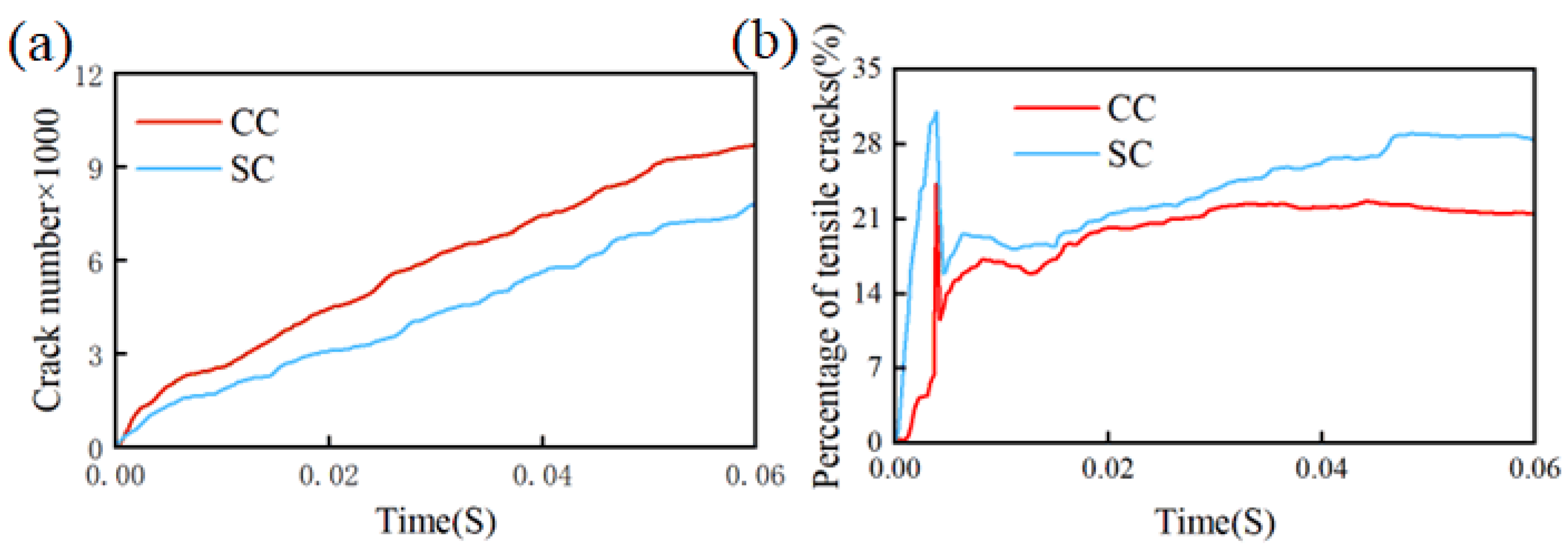
Compared to conventional PDC cutters, the ridge-like structure of saddle-shaped cutters more effectively concentrates rock-breaking stresses, facilitating the initiation of cracks in the rock. Simultaneously, the arcuate structure of saddle-shaped cutters favors the generation of tensile cracks in the rock, thereby making the generation of rock chips during the rock-breaking process more likely. Consequently, the total number of rock cracks produced during the rock-breaking process with saddle-shaped cutters is lower than that of conventional PDC cutters, and the proportion of tensile cracks is higher. This represents the key to the high efficiency of rock breaking achieved with saddle-shaped cutters.
(2)
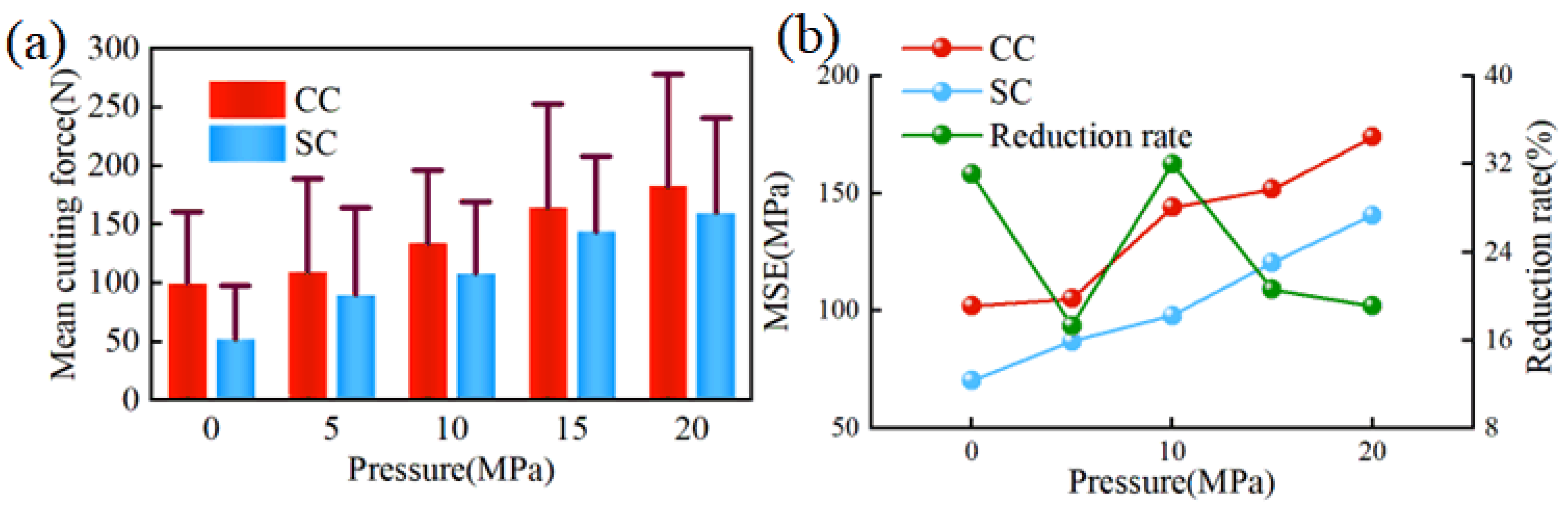
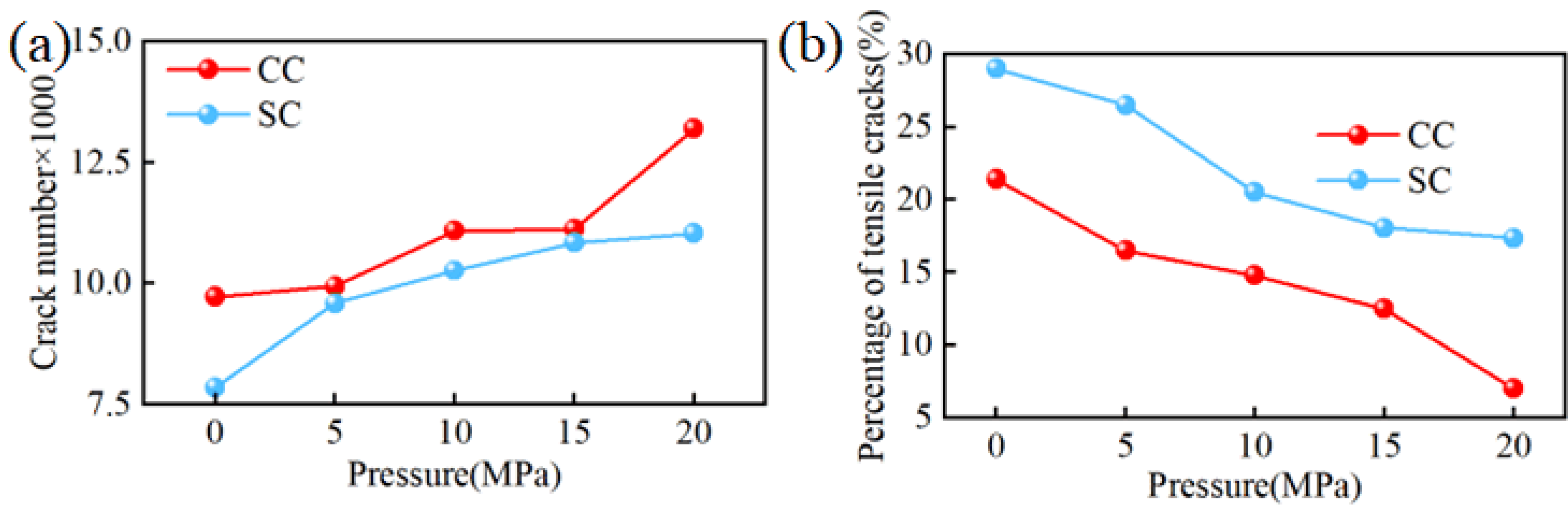
The increase in confined pressure inhibits the generation of tensile cracks during the rock-breaking process with PDC cutters while simultaneously promoting the formation of more microcracks, dispersing rock-breaking energy and reducing the cutter’s rock-breaking efficiency. However, in comparison, the ridge-like and arcuate structures of saddle-shaped PDC cutters ensure a higher proportion of tensile cracks in rocks under high confined pressure, helping to suppress the formation of microcracks. Therefore, saddle-shaped PDC cutters are more suitable for drilling in deep hard formations.
(3)
Under constant conditions, as the back rake angle of saddle-shaped cutters increases, the total number of rock-breaking cracks first decreases and then increases, whereas the proportion of tensile cracks exhibits an inverse trend. Based on this observation, it is recommended to utilize a back rake angle range of 15° to 20° for saddle-shaped cutters in deep, hard formations.
(4)
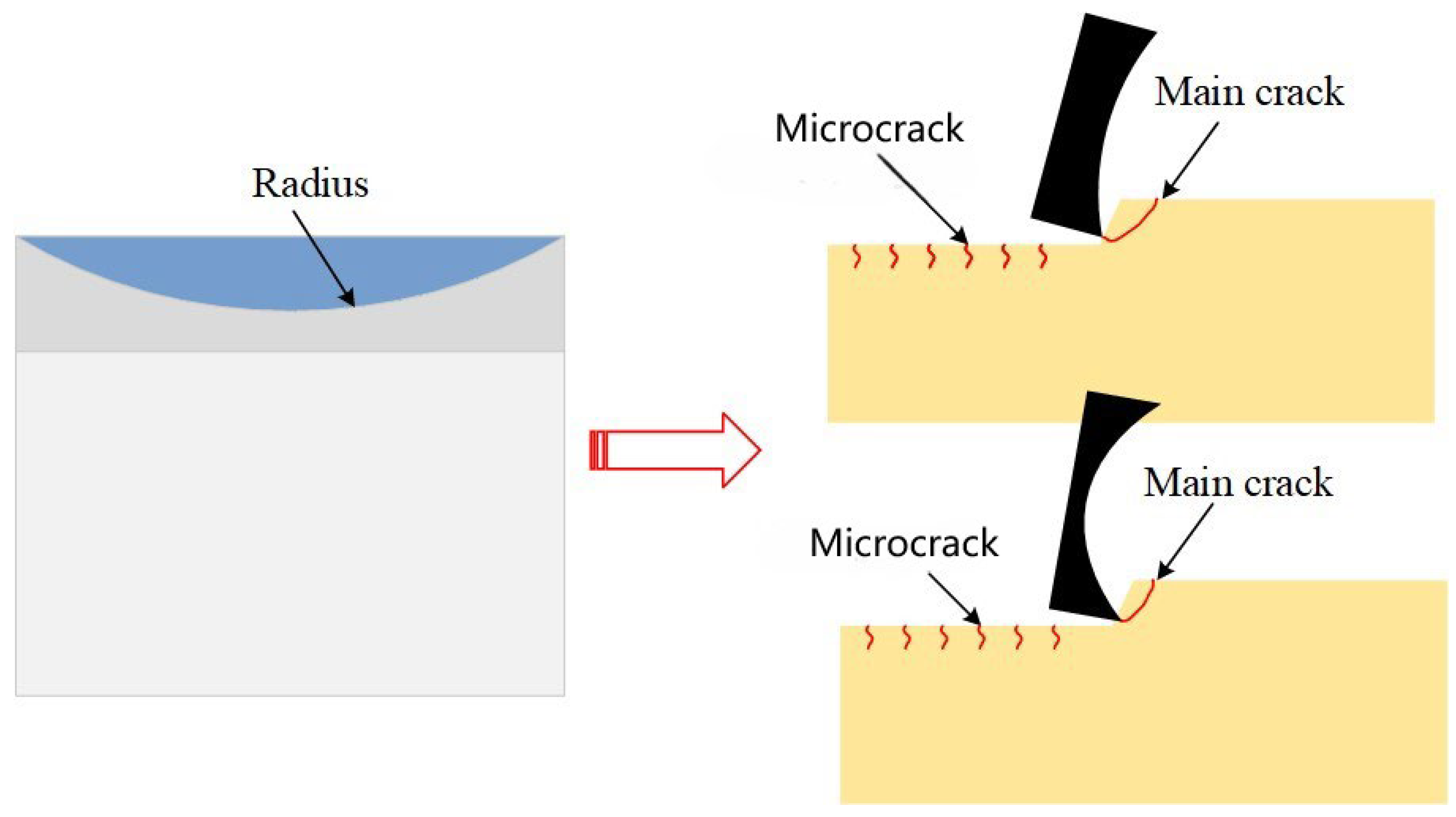
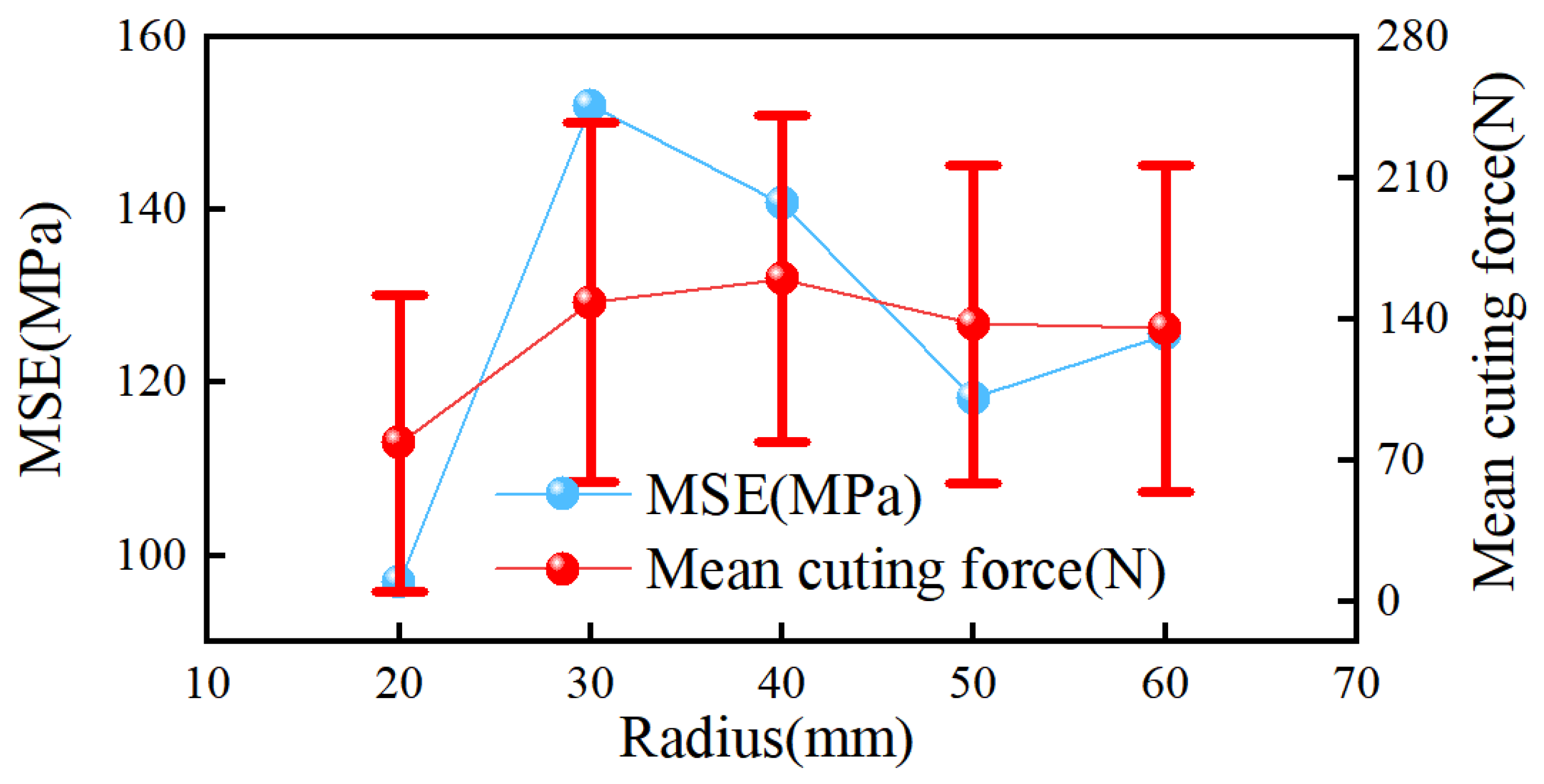
The arc radius significantly impacts the generation of rock-breaking cracks by saddle-shaped cutters. When the arc radius is 20 mm, saddle-shaped cutters produce the most tensile cracks and achieve the highest rock-breaking efficiency. However, with this size, the arc tip is relatively weak, potentially affecting the fatigue life. Therefore, an arc radius between 50 mm and 60 mm is recommended. Additionally, this analysis suggests an optimization direction for saddle-shaped cutters with an arc radius of 20 mm: modifying the shape from an arc to an arc–straight–arc configuration to enhance the strength at the weak arc position.

Author Contributions

Conceptualization, R.Y. and Z.W.; methodology, Y.C.; software, R.Y.; validation, Z.W. and Y.C.; formal analysis, R.Y.; investigation, Y.C.; resources, Z.W.; data curation, Y.C.; writing—original draft preparation, R.Y. and Y.C.; writing—review and editing, Z.W.; visualization, Y.C.; supervision, Z.W.; project administration, R.Y.; funding acquisition, Z.W. All authors have read and agreed to the published version of the manuscript.

Funding

This research was funded by the Hundred-Talent Program (Grant No. Z16178/290088247), Xi’an Shiyou University for publication funding, and Shanxi Provincial Key Project-International Collaboration Project of Science and Technology (Grant No. 2022KW-10/221822021).

Data Availability Statement

Data will be made available upon request.

Conflicts of Interest

The authors declare that they have no known competing financial interests or personal relationships that could have appeared to influence the work reported in this paper. The authors have full access to all data in this study.

References

  1. Cai, M.; Tan, L.; Tan, B.; Luo, X.; Zeng, J.; Mao, D.; Lin, Q. Experimental and numerical study on the dynamic characteristics of full-size PDC bit. Mech. Syst. Signal Process. 2023, 200, 110560. [Google Scholar] [CrossRef]
  2. Zuo, W.; Shi, F.; Manlapig, E. Electrical breakdown channel locality in high voltage pulse breakage. Miner. Eng. 2012, 69, 196–204. [Google Scholar] [CrossRef]
  3. Lund, J.W.; Toth, A. Direct Utilization of Geothermal Energy 2020 Worldwide Review. Geothermics 2021, 90, 101915. [Google Scholar] [CrossRef]
  4. Guzek, A.; Shufrin, I.; Pasternak, E.; Dyskin, A.V. Influence of drilling mud rheology on the reduction of vertical vibrations in deep rotary drilling. J. Pet. Sci. Eng. 2015, 135, 375–383. [Google Scholar] [CrossRef]
  5. Wu, Z.; Yuan, R.; Zhang, W.; Hu, S.; Jiang, W. Numerical Simulation and Field Test of a PDC Bit with Mixed Cutter Arrangement to Break Non-Homogeneous Granite. Appl. Sci. 2023, 13, 9133. [Google Scholar] [CrossRef]
  6. Liu, J.; Zheng, H.; Kuang, Y.; Xie, H.; Qin, C. 3D Numerical Simulation of Rock Cutting of an Innovative Non-Planar Face PDC Cutter and Experimental Verification. Appl. Sci. 2019, 9, 4372. [Google Scholar] [CrossRef]
  7. Fu, X.; Huang, Z.; Shi, H.; Song, H.; Wu, H. Comparison of fracture characteristics of different PDC cutters penetrating carbonate rock. Geoenergy Sci. Eng. 2023, 223, 211536. [Google Scholar] [CrossRef]
  8. Shao, F.; Liu, W.; Gao, D.; Ye, Y. Study on rock-breaking mechanism of axe-shaped PDC cutter. J. Pet. Sci. Eng. 2021, 205, 108922. [Google Scholar] [CrossRef]
  9. Shao, F.; Liu, W.; Gao, D.; Zhao, X. Development and Verification of Triple-Ridge-Shaped Cutter for PDC Bits. SPE J. 2022, 27, 3849–3863. [Google Scholar] [CrossRef]
  10. Zeng, Y.; He, W.; Zhang, Z.; Shi, H.; Zhou, J.; Ding, S.; Ma, G. Rock-breaking performances of innovative triangular-shaped polycrystalline diamond compact cutter. Rev. Sci. Instrum. 2021, 92, 035115. [Google Scholar] [CrossRef] [PubMed]
  11. He, W.; Zhang, R.; Liu, L.; Chen, Z.; Shi, H.; Huang, Z.; Xiong, C.; Li, X.; Sun, J.; Hu, C. Numerical simulation of rock-breaking mechanisms by triple-ridged PDC cutter in hard rocks. Geoenergy Sci. Eng. 2023, 229, 212148. [Google Scholar] [CrossRef]
  12. Wu, Z.; Yuan, R.; Zhang, W.; Liu, J.; Hu, S. Structure Design of Bionic PDC Cutter and the Characteristics of Rock Breaking Processes. Processes 2023, 12, 66. [Google Scholar] [CrossRef]
  13. Zhu, X.; Luo, Y.; Liu, W.; Yang, F.; Li, Z.; Lu, D. Rock cutting mechanism of special-shaped PDC cutter in heterogeneous granite formation. J. Pet. Sci. Eng. 2022, 210, 110020. [Google Scholar] [CrossRef]
  14. Xiong, C.; Huang, Z.; Yang, R.; Sheng, M.; Shi, H.; Dai, X.; Wu, X.; Zhang, S. Comparative analysis cutting characteristics of stinger PDC cutter and conventional PDC cutter. J. Pet. Sci. Eng. 2020, 189, 106792. [Google Scholar] [CrossRef]
  15. Chen, P.; Meng, M.; Miska, S.; Yu, M.; Ozbayoglu, E.; Takach, N. Study on integrated effect of PDC double cutters. J. Pet. Sci. Eng. 2019, 178, 1128–1142. [Google Scholar] [CrossRef]
  16. Li, S.; Zhu, X.; Liang, K.; Deng, Y.; Liu, H. Numerical simulation study on optimizing the conical cutter bit to break deep strata. Recent Pat. Eng. 2024, 18, e110523216781. [Google Scholar] [CrossRef]
  17. Peng, Q.; Zhou, Y.; Yu, J.; Yang, X.; Liu, Y.; Ma, C.; Cheng, C.; Ke, X. Study on rock breaking efficiency of special shaped cutters. IOP Conf. Ser. Earth Environ. Sci. 2022, 983, 012089. [Google Scholar] [CrossRef]
  18. Xiong, C.; Huang, Z.; Shi, H.; Chen, H.; Chen, Z.; He, W.; Zhang, B. Investigations on the Stinger PDC cutter breaking granitoid under in-situ stress and hydrostatic pressure conditions. Int. J. Rock Mech. Min. Sci. 2023, 164, 105312. [Google Scholar] [CrossRef]
  19. Xiong, C.; Huang, Z.-W.; Shi, H.-Z.; Yang, R.-Y.; Wu, G.; Chen, H.; He, W.-H. Performances of a Stinger PDC cutter breaking granite: Cutting force and mechanical specific energy in single cutter tests. Pet. Sci. 2023, 20, 1087–1103. [Google Scholar] [CrossRef]
  20. Liu, W.; Meng, X.; Weng, X.; Shen, X.; Zhu, X. Rock-breaking performance of specially-shaped PDC cutters from a new insight into the damage beneath cutting groove. Geoenergy Sci. Eng. 2023, 231, 212326. [Google Scholar] [CrossRef]
  21. Zhu, X.; Li, R.; Liu, W.; He, C. Analysis of Rock-Breaking Mechanism and Drillstring Dynamics of an Innovative Multi-Ridge-Curve-Shaped PDC Cutter. Arab. J. Sci. Eng. 2023, 48, 16587–16606. [Google Scholar] [CrossRef]
  22. Liu, W.; Deng, H.; Liu, Y.; Chen, X.; He, C.; Zhu, X. Experimental investigation of the rock cutting process with blunt PDC cutters. Geoenergy Sci. Eng. 2023, 226, 211803. [Google Scholar] [CrossRef]
  23. Liu, W.; Deng, K.; Yang, F.; Luo, Y.; Zhu, X. An experimental and numerical investigation on rock cutting behavior of specially-shaped PDC cutter. J. Mech. Sci. Technol. 2024, 38, 285–298. [Google Scholar] [CrossRef]
  24. Wei, J.; Liu, W.; Gao, D.; Guo, D. Effect of Polishing on Cutting Efficiency and Mechanical Properties of PDC Cutters. SPE J. 2024, 29, 700–713. [Google Scholar] [CrossRef]
  25. Xi, Y.; Wang, H.-Y.; Zha, C.-Q.; Li, J.; Liu, G.-H.; Guo, B.-Y. Numerical simulation of rock-breaking and influence laws of dynamic load parameters during axial-torsional coupled impact drilling with a single PDC cutter. Pet. Sci. 2023, 20, 1806–1827. [Google Scholar] [CrossRef]
  26. Ke, X.; Sun, J.; Yang, X.; Ma, C.; Yu, J.; Huang, K. Cutting mechanism of a special 3D concave-shaped PDC cutter applicable to the Weiyuan shale. J. Pet. Explor. Prod. Technol. 2023, 13, 1435–1451. [Google Scholar] [CrossRef]
  27. Zhang, Z.; Zhao, D.; Zhao, Y.; Gao, K.; Zhang, C.; Lü, X. 3D numerical simulation study of rock breaking of the wavy PDC cutter and field verification. J. Pet. Sci. Eng. 2021, 203, 108578. [Google Scholar] [CrossRef]
  28. Zhang, Z.; Zhao, D.; Zhao, Y.; Zhou, Y.; Tang, Q.; Han, J. Simulation and experimental study on temperature and stress field of full-sized PDC bits in rock breaking process. J. Pet. Sci. Eng. 2020, 186, 106679. [Google Scholar] [CrossRef]
  29. Yao, J.; Liu, B.; Zhu, H. Discrete Element Study on Rock Failure Mechanism by Shaped PDC Cutter Under Formation Conditions with In-Situ Stress and Temperature. In Proceedings of the ARMA/DGS/SEG International Geomechanics Symposium, Abu Dhabi, United Arab Emirates, 7–10 November 2022. [Google Scholar] [CrossRef]
  30. Zhu, X.; Luo, Y.; Liu, W.; He, L.; Gao, R.; Jia, Y. On the Mechanism of High-Voltage Pulsed Fragmentation from Electrical Breakdown Process. Rock Mech. Rock Eng. 2021, 54, 4593–4616. [Google Scholar] [CrossRef]
  31. Labra, C.; Rojek, J.; Oñate, E. Discrete/Finite Element Modelling of Rock Cutting with a TBM Disc Cutter. Rock Mech. Rock Eng. 2017, 50, 621–638. [Google Scholar] [CrossRef]
  32. Liu, X.; Zou, D.; Chen, Y.; Huang, Y.; Wang, Q. Analysis of PDC cutter cutting-broken conglomerate based on the discrete element method. Energy Sci. Eng. 2022, 10, 3580–3591. [Google Scholar] [CrossRef]
  33. Jiang, H.; Meng, D. 3D numerical modelling of rock fracture with a hybrid finite and cohesive element method. Eng. Fract. Mech. 2018, 199, 280–293. [Google Scholar] [CrossRef]
  34. Wang, H.; Liao, H.; He, Y.; Niu, W.; Wei, J.; Niu, J.; Gao, F. Experimental and numerical simulation study on the effect of granite grooving characteristics on PDC cutter cutting performance. Geoenergy Sci. Eng. 2023, 230, 212256. [Google Scholar] [CrossRef]
  35. Su, X.T.; Yang, Z.J.; Liu, G.H. Monte Carlo simulation of complex cohesive fracture in random heterogeneous quasi-brittle materials: A 3D study. Int. J. Solids Struct. 2010, 47, 2336–2345. [Google Scholar] [CrossRef]
  36. Zhao, Y.; Zhang, C.; Zhang, Z.; Gao, K.; Li, J.; Xie, X. The rock breaking mechanism analysis of axial ultra-high frequency vibration assisted drilling by single PDC cutter. J. Pet. Sci. Eng. 2021, 205, 108859. [Google Scholar] [CrossRef]
  37. Jaime, M.C.; Zhou, Y.; Lin, J.-S.; Gamwo, I.K. Finite element modeling of rock cutting and its fragmentation process. Int. J. Rock Mech. Min. Sci. 2015, 80, 137–146. [Google Scholar] [CrossRef]
  38. Xie, Y.; Wu, X.; Hou, Z.; Li, Z.; Luo, J.; Lüddeke, C.T.; Huang, L.; Wu, L.; Liao, J. Gleaning insights from German energy transition and large-scale underground energy storage for China’s carbon neutrality. Int. J. Min. Sci. Technol. 2023, 33, 529–553. [Google Scholar] [CrossRef]
  39. Zeng, Y.; Liu, W.; Ding, S.; Zhu, X. Numerical simulation analysis of hybrid impact cutting and its comparison with torsional impact cutting. J. Vibroeng. 2020, 22, 451–464. [Google Scholar] [CrossRef]
  40. Cheng, Z.; Sheng, M.; Li, G.; Huang, Z.; Shi, H.; Dai, X.; Guo, Z. Cracks imaging in linear cutting tests with a PDC cutter: Characteristics and development sequence of cracks in the rock. J. Pet. Sci. Eng. 2019, 179, 1151–1158. [Google Scholar] [CrossRef]
  41. Wei, J.; Liu, W.; Gao, D. Mechanism Analysis and Mathematical Modeling of Brittle Failure in Rock Cutting with a Single Sharp Cylinder-Shaped PDC Cutter. SPE J. 2023, 29, 651–669. [Google Scholar] [CrossRef]
  42. Li, W.; Ling, X.; Pu, H. Development of a Cutting Force Model for a Single PDC Cutter Based on the Rock Stress State. Rock Mech. Rock Eng. 2020, 53, 185–200. [Google Scholar] [CrossRef]
  43. Yao, Y. Linear Elastic and Cohesive Fracture Analysis to Model Hydraulic Fracture in Brittle and Ductile Rocks. Rock Mech. Rock Eng. 2012, 45, 375–387. [Google Scholar] [CrossRef]
  44. Yang, F.; Liu, W.; Zhu, X.; Xiang, C. The Rock-Breaking Mechanism of Thermal Spalling-Assisted Rock Cutting by PDC Cutter. Rock Mech. Rock Mech. Rock Eng. 2024, 57, 993–1012. [Google Scholar] [CrossRef]
Figure 1. Failure mechanism of separation–traction law.
Processes 12 01450 g001
Figure 2. The cutter is in contact with the rock.
Processes 12 01450 g002
Figure 3. The simplification of the model and the establishment of the finite element model.
Processes 12 01450 g003
Figure 4. Simulation and experiment of rock compression.
Processes 12 01450 g004
Figure 5. Cutting force and MSE: (a) Cutting force of the two cutters; (b) MSE for rock breaking with two cutters.
Processes 12 01450 g005
Figure 6. Comparison between simulated crack and experiment.
Processes 12 01450 g006
Figure 7. The stress contour of rock breakage by CC and SC at the same time.
Processes 12 01450 g007
Figure 8. The schematic of rock breaking by a cutter.
Processes 12 01450 g008
Figure 9. The number and proportion of cracks: (a) the number of cracks in the rock-breaking process of the two cutters; (b) the proportion of tensile cracks in the rock breaking process of the two cutters.
Processes 12 01450 g009
Figure 10. Modeling of hydrostatic pressure and confined pressure.
Processes 12 01450 g010
Figure 11. Cutting force and MSE of the two cutters under different confined pressures: (a) cutting force; (b) MSE.
Processes 12 01450 g011
Figure 12. The rock stress contour of rock breaking by two kinds of cutters under different confined pressures.
Processes 12 01450 g012
Figure 13. Total cracks and proportion of tensile cracks for the cutter under different confining pressures: (a) total cracks; (b) proportion of tensile cracks.
Processes 12 01450 g013
Figure 14. Cutting force and MSE of the cutter under different confining pressures: (a) cutting force of the two cutters; (b) MSE of both cutters.
Processes 12 01450 g014
Figure 15. Total number and proportion of rock cracks under different back angles of two kinds of cutting cutters: (a) total number of cracks; (b) proportion of tensile cracks.
Processes 12 01450 g015
Figure 16. Schematic diagram of arc radius of saddle cutter and rock breaking.
Processes 12 01450 g016
Figure 17. MSE and cutting force mean values of different arc radii SCs.
Processes 12 01450 g017
Figure 18. Total number and proportion of rock-breaking cracks of SC with different arc radii.
Processes 12 01450 g018
Figure 19. Stress contour of rock breaking by SC with different arc radii.
Processes 12 01450 g019
Table 1. CZEs parameters of finite element model.
CZEs Material ParameterNumerical Value
Initial normal stiffness k n /(MPa·mm−1)80,000
Peak normal tractive force t n 0 /MPa14.70
Type I fracture energy G I c /(N·mm−1)0.230
Initial tangential stiffness k s /(MPa·mm−1)40,000
Peak   tan gential   tractive   force   t s 0 /MPa45.20
Type II fracture energy G I I c /(N·mm−1)0.426
Disclaimer/Publisher’s Note: The statements, opinions and data contained in all publications are solely those of the individual author(s) and contributor(s) and not of MDPI and/or the editor(s). MDPI and/or the editor(s) disclaim responsibility for any injury to people or property resulting from any ideas, methods, instructions or products referred to in the content.

