Article

Integration of Chemical Looping Combustion to a Gasified Stream with Low Hydrogen Content

by
Guadalupe S. Fraga-Cruz
1,
Mario A. Pérez-Méndez
1,
Gladys Jiménez-García
2,
Rafael Huirache-Acuña
1,
Fabricio Nápoles-Rivera
1,
Jaime Espino-Valencia
1 and
Rafael Maya-Yescas
1,*
1
Facultad de Ingeniería Química, Universidad Michoacana de San Nicolás de Hidalgo, Ciudad Universitaria, Morelia 58060, Michoacán de Ocampo, Mexico
2
Academia de Ingeniería Biomédica, Instituto Tecnológico Superior de Pátzcuaro, Av. Tecnológico #1, Tzurumutaro, Pátzcuaro 58660, Michoacán de Ocampo, Mexico
*
Author to whom correspondence should be addressed.
Processes 2024, 12(5), 1033; https://doi.org/10.3390/pr12051033
Submission received: 15 April 2024 / Revised: 1 May 2024 / Accepted: 17 May 2024 / Published: 19 May 2024
(This article belongs to the Special Issue Technological Processes for Chemical and Related Industries)

Abstract

:
Global population growth requires the use of various natural resources to satisfy the basic needs of humanity. Fossil fuels are mainly used to produce electricity, transportation and the artificial air conditioning of habitats. Nevertheless, countries around the world are looking for alternative energy sources due to the decrease in the availability of these fuels and their high environmental impact. The mixture of hydrogen and carbon monoxide (H2 + CO), commonly called syngas, is a high-value feedstock for various industrial applications. By varying the composition of syngas, especially the H2/CO molar ratio, it can be used to produce methanol, fuels or synthetic natural gas. However, when this ratio is very low, the separation of this gas usually represents a great problem when making the energy balance, which is why it is proposed to adapt a combustion process in chemical cycles, taking advantage of the energy of this gas, reducing the energy impact of the process. During the present project, mass and energy balances were developed for combustion in chemical cycles, using ilmenite as a carrier, integrating heat exchangers to take advantage of the residual energy at the output of the process, to preheat the inlet current in the regenerator. Here, a comparative was made at different temperatures of the air stream and evaluating the mechanism of the ilmenite when a syngas stream is used as fuel.

1. Introduction

Climate change is a result of the atmospheric increase in greenhouse gases (GHGs), including carbon dioxide (CO2) generated by combustion, threatening human survival on the planet. Notwithstanding, CO2 is harmless and an abundant source of C1 carbon, which has established itself as a substitute for CO in C1 carbon chemistry, with the aim of retaining natural carbon in recycling sources [1]. This notion compels us to suggest the development of CO2 capture/concentration process schemes that require moderate temperature and pressure conditions. One of the main objectives in the development of these processes is the highly efficient use of energy and capture of CO2 with minimal or no energy consumption (energy penalty). Since CO2, generally, should be separated from nitrogen, coming from the air used in the combustion, separation and storage takes up huge amounts of energy [2,3,4]. To solve energy and environmental problems simultaneously, chemical cycle combustion (CLC) has been proposed; the concept of this combustion is completely different from the traditional one. Lewis and Gilliland (1954) originally proposed the concept of employing an oxygen carrier as a catalyst to generate carbon dioxide with high purity. Subsequently, Gaggioli (1983) proposed the same concept to enhance the thermal efficacy of coal-fired power plants. In 1987, Ishida et al. introduced the term Chemical Looping Combustion (CLC) in their thermodynamic study to reduce the loss of exergy that occurred during the process of transforming fuels into thermal energy [5]. The biggest additional cost in a CLC process is the replacement of the carrier. The oxygen carrier must complete certain criteria to demonstrate that it is feasible to use for this process. Among these, the ability to transport oxygen (Roc), having high reactivity in the oxidation and reduction reaction stands out, which will guarantee many redox cycles to the carrier. It is imperative that favorable thermodynamic conditions are present during the conversion of the fuel into CO2 and H2O for the CLC process, or CO and H2 for the reformation in chemical cycles. Coke accumulation must be minimal to prevent airflow in the regeneration reactor from being cut off, drastically reducing complete combustion. CLC was proposed to increase fuel combustion efficiency and generate high-purity CO2 stream. This product could be used to generate high-value products [1]. This work is focused on the compromise between costs of loss of exergy and costs of separation of CO2 from the gaseous emission after combustion.

2. State of the Art

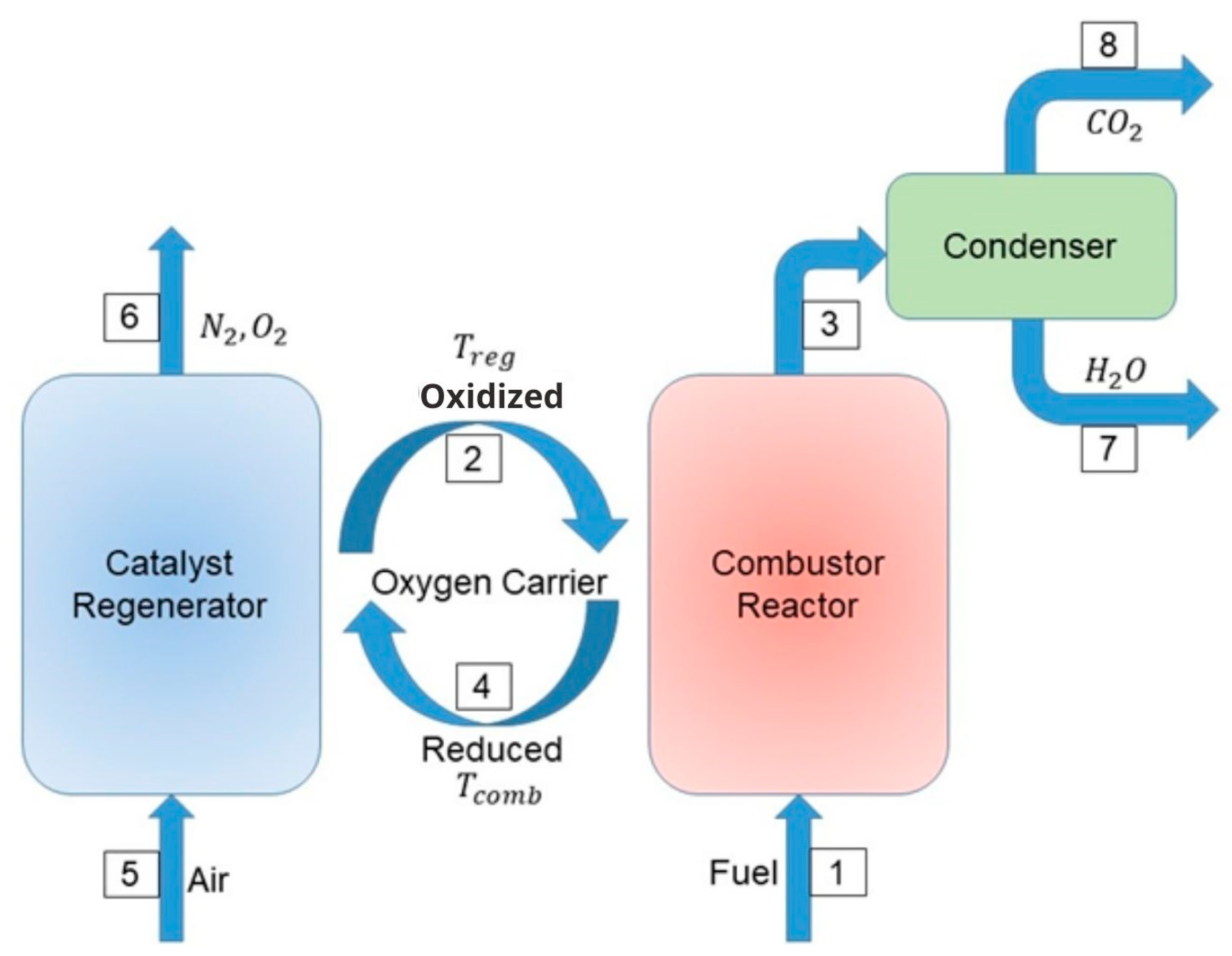
2.1. The Chemical Looping Combustion Process

A typical CLC process consists primarily of the combustor (Figure 1). Here, the fuel (stream 1) is exposed to the oxygen contained in the metal lattice of some solid carrier (streams 2 and 4), which also functions as combustion catalyst. The fuel is completely oxidized, and simultaneously the catalyst is reduced. The most interesting feature of this sequence of steps is that the exhaust gases (stream 3) contain only carbon dioxide and water (ideally), both of which are easily separable, leaving CO2 pure and ready as a reagent. As a second step, in the regenerator (Figure 1), the reduced catalyst is oxidized (stream 4) using oxygen from an air current (stream 5). Thus, the emissions from this second reactor are, ideally, nitrogen plus the oxygen that has been fed as excess. In the ideal case, complete oxidation of the fuel is observed, and the gaseous emissions did not mix the carbon dioxide with nitrogen from the air, this nitrogen will be out of the process in the stream 6.
As the CLC process requires effective interaction between gas and solids, as well as the transfer of solid material between regenerator and combustion reactors, the utilization of two fluidized beds that are interconnected has been suggested [7]. The overall heat produced by the reactions in both reactors ideally matches that generated by conventional combustion, where air directly interacts with the fuel, and N2 and CO2 are blended in the exhaust. The primary limitation of chemical looping combustion lies in the significant chemical and thermal stresses imposed on oxygen carriers during each reduction and oxidation cycle [8]. These stresses have the potential to diminish the efficiency and mechanical resilience of oxygen carriers after only a few usage cycles. Therefore, there is a need to conduct a comparative analysis of oxygen carriers to identify the most suitable candidate that enhances combustion efficiency and demonstrates prolonged operational lifetimes.
Jin and Ishida [9] outlined the primary allowable reactions, using gases from coal gasification as fuel. In this scheme, ‘M’ is used to represent metal (Equations (1) and (2)). However, this scheme for the combustion reactions is an ideal representation since it considers a metal oxide particle to have an oxygen-carrying capacity equivalent to 1.0, which is not the case, as it is analyzed below.
H2 + MO → H2O + M
CO + MO→ CO2 + M

2.2. The Process of Selecting an Oxygen Carrier

The choice of oxygen-carrying material plays a pivotal role in determining the energy efficiency of the CLC system. Oxygen carriers primarily composed of iron, nickel and copper have emerged as the most promising candidates to be used in the CLC process [10]. Typically, the operational framework of a carrier involves embedding the metal oxide within an inert porous substrate, enhancing specific surface area for reactions, mechanical durability, and resistance to abrasion [8,11]. Evaluating any metal oxide as a potential oxygen carrier necessitates meeting various criteria [12,13].
To be considered a good oxygen carrier, a catalyst must exhibit the following characteristics:
(a)
Selective for reduction and oxidation products.
(b)
Demonstrating stability throughout multiple combustion-regeneration cycles.
(c)
Mechanically resistant to the stress of reaction conditions in each reactor.
(d)
Being economically feasible and environmentally friendly.
Additionally, it is highly important to select an inert support for the metal oxide used in the process, which fulfills two functions. On the one hand, it increases the surface area of the conveyor in the system and on the other hand, it decreases the loss of such material due to drag between the reactors. This will favor, together with the evaluation of the useful life of the material, a low replacement rate. There are minerals that have been studied in recent years and are attractive for the process since they do not require support, in this field, one of the most promising materials is ilmenite.
Oxygen carriers (OCs) can be categorized into several types. One classification is based on their origin, distinguishing between natural OCs (such as ilmenite) and synthetic OCs. Another criterion considers active compounds composition (e.g., NiO or ((Mn, Fe)2O3) and their structural configuration (such as perovskites) [14]. The selection of carriers usually is based on their oxygen transfer efficiency and reactivity, which is intrinsically dependent on a good distribution of the metal oxides on a suitable support, ensuring stability during combustion cycles. Some researchers have explored combinations like iron oxide with an inert support enveloped by magnesium to achieve the best properties, including high resistance to attrition and reactivity. Fe2O3 supported on MgAl2O4, for instance, has demonstrated significant reactivity in fluidized bed reactors [15]. While NiO-based carriers have shown promising results at pilot scale, their toxicity and environmental impact raise concerns [6].
Oxygen transport capacity is assessed by measuring the oxygen transferred to the fuel, following the stoichiometric ratio to completely oxidize the fuel to CO2 and H2O (Equation (3)) [16].
O x y g e n   T r a n s p o r t   C a p a c i t y   = M x O y M x O y 1 M x O y
The ilmenite is composed of a blend of iron oxides and titanium, exhibiting excellent efficiency in converting both solid and gaseous fuels [17]. Utilizing ilmenite as an oxygen carrier, hematite (FeTiO3) is the most reduced compound while pseudobrookite (Fe2TiO5) represents the oxidized form, contrary to what might be assumed, subjecting ilmenite particles to thermal pretreatment enhances their reactivity., Therefore, a pre-oxidized ilmenite is preferable to a fresh one as the initial material. Different varieties of ilmenite have been examined, coming from Norway, South Africa and Canada, each having a different composition [18]. Ilmenite is heat-treated to change its composition as can be seen in Table 1. Here, the quantity of ferric oxide will increase when activated while pseudobrookite is reduced by about 20%.
The reaction within the combustor can be endothermic or exothermic depending on the metal oxide chosen, whereas the oxidation process of the carrier in the regenerator is consistently exothermic. The oxygen transfer capacity of oxygen carriers is dependent on both the active metal oxide content and the type of metal oxide used. Consequently, the oxygen transport capacity (R0) is higher for pure metal oxides like NiO/Ni (R0 = 0.210) and CuO/Cu (R0 = 0.200) than for Fe2O3/Fe3O4 (R0 = 0.0341) [19].
The reduction of ilmenite components, such as pseudobrookite and hematite, with gaseous fuels, like H2 ((4) and (5)) and CO ((6) and (7)) and the corresponding regeneration of the oxides ((8) and (9)) is carried out in the reactive system, as shown in Equations (4)–(9).
F e 2 T i O 5 + T i O 2 + H 2 2 F e T i O 3 + H 2 O
3 F e 2 O 3 + H 2 2 F e 3 O 4 + H 2 O
F e 2 T i O 5 + T i O 2 + C O 2 F e T i O 3 + C O 2
3 F e 2 O 3 + C O 2 F e 3 O 4 + C O 2
4 F e T i O 3 + O 2 2 F e 2 T i O 5 + 2 T i O 2
4 F e 3 O 4 + O 2 6 F e 2 O 3
The proposed operating temperature for a reactive CLC system has been limited to 950 ± 8 °C [8,20]. Ilmenite has a particular characteristic, throughout the cycles its performance in the process increases, it is estimated that in the first 100 cycles the “activated” ilmenite will reach its optimum point of operation [18]. In prior studies carried out to the material, it has been found that throughout the process an accumulation of iron is generated on the surface of the carrier while the titanium present in the oxides within the ore tends to accumulate in the center, this behavior can be seen in Figure 2 adapted from what has been presented by research groups in the area. Here, the gray specie in the surface correspond to the iron accumulated through the cycles of the ilmenite in the oxidation process. Furthermore, this accumulation is possible in two ways. A homogeneous iron layer or iron islands along the ore. It is important to note that when ilmenite is exposed to these temperatures, the system can be considered free of water, so the water present will be given by the reaction with the syngas.

2.3. Syngas

Syngas can be produced from fossil fuels or biomass. It is one of the crucial chemical platforms to produce many value-added compounds. Syngas is a mixture of carbon monoxide (CO) and hydrogen (H2) obtained from different processes, e.g., gasification; it can usually be found in the ratio H2/CO = 2 [21,22]. This gaseous product also contains carbon dioxide (CO2), small amounts of methane (CH4), hydrogen sulfide (H2S), ammonia (NH3) and hydrocyanic acid (HCN) [23].
Gasification is a thermal process that transforms organic matter into syngas, biofuels, and solid residues, where the most important parameters are the amount of water supplied to the process, the operating temperature, as well as the catalyst chosen for it. Such organic matter can be obtained from agriculture, aquatic and terrestrial waste. The process involves the decomposition of macromolecules in an oxygenated environment [24].
If the syngas obtained from the process exhibits a (H2/CO) ratio greater than three, it is considered a hydrogen-rich gas, and it may be proposed to separate pure hydrogen as a product. On the other hand, if the gas exhibits a (H2/CO) ratio between 2 and 3, the gas can be processed using the Fischer–Tropsch process, which can produce synthetic hydrocarbons. Finally, if this gas exhibits a ratio lower than two, it is considered a lean gas and the separation of its components would be more complex, so coupling to a chemical looping combustion system aiming for a total oxidation becomes an attractive option. This information is exemplified in Figure 3.

3. Methodology

There are two routes of reaction when a syngas stream is used with ilmenite as oxygen carrier. A thermodynamic analysis is required to clearly explain the chemical combustion process and to obtain the difference between absence or presence of a preheat step in the inlet air stream to the regenerator reactor.

3.1. Heat of Formation

The heat of formation for each of the species involved in the CLC process when ilmenite is used can be found in the literature. This property is shown in Table 2. This displays the heat capacities of the most important species present in the mineral studied. It should be noted that all heats of reaction for both iron oxides and iron-titanium compounds are endothermic, which is the most important approach in order not to negatively impact energy generation through this proposed combustion.
In addition, all the compounds involved in the two reactors must be considered, taking the thermodynamic properties from bibliographic sources and taking those conditions from the reference temperature to the proposed operating temperature (for ilmenite it is usually 950 °C) [8]. Thus, applying Kirchhoff’s law, a real picture of the energy performance of the reaction at any temperature is obtained. Data collection is shown in Table 3.

3.2. Thermodynamic Analysis

Several research groups have proposed the reaction stoichiometry for chemical looping combustion; however, these can be further analyzed using thermodynamics, specifically by calculating the Gibbs free energy. Using the data from Section 2.1 and Section 2.3, the spontaneity of the reactions involved in both reactors can be compared with the reaction pathway for all the oxygen carriers under consideration.
A spontaneous process occurs without external energy input and can proceed at varying rates. In this way, the following assumptions apply:
-
If the Gibbs free energy value is less than zero, the reaction is exergonic and will proceed spontaneously in the forward reaction to form products.
-
If the Gibbs free energy value is higher than zero, the reaction is endergonic, therefore it will require an input of energy to occur, being considered an unnatural or non-spontaneous reaction in the pathway described.
-
If the Gibbs free energy value is equal to zero, the system will be in equilibrium and both the concentration of products and reactants will remain constant.
The energy balance (Equation (10)) considers the system to be pseudo-homogeneous and stationary, using 298.15 K as the reference temperature. For practical purposes, it is subdivided into the energy balance in the combustor (Equation (11)) and the energy balance in the regenerator (Equation (12)).
A c u m u l a t i o n = I n l e t O u t l e t G e n e r a t i o n
0 = n ˙ 1 298.15 T 1 C ^ p 1 · d T + n ˙ 2 298.15 T 2 C ^ p 2 · d T n ˙ 3 298.15 T 3 C ^ p 3 · d T n ˙ 4 298.15 T 4 C ^ p 4 · d T + H c o m b 0 · ε 1 + Q ˙ c o m b
0 = F 4 h ^ 4 + n ˙ 4 298.15 T C ^ p 1 · d T + F 5 h ^ 5 + n ˙ 5 298.15 T C ^ p 5 · d T ( F 2 h ^ 2 + n ˙ 2 298.15 T C ^ p 2 · d T ) ( F 6 h ^ 6 + n ˙ 6 298.15 T C ^ p 6 · d T ) + H r e g 0 · ε 1 + Q ˙ r e g

4. Results and Discussion

A stoichiometric mass balance was performed for the combustor (Equations (4)–(7)) and the regenerator (Equations (8) and (9)), based on a syngas stream (H2/CO = 1) with a flow rate of 200 mol/h and considering the oxygen carrier capacities as 6.7% and 3.3% for pseudobrookite and ferric oxide, respectively. The results obtained from this analysis are shown first for the combustor in Table 4 and Table 5, while Table 6 show the results of the mass balances in the regenerator. It is important to note that there are two proposed reaction routes, one where the oxygen carrier is the pseudobrookite, while the other reaction route is leaded by ferric oxide. Nevertheless, these calculations are supported in the assumption of total conversion of the syngas stream.
The same analysis was performed for the ferric oxide pathway where the hematite reaction with oxygen is given in the combustor. A summary of results obtained is presented in Table 5. It is essential to mention that as the oxygen carrying capacity of this compound is lower, thus, a greater amount of carrier is required for the reaction to take place.
Similarly, analysis on the regenerator is carried out in order to calculate the theoretical oxygen required for carrier regeneration. The composition of the air will be taken as 21% oxygen, 79% nitrogen. Equations (8) and (9) are used to describe both routes, and the summary of the results is shown in Table 6. The air required for both routes is added together at the table because both reactions occur in parallel. Therefore, describing them as a single system is more appropriate.
The energy balance was carried out considering 950 °C as the operating temperature in both reactors since, according to researchers such as Hossain and de Lasa [11], the closer the temperature interval between reactors, the greater the total conversion in the system. Table 7 shows the results obtained for both reaction paths in kW. The amount of heat in the regenerator is the same regardless of the fuel, applying only in this case, since stoichiometry is the same for hydrogen and carbon monoxide and neither of these is involved in the regenerator, so the only thing that will change is the amount of heat in the combustor. The second route from the hematite/ferric oxide complex appears to be more attractive as it generates a balance of 217.15 kW. Thus, the next step should be, evaluating the equilibrium constant and the spontaneity of the reaction from thermodynamic data at the proposed operating temperature.

4.1. Analysis of the Feasibility of Using Ilmenite for Total Oxidation of Syngas in a CLC Process

According to the second law of thermodynamics, Gibbs’ free energy can determine the spontaneity of a reaction, as well as the direction in which it takes place or whether it is in equilibrium. The second law of thermodynamics asserts that if the entropy of the universe increases (ΔS > 0), then a spontaneous process occurs. Additionally, Gibbs free energy can be defined at a constant pressure and temperature as ΔG = ΔH − TΔS. Thus, when the ΔG is negative, we are faced with a spontaneous process in the original sense of the reaction, forming products. Table 8 shows a concentrate of the thermodynamic data with both reaction paths for each of the syngas components. It should be remembered that the reactions in the regenerator are the same for both fuels, so the value of the regenerator will be the same.
At the end of this analysis, it can be concluded that the first route for oxidation of syngas from pseudobrookite is not spontaneous in the regenerator, while in the combustor it is. However, by calculating the change of Gibbs free energy throughout the system, it will be positive with both CO and H2. On the other hand, the calculation of the equilibrium constants at this point allows us to verify the zero reactivity in the regenerator, since the K has a value of 3.27 × 10−65 with any of the components of the syngas. The oxidation route from ferric oxide and hematite promises to be much more viable, as it is a spontaneous reaction according to its negative ΔG and the provisions of Section 2.1. Another interesting fact obtained from this study is the change of total enthalpy in the system with the second reaction path, which will be slightly higher in case of using carbon monoxide compared to oxygen, so we could say that a syngas stream with a higher CO content will have a better performance. This analysis confirms the information presented in Figure 2 by other researchers such as Knutsson, Rhida, among others. As the cycles of the reaction increase, ilmenite changes its structure, as pseudobrookite does not regenerate, while ferric oxide will be the dominant pathway. This justifies the accumulation of iron on the surface of the oxygen carrier.

4.2. Implementation of a Syngas Stream at 650 °C

Up to this point, it has been demonstrated that ilmenite represents an improvement in terms of the decrease in heat required in the implementation of chemical looping combustion process. Syngas was evaluated as a potential fuel for CLC process. Therefore, the corresponding energy balance will be developed, considering a syngas with a ratio H2/CO = 1 obtained from a gasifier at 650 °C, obtaining oxygen from the air at 25 °C. Table 9 shows the summary of the thermodynamic values obtained, where an increase in the equilibrium constant in the combustor can be found, which goes from 21.050 to a value of 29.322 for the reaction path shown to be feasible as a function of the free Gibbs energy in the system. while the equilibrium constant in the regenerator remains in the order of 10−65, which proves the irreversibility of the pseudobrookite path. Finally, the equilibrium constant in the regenerator for the ferric oxide route is also favored by up to 500,000 units.

4.3. Heterogeneous Reaction Mechanism for the CLC System Proposed

There are two ways of chemical kinetics to understand a reaction, the global homogeneous and the heterogeneous, which aims to involve the active sites of the solid catalyst that will be in contact with the reactants in the gas phase, first forming an adsorbed site, then carrying out the reaction and then the desorption of the final product to be incorporated into the reactor output stream. There are solid mass catalysts in which 100% of the mass present is considered as a catalyst, on the other hand there are also supported catalysts; There, the active species are attached to a solid matrix known as a support.
Considering effective kinetics, several steps should be taken into account as shown below:
  • Reagent transfer at the interface.
  • Diffusivity of the reagent.
  • Adsorption of the reagent into the catalyst.
  • Surface reaction (interaction between sites).
  • Desorption.
  • Diffusivity of the product.
  • Product transfer at the interface.
Among the steps mentioned, points 3–5 that will be considered as intrinsic heterogeneous kinetics, within the studies carried out in this area are the Langmuir-Hinshelwood–Hougen-Watson (LHHW) models. Considered the base model of heterogeneous kinetics, which proposes the interaction described in the previous seven points, published in the twentieth century. Later, there are specific studies such as the Ealy-Riley kinetics, which is a simplification of what is proposed in the LHHW, since it considers that there is only one type of active sites and that they are uniformly distributed in the system. Furthermore, the Mars van Krevelen model, that proposes an oxidation-reduction mechanism in the active sites.
The development of the reaction mechanism of oxidation reactions in the CLC process between syngas and ilmenite in the combustor is presented below, in a Mars van Krevelen model.
Nomenclature:
L P = P s e u d o b r o o k i t e
L T = T i t a n i a
L I = I l m e n i t e
Proposal 1: One hydrogen is adsorbed on the pseudobrookite and the other on the Titania.
Step 1: Adsorption of hydrogen into LP:
L P + 1 2 H 2 H · L P r a b d H · L P = k 1 C L P C H 2 1 2 k 1 C H · L P
Step 2: Adsorption of hydrogen in LT:
L T + 1 2 H 2 H · L T r a b d H · L T = k 2 C L T C H 2 1 2 k 2 C H · L T
Step 3: Water Desorption:
H · L P + H · L T 2 L I + H 2 O r d e s H 2 O = k 3 C H · L P C H · L T k 3 C L I 2 C H 2 O
Equilibrium constants are involved in the reactions to determine the equations corresponding to the occupied sites by hydrogen.
K a d s H · L P = k 1 k 1 = C H · L P C L P C H 2 1 2 ,   Thus   C H · L P = K a d s H · L P C L P C H 2 1 2
K a d s H · L T = k 2 k 2 = C H · L T C L T C H 2 1 2 ,   Thus   C H · L T = K a d s H · L T C L T C H 2 1 2
K d e s H 2 O = k 3 k 3 = C L I 2 C H 2 O C H · L P C H · L T ,   Thus   C L I = K d e s H 2 O C H · L P C H · L T C H 2 O 1 2
Substituting Equations (16)–(18) to eliminate adsorbed gas sites.
C L I = K d e s H 2 O K a d s H · L P K a d s H · L T C L P C L T C H 2 C H 2 O 1 2
So, the balance of total sites will be as shown in Equation (19).
C T = C L P + C L T + C H · L P + C H · L T + C L I
They will assume instantaneous desorption, so the sites occupied by the fuel are considered as zero. Thus, the total sites will be a function of the concentration of the compounds involved in the reaction in the combustor.
C T = C L P + C L T + K d e s H 2 O K a d s H · L P K a d s H · L T C L P C L T C H 2 C H 2 O 1 2
According to the general combustion reaction showed in Equation (4).
The rate of the reaction is given by equation:
r A = k r 1 C L P C L T C H · L P C H · L T k r 2 C L I 2 C H 2 O
Rearranging the equation with the assumption of adsorbed sites and substituting the ilmenite sites will yield:
r A = k r 1 C L P C L T k r 1 K d e s H 2 O K a d s H · L P K a d s H · L T C L P C L T C H 2 C H 2 O ( 1 2 ) 2 C H 2 O
Considering
K d e s H 2 O K a d s H · L P K a d s H · L T = K c o m b   thus   r A = k r 1 C L P C L T k r 1 K c o m b C L P C L T C H 2
Now from the second reaction involved in the combustion reactor, where ferric oxide will be responsible for the total oxidation of the syngas as shown in Equation (23).
3 F e 2 O 3 + H 2 2 F e 3 O 4 + H 2 O
Nomenclature:
L O F = F e r r i c   O x i d e
L H = H e m a t i t e
Step 1: Fuel Adsorption
3 L O F + H 2 3 H 2 · L O F r a d s H 2 = k 1 C L O F 3 C H 2 k 1 C H 2 · L O F 3
Step 2: Water Desorption
3 H 2 · L O F 2 L H + H 2 O r d e s H 2 O = k 2 C H 2 · L O F 3 k 2 C L H 2 C H 2 O
Equilibrium constants are involved in the reactions to determine the equations corresponding to the sites occupied by hydrogen.
K a d s H 2 · L O F = k 1 k 1 = C H 2 · L O F 3 C L O F 3 C H 2 ,   Thus   C H 2 · L O F = ( K a d s H 2 · L O F C L O F 3 C H 2 ) 1 / 3
K d e s H 2 O = k 2 k 2 = C L H 2 C H 2 O C H 2 · L O F 3 ,   Thus   C L H = ( K d e s H 2 O C H 2 · L O F 3 C H 2 O ) 1 2
Equation (26) is substituted in Equation (27) to remove adsorbed sites from the fuel.
C L H = ( K d e s H 2 O K a d s H 2 · L O F C L O F 3 C H 2 C H 2 O ) 1 2
The total concentration of available sites will be set out in Equation (28).
C T = C L O F + C L H + C H 2 · L O F
Spontaneous desorption is assumed, so the total free sites will be a function of ferric oxide and hematite H 2 · L O F .
C T = C L O F + ( K d e s H 2 O K a d s H 2 · L O F C L O F 3 C H 2 C H 2 O ) 1 2
The overall reaction rate is expressed in Equation (30).
r A = k r 2 C L O F 3 C H 2 · L O F k r 2 C L H 2 C H 2 O
Rearranging the equation with the assumption of adsorbed sites and substituting hematite sites will yield:
r A = k r 2 C L O F 3 k r 2 K d e s H 2 O K a d s H 2 · L O F C L O F 3 C H 2
Considering:
K d e s H 2 O K a d s H 2 · L O F = K c o m b 2   thus   r A = k r 2 C L O F 3 k r 2 K c o m b 2 C L O F 3 C H 2
Proposed Reaction Mechanism for Carrier Recovery (Regenerator)
It should be noted that, for both fuels, both CO and H2 the mechanism will be similar since the stoichiometry of the reaction is the same. In addition, it should be remembered that the proposal of chemical cycle combustion for a syngas becomes attractive for a lean syngas feed (H2/CO ≈ 1). However, the mechanism of the reactions that occur in the regenerator must be developed, which have two routes according to the literature. However, it was demonstrated by thermodynamic analysis that the production of pseudobrookite is a non-spontaneous reaction, so the reaction is not reversible. Therefore, an analysis of ferric oxide regeneration should directly follow, as shown below:
4 F e 3 O 4 + O 2 6 F e 2 O 3
Step 1: Adsorption of hematite to LH:
4 L H + O 2 4 L H · O 2 r a d s L H · O 2 = k 1 C L H 4 C O 2 k 1 C L H · O 2 4
Step 2: Ilmenite Production
4 L H · O 2 6 L O F r p r o d L O F = k 2 C L H · O 2 4 k 2 C L O F 6
An instantaneous reaction will be assumed, so the adsorbed sites can be substituted with Equation (32), yielding (34).
4 L H + O 2 6 L O F r A = k 3 C L H 4 C O 2 k 3 C L O F 6
Taking into consideration the equilibrium constant of the system, Equation (35) will be obtained.
K r 3 = k 3 k 3 = C L O F 6 C L H 4 C O 2
From Equation (35), the concept of reaction coordinate can be applied to generate an equation involving the equilibrium constant in the system with the advance of the reaction. An equation must be generated for the mole fraction of each compound involved in the reaction (Equations (36)–(38)).
y L H = n L H 4 ε n T + ε
y O 2 = n O 2 ε n T + ε
y L O F = n L O F + 6 ε n T + ε
Molar fractions are substituted in the equation of the equilibrium constant (35).
K r 3 = ( n L O F + 6 ε n T + ε ) 6 n L H 4 ε n T + ε 4 ( n O 2 ε n T + ε ) = ( n L O F + 6 ε ) 6 ( n T + ε ) ( n O 2 ε ) ( n L H 4 ε ) 4
Here:
  • n T = number of total moles fed to the system;
  • n L O F = moles of ferric oxide fed to the system;
  • n L H = moles of hematite present in the system;
  • n O 2 = moles of oxygen fed to the regenerator;
  • ε = reaction coordinate;
  • K r 3 = regenerator equilibrium constant.

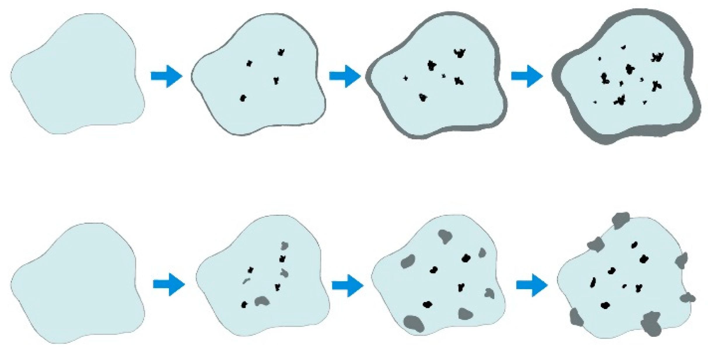
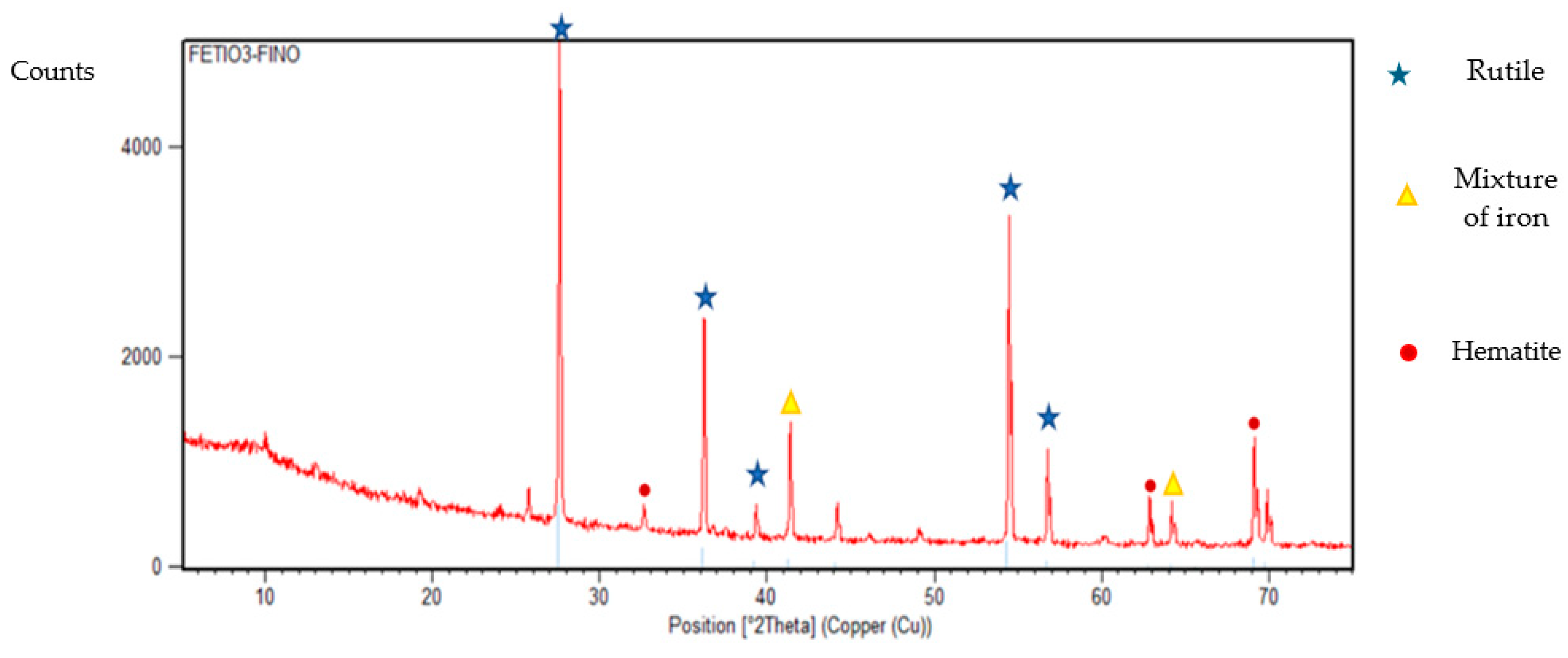
4.4. Preparation of Synthetic Ilmenite at the Laboratory Level

Ilmenite synthesis was conducted using the sol-gel method, using as precursors, nine-hydrated Iron Nitrate (III) and Titanium Butoxide (IV). A hydrolysis solution 16/4 water-ethanol with nitric acid and isopropanol as dispersant medium, which was heated to a temperature of 60 °C and in constant agitation. Once this temperature was reached, titanium butoxide (IV) was added. Working at constant temperature and stirring for an hour, in order to achieve a homogeneous system. After this time, the mixture was cooled to a temperature of 2–3 °C, to proceed to impregnate the hydrolysis solution with the Iron Nitrate (III) by constant drip, maintaining the agitation and temperature of the system, during this period the gel began to form, when it was formed, the agitation was suspended and it was left to age for 24 h at a temperature of −3 °C. After this time, the gel was placed in a watch glass to begin drying for 2 h at 120 °C. A powder with a grain size between 425–710 μm was obtained and calcined at a temperature of 950 °C for two hours, the heating rate was set at 12.9 °C/min. The material obtained was analyzed by X-ray spectroscopy and the following results were obtained (Figure 4).
After calcinating the ilmenite sample, the amount of iron oxides present is notorious, the rutile generated and not used in the regeneration of the pseudobrookite is also present. In addition, small peaks of hematite are shown, a compound that decomposes in the regenerator reactor in the presence of air to recover ferric oxide that will be used again in the next syngas oxidation cycle.

5. Conclusions

According to the proposed reaction pathways for ilmenite, one of them is not reversible, so the controlling reaction in the system will be with the hematite-ferric oxide pair, which increases the capacity of the carrier throughout the cycles as proposed in Figure 2. There is null regeneration of pseudobrookite, being the dominant oxygen carrier ferric oxide as verified through thermodynamics. In addition, according to the data obtained in the ilmenite, generated through the sol-gel technique and characterized by XDR, an increase in the amount of ferric oxide available once the ilmenite was calcined (950 °C) is shown. Finally, if the fuel came from a gasifier at a temperature of approximately 650 °C, an amount of 35,000 kW/kmol of syngas used is obtained, assuming the H2/CO = 1 ratio. It is important to mention that the present study was developed considering a cycle, however, the number of cycles that are reached in an hour depends on the nature of the oxygen carrier, as well as the reaction rate. To make a more appropriate proposal, it is necessary to work on a scale model in a reactor.

Author Contributions

Conceptualization: G.S.F.-C., M.A.P.-M. and R.M.-Y. Methodology: G.S.F.-C., R.M.-Y. and F.N.-R. Software: M.A.P.-M. and G.J.-G. Validation: R.H.-A., F.N.-R. and J.E.-V. Formal analysis: M.A.P.-M. and R.M.-Y. Investigation: G.S.F.-C., M.A.P.-M. and R.M.-Y. Resources: R.M.-Y. and J.E.-V. Data curation: G.J.-G., F.N.-R. and R.H.-A. Writing—original: G.S.F.-C., M.A.P.-M., R.M.-Y., G.J.-G., F.N.-R., J.E.-V. and R.H.-A. Draft preparation: G.S.F.-C., M.A.P.-M. and R.M.-Y. Writing—review and editing, G.S.F.-C., M.A.P.-M. and R.M.-Y. Visualization: G.S.F.-C., M.A.P.-M. and R.M.-Y. Supervision: R.M.-Y., J.E.-V., G.J.-G., F.N.-R. and R.H.-A. Project administration R.M.-Y. All authors have read and agreed to the published version of the manuscript.

Funding

This research was funded by Consejo Nacional de Humanidades Ciencia y Tecnología (CONAHCYT), grant 861753 & 861765, and financial support was provided by CIC-UMSNH (Project 20.20).

Data Availability Statement

The data that support the findings of this study are available from the corresponding author, upon reasonable request.

Acknowledgments

G.J.-G., R.H.-A., F.N.-R., J.E.-V. and R.M.-Y. greatly appreciate research system grants (SNII-CONAHCYT).

Conflicts of Interest

The authors declare no conflicts of interest.

References

  1. Gao, P.; Li, F.; Xiao, F.; Zhao, N.; Wei, W.; Zhong, L.; Sun, Y. Effect of hydrotalcite-containing precursors on the performance of Cu/Zn/Al/Zr catalysts for CO2 hydrogenation: Introduction of Cu2+ at different formation stages of precursors. Catal. Today 2012, 194, 9–15. [Google Scholar] [CrossRef]
  2. Koytsoumpa, E.I.; Bergins, C.; Kakaras, E. The CO2 economy: Review of CO2 capture and reuse technologies. J. Supercrit. Fluids 2018, 132, 3–16. [Google Scholar] [CrossRef]
  3. Sullivan, I.; Goryachev, A.; Digdaya, I.A.; Li, X.; Atwater, H.A.; Vermaas, D.A.; Xiang, C. Coupling electrochemical CO2 conversion with CO2 capture. Nat. Catal. 2021, 4, 952–958. [Google Scholar] [CrossRef]
  4. World Nuclear Association. Carbon Dioxide Emissions from Electricity. 2022. Available online: https://www.world-nuclear.org/information-library/energy-and-the-environment/carbon-dioxide-emissions-from-electricity.aspx (accessed on 30 November 2022).
  5. Arjmand, M.; Leion, H.; Mattisson, T.; Lyngfelt, A. Investigation of different manganese ores as oxygen carriers in chemical-looping combustion (CLC) for solid fuels. Appl. Energy 2015, 113, 1883–1894. [Google Scholar] [CrossRef]
  6. Pérez-Méndez, M.A.; Fraga-Cruz, G.S.; Jiménez-García, G.; Huirache-Acuña, R.; Nápoles-Rivera, F.; Maya-Yescas, R. Macroscopic analysis of chemical looping combustion with ilmenite versus conventional oxides as oxygen carriers. Int. J. Chem. React. Eng. 2023, 21, 511–520. [Google Scholar] [CrossRef]
  7. Linderholm, C.; Mattisson, T.; Lyngfelt, A. Long-term integrity testing of spray-dried particles in a 10-kW chemical-looping combustor using natural gas as fuel. Fuel 2009, 88, 2083–2096. [Google Scholar] [CrossRef]
  8. Adanez, J.; Abad, A. Chemical-looping Combustion: Status and Research Needs. Proc. Combust. Inst. 2019, 37, 4303–4317. [Google Scholar] [CrossRef]
  9. Jin, H.; Ishida, M. A new type of coal gas fueled chemical-looping combustion. Fuel 2004, 83, 2411–2417. [Google Scholar] [CrossRef]
  10. Adánez, J.; Cuadrat, A.; Abad, A.; Gayán, P.; de Diego, L.F.; García-Labiano, F. Ilmenite activation during consecutive redox cycles in chemical-looping combustion. Energy Fuels 2010, 24, 1402–1413. [Google Scholar] [CrossRef]
  11. Hwang, J.H.; Son, E.N.; Lee, R.; Kim, S.H.; Baek, J.I.; Ryu, H.J.; Lee, K.T.; Sohn, J.M. A thermogravimetric study of CoTiO3 as oxygen carrier for chemical looping combustion. Catal. Today 2018, 303, 13–18. [Google Scholar] [CrossRef]
  12. Hossain, M.M.; de Lasa, H.I. Chemical-looping combustion (CLC) for inherent CO2 separations—A review. Chem. Eng. Sci. 2008, 63, 4433–4451. [Google Scholar] [CrossRef]
  13. Ipsakis, D.; Heracleous, E.; Silvester, L.; Bukur, D.B.; Lemonidou, A.A. Reduction and oxidation kinetic modeling of NiO-based oxygen transfer materials. Chem. Eng. J. 2017, 308, 840–852. [Google Scholar] [CrossRef]
  14. Görke, R.; Marek, E.; Donat, F.; Scott, S. Reduction and oxidation behavior of strontium perovskites for chemical looping air separation. Int. J. Greenh. Gas Control. 2020, 94, 102891. [Google Scholar] [CrossRef]
  15. Mattisson, T.; Johansson, M.; Lyngfelt, A. Multicycle Reduction and Oxidation of Different Types of Iron Oxide ParticlesApplication to Chemical-Looping Combustion. Energy Fuels 2004, 18, 628–637. [Google Scholar] [CrossRef]
  16. Czakiert, T.; Krzywanski, J.; Zylka, A.; Nowak, W. Chemical Looping Combustion: A Brief Overview. Energies 2022, 15, 1563. [Google Scholar] [CrossRef]
  17. Berguerand, N.; Lyngfelt, A. Design and operation of a 10 kWth chemical-looping combustor for solid fuels–Testing with South African coal. Fuel 2008, 87, 2713–2726. [Google Scholar] [CrossRef]
  18. Knutsson, P.; Linderholm, C. Characterization of ilmenite used as oxygen carrier in a 100 kW chemical-looping combustor for solid fuels. Appl. Energy 2015, 157, 368–373. [Google Scholar] [CrossRef]
  19. Lyngfelt, A.; Leckner, B.; Mattisson, T. A Fluidized-Bed Combustion Process with Inherent CO2 Separation; Application of Chemical-Looping Combustion. Chem. Eng. Sci. 2001, 56, 3101–3113. [Google Scholar] [CrossRef]
  20. Azis, M.M.; Jerndal, E.; Leion, H.; Mattisson, T.; Lyngfelt, A. On the evaluation of synthetic and natural ilmenite using syngas as fuel in chemical-looping combustion (CLC). Chem. Eng. Res. Des. 2010, 88, 1505–1514. [Google Scholar] [CrossRef]
  21. Ridha, F.N.; Duchesne, M.A.; Lu, X.; Lu, D.Y.; Filippou, D.; Hughes, R.W. Characterization of an ilmenite ore for pressurized chemical looping combustion. Appl. Energy 2016, 163, 323–333. [Google Scholar] [CrossRef]
  22. Molino, A.; Nanna, F.; Ding, Y.; Bikson, B.; Braccio, G. Biomethane production by anaerobic digestion of organic waste. Fuel 2013, 103, 1003–1009. [Google Scholar] [CrossRef]
  23. Pacheco, M.; Moura, P.; Silva, C. A Systematic Review of Syngas Bioconversion to Value-Added Products from 2012 to 2022. Energies 2023, 16, 3241. [Google Scholar] [CrossRef]
  24. Chang, Y.-J.; Chang, J.-S.; Lee, D.-J. Gasification of biomass for syngas production: Research update and stoichiometry diagram presentation. Bioresour. Technol. 2023, 387, 129535. [Google Scholar] [CrossRef] [PubMed]
  25. Smith, J.M.; Van Ness, H.C.; Abbott, M.M.; Swihart, M.T. Introduction to Chemical Engineering Thermodynamics; McGraw-Hill: Singapore, 1949. [Google Scholar]
  26. Collieu, A.M.; Powney, D.J.; Girifalco, L.A.; Herman, H. The mechanical and thermal properties of materials and statistical physics of materials. Phys. Today 1975, 28, 51–52. [Google Scholar] [CrossRef]
Figure 1. Schematics of the Chemical Looping Combustion process [6].
Processes 12 01033 g001
Figure 2. Representation of iron migration in ilmenite exposed to the CLC process with increasing residence time, adapted from [18].
Processes 12 01033 g002
Figure 3. Decision scheme for the choice of post-gasification process.
Processes 12 01033 g003
Figure 4. XDR diagram for synthetic ilmenite produced.
Processes 12 01033 g004
Table 1. Physical composition and properties of the ilmenite species [16,18].
CharacteristicNatural Ilmenite OreActivated Ilmenite
Fe2O3 (mass fraction)0.1120.220
Fe2TiO5 (mass fraction)0.5470.385
TiO2 (mass fraction)0.2860.340
Inert (mass fraction)0.0550.055
Mineral Density (kg m−3)41004250
R0, ilm (%)4.03.3
Table 2. Thermodynamic properties of ilmenite compounds [25,26].
Heat ReactionkJ/mol
2 Fe + 3/2O2 → Fe2O3810.3
2 FeO + 1/2O2 → Fe2O3279.5
2 Fe3O4 + 1/2O2 → 3 Fe2O380.9
2FeTiO3 +1/2O2 → Fe2TiO5 + TiO2214.2
Fe2TiO4 + 1/2O2 → Fe2TiO5219.0
2FeTi2O4 + 3/2O2 → Fe2TiO5 + 3TiO2938.6
Calorific CapacitykJ/°C × mol
Hematite (Fe2O3)s0.1398
Magnetite (Fe3O4)s0.2035
Pseudobrookite (Fe2TiO5)s0.2174
Titania (TiO2)s0.0758
Ilmenite (FeTiO3)s0.1353
Table 3. Thermodynamic properties of ilmenite and compounds involved in the CLC process.
Compound Δ H f 0 ( k J m o l ) Δ S f 0 ( k J m o l K ) C p ( k J m o l K )
Fe2TiO5−1565.30.17140.2174
Fe2O3−824.20.08740.1398
FeTiO3−1235.230.12490.1353
Fe3O4−1118.40.14640.2035
TiO2−180.490.1510.0758
CO−110.130.19760.02916
H200.13070.02882
CO2−393.510.213780.03711
H2O−241.820.188830.03358
O200.205130.02935
Table 4. Mass balance in Combustor using pseudobrookite route.
Pseudobrookite RouteCombustor
Input   ( m o l h ) Outlet   ( m o l h )
Compound e F 1 e F 2 s F 3 s F 4
CO100.00.00 = 100 − ε1 = 100(1 − ξ C O ) 0.0
H2100.00.00 = 100 − ε2 = 100(1 − ξ H 2 ) 0.0
Fe2TiO50.02985.00.00.0
TiO20.02985.00.00.0
FeTiO30.00.00.05970.0
CO20.00.0ε2 = 100.00.0
H2O0.00.0ε1 = 100.00.0
Table 5. Mass balance in Combustor for Ferric Oxide route.
Ferric Oxide RouteCombustor
Inlet   ( m o l h ) Outlet   ( m o l h )
Compound e F 1 e F 2 s F 3 s F 4
H2100.00.00=100 − ε1 = 100(1 − ξ H 2 ) 0.0
CO100.00.00=100 − ε2 = 100(1 − ξ C O ) 0.0
Fe2O30.018,181.80.00.0
Fe3O40.00.00.012,121.2
H2O0.00.0ε1 = 100.00.0
CO20.00.0ε2 = 100.00.0
Table 6. Mass balance in the regenerator.
Regenerator
Inlet   ( m o l h ) Outlet   ( m o l h )
Compound e F 4 e F 5 s F 6 s F 2
FeTiO35970.00.00.00.0
Fe2TiO50.00.00.02985.0
TiO20.00.00.02985.0
Fe3O412,121.20.00.00.0
Fe2O30.00.00.018,181.8
N20.017,014.317,014.30.0
O20.04522.80 = 4522.8 − ε20.0
Table 7. Comparison of Heat Required using Syngas in a CLC Process with Ilmenite.
Reaction RouteH2
(Fe2TiO5)
CO
(Fe2TiO5)
H2
(Fe2O3)
CO
(Fe2O3)
Combustor (kW)−342.99−341.02183.35186.40
Regenerator (kW)606.92606.92−400.5−400.5
Total (kW)263.93265.90−217.15−214.1
Table 8. Summary of thermodynamic values for a CLC process with ilmenite and syngas.
Fuel∆Hcomb
(kJ/mol)
∆Hreg
(kJ/mol)
∆Htot
(kJ/mol)
∆Scomb
(kJ/molK)
∆Sreg
(kJ/molK)
∆Stot
(kJ/molK)
H2 (1)−982.9921464.001481.009−0.039653−0.037556−0.077209
H2 (2)40.234−475.809−435.5790.420709−0.2727530.147957
CO (1)−1021.6011464.001442.402−0.077100−0.037556−0.114657
CO (2)−51.696−475.809−527.5050.040498−0.272753−0.232254
Fuel∆Gcomb
(kJ/mol)
Kcomb∆Greg
(kJ/mol)
Kreg∆Gtot
(kJ/mol)
H2 (1)−934.4918.10745 × 10391509.9383.27894 × 10−65575.448
H2 (2)−474.3671.81265 × 1020−142.1911.18168 × 106−616.552
CO (1)−927.2973.99622 × 10391509.9383.27894 × 10−65582.642
CO (2)−101.23221,051 × 104−142.1911.18168 × 106−243.423
Table 9. Summary of thermodynamic values for a CLC process with ilmenite and syngas from a gasifier.
Fuel∆Hcomb
(kJ/mol)
∆Hreg
(kJ/mol)
∆HTot
(kJ/mol)
∆Scomb
(kJ/molK)
∆Sreg
(kJ/molK)
∆Stot
(kJ/molK)
H2 (1)−971.8421454.095482.253−0.01949005−0.055470−0.074960
H2 (2)8.980−472.965−463.9850.36419965−0.2676100.096589
CO (1)−1012.4451454.095441.650−0.06054241−0.055470−0.116012
CO (2)−48.915−472.965−521.8800.04552780−0.267610−0.222083
Fuel∆Gcomb
(kJ/mol)
Kcomb∆Greg
(kJ/mol)
Kreg∆Gtot
(kJ/mol)
H2 (1)−948.0033.06150 × 10401521.9431.00705 × 10−65573.940
H2 (2)−436.4914.37542 × 1018−145.6371.65800 × 106−582.128
CO (1)−938.3931.18992 × 10401521.9431.00705 × 10−65583.550
CO (2)−104.60229,322.8025−145.6371.65800 × 106−250.240
Disclaimer/Publisher’s Note: The statements, opinions and data contained in all publications are solely those of the individual author(s) and contributor(s) and not of MDPI and/or the editor(s). MDPI and/or the editor(s) disclaim responsibility for any injury to people or property resulting from any ideas, methods, instructions or products referred to in the content.

