Article

Characteristic Analysis and Coating Application of the Innovative HVOF System Based on the Digital Model

1
Missile Engineering College, Rocket Force University of Engineering, Xi’an 710025, China
2
Department of Mechanical Engineering, Tsinghua University, Beijing 100084, China
3
Project Management Center, Beijing 100085, China
*
Authors to whom correspondence should be addressed.
Processes 2024, 12(4), 657; https://doi.org/10.3390/pr12040657
Submission received: 28 February 2024 / Revised: 19 March 2024 / Accepted: 22 March 2024 / Published: 26 March 2024
(This article belongs to the Special Issue Latest Research on Advanced Material Surface Treatment Processing)

Abstract

:
In view of the poor working conditions, high cost and time-consuming parameter design of the traditional spray process, an innovative HVOF thermal spray system based on the digital model has been established by this study to improve coating performance and optimize scheme design rapidly. In particular, the digital model of the oxygen/kerosene HVOF spray system is designed on the AMESim multidisciplinary simulation platform for the first time, and the engineering prototype has been successfully developed. Thus, an efficient design method based on the digital model was proposed, according to which the spray control parameters such as oxygen and kerosene flow are obtained conveniently under a combustion chamber pressure of 1.0 MPa and 2.0 MPa, respectively. The error between the simulation and experiment results was generally less than 5%, and the dynamic characteristics of the key components in the actual spray system were well predicted, suggesting that the dynamic response time of the system would generally less than 0.7 s. Additionally, the WC-12Co coatings were deposited under the working conditions of W1.0 and W2.0, respectively, the microhardness of the coating increased about 23% and the corresponding volume wear rate decreased about 18%. The results show that the increase of the pressure of the combustion chamber can further improve the coating performance, which also verifies the feasibility and reliability of the design method. It was concluded that the innovative HVOF system based on the digital model is of great theoretical value and application significance for predicting spray process parameters conveniently and providing excellent coating performance.

1. Introduction

It is well known that thermal spray technology can deposit coatings with special functions such as wear resistance, thermal barrier, lubrication and wave absorption on the surface of mechanical components to improve the performance of equipment. Therefore, the technology is widely used in surface engineering fields such as aerospace equipment manufacturing and maintenance [1,2,3,4]. Among them, the high velocity oxygen-fuel (HVOF) spray technology is often used to prepare tungsten carbide and other cemented carbide coatings due to its unique characteristics of moderate flame temperature and fast gas flow rate [5,6]. Due to their superior wear resistance and environmentally friendly properties, these coatings are promising for replacing hard chromium on mechanical surfaces such as aircraft landing gear [7], rice harvesting blades [8], drilling rigs [9] etc., which means the HVOF spray technology has extremely important engineering value for improving the service life of equipment and reducing production costs [10,11]. Wu et al. [12] investigated the effects of different oxygen/fuel ratios in HVOF on the velocity and temperature evolution of in-flight particles in correlation with the performance of the resulting WC-CoCr coating. The results show that the temperature and velocity of the particles strongly depend on the total flow rate of oxygen and fuel, and the fuel flow rate is more responsive to the changes of particle state than the oxygen flow rate. Żórawski systematically studied the microstructure and tribological properties of the nanostructured WC-12Co coating sprayed by the liquid-fuel HVOF and obtained the conclusion that the average microhardness of the coating exceeds 1160 Hv. The parameters used in the spray process are oxygen and kerosene flow rates of 890 L/min and 22.7 L/min, respectively [13]. It has to be said that the performance of coatings is mainly dependent on the parameters used in the spray process such as the appropriate flame temperature, which can inhibit the decomposition and decarbonization of raw materials, while the higher particle velocity usually promotes the formation of denser coating structures [14,15,16,17]. However, the pressure of the combustion chamber in the spray gun is typically less than 1.0 MPa at present, which directly limits the adjustable parameter range of the HVOF system and subsequently affects the performance of the deposited coating [18,19]. Therefore, it is necessary to study the HVOF thermal spray technology at broader parameter conditions, which will greatly improve coating performance and can even be expected to replace the time-consuming and expensive detonation spray technology. Specifically, during the development of a new thermal spray technology, the process conditions of the equipment need to be optimized repeatedly and iteratively, hence, an efficient parameter design method is urgently needed for practical engineering applications.
Because the concept of digital twins is very popular in the industrial field, the digital model has recently provided an extremely convenient and valuable approach for the analysis and improvement research of the spray process [20,21]. The current simulation research of the HVOF spray system mainly focuses on the classical spray flow field [22,23], the particle deposition process [24,25], etc. These simulation cases based on computational fluid dynamics (CFD) and the finite element method (FEM) provide reference for detailed descriptions of the coating formation process and the prediction of the coating performance [26]. Nonetheless, the inlet boundary conditions of gas flow rate, pressure and particle velocity in the abovementioned, time-consuming models usually lack the simulation data from the source and are mostly defined subjectively, which greatly affect the accuracy of the spray process. A system simulation digital model reflecting the whole state of the spray equipment can solve the difficulty theoretically and will provide an effective method of engineering prototype designs and spray process predictions [21]. In fact, the HVOF spray system works essentially as a small liquid rocket engine (LRE). In the field of the LRE system design, a variety of simulation methods have been adopted to analyze the dynamic working process of the whole system [27,28,29,30,31]. According to the recent research based on the AMESim multi-disciplinary simulation platform, Zheng studied the transient characteristics of the high-thrust oxygen-hydrogen engine [32], while Li et al. [33] established the dynamic-characteristics simulation model of the electric pump-pressurized liquid oxygen-kerosene engine system, and Siemens released the commercial model library of the LRE [34], all of which prove the significant advantages of the AMESim platform in system modeling.
Taking the research of the LRE as reference, the study relayed in this paper establishes a digital model of the HVOF thermal spray system on the AMESim simulation platform for the first time, in which two spray process schemes are carried out, and the dynamic characteristics of key components in the actual spray system are predicted. Moreover, a novel engineering HVOF spray prototype using oxygen/kerosene is successfully developed. Consequently, by investigating the properties of WC-12Co coatings deposited under different working conditions, the accuracy of the digital model and the application advantages of the innovative spray technology are well verified.

2. The HVOF Spray System

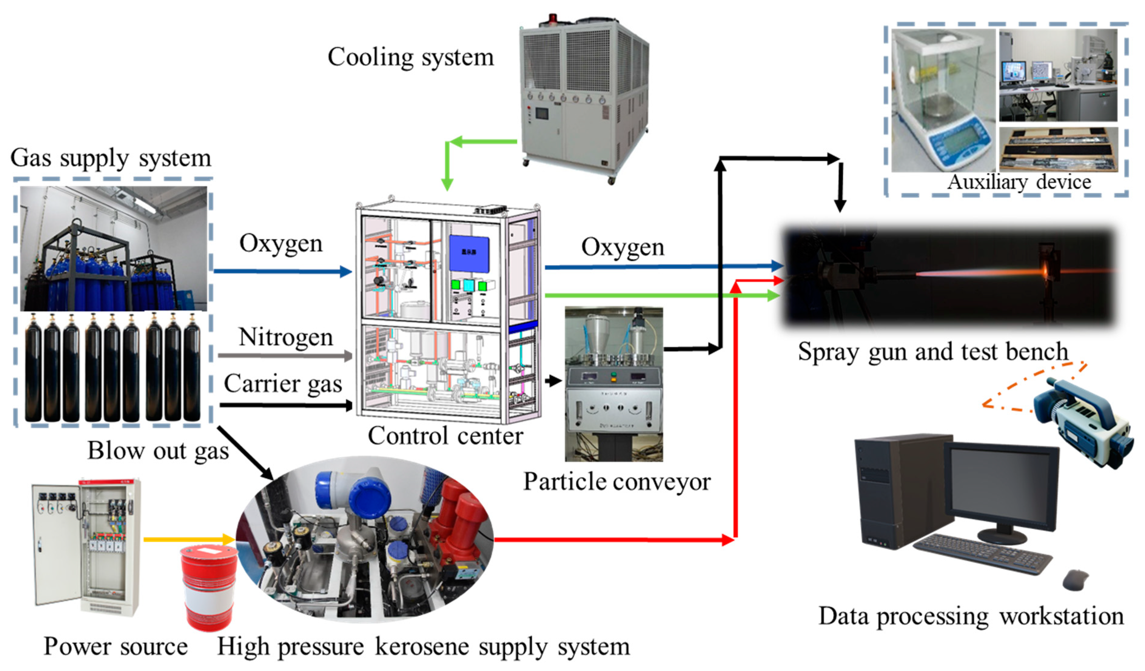
2.1. System Framework and Components

The overall composition of the innovative HVOF thermal spray system is shown in Figure 1, including kerosene, nitrogen, oxygen and cooling water supply system, as well as power supply, particle conveyor, spray gun, test bench (usually composed of manipulator and turntable) and other supporting subsystems. In addition, the legends of the important components involved in the system have been indicated, which are mainly connected through hard metal pipelines or hoses, while the electrical control lines are not marked.
The spray gun is the most important part of the HVOF system. The maximum working pressure of the combustion chamber P c was designed to be 2.0 MPa, and the rated mixture ratio was close to the chemical equivalent of 3.0. It is worth mentioning that the theoretical working parameters of the spray gun were obtained through the chemical equilibrium calculation (CEA) program originally applied to the design of the rocket engine combustion [35].
Referring to the theoretical calculation method of the combustion chamber and nozzle of the LRE [36], the main design parameters of the spray gun are shown in Table 1.
The chamber pressure and mixture ratio are the initial values for the design. Given the nozzle throat diameter D t , other parameters such as total flow rate m ˙ , combustion chamber diameter D c , specific impulse I s p and thrust F can be obtained [35]. It should be clearly noted that specific impulse and thrust are not the main parameters of the spray gun; the oxygen flow rate m o and kerosene flow rate m f are the key process parameters that can be controlled during the actual spray process.
The main structure modeling of the spray gun was completed based on 3D modeling software (Solidworks 2020), and all components were installed on the matrix of the spray gun in which the combustion chamber was connected to the gas duct through the Laval nozzle, as depicted in Figure 2. The solid particles were mixed with the axial gas after radial entering from the particle conveyor to form the high-temperature and high-velocity gas-solid two-phase flow required by the spray process. Meanwhile, the high-pressure cooling water entered from the cooling jacket on the inner side and then flowed into the external cooling jacket through certain holes in the powder transport component, as well as some small cooling holes at the end of the gas duct, and finally flowed back to the circulating cooling water tank.
The overall HVOF system was constructed through the above spray gun design and other associative components, and the main parameters of the working medium required by the system are listed in Table 2, where the SLM is the unit of gas mass flow rate per minute.

2.2. Working Process

The working process of the HVOF spray system is as follows: The cooling water system starts to work first to ensure that the spray gun has a good cooling effect when the combustion reaction occurs. Then, oxygen and kerosene are injected into the spray gun under the control of the pressure-reducing valve, the flow-regulating valve and the plunger pump and valve, respectively. In a very short time, the fuel is atomized by the gas-liquid coaxial injector, and the mixture is ignited by the spark plug to generate high-temperature and high-pressure gas, which is accelerated through the Laval nozzle to generate supersonic jet. Based on this, the powder in the particle conveyor is radially fed into the nozzle of the spray gun by the carrier gas after the gas is stabilized to form the high-temperature and high-velocity particle jet. These particles are deposited on the substrate surface when the manipulator controls the spray gun to move along the preset path and eventually form a dense coating.
At the end of the spray process, the control system will automatically execute the shutdown program. First, the kerosene is closed, and after a delay of 6 s, the oxygen is cut off while the nitrogen is blown out. At this point, the system is returned to the initial state and ready for the next spray process.

2.3. Measurement and Control Methods

The automatic spray system was controlled by a programmable logic controller (PLC, Siemens S71200, Berlin, Germany), and the human-computer interaction interface (HMI, Weinview cMT3151, Shenzhen, China) displayed the pressure of the spray gun, the mixture ratio, the pressure, the flow rate and the temperature value of each main node in real time. Because the pressure of the decompressor and the speed of the cooling water centrifugal pump are usually set as fixed values, the main parameters that could be controlled during the actual spray process were the opening of the gas valve and the frequency of the kerosene plunger pump controller.

3. The Digital Model

From the perspective of the HVOF system design and parameter selection, it was of great significance to establish a digital simulation model that could reflect the characteristics of the actual equipment so that designers or users could quickly obtain the required parameter information before operating the engineering prototype [21].
The HVOF system proposed in this paper is essentially a combination of the pressure-fed LRE and the pump-fed LRE. Therefore, the digital model of the system can be established by using the basic governing equations of the LRE similar to that in the literature [27,36,37]. The modeling method is also known as IRC method [38], as well as the centralized parameter method.

3.1. Pipeline and Valve Model

Based on the reference [35,39,40], the general dynamic models of pipelines, valves and other throttling elements of the HVOF system have been established in the thermohydraulic library and pneumatic library of the AMESim software (AMESim 2210), and the parameters have also been modified.
The basic equations of the pipeline are [39]:
d p d t = β eff [ 1 ρ d ρ d t + α d T d t ]
d T d t = d h i n + d m h i h d m i c p ρ V eff + α T c p ρ d p d t
where ρ is the density, d m i is the input mass flow rate, d m h i is the input enthalpy flow rate, β eff is the combined bulk modulus, V eff is the effective volume and d h i n is the heat exchange between the pipeline and the outside.
For the pipeline, considering the frequency response and fluid inertia, the flow derivative is expressed as:
Q t = A ρ P x g A sin ( θ ) f f Q 2 sign ( Q ) 2 D A
where A is the cross-sectional area, θ is the inclination angle and f f is the coefficient of friction.
Due to the differences in compressibility between liquid and gas, there is a large discrepancy in the representation of the high-speed flow parts such as the nozzle elements, which are described in the model of the spray gun in Section 3.4.

3.2. High-Pressure Cylinder Model

The oxygen required for the HVOF system was stored in high-pressure cylinders, whose numerical model was a fixed volume pneumatic chamber with pressure dynamics.
The temperature and pressure of the cylinder group can be calculated by the following formula [40]:
[ V ( ρ p ) T V ( ρ T ) p m ( h p ) T V m ( h T ) p ] [ d p d t d T d t ] = [ d m i d t ρ d V d t d m i d t h i h d m i d t + δ Q ]
The above model obeys the first law of thermodynamics, where the mass flow rate, enthalpy flow rate and volume change are input from the associated external model, and the density and enthalpy are obtained from the gas state equation. For high-pressure gas, the Peng-Robinson model [41] can obtain more accurate simulation results, whose equation of state is as follows:
P = r T v b a [ 1 + m ( 1 T T c ) ] 2 v 2 + 2 b v b 2
where a is the attractive term and b is the covolume, both of which depend on the critical pressure and critical temperature of the material.

3.3. Pump Model

The HVOF system contained two main pumps, one of which was a plunger pump for pressurizing kerosene and the other was a centrifugal pump for pressurizing the cooling water. The kerosene pump was a piston pump with an axial swash plate, and its numerical model was precisely established based on the thermal hydraulic library of the AMESim platform [42]. Figure 3 shows the head structure of the kerosene plunger pump in the AMESim platform, whose numerical model considers the relatively real cavity and leakage channel structure.
The volume flow rate is defined as [42]:
Q = Δ p 12 μ l c r c 3 π d p ( 1 + 3 2 ( e c c r c ) 2 ) + v + + v 2 r c π d p
where Δ p is the pressure difference, r c is the radial clearance, d p is the outer diameter of the piston, l c is the contact length, μ is the average hydrodynamic viscosity, e c c is the eccentricity of the piston and v + and v are the sleeve and piston speeds, respectively.
Considering the leakage structure of the plunger pump, the numerical model is modified as follows:
d p n i d t = β ( Q d v o l i ) ( v 0 + v o l i ) + β α d T n i d t
Q = Q nini + Q nout i + Q nlspi + Q nlpci + Q nlbpp
where v o l i is the sum of the constant volume and the variable volume of each chamber. The pressure change is determined by the total flow rate Q , which consists of the inlet flow rate Q nini , the outlet flow rate Q nout i and the external leakage flow rate Q nlspi , Q nlpci and Q nlbpp .
More generally, the average flow rate and efficiency are:
Q T h = d i s p l × ω
η v o l = Q m e a n Q T h
where the d i s p l is the theoretical displacement, and ω is the rotation speed of the plunger pump.
The speed of the motor used to drive the kerosene pump is controlled by a frequency converter, thereby regulating the flow of kerosene. In detail, the motor model with a frequency converter module built based on the electronic library and signal library of the AMESim platform is described in Figure 4. The three squirrel-cage motor models are controlled by frequency signal (B3), whose output is the speed and torque matching the load of the pump head.
The winding connection of the machine is a star connection, and the frequency converter is a variable frequency sine wave model [43]:
U = U 0 + a sin ( 2 π 360 ( θ + φ ) )
In addition, the squirrel-cage induction motor is used as the driving source, and its electromagnetic torque is as follows:
Γ = p ( 1 σ ) L s ( I r d m I s q I r q m I s d )
where p is the power of motor; L s is the stator cyclic inductance; σ is the dispersion coefficient; and I r d m , I s q , I r q m and I s d are modified rotor currents in an orthonormal linear algebra transformation with power conservation. The basic equations of each phase of the motor obey the generalized Ohm’s law, and the specific derivation is given in reference [43].
Furthermore, the coolant pump is a centrifugal Suter pump [34], and the behavior during a transient event can be described by reference parameters, Suter head table and Suter torque table. The pump head H is:
H = H R W H ( α 2 + ν 2 )
where H R is the reference head, W H is the head function and α and ν are dimensional variables.
The pump torque is:
T = ( α 2 + ν 2 ) W T T R
where T R is the reference head and W T is the head function.
The derivative of the volumetric flow rate is:
d Q d t = ρ g H ( P 1 P 3 ) I
where I is the fluid inertia, and the pressure difference can be set as d P = P 1 P 3 ; meanwhile, d H = d P / ( g ρ ) . The above equations can be solved iteratively to obtain the final head, flow and torque parameters of the centrifugal pump.

3.4. Spary Gun Model

The spray gun consists of the fuel injector, combustion chamber, Laval nozzle, gas duct and cooling jacket. Wherein, the injector is actually a small nozzle, and the mass flow rate m ˙ for a liquid injector is [40]:
m ˙ = ρ c q A 2 | Δ P | ρ
where c q is the flow coefficient, and A is the cross-sectional area.
For a gas injector, the mass flow rate is:
m ˙ = C q A Ψ 2 P u p ρ u p k d p
where Ψ is the flow function and k d p is the pressure loss coefficient. When the injector is not clogged, Equation (17) is the same as Equation (16). Otherwise, Ψ is related to the pressure ratio:
Ψ = { 1 1 γ s η 2 γ s η 1 + γ s η > η c r γ s 1 + γ s ( 2 γ s γ s + 1 ) γ s 1 γ s η η c r
In the one-dimensional compressible flow, γ s is the isentropic calorific factor, η is the current pressure ratio and η c r is the critical pressure ratio.
In addition, the combustion chamber of the spray gun is a combination of a mixed gas chamber and a nozzle. A zero-dimensional premixed combustion model [27] was applied to simulate the low-frequency dynamic characteristics of the combustion chamber. Based on the assumptions of adiabatic, uniform and pure gas phase condition, the model of the combustion chamber is a super component composed of signal library components on the AMESim platform, and its pressure was calculated by the temperature, composition and physical parameters of the gas mixture, as illustrated in Figure 5. The governing equations of the mixed gas in the combustion chamber are shown in Equations (19) and (20), which require several iterations to solve [27].
d m c d t = m ˙ o ( t τ ) + m ˙ f ( t τ ) m ˙ o u t
d ρ d t = 1 V c d m c d t
where τ is the time delay parameter and V c is the volume.
The mixture ratio in the combustion chamber can be quickly solved by the super component [44]. According to thermodynamic calculations, there are 10 main materials in the combustion reaction, such as OH, CO2, H2O, etc. Based on the CEA batch calculation program, multidimensional thermodynamic data tables are generated, and these data tables are interpolated from 0 to 7 MPa for pressure and 0 to 500 for the mixture ratio. Then, the combustion components and gas temperature are obtained by interpolation, and the pressure of the combustion chamber is finally calculated, which will be used in the next iteration calculation.
As a result, the mass fraction of each component and the temperature of the mixture are as follows [45]:
Y i = Y i ( K , P c )
T = T ( K , P c )
The time derivatives of mass fractions are:
d Y i d t = 1 m ( d m i d t Y i d m d t )
The mass balance considering partial derivatives with respect to pressure, density and mass fractions is:
V ρ P | T , Y j d P d t + V ρ T | P , Y j d T d t = j m ˙ [ j ] ρ d V d t V i ρ Y i | P , T , Y j i d Y i d t
The energy balance considering partial derivatives with respect to pressure, density and mass fractions is:
( m h P | T , Y j V ) d P d t + m h T | P , Y j d T d t = j m ˙ [ j ] h [ j ] h j m ˙ [ j ] + δ Q ˙ m i h Y i | P , T , Y j i d Y i d t
Moreover, the interaction mechanism between temperature and pressure in the combustion chamber is illustrated in Figure 5. The curved surface on the right represents the theoretical combustion temperature of the combustion chamber at different mixture ratios and pressures. It can be seen that the temperature varies greatly when the mixture ratio is between one and three and also increases slightly with the increase of pressure, but it is obvious that the mixture ratio is the main reason for the change of temperature.
The chemical energy is converted into mechanical energy when the combustion product passes through the nozzle, which produces the high-temperature and high-speed gas required for the spray process. As a downstream component of the combustion chamber, the nozzle determines the mass of the gas flowing out of the upstream combustion chamber. The flow rate of the nozzle is calculated according to Equation (17).
For the cooling jacket, the heat exchange pipeline in the thermohydraulic library and the metal mass block in the mechanical library of AMESim platform are used to simulate the components involved in the heat exchange calculation, as shown in Figure 6, and the heat transfer model is divided into six centralized parameter nodes. The numerical model of the heat exchange on the gas side is the Bartz method [37], and the heat exchange between the wall and the coolant is calculated by the model in reference [39]. The governing equation for fin conduction is [33]:
d h = λ   A ( T 2 T 1 )
where d h is the heat flux, λ 1 is the thermal conductance, A is the heat exchange area and T is the temperature of the corresponding node.

3.5. Digital Model of the System

Based on the modular modeling theory, a dynamic simulation model of the HVOF system was established on the AMESim platform, as shown in Figure 7. The spray operation program is controlled by the signal element, and the whole model contains 135 dynamic equations. The purpose of the system compilation is to transform the power bond graph into state-space equations, which can be solved by numerical calculation methods (the Runge-Kutta method or the Linear Multistep methods) [46]. Finally, the digital model of the system was solved by the variable step size solver. The solver can automatically select the best integration algorithm according to the mathematical characteristics of the model and dynamically switch the integration algorithm and adjust the integration step size, which greatly improves solution efficiency.
The digital model of the innovative HVOF system can be used in two ways: one way is to directly obtain the dynamic characteristics of each component of the spray system by the given flow rate of working medium. The second way is to use the optimization algorithm represented by the NLPQL algorithm or genetic algorithm (GA) for reverse iterative calculation when the requirement parameters (temperature and pressure) are clearly proposed, thus the control parameters required by the actual spray process (working fluid flow) can be quickly obtained, which is exactly the advantage of the scheme design based on the digital model [47].

4. Experiment

4.1. Material Preparation and Spray Process

The spherical, agglomerated and sintered WC-12 wt.%Co powder was obtained from Sulzer Metco WOKA GmbH (Woka-3102), Thuringia, Germany. The scanning electron microscope (SEM) in Figure 8a shows that these particles were regular spheres with a distribution range of 15~45 μm.
The detailed spray process is as follows: First, the 45# steel substrate was cleaned by ultrasonic with acetone and alcohol, respectively, in order to fully remove the oil stain on the surface. The substrate was then sandblasted by 250 μm brown corundum (Al2O3), where the sandblasting distance and pressure were set to 80 mm and 0.45 MPa, respectively. After that, the specimen was installed in the fixture placed on the turntable, and the self-developed HVOF equipment was started to carry out the spray experiment according to the preset route. The moving track of the spray gun is depicted in Figure 8b with horizontal and vertical moving speeds of 200 mm/s, and distances of 250 mm and 5 mm, respectively. Thus, the spray gun and the manipulator were linked together to complete a complete spray process.

4.2. Experiment Scheme Design Method

As a kind of thermodynamic mechanical equipment, the state change of the combustion chamber of the spray gun has the most direct influence on the spray effect. In other words, the pressure and temperature of the combustion chamber are the most representative and decisive parameters for the design of the spray scheme. However, the working parameters are usually given empirically in most traditional studies, which makes it difficult to be directly referred to by others due to differences in equipment and environment. Considering this deficiency, an efficient experiment scheme design method based on the digital model of the HVOF spray system is innovatively proposed, as shown in Figure 9.
The temperature and pressure target values of the combustion chamber were firs derived according to the given reference values, and then the optimization algorithm in the digital model of the system was adopted to solve the numerical equations in reverse, so as to obtain the theoretical values of the oxygen, the kerosene flow rate or the mixture ratio, which can be input as direct control parameters into the actual spray process. After that, the spray experiment marked on the right of the figure can be carried out fully automatically. According to the output data of the system sensor and the coating performance, it can be determined whether the model and sensors need to be calibrated or the control parameters used in the spray process should be modified. It can be concluded that the design method based on the digital model has important practical application value for rapidly iterating process parameters and adaptation to various types of spray environment.

4.3. Characterization and Measurement

The self-developed HVOF spray system is shown in Figure 10 and is connected by pipelines and cables. All components, including the manipulator, are operated remotely by the control center, and the precise control of the working mediums, such as kerosene and oxygen, is achieved through the PLC and HMI embedded with the PID control algorithm. Temperature sensors (Meacon PT100, Hangzhou, China), pressure sensors (Microsensor MPM270, Baoji, China), gas flow meters (Seven Star D07, Beijing, China) and kerosene flow meters (Krohne Opimass 3400-S03, Duisburg, Germany) were deployed to achieve real-time recording and the display of the parameters in the system. A camera (Canon EOS 70D, Ota Ward, Tokyo, Japan) was used to record the spray process.
The micromorphology of the coating surface and bonding interface was characterized by the scanning electron microscope (SEM, FEI Quanta 200feg, Hillsboro, OR, USA). The microhardness of the coating was measured by the Vickers Microhardness tester (Buehler Omnimet MHT, Lake Bluff, IL, USA) under an indent load of 300 gf with a dwelling time of 15 s (20 indents for each specimen). The wear performance of the coating was tested on the ball-on-disk tribometer (Rtec, MFT-5000, San Jose, CA, USA), and the volume wear rate was measured by a three-dimensional white light interferometer instrument (Zygo, NexView, Middlefield, CT, USA).

5. Results and Discussion

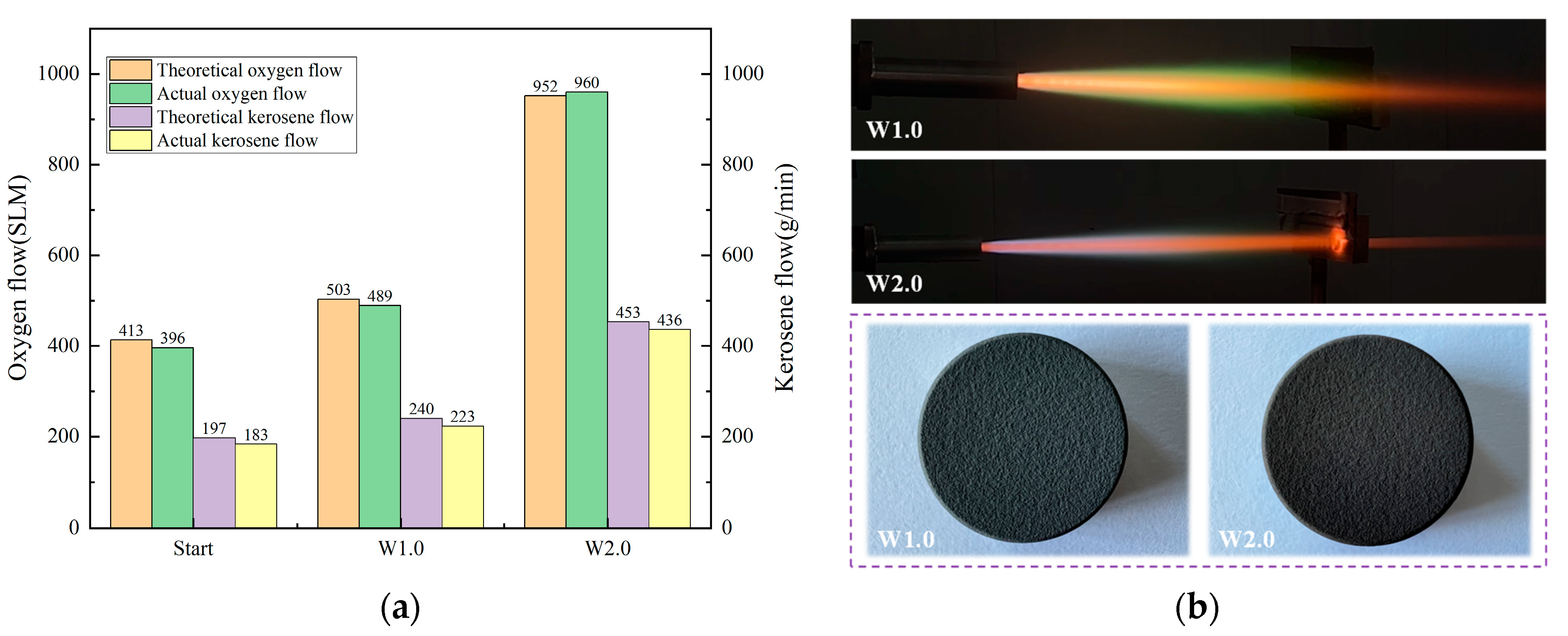
5.1. Typical Working Parameters of the Spray Process

According to the design method proposed in Section 4.2, two pressure conditions of 1.0 MPa and 2.0 MPa in the combustion chamber were simulated in the digital model of the system, which are marked as W1.0 and W2.0, respectively. The specific solution process is as follows: with the combustion chamber pressure and temperature as the target values, the NLPQL optimization algorithm mentioned in Section 3.5 was used to reverse-solve the digital model of the HVOF system. The iterative calculation steps of the program were fewer than seven steps, and the corresponding control parameters of the working medium were output. Figure 11a shows the comparison between the theoretical and experimental values of typical control parameters under the conditions of 0.8 MPa at the initial ignition and 1.0 MPa and 2.0 MPa in the spray process. Based on the simulation results, the experimental values were obtained in the actual spray system with the combustion chamber pressure as the target value. As depicted in Figure 11a, the simulation results are very close to the experimental results, with the errors of kerosene flow rate and oxygen flow rate being less than 4% and 7%, respectively. It is worth mentioning that the error of oxygen flow rate was only 3.7% at 2.0 MPa. Therefore, it is can be preliminarily inferred that the digital model of the system has high accuracy in the design of the experiment scheme. Meanwhile, the results in the figure also reflect the fact that the increase of combustion chamber pressure requires the increase of the kerosene and oxygen flow rate. In other words, when the combustor pressure increases twice, the corresponding working medium actually needs to increase by about 1.96 times. The main reasons for the slight difference between the theoretical and experimental flow rates are that the simulation model underestimates the actual combustion efficiency of the combustion chamber, and that there is the error of the throat diameter data of the Laval nozzle used in the model and the actual processing size to consider.
Based on the preliminary test results obtained in the digital model, the key parameters in the actual spray experiment are shown in the Table 3. The spray process of the WC-12Co powder on the surface of the 45# steel circular specimen with a diameter of 50 mm is depicted in Figure 11b, in which the dense and uniform coatings are deposited on the surface of the two substrates. However, the flame length of the W2.0 is significantly longer than that of the W1.0, which is due to the increase of the gas flow rate at W2.0 and the increase of velocity and temperature of the WC-12Co particles at the higher chamber pressure.

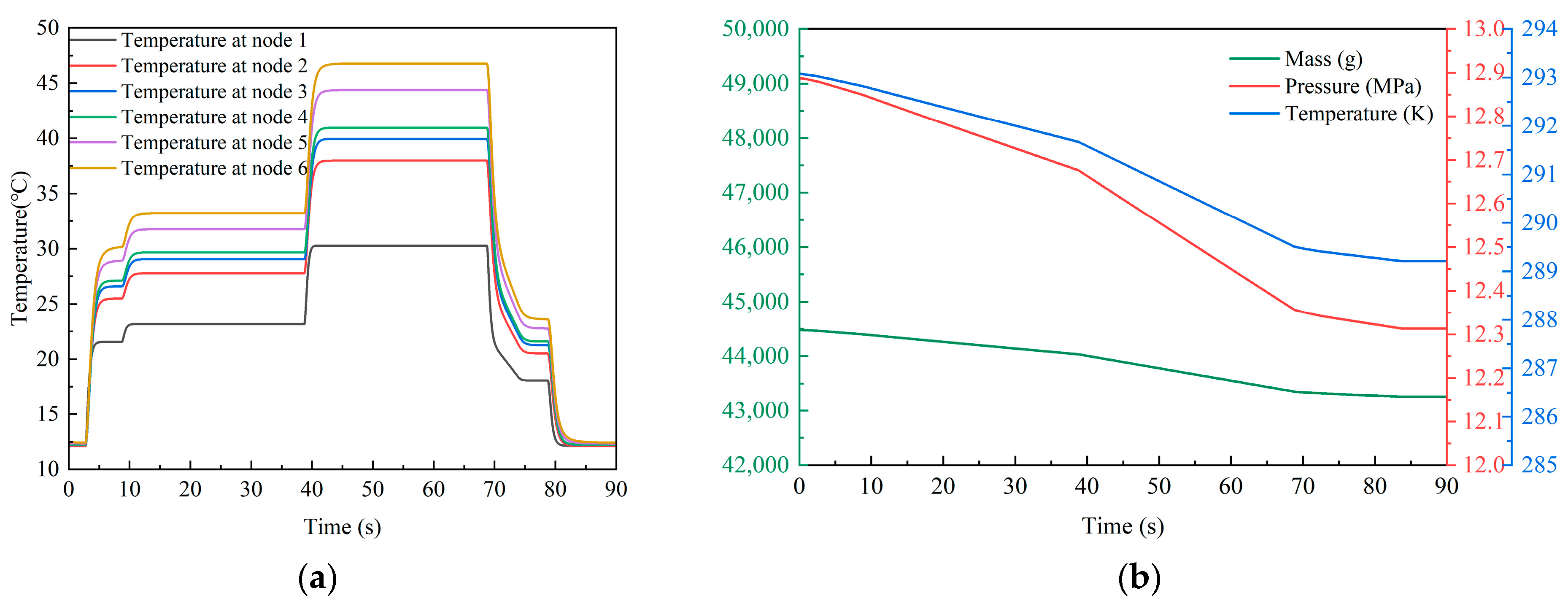
5.2. The Adjustment Process of the System Working Conditions

Taking the control parameters designed in Section 5.1 as input, the whole spray process of the system from start-up to continuous adjustment until shutdown can be easily simulated by the digital model.
Figure 12a shows the whole process of the pressure, temperature and flow rate of the combustion chamber in the spray gun changing with the control instruction under the two working conditions of the W1.0 and W2.0 for 30 s. At a pressure of 1.0 MPa, the oxygen flow rate is 11.99 g/s (the actual value is 11.65 g/s), and the kerosene flow rate is 4.00 g/s (the actual value is 3.72 g/s); meanwhile, the temperature of the combustion chamber is 3380 k. When the pressure is set at 2.0 MPa, the oxygen flow rate is 22.66 g/s (the actual value is 22.86 g/s), and the kerosene flow rate is 7.55 g/s (the actual value is 7.27 g/s) with the temperature of 3472 K. When the mixture ratio remains unchanged, the temperature in the combustion chamber will increase slightly at higher working conditions (about 90 K), which is consistent with the physical mechanism of the high-pressure combustion described in Equation (25). The results show that the flow rate target value in the dynamic process is the same as the static value obtained by reverse calculation in Section 5.1, which reconfirms the repeatability of the simulation model. In addition, the dynamic simulation results also demonstrate that the response speed of the system is fast, and the simulation design is in agreement with the experimental results.
The changes of the pressure, temperature and flow rate parameters in the combustion chamber during the start-up stage are shown in Figure 12b, where the step signal is the target flow rate value of the oxygen and kerosene output by the control system. At the initial moment, oxygen enters the spray gun at a rate of 5.53 g/s. After 0.7 s, the kerosene supply command is issued, and it increases synchronously with the oxygen flow rate within the following 3 s. The adjusted target values are 9.84 g/s and 3.28 g/s, respectively. Because the pipeline of the kerosene system is initially empty, its filling is completed in about 2 s, after which the kerosene is injected into the combustion chamber, thus completing the ignition process. At this moment, the pressure of the combustion chamber rises suddenly, and the flow rate of oxygen and kerosene decreases temporarily under the action of the back pressure, which is consistent with the physical mechanism of the pipeline pressure difference and flow rate in Equation (3). Then, under the influence of the PID controller, the system is quickly and automatically adjusted to the design start condition of the spray gun (0.8 MPa) within 1.7 s. The ignition response lag time of the spray process is about 0.7 s, which verifies the fast response speed of the system ignition.
Figure 12c depicts the changes of pressure, temperature and flow rate parameters in the combustion chamber during the adjustment process. The step control signals of the target flow rate of oxygen and kerosene increase from 11.99 g/s and 4.00 g/s to 22.66 g/s and 7.55 g/s, respectively. When the pressure of the combustion chamber increases from 1.0 MPa to 2.0 MPa, the temperature fluctuates from 3380 K to 3472 K, which is the result of the joint influence of Equations (3), (16), (24) and (25). Compared with the 0.7 s response time of system ignition, the lag time of system response is about 1.3 s due to the greater range adjustment of working conditions in Figure 12c.
The control parameters change of the kerosene pump in the whole process is analyzed in Figure 12d. At the start-up and at the two working conditions of W1.0 and W2.0, the frequencies of the frequency converter are 7.54 Hz, 9.22 Hz and 17.58 Hz, and the rotation speeds of the kerosene pump are 226 rpm, 276 rpm and 528 rpm, which are consistent with the dynamic process trend of the system in Figure 12a. The results show that the system has a great control effect on the whole change process of the kerosene flow rate.
Figure 12e shows the change of the control parameters of the kerosene pump during the start-up process. At the initial stage, due to the filling process of the kerosene pipeline, the measured value of the kerosene flow rate responds slowly, and the signal of the frequency converter is close to 40 Hz, resulting in the rotation speed of the pump reaching a peak of 1300 rpm around 2 s, which is obviously an overshoot phenomenon. The phenomenon is the interaction result between the motor torque relation in Equation (12) and the PID closed-loop control loop described in Figure 7. Due to the fast response speed of the motor components in the spray system, the motor torque increases rapidly when the frequency converter signal is amplified. Whereas in the following 0.7 s, the control frequency of the frequency converter returns to the target design value, which can realize the stable control of the kerosene flow rate.
Furthermore, the change of the control parameters of the kerosene pump during the shutdown stage is exhibited in Figure 12f. At the moment of 68.7 s, the step control signal first returns the working condition of the W2.0 to the state of the start-up stage, corresponding to the combustion chamber pressure of 0.8 MPa. After that, the working condition is gradually adjusted to the shutdown stage with the flow rate as low as 1.85 g/s, at which time the corresponding pressure of the combustion chamber is 0.4 MPa. The decline process continues for about 5 s due to the design of the control instruction timing in Figure 12a, which can reduce the impact of a sudden shutdown at high working conditions. It is worth noting that, due to the inertia of the system, the step control signal has a response lag time of 0.7 s. In addition, it can be observed from the curve in the enlarged figure that there are inherent parameter fluctuations in the working process of the plunger pump, reflecting the reciprocal relationship between the pump flow rate and the plunger presented in the Equation (6). In order to achieve the relatively stable flow rate control, the control signal of the frequency converter also has a correspondingly small vibration amplitude under the inherent fluctuation characteristic.
Figure 13a shows the water temperature changes of the six nodes of the spray gun cooling jacket during the whole process. The temperature of the cooling water flowing through each node gradually rises, and the higher the working condition, the higher the temperature, which is consistent with the results predicted by the spray gun heat transfer model of Equation (26) in Section 3.4. Due to the adoption of circulating refrigeration, the inlet water temperature is maintained at 12 °C. When the working condition is W1.0, the outlet temperature of the spray gun is 33.24 °C, which rises to 46.78 °C at the W2.0. During the actual spray process, the HMI shows that the measured water temperature is 35 °C and 48 °C, respectively, which is very consistent with the simulation results.
The variation trend of the parameters of the oxygen cylinder group during the spray process is analyzed in Figure 13b. It can be seen that in the continuous spray process of 90 s, the pressure of the oxygen cylinder gradually decreases by 0.58 MPa, and the mass of the gas is reduced by 1223 g. Additionally, due to the expansion cooling mechanism revealed by the high-pressure gas state equations in Equations (4) and (5), the temperature of the oxygen cylinder decreases about 3.87 K, which is consistent with the actual process. The simulation results show clearly the mass reduction of the oxygen cylinder, which is conducive to accurately evaluating the gas consumption and formulating a reasonable oxygen combination and replacement plan for long-term spray experiments under high working conditions.

5.3. Characterization and Analysis of the Coatings

Figure 14 shows the deposited coatings’ surface morphology when the pressures of the combustion chamber are 1.0 MPa and 2.0 MPa, respectively. The surface of the coating obtained under the working condition of W1.0 presents obvious unevenness, with large fluctuations and more ridges, as shown by the orange arrow in the Figure 14a. On the contrary, the surface of the coating prepared at 2.0 MPa is relatively flat (Figure 14b). Moreover, it can be seen from the red line area of the enlarged Figure 14c,d that the WC-12Co particles become more cohesive under the working condition of W2.0 than that of W1.0, which is beneficial for facilitating the effective bonding of the coating and substrate and the bonding between the coatings.
Figure 15 shows the comparison of the cross-section morphology of the two coatings. The combination of the two coatings and substrates is good (Figure 15a,d), but the difference is that there are obvious microcracks (shown by the red dashed line in Figure 15b and more pores (shown by the yellow arrow in Figure 15c) in the cross-section of the coating prepared under the W1.0. It is obvious that when the pressure increases to 2.0 MPa, the coating becomes denser and the pores are significantly reduced (Figure 15e,f). Moreover, the edges of WC-12Co particles become rounded and the melting degree increases, as shown by the orange dotted circle in Figure 15f, which indicate that the increase of the pressure is conducive to the further softening of particles, thus strengthening the bonding of the coating.
The wear resistance of the two coatings is tested on the ball-on-disk tribometer with Al2O3 ball (radius, 9.525 mm) as a counter grinding ball, and the results are analyzed in Figure 16. Prior to the test, it is necessary to mechanically polish the surface of the coating to a mirror finish (Ra < 0.27 μm) according to ASTM G99-05 Standard [48]. The specific polishing process is as follows: the specimens are continuously ground with 80–1500 mesh SiC abrasive papers, after which they are polished by 1 μm diamond pastes and finally degreased with acetone in an ultrasonic bath and dried in warm air. Furthermore, the parameters used in the wear test are kept constant, including the normal load of 100 N, the sliding speed of 200 rpm, the sliding time of 60 min, and the radius of a wear track of 10 mm.
The friction coefficients of the two coatings are very similar (Figure 16a), but the volume wear rate under the W2.0 is 1.48 × 10⁻⁵ mm3/Nm, which is lower than that of the W1.0 (1.81 × 10⁻⁵ mm3/Nm), as shown in the yellow column of Figure 16b. At the same time, the hardness of the two coatings is compared (as shown in the green column of Figure 16b), and it was found that the hardness value under the working condition of W2.0 is 1445.685 Hv, while the hardness value of the W1.0 is only 1172.597 Hv. It was concluded that the difference in the hardness of the coating is likely to affect its wear degree. In addition, the three-dimensional morphology of the two coatings and the grinding ball is shown in Figure 16c,d by the three-dimensional white light interferometer instrument testing. It can also be seen that the wear track under the working condition of W1.0 is wider than that of the W2.0, and the corresponding worn diameters of the grinding balls are 3028.499 μm and 2234.980 μm, respectively. The results demonstrate that the wear resistance of the coatings prepared under different pressures is obviously different, that is, the increase of the pressure of the combustion chamber is conducive to improving the wear resistance of the coatings.

6. Conclusions

In order to further optimize and improve the traditional thermal spray process, an innovative HVOF thermal spray system based on the digital model was established, and an engineering prototype was developed to carry out validation experiments. The main conclusions are as follows:
(1)
An efficient design method based on the digital model designed by the AMESim multidisciplinary simulation platform of oxygen/kerosene high-pressure HVOF spray system was proposed for the first time. The dynamic characteristics of key components such as a combustion chamber, a kerosene pump, a cooling jacket and an oxygen cylinder group were obtained by calculating the two process parameters under the pressures of 1.0 MPa and 2.0 MPa, respectively. The simulation results show that the dynamic response time of the system was less than 0.7 s although the duration was 1.3 s when the working medium changed from W1.0 to W2.0. Meanwhile, the error between the simulation and experiment results was generally less than 5%, which proves the accuracy of the digital model and the efficiency of the design method.
(2)
The microstructure and mechanical properties of WC-12Co coatings deposited at pressures of 1.0 MPa and 2.0 MPa demonstrate that the innovative high-pressure HVOF spray technology is extremely feasible and efficient in the preparation of denser cemented carbide coatings. The microhardness of the coatings deposited at the working condition of W2.0 is 1446 Hv, which is about 23% higher than at W1.0 (1173 Hv). The corresponding volume wear rate was reduced from 1.81 × 10⁻⁵ mm3/Nm to 1.48 × 10⁻⁵ mm3/Nm by about 18%. Therefore, it was demonstrated that the increase of the pressure of the combustion chamber in the spray gun is beneficial for enhancing the density and wear resistance of the coating so as to improve the actual performance of the coating.
(3)
The accuracy of the system model and the advantages of the innovative high-pressure HVOF spray technology based on the digital model were thoroughly verified by the actual experiments, which indicates that the design method has important theoretical value and application significance for exploring the spray process parameters and predicting the spraying effect under higher working conditions.

Author Contributions

Conceptualization, M.Y. and B.Z.; methodology, M.Y.; software, Q.S.; validation, G.Z.; formal analysis, Q.S.; investigation, M.Y.; resources, X.Y. and Z.S.; data curation, M.Y. and Q.S.; writing—original draft preparation, M.Y.; writing—review and editing, M.Y. and Q.S.; visualization, M.Y.; supervision, B.Z.; project administration, X.Y.; funding acquisition, Z.S. and B.Z. All authors have read and agreed to the published version of the manuscript.

Funding

Please add: This research was funded by the Natural Science Basic Research Program of Shaanxi Province (No. 2021JM-250) and the National Natural Science Foundation of China (No. 52375559).

Data Availability Statement

Data are contained within the article.

Acknowledgments

The characterization and analysis of coating properties are supported by the State Key Laboratory of Tribology in Advanced Equipment, Tsinghua University.

Conflicts of Interest

The authors declare no conflicts of interest.

Nomenclature

P c chamber pressure (MPa) Q total flow rate (m3/s)
Tideal temperature (K) Q nini inlet flow rate (m3/s)
C*characteristic velocity (m/s) Q nout i outlet flow rate (m3/s)
ε expansion ratio Q nlspi the piston-cylinder leakage flow rate (m3/s)
m ˙ total flow rate (g/s) Q nlpci the slipper-swash plate leakage flow rate (m3/s)
μ mixture ratio Q nlbpp the barrel-port plate leakage flow rate (m3/s)
m o gas oxygen flow rate (g/s) d i s p l theoretical displacement (m3/rad)
m f kerosene flow rate (g/s) ω rotation speed of the plunger pump (rad/s)
D t throat diameter (mm) U voltage (V)
D e exit diameter (mm) L s stator cyclic inductance (H)
D c chamber diameter (mm) p power of motor (W)
L c chamber length (mm) σ dispersion coefficient
I s p specific impulse (m/s) I r d m modified rotor current (A)
F ideal thrust (N) H pump head (m)
ρ density (kg/m3) H R reference head (m)
d m i input mass flow rate (kg/s) W H head function
d m h i input enthalpy flow rate (W) α adimensional variables
β eff combined bulk modulus (Pa) ν adimensional variables
V eff effective volume (m3) T R reference torque (Nm)
d h i n heat exchange (W) W T head function
A cross-sectional area ( m 2 ) I fluid inertia ( kg / m 4 )
θ inclination angle (°) c q flow coefficient
f f coefficient of friction Ψ flow function
a attractive term k d p pressure loss coefficient
b covolume γ s isentropic calorific factor
δ Q heat flow provided to or exiting from the control volume (W) η current pressure ratio
Δ p pressure difference (Pa) η c r critical pressure ratio
r c radial clearance (m) τ time delay parameter (s)
d p outer diameter of the piston (m) V c volume (m3)
l c contact length (m) Y i mass fraction of each component
μ average hydrodynamic viscosity (kg/m/s) K mixture ratio in digital model
e c c eccentricity of the piston T temperature of the mixture
v + sleeve speed (m/s) d h heat flux (W)
v piston speed (m/s) λ thermal conductance ( W / m 2 / K )
v o l i the sum of the constant volume and the variable volume of each chamber (m3) A heat exchange area ( m 2 )

References

  1. Mittal, G.; Paul, S. Suspension and solution precursor plasma and HVOF spray: A review. J. Therm. Spray Technol. 2022, 31, 1443–1475. [Google Scholar] [CrossRef]
  2. Pawlowski, L. The Science and Engineering of Thermal Spray Coatings, 2nd ed.; John Wiley & Sons, Ltd.: Hoboken, NJ, USA, 2008. [Google Scholar]
  3. Matthews, S.; James, B. Review of thermal spray coating applications in steel industry: Part 1-hardware in steel making to the continuous annealing process. J. Therm. Spray Technol. 2010, 19, 1267–1276. [Google Scholar] [CrossRef]
  4. Aranke, O.; Algenaid, W.; Awe, S.; Joshi, S. Coatings for automotive gray cast iron brake discs: A review. Coatings 2019, 9, 552. [Google Scholar] [CrossRef]
  5. Varis, T.; Suhonen, T.; Jokipii, M.; Vuoristo, P. Influence of powder properties on residual stresses formed in high-pressure liquid fuel HVOF sprayed WC-CoCr coatings. Surf Coat Tech. 2020, 388, 125604. [Google Scholar] [CrossRef]
  6. Wang, H.; Qiu, Q.; Gee, M.; Hou, C.; Liu, X.; Song, X. Wear resistance enhancement of HVOF-sprayed WC-Co coating by complete densification of starting powder. Mater Design 2020, 191, 108586. [Google Scholar] [CrossRef]
  7. Gong, T.; Yao, P.; Zuo, X.; Zhang, Z.; Xiao, Y.; Zhao, L.; Zhou, H.; Deng, M.; Wang, Q.; Zhong, A. Influence of WC carbide particle size on the microstructure and abrasive wear behavior of WC–10Co–4Cr coatings for aircraft landing gear. Wear 2016, 362, 135–145. [Google Scholar] [CrossRef]
  8. Khuengpukheiw, R.; Saikaew, C.; Wisitsoraat, A. Wear resistance of HVOF sprayed NiSiCrFeB, WC-Co/NiSiCrFeB, WC-Co, and WC-Cr3C2-Ni rice harvesting blades. Mater. Test. 2021, 63, 62–72. [Google Scholar] [CrossRef]
  9. Zhang, F.; Tabecki, A.; Bennett, M.; Begg, H.; Lionetti, S.; Paul, S. Feasibility study of high-velocity oxy-fuel (HVOF) sprayed cermet and alloy coatings for geothermal applications. J. Therm Spray Techn. 2023, 32, 339–351. [Google Scholar] [CrossRef]
  10. Anusha, K.; Routara, B.; Guha, S. A review on high-velocity oxy-fuel (HVOF) coating technique. J. Inst. Eng. India Ser. D 2023, 104, 831–848. [Google Scholar] [CrossRef]
  11. Teles, D.; de Castro, V.; dos Reis Tagliari, M.; de Souza, A.; de Fraga Malfatti, C. Effect of HVOF spray coating on the tribological surface of onshore gate valves. Wear 2024, 546–547, 205322. [Google Scholar] [CrossRef]
  12. Liu, S.; Wu, H.; Xie, S.; Planche, M.; Rivolet, D.; Moliere, M.; Liao, H. Novel liquid fuel HVOF torches fueled with ethanol: Relationships between in-flight particle characteristics and properties of WC-10Co-4Cr coatings. Surf. Coat. Tech. 2021, 408, 126805. [Google Scholar] [CrossRef]
  13. Żórawski, W. The microstructure and tribological properties of liquid-fuel HVOF sprayed nanostructured WC–12Co coatings. Surf. Coat. Tech. 2013, 220, 276–281. [Google Scholar] [CrossRef]
  14. Li, C.; Yang, H.; Li, H. Effect of gas conditions on HVOF flame and properties of WC-Co coatings. Mater. Manuf. Process 1999, 14, 383–395. [Google Scholar] [CrossRef]
  15. Li, C.; Ohmori, A.; Harada, Y. Effect of powder structure on the structure of thermally sprayed WC-Co coatings. J. Mater. Sci. 1996, 31, 785–794. [Google Scholar] [CrossRef]
  16. Sun, B.; Fukanuma, H. Deposition of WC-Co coatings by a novel high pressure HVOF. J. Therm. Spray. Techn. 2013, 22, 263–271. [Google Scholar] [CrossRef]
  17. Gerner, D.; Azarmi, F.; McDonnell, M.; Okeke, U. Application of machine learning for optimization of HVOF process parameters. J. Therm Spray Techn. 2023, 1–11. [Google Scholar] [CrossRef]
  18. Kanno, A.; Takagi, K.; Arai, M. Influence of chemical composition, grain size, and spray condition on cavitation erosion resistance of high-velocity oxygen fuel thermal-sprayed WC cermet coatings. Sur. Coat. Tech. 2020, 394, 125881. [Google Scholar] [CrossRef]
  19. Wang, H.; Wu, Y.; Cheng, J.; Zhu, S.; Cao, M.; Hong, S. Effect of binder phases on the cavitation erosion behavior of HVOF sprayed WC-based coatings. Surf. Coat. Tech. 2023, 472, 129887. [Google Scholar] [CrossRef]
  20. Lu, Y.; Liu, C.; Kevin, I.; Huang, H.; Xu, X. Digital Twin-driven smart manufacturing: Connotation, reference model, applications and research issues. Robot. Comput.-Int. Manuf. 2020, 61, 101837. [Google Scholar] [CrossRef]
  21. Ren, J.; Zhou, T.; Rong, Y.; Ma, Y.; Ahmad, R. Feature-based modeling for industrial processes in the context of digital twins: A case study of HVOF process. Adv. Eng. Inform. 2022, 51, 101486. [Google Scholar] [CrossRef]
  22. Li, M.; Christofides, P. Multi-scale modeling and analysis of an industrial HVOF thermal spray process. Chem. Eng. Sci. 2005, 60, 3649–3669. [Google Scholar] [CrossRef]
  23. Zhao, X.; Li, C.; Li, S.; Jiang, H.; Han, X. Time-varying evolutionary mechanism analysis of the multiphase flow during high-velocity oxygen-fuel (HVOF) thermal spraying WC-12Co particle. Surf. Coat. Tech. 2023, 461, 129435. [Google Scholar] [CrossRef]
  24. Li, W.; Yin, S.; Wang, X. Numerical investigations of the effect of oblique impact on particle deformation in cold spraying by the SPH method. Appl. Surf. Sci. 2010, 256, 3725–3734. [Google Scholar] [CrossRef]
  25. Gnanasekaran, B.; Liu, G.; Fu, Y.; Wang, G.; Niu, W.; Lin, T. A Smoothed Particle Hydrodynamics (SPH) procedure for simulating cold spray process-A study using particles. Surf. Coat. Tech. 2019, 377, 124812–124853. [Google Scholar] [CrossRef]
  26. Yang, M.; Song, P.; Kong, D.; Huang, T.; Jin, Q. Wear and corrosion properties of HVOF sprayed WC-Cr3C2 composite coating for application in polysilicon cyclone separator. J. Mater. Res. Technol. 2024, 29, 78–89. [Google Scholar] [CrossRef]
  27. Cao, T. Rocket Engine Dynamics; National University of Defense Technology Press: Changsha, China, 2004. [Google Scholar]
  28. Meyer, C.; Maul, W. The application of neural networks to the SSME startup transient. In Proceedings of the 27th Joint Propulsion Conference, Sacramento, CA, USA, 24–26 June 1991; p. 2530. [Google Scholar] [CrossRef]
  29. Jimenez, M.; Pluchart, S.; Mouvand, S.; Broca, O. Rocket engine digital twin–modeling and simulation benefits. In AIAA Propulsion and Energy 2019 Forum; American Institute of Aeronautics and Astronautics: Reston, VA, USA, 2019; p. 4114. [Google Scholar] [CrossRef]
  30. Pan, H.; Zhang, L. Application of AMESim software in dynamic simulation of liquid rocket engine system. Rocket Propuls. 2011, 037, 6–11. [Google Scholar] [CrossRef]
  31. Chen, H.; Liu, H.; Chen, J. Forced start process of supplementary combustion cycle engine. J. Aerosp. Power 2015, 30, 3010–3016. [Google Scholar] [CrossRef]
  32. Zheng, D.; Wang, H.; Hu, J. Research on transient characteristics of high-thrust hydrogen-oxygen engine. Propuls. Technol. 2021, 42, 9. [Google Scholar] [CrossRef]
  33. Cui, P.; Song, J.; Li, Q.; Chen, L.; Liang, T.; Sun, J. Dynamics modeling and simulation analysis of electric pump-pressure liquid kerosene variable thrust rocket engine: PartⅠ-single-point condition analysis. Chin. J. Aeronaut. Astronaut. 2022, 43, 248–262. [Google Scholar] [CrossRef]
  34. Siemens. Simcenter AMESim 2304 Liquid Propulsion library User’s Guide; Siemens Industry Software NV: Leuven, Belgium, 2023. [Google Scholar]
  35. Su, Q.; Zha, B.; Wang, J.; Yan, M.; Gao, Y.; Sun, Z.; Huang, W. Simulation and application of a new multiphase flow ablation test system for thermal protection materials based on liquid rocket engine. Aerospace 2022, 9, 701. [Google Scholar] [CrossRef]
  36. Su, Q.; Wang, J.; Yan, M.; Sun, Z.; Huang, W.; Zha, B. Dynamic characteristics of lox/kerosene variable thrust liquid rocket engine test system based on general modular simulation method. Int. J. Aerospace Eng. 2022, 2022, 2171471. [Google Scholar] [CrossRef]
  37. Zhou, C.; Yu, N.; Wang, J.; Cai, G. Starting and regulating characteristics of electric pump feed system for LRE under different schemes. Appl. Sci. 2022, 12, 6441. [Google Scholar] [CrossRef]
  38. Li, J. A fast method for dynamic simulation of low temperature engine system. Missile Space Launch Technol. 2012, 1, 13–17. [Google Scholar] [CrossRef]
  39. Siemens. Simcenter AMESim 2304 Thermal Hydraulic Library User’s Guide; Siemens Industry Software NV: Leuven, Belgium, 2023. [Google Scholar]
  40. Siemens. Simcenter AMESim 2304 Pneumatic Library User’s Guide; Siemens Industry Software NV: Leuven, Belgium, 2023. [Google Scholar]
  41. McBride, B.J.; Zehe, M.J.; Gordon, S. NASA Glenn Coefficients for Calculating Thermodynamic Properties of Individual Species; NASA/TP-2002-211556; NASA: Washington, DC, USA, 2002. [Google Scholar]
  42. Siemens. Simcenter AMESim 2304 Thermal Hydraulic Component Design Library User’s Guide; Siemens Industry Software NV: Leuven, Belgium, 2023. [Google Scholar]
  43. Siemens. Simcenter AMESim 2304 Electric Motors and Drives Library User’s Guide; Siemens Industry Software NV: Leuven, Belgium, 2023. [Google Scholar]
  44. Siemens. Simcenter AMESim 2304 Signal, Control Library User’s Guide; Siemens Industry Software NV: Leuven, Belgium, 2023. [Google Scholar]
  45. Siemens. Simcenter AMESim 2304 Gas Mixture Library User’s Guide; Siemens Industry Software NV: Leuven, Belgium, 2023. [Google Scholar]
  46. Siemens. Integration Algorithms Used in Simcenter Amesim; Siemens Industry Software NV: Leuven, Belgium, 2023. [Google Scholar]
  47. Siemens. Simcenter AMESim 2304 Design Exploration User’s Guide; Siemens Industry Software NV: Leuven, Belgium, 2023. [Google Scholar]
  48. ASTM.G 99; Standard Test Method for Wear Testing with a Pin-on-Disk Apparatus. Annual Book of ASTM Standards G-99-95a. ASTM International: West Conshohocken, PA, USA, 2000; Volume 5, pp. 1–5. [CrossRef]
Figure 1. The structure composition of the innovative HVOF thermal spray system [35].
Processes 12 00657 g001
Figure 2. The detailed structural components of the spray gun.
Processes 12 00657 g002
Figure 3. The head structure of the kerosene plunger pump.
Processes 12 00657 g003
Figure 4. The motor model with a frequency converter module.
Processes 12 00657 g004
Figure 5. The model structure of the combustion chamber.
Processes 12 00657 g005
Figure 6. The model sketch of the cooling jacket (①–⑥ represent the nodes set to calculate the temperature at different segments of the spray gun).
Processes 12 00657 g006
Figure 7. The digital model of the innovative HVOF system.
Processes 12 00657 g007
Figure 8. (a) The original morphology of WC-12 wt.%Co powder; (b) the moving track of the spray gun.
Processes 12 00657 g008
Figure 9. The experiment scheme design method based on the digital model of the spray system.
Processes 12 00657 g009
Figure 10. The composition of the self-developed HVOF spray system.
Processes 12 00657 g010
Figure 11. (a) The comparison of theoretical and experimental values of the typical control parameters; (b) the spray process and macromorphology of the deposited coatings in the W1.0 and W2.0.
Processes 12 00657 g011
Figure 12. Control parameters change of the combustion chamber: (a) the whole process; (b) the start-up stage; (c) the adjustment stage. Control parameters change of the kerosene pump: (d) the whole process; (e) the start-up stage; (f) the shutdown stage.
Processes 12 00657 g012
Figure 13. (a) Water temperature changes at each node of the cooling jacket; (b) the variation trends of the parameters of the oxygen cylinder group during the spray process.
Processes 12 00657 g013
Figure 14. The surface morphology of WC-12Co coatings under different working conditions: (a) the W1.0; (b) the W2.0; (c) enlarged micrograph at the W1.0; (d) enlarged micrograph at the W2.0.
Processes 12 00657 g014
Figure 15. Comparison of the cross-section morphology of the coatings under different working conditions: (a) the W1.0; (b) enlarged micrograph at the W1.0; (c) porosity of the coating at the W1.0; (d) the W2.0; (e) enlarged micrograph at the W2.0; (f) porosity of the coating at the W2.0.
Processes 12 00657 g015
Figure 16. Comparison of friction and wear properties of the coatings under different working conditions: (a) friction coefficient; (b) volume wear rate and hardness values; (c) wear morphology of the coating and counter grinding ball at W1.0; (d) wear morphology of the coating and counter grinding ball at W2.0.
Processes 12 00657 g016
Table 1. Design parameters of the spray gun.
ParametersSymbolUnitValue
Chamber pressure P c MPa2
Ideal temperatureTK3472
Characteristic velocityC*m/s1749.4
Expansion ratio ε 4.59
Total flow rate m ˙ g/s30.22
Mixture ratio μ 3.0
Gas oxygen flow rate m o g/s22.66
Kerosene flow rate m f g/s7.55
Throat diameter D t mm5.6
Exit diameter D e mm12
Chamber diameter D c mm46
Chamber length L c mm62
Specific impulse I s p m/s2561.7
Ideal thrust F N718.2
Table 2. The main parameters of the working medium.
ParametersFlow/(g/s)Pressure/MPaAccuracy
Kerosene2051.5%
Gas oxygen47.63 (2000 SLM)51.5%
Carry gas2.08 (100 SLM)11%
Blow out gas41.67 (2000 SLM)51%
Coolant694.44 (2.5 m3/h)21%
Table 3. Key spray parameters for the deposition of the WC-12Co coatings.
No.Pressure (MPa)Temperature
(K)
Actual Oxygen (SLM)Actual Fuel (g/min)Powder Feed Rate (g/min)Spray Distance (mm)
Start0.83351396183----
W1.01.0338048922340380
W2.02.0347296043640380
Disclaimer/Publisher’s Note: The statements, opinions and data contained in all publications are solely those of the individual author(s) and contributor(s) and not of MDPI and/or the editor(s). MDPI and/or the editor(s) disclaim responsibility for any injury to people or property resulting from any ideas, methods, instructions or products referred to in the content.

