Article

Online Partition-Cooling System of Hot-Rolled Electrical Steel for Thermal Roll Profile and Its Industrial Application

1
Institute of Engineering Technology, University of Science and Technology Beijing, Beijing 100083, China
2
Hot Rolling Department of Qian’an Iron and Steel Corporation, Shougang Company Limited, Tangshan 064404, China
3
National Engineering Research Center for Equipment and Technology of Cold Strip Rolling, Yanshan University, Qinhuangdao 066004, China
*
Authors to whom correspondence should be addressed.
Processes 2024, 12(2), 410; https://doi.org/10.3390/pr12020410
Submission received: 13 January 2024 / Revised: 11 February 2024 / Accepted: 12 February 2024 / Published: 18 February 2024

Abstract

:
The shape and convexity are crucial quality assessment indicators for hot-rolled electrical steel strips. Besides bending rolls, shifting rolls, and the original roll profile, the thermal roll profile also plays a significant role in controlling the shape and convexity during the hot-rolling process. However, it is always overlooked due to its dynamic uncertainty. To solve this problem, it is necessary to achieve online cooling-status control for the local thermal expansion of rolls. Based on the existing structure of a mill, a pair of special partition-cooling beams with an intelligent cooling system was designed. For high efficiency and practicality, a new online predictive model was established for the dynamic temperature field of the hot-rolling process. An equivalent treatment was applied to the boundary condition corresponding to the practical cooling water flow. In addition, by establishing the corresponding target distribution curve for the partitioned water flow cooling, online water-flow-partitioning control of the thermal roll profile was achieved. In the practical application process, a large number of onsite results exhibited that the predicted error was within 5% compared to the experimental results. The temperature difference between the upper and lower rolls was within 5 °C, and the temperature difference on both sides of the rolls was controlled within 0.7 °C. The hit rate of convexity (C40) increased by 33%. It was demonstrated that the partition-cooling processes of hot rolling are effective for the local shape and special convexity. They are able to serve as a better control method in the hot-rolling process.

1. Introduction

As the most widely utilized material, electrical steel is used in diverse sectors, such as the aerospace, bridge construction, and petrochemical industries [1,2]. Strips hold the largest share in the production structure of the steel variety, so their production capacity and product quality are always used as key indicators of the country’s industry development level [3]. As a pivotal product, the demands for the quality of hot-rolled strips are continually escalating [4]. During the hot-rolling process, there is always a bottleneck in regulating some crucial challenges, such as the convexity, the wedge, and the transverse thickness difference of the strip [5]. At the same time, to achieve efficient and energy-saving production, the intelligence control of the hot-rolling process is imperative [2].
In terms of shape control, the partition-cooling method has been successfully applied in the cold-rolling and hot-rolling processes of aluminum alloys, achieving effective control over the strip shape. The main purpose of partition-cooling control in cold rolling is to adjust the high-order shape and local shape defects of the strips [6]. During the cold-rolling process, the roll temperature is influenced by various factors, such as the rolling speed, the rolling force, and deformation, which makes it a highly coupled and nonlinear process [7,8]. Different from the cold-rolling process, the convexity of hot-rolled strips is a more crucial indicator for challenging aspects in shape control. By adjusting the water flow on the work roll, the thermal roll profile is achieved within a significant range to accomplish co-operative control of the shape and convexity. Guo et al. simulated partition cooling in aluminum rolling to control the local thermal expansion of the work rolls and established a closed-loop control model for partition cooling by using an adaptive neural network trained with on-site data [9,10]. Bohacek et al. improved the cooling capacity of the gap by the nozzles [11]. Wang et al. adjusted the local temperature and thermal expansion of the roll edges by applying a thermal spraying method to the edges of the hot-rolling strips [12]. All in all, due to the high-temperature conditions of hot rolling, it is challenging to achieve the precise control of roll thermal expansion at different positions. Obviously, the dynamic temperature field model of hot rolling is crucial for implementing thermal profile control. The temperature field model primarily involves the finite element method, finite difference method, and analytical regression method [13]. Gavalas et al. attained the steady boundary conditions of a work roll three-dimensional model [14]. Han et al. established a roll temperature field model for the deformation zone and analyzed influencing factors, such as the deformation heat, friction heat, and strip temperature [15]. Wu et al. similarly employed a fully coupled finite element model for the temperature, phase transformation, and strain [16]. Hu et al. analyzed the thermal fatigue life of work rolls through a simplified finite element temperature field model combined with material property parameters [17]. Li et al. established a roll temperature field model to evaluate the practical application effects of the cooling water on the rolling speed and roll temperature distribution [18]. With the development of intelligent algorithms, some intelligent algorithms and big data methods are playing increasingly important roles in modeling the temperature field and thermal expansion of mills. Bao et al. established a data-driven dynamic neural network model for temperature forecasting in heated strips [19]. Li et al. established a comprehensive forecasting model for hot-rolled strips based on a multi-granularity cascaded forest framework through real-time data collection and analysis, and they achieved accurate predictions under the conditions of limited samples [20]. Meng et al. established a predictive model for the thermal roll profile and roll wear based on the informer network algorithm [21]. Overall, with the development of the hot-rolling process, online control of the shape and convexity is playing an increasingly important role. Firstly, accurate online prediction or actual measurement of the lateral temperature change is required. Secondly, it is necessary to perform high-precision control of the dynamic heat transfer coefficient. On this basis, partition cooling also needs to be co-ordinated and regulated by methods such as roll tilting, roll bending, and roll shifting. The current research focus of hot rolling is on roll gap control, as well as on the difficulty of regulating the shape and convexity of hot-rolled strips. Especially for silicon steel, because the local convexity is more pronounced, the high-precision, real-time control of the convexity is necessary to reduce the edge drop and achieve the best shape state.
For the analysis of the partition-cooling rules on the thermal roll profile, a practical finite difference method with dynamic boundary conditions was established to improve the shape and convexity of hot-rolled electrical steel. Combined with the actual production process, the analysis results were obtained by the predictive capabilities of the model and the application effectiveness of the partition-cooling device.

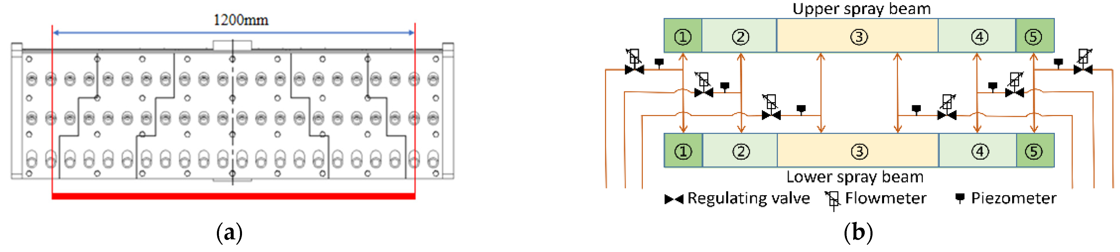
2. New Partition-Cooling Device of Hot Rolling and Its Online Control Method

In order to control the local load roll gap, the cooling water flow rate needs to be changed independently at different positions of the hot roll along the lateral direction. Thus, a new type of partition-cooling beam is designed, as shown in Figure 1a. The red line indicates the width range of the hot strip. According to the product requirements, the cooling beam is divided into five areas along the lateral direction, which includes the middle rapid cooling area, the strip edge cooling area, and two end auxiliary cooling areas. Flow control valves at the pipelines are able to achieve individual control or simultaneous control of the flow rates in each lateral area. The control methods for both upward and downward flow are consistent and synchronized, as shown in Figure 1b. The flow rate corresponding to each nozzle is proportionally adjusted by changing the nozzle aperture or the model setting data; flowmeters and piezometers are used to calculate the opening proportion of water for partition cooling. The number of nozzles is finely designed to match base model and process arrangement. There are three rows of nozzles on both the upper and lower beams, with 10–25 nozzles per row. To ensure the cooling effectiveness of each row of nozzles, the angle between each row of nozzles and the roll surface lateral varies. The angles between the nozzle rows and the roll surface transverse for the upper beam are 5°, 10°, and 10° for the first, second, and third rows, respectively. For the lower beam, the angles are 0°, 5°, and 10° for the first, second, and third rows, respectively. Considering the different distances between each row of nozzles and the roll surface, the lengths of nozzle bases for the first to third rows on the upper beam are 110 mm, 27 mm, and 27 mm, respectively. The lengths of bases for the lower beam are all 110 mm.
Due to the high-temperature nature and the characteristics of hot roll, the partition-cooling beam must be different from the classical static cooling method of hot roll as well as the fine control method of cold roll. By this special partition-cooling system of hot roll, online fine adjustments are achieved to regulate the local load of the roll gap. Obviously, it is helpful in minimizing the occurrence of problems such as the edge drop, the edge wave, and the strip misalignment of silicon steel. The specific control process is illustrated in Figure 2. By selecting the appropriate cooling curve from the sample database, the best process is able to be obtained based on current product specifications and online rolling process parameters. Because the roll thermal expansion is calculated in real time, the shape and crown of the hot strip are formed by practical rolling conditions. Subsequently, the coupled roll profile or the load roll gap is also determined based on the different rolling parameters. According to the quality requirements of product (e.g., shape and crown of the strip), online regulation is carried out at any time. If any deviation is detected, corresponding cooling flow adjustments must be made through the target cooling curve. This iterative process continues until the product quality meets the standards. If the adjusted cooling curve is better than the previous ones, it will be stored in the sample database for subsequent production of products with the same specifications. Moreover, continuous updating and optimization of the sample database are carried out to expand the cooling curves in the database. It is necessary to achieve automation control of any local shape and convexity in the hot-rolling process.

3. Control Model of Partition-Cooling System

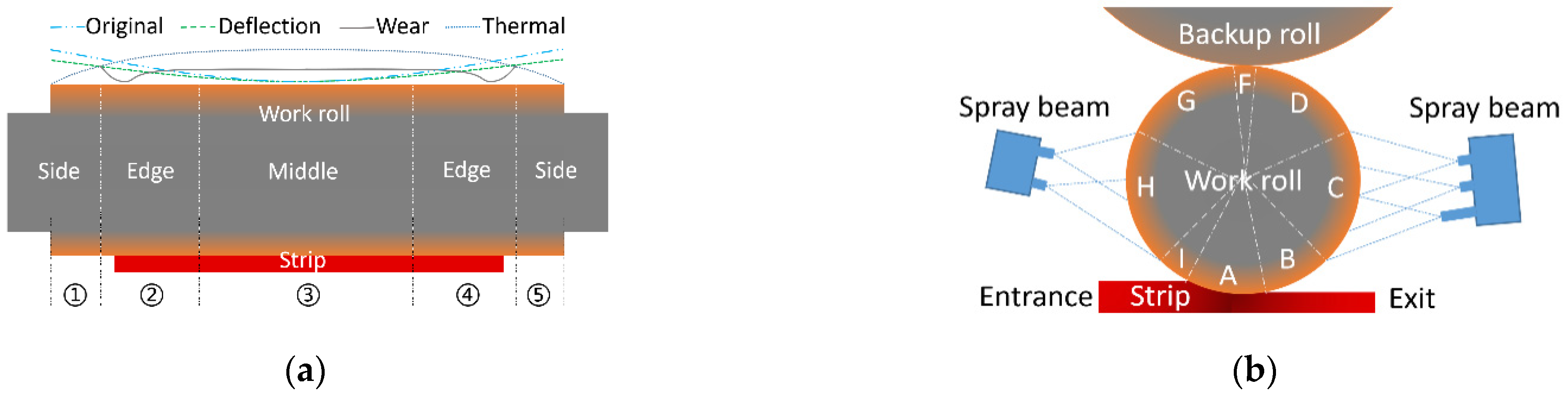
3.1. Dynamic Conditions of Complex Roll Temperature Field

Utilizing the principle of energy conservation, a practical roll’s temperature field model is established by formulating the finite difference equation. First, the roll is discretized by dividing areas along the lateral direction. And, then, the actual temperature changes at various grid points are able to be computed. The grid points are categorized as internal points and surface points, as shown in Figure 3 [22].
Figure 3 represents the energy relationship of surface points and internal points, respectively. The energy at internal grid points comes from the heat transfer with the surrounding four grid points, while surface grid points, in addition to heat transfer with the surrounding points, also exchange heat with the external environment. In Figure 3, the dashed lines represent the control volumes, where i and j are the row and column indices of the corresponding grid points. The i direction is from the core to the surface of the work roll, and the j direction is from the drive side to the operator side. The dashed line represents the controlled volume. The heat increment ΔU according to the law of conservation of energy is expressed as:
Δ U = Q 1 + Q 2 + Q 3 + Q 4
where Q1, Q2, Q3, and Q4, are the heat received by the target grid point from the grid points (i, j − 1), (i, j + 1), (i + 1, j), and (i − 1, j) at the next time step, respectively.
Combining the heat transfer equation of energy at each grid point, the temperature change equations at the corresponding node are established. And, then, the node temperature difference equation for the next time step is obtained. The differential equations for interior grid points of the work roll are expressed as:
T i , j n + 1 = T i , j n + α Δ t ( Δ x ) 2 T i , j 1 n + α Δ t ( Δ x ) 2 T i , j + 1 n + 2 α Δ t ( Δ r ) 2 ( 1 Δ r 4 r Δ r ) T i + 1 , j n [ 2 α Δ t ( Δ x ) 2 + 2 α Δ t ( Δ r ) 2 ( 1 Δ r 4 r Δ r ) + 2 h Δ t ρ c Δ r ( 4 r 4 r Δ r ) ] T i , j n + 2 h Δ t ρ c Δ r ( 4 r 4 r Δ r ) T o u t
The differential equations at the grid points on the roll’s surface are expressed as:
T i , j n + 1 = T i , j n + α Δ t ( Δ r ) 2 T i 1 , j n + α Δ t ( Δ x ) 2 ( T i , j 1 n + T i , j + 1 n ) + α Δ t ( Δ r ) 2 ( r + Δ r r ) T i + 1 , j n ( 2 α Δ t ( Δ r ) 2 + α Δ t ( Δ r ) 2 Δ r r + 2 α Δ t ( Δ x ) 2 ) T i , j n
where α is the thermal conductivity, r is the roll radius, Δr is the radial unit length of the roll, Δx is the length of roll transverse cell, Tn is the current temperature of the roll, Δt is the time step, h is the convective heat transfer coefficient, Tout is the external temperature, ρ is roll density, c is the specific heat capacity of roll, ΔU is the volume variable, and Tn+1 is the roll temperature at the next moment.
Due to the hot-rolling process being complex, the online thermal roll profile plays an important role in the local shape and crown of the strip. In order to enhance the calculation stability and accuracy of the transient temperature field model, it is necessary to conduct a detailed analysis of these boundary conditions during the hot-rolling process in Figure 4.
As shown in Figure 4a, along the lateral direction, the roll is divided into the non-contact low-temperature areas 1 and 5 on both sides, the high-temperature areas 2 and 4 in contact with the hot strip on both sides, and the high-temperature area 3 in the middle of the roll. It is necessary to consider the lateral movement of the rolls and the variation in the strip width during the calculation process. Therefore, the high-temperature area in contact with the strip edge includes a portion of the non-contact low-temperature area. As shown in Figure 4b, the circumferential boundary of the roll is divided into eight different regions, each with specific boundary conditions. This division facilitates the impact of various boundary conditions on the temperature and thermal profile of the roll. Additionally, it allows for the precise setting of equivalent heat transfer conditions. Among them, A is the contact heat transfer in the deformation zone and B and I are the air cooling and the radiation heat transfer at the lower part of the work roll at the exit and entrance, respectively. C and H are the water cooling at the exit and entrance of the work roll, respectively. D and G are the air cooling at the upper part of the work roll at the exit and entrance, respectively. F is the contact heat transfer between the work roll and the backup roll.
During the high-speed rotation of the work roll, the boundary conditions periodically change. To precisely control the partition water flow, it is necessary to apply the equivalent treatment to the boundary conditions of the work roll. In relatively stable operating conditions, the main factors affecting the work roll’s temperature are the strip contact heat transfer coefficient hs0 and the basic heat transfer coefficient hw0 of the cooling water, represented as [23]:
h s 0 = R ( Δ h + 2.2 × 10 5 P r / B s ) 2 π R 15,100 + 230 × ( 4.168 + 1.712 × 10 6 e 0.0146 T s )
h w 0 = κ L r L d + k h r
where R is the work roll’s radius, Δh is the reduction, Pr the rolling force, B is the strip width, Ts is the strip temperature, Lr is the cooling water pressure, Ld is the distance between the nozzle and the roll, κ is the correction coefficient, k indicates whether the inlet cooling water is open, and hr is the heat transfer coefficient of the inlet’s cooling water.
According to Figure 4b, dividing the roll into n regions along the circumferential direction, the basic equivalent heat transfer coefficient heq and basic equivalent temperature Teq are expressed as:
h e q = i = 1 n h i ω i i = 1 n ω i , T e q = i = 1 n h i T i ω i h e q i = 1 n ω i
where hi is the heat transfer coefficient in the i region, ωi is the contact area in the i region, and Ti is the temperature in the i region.
In addition, the comprehensive heat generation process must be required in the hot-rolling process by fine-tuning the boundary conditions. For example, besides normal heat exchange, there is also the frictional heat between the roll and the strip, as well as the deformation heat generated by the strip deformation. Assuming that the deformation heat is entirely absorbed by the strip, the frictional heat is distributed between the roll and the strip in inverse proportion to the temperature [24]. Thus, the heat flux density qd of the deformation heat per unit volume is:
t r = R ( h 0 h 1 ) v r ,   q d = η d σ F ln h 0 h 1 3 t r
The temperature rise caused by frictional heat is as follows:
Δ T f = η f f c ρ l c h m σ F ln h 0 h 1
where tr is the strip’s contact time in the deformation zone, vr is the rolling speed, h0 is the inlet thickness of the strip, h1 is the outlet thickness of the strip, σF is the deformation resistance of the strip, lc is the contact arc length of the deformation zone, hm is the average thickness of the strip in the deformation zone, and ηd and ηf are the heat transfer coefficients of the deformation heat and the friction heat, respectively. According to the above formulas, the online temperature model with high precision and high efficiency is able to be established. Obviously, further optimization and correction of boundary conditions enable accurate prediction of the hot strip.

3.2. Setting Rules of Partition-Cooling System

After installing the partition cooling beams at the exit of the mill, the cooling water flow is able to be regulated in different lateral regions of rolls. And, then, the local thermal roll profile will be changed according to the lateral water flow. However, it is necessary to calculate the online heat transfer coefficient for the corresponding grid points as [23]:
h w = h w 0 h q h p h β h T h d
where hq is the flow density coefficient, hp is the water pressure coefficient, hβ is the nozzle injection angle coefficient, hT is the roll’s temperature coefficient, and hd is the distance coefficient from nozzle.
Considering the practical situation of mill on site, the installation positions of these cooling beams are often fixed. Therefore, except for the water pressure and the water flow density, other coefficients are treated as constants. Combining with the heat transfer coefficient in Equation (5), further processing of water cooling is shown as:
h w = χ h q h p h w 0
where χ is a constant determined by factors such as the installation location.
In the process of designing a partitioned-cooling beam, various parameters, such as the nozzle types, the base lengths, and the angles, differ across different regions. These differences lead to variations in the heat transfer coefficients in the cooling water regions. Analyzing in conjunction with production loading, the opening ratio of the nozzle corresponds to the flow rate and the water pressure of the cooling water. Consequently, by adjusting two types of parameters, it is possible to calculate the sectional heat transfer coefficients for the lateral cooling water. Combining practical production data of the 1580 hot mill, the heat transfer coefficient of water cooling is calculated by Equation (5), where κ is 0.25 and k = 53.9. During the rolling process, the flow rate and the pressure of the cooling water serve as a criterion for determining the opening ratio. And, then, the logical relationship is defined as:
r = L 1 × p 1 L max × p max × 100 %
where r is the opening ratio of the partition-cooling beam, L1 is the practical flow rate of the cooling water, p1 is the practical pressure of the cooling water, Lmax is the maximum water flow rate of the cooling water, and pmax is the maximum pressure of the cooling water.
In the other stable cases, adjusting the flow rate of the cooling water also significantly alters the thermal profile or the load roll gap. Properly, it compensates for the dynamic fluctuations of other roll profiles. The powerful adjustment capability of local roll profile is the most effective method of improving strip edge drop and local crown. When the flow rate is between 0 and 8 L/s, the heat transfer coefficient rapidly increases. This indicates that increasing the water flow effectively regulates the surface temperature of the rolls within this range. When the flow rate is above 8 L/s, the heat transfer coefficient still shows an increasing trend but the rate noticeably slows down. This suggests that, when the water flow reaches a certain level, solely relying on increasing the cooling water flow rate has limited potential to enhance cooling efficiency. In the practical control process, the lateral distribution of the flow rate should be considered as the optimization variable. Clearly, the online thermal roll profile is helpful in minimizing the lateral thickness variations and the edge deviation of the strip.

3.3. Effective Model of Thermal Roll Profile

The online thermal roll profile of the current stand has a direct impact on the subsequent stand, so the partition-cooling curve should be designed and selected to meet the different rolling conditions. This achieves a smooth transition in the roll gap of all stands. Actually, the synchronous coupling calculation is conducted to minimize online forecasting deviations. First, the roll’s temperature distribution is solved in real time based on the practical operating parameters. Simultaneously, the current thermal expansion is computed to forecast subsequent changes in the thermal roll profile. This information serves as the basis for the control adjustments of the local roll gap.
Assuming the work roll as an infinitely long cylindrical body, the temperature field distribution is symmetric about the cross-section of the roll. Simultaneously, by discretizing the integral part, the thermal expansion of the roll of ur is obtained [25].
u r = 2 ( 1 + v ) β r R 0 R ( T T 0 ) r d r
where βr is the linear expansion coefficient, v is the Poisson’s ratio of the roll material, T0 is the initial temperature or the previous temperature, and T is the current roll temperature.
However, it is necessary to consider the cascading relationship of parameters between front and rear stands [26,27]. It is essential for better predicting the evolution pattern of the thermal roll profile. After obtaining these quasi-static rolling parameters and their variations for each stand, the thermal roll profile changes should be isolated for each stand based on the measured data. And, then, the real-time calculation is performed by using the partition cooling to closely match the local roll gap. Meanwhile, based on the measured crown at the exit stand, the most suitable thermal roll profiles will be retro-calculated for each stand. Referring to the technical route in Figure 2, the original profile Co at room temperature, the thermal profile CT, the worn profile Ca, the elastic bending profile Cd, and the anti-symmetric wandering profile caused by the roll shifting CS are set; the multi-parameter coupled profile CZ of the target stand is as shown in Equation (13).
C z = ζ λ o C o + λ T C T + λ a C a + λ d C d + λ s C s + ( 1 ζ ) C z 0
where λo, λT, λa, λd, and λs are the adaptive weighting factors corresponding to the above roll profile, respectively. Cz0 is the setting curve of the last similar working condition and ζ is the adaptive adjustment factor.

4. Experimental Results

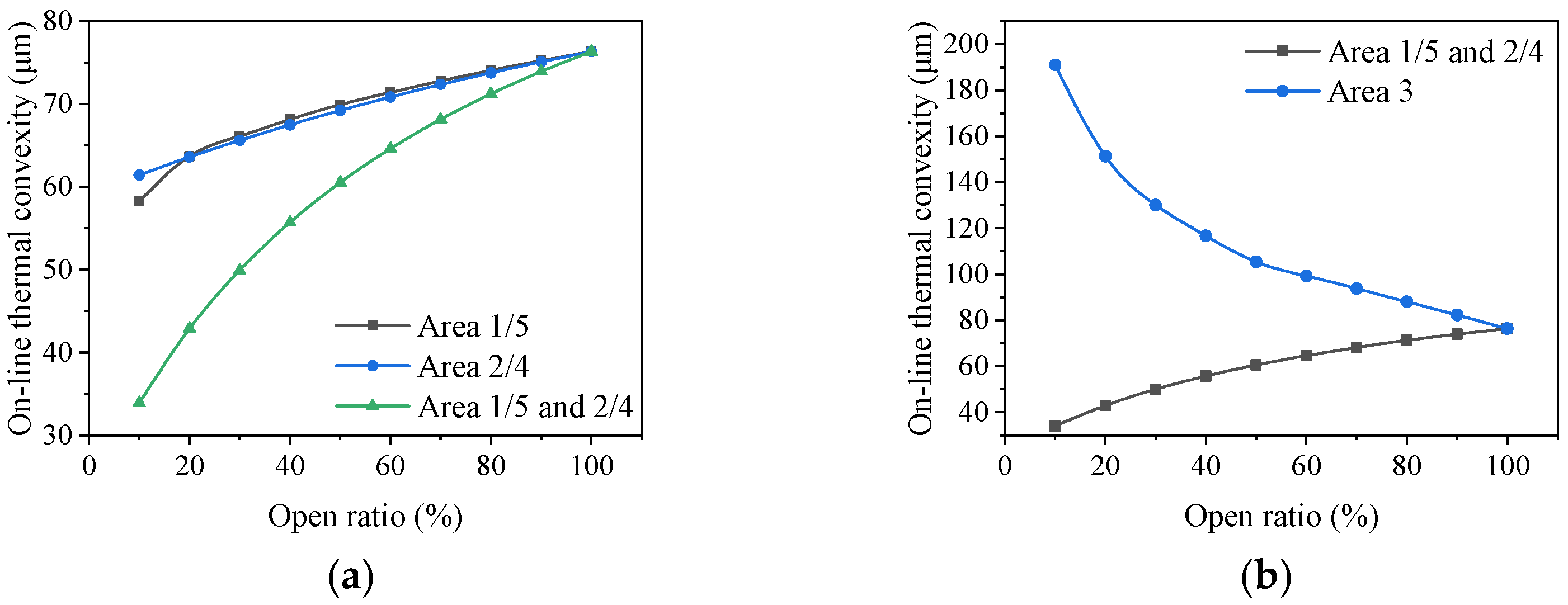
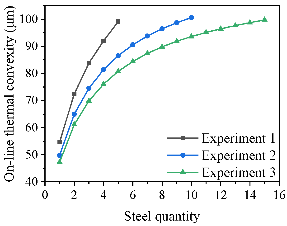
4.1. Analysis of Partition Water Flow Rates

The core of partition cooling lies in achieving precise control of the thermal profile by adjusting the cooling water quantity in each region. Based on this rule, after the new partition-cooling beam was installed at the exit of the mill, some key cooling experiments were conducted. Then, the effects of adjusting the water flow rates, the strip width, and the entry water flow on the thermal profile were analyzed separately. Taking the most typical S14 steel as an example, the strip width was 1200 mm, the rolling pace was 125 s, the pass quantity was 50 pieces, and the roll diameter was 680 mm. The opening ratios of areas 1 and 5 were 10–100%, corresponding to the water flow range of 1.5–13 m3/h. For areas 2 and 4, the opening ratios were 10–100%, corresponding to 1.8–16 m3/h. For area 3, the opening ratios were 10–100%, corresponding to 1.8–16.5 m3/h. During the analysis of one or multiple areas, the water flows in other areas were set at a fixed opening ratio of 100%. By the changes in thermal profile of the edge and center positions under different cooling conditions, the opening ratios and the thermal profiles are shown in Figure 5.
Figure 5a shows the regulation process of the water flow in areas 1/5 and 2/4, as well as the joint regulation of the water flow. When individually controlled in areas 1/5, there was a clear nonlinear relationship in thermal profile. Areas 1/5, as the cooling control area of the roll’s edge, had a thermal profile range of 50–75 μm corresponding to the opening ratios of 10–100%. The roll surface in this area did not contact with the strip; hence, its influence on the central and local convexity was limited. When individually controlled in areas 2/4, the focus was primarily on controlling the contact area between the strip edge and the rolls. The thermal profiles changed corresponding to the opening ratios of 10–100% from 62–76 μm. Its influence on the overall convexity of the roll was relatively weak but significantly affected the local convexity or the strip edge reduction. Through theoretical calculations, it was observed that the individually controlling methods of the opening ratios of areas 1/5 and 2/4 had little impact on the thermal profile of the roll. The regulation at the edges was more suitable for fine-tuning at the local profile. By jointly adjusting the two areas, the control range of the thermal profile reached 33–76 μm. Clearly, this provided a larger range for the thermal profile or the local roll gap. This more flexible adjustment method was able to meet the rapid online adjustment requirements of any thermal roll profiles. From Figure 5b, area 3 had the greatest impact on the thermal profile. The opening ratios of 10–100% corresponded to the range of 76–191 μm. Based on these above requirements, an appropriate opening ratio of area 3 was selected to ensure a suitable temperature range and meet the rated adjustment range.
Moreover, when the strip width ranged from 800 mm to 1250 mm and the pass quantity was 50, the rolling pace was 125 s. The online thermal profile was analyzed for two kinds of limiting water (10% and 100%). And, then, the partition-cooling range under different widths was obtained, as shown in Figure 6.
As shown in Figure 6, for these strip widths of 800 mm, 1000 mm, 1100 mm, and 1200 mm, the corresponding ranges of the thermal profile were 120.6 μm to 277.5 μm, 113.9 μm to 267 μm, 84.8 μm to 252 μm, and 33.9 μm to 216 μm, respectively. Obviously, there was a significant variation in the thermal profiles. The partition-cooling capacity also changed with the variation in the strip width. For example, when the strip width was below 1000 mm, the cooling effectiveness of areas 1 and 5 would significantly decrease.

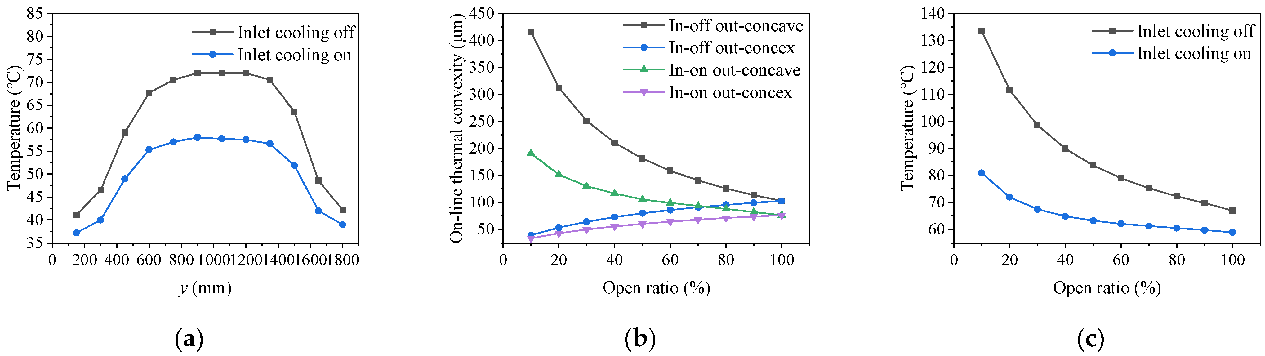
4.2. Influence of the Inlet Water Flow on the Roll Profile

The water-cooling process in hot rolling consisted of two parts: the inlet and the outlet. The inlet water cooling used the uniform flow cooling curve and the outlet water cooling realized the temperature control. Whether the inlet water cooling was turned on or not, by the different water volume of the outlet partition cooling, the roll thermal profile and surface temperature changes were analyzed, as shown in Figure 7.
As shown in Figure 7a, under the same distribution of the outlet water flow, when the inlet water was open, the temperatures at the center and edge of the roll were 58 °C and 37 °C, respectively, with a temperature difference of 21 °C. However, when the inlet water was closed, the temperatures at the center and edge of the roll were 72 °C and 41 °C, respectively, with a temperature difference of 31 °C. The inlet cooling overall affected the water coverage area and the cooling capacity of the roll, which directly influenced the thermal stability to a significant extent. As shown in Figure 7b, based on the cooling status of the inlet water, two types of exit water cooling curves were designed to analyze the comprehensive cooling capacity of the inlet and outlet cooling water. It was observed that, when the inlet cooling was open, the control range of the thermal profile was 34–191 μm. And, when the inlet cooling was closed, the adjustment range was 39.5–415 μm, with a minimum difference of 5.5 μm and a maximum difference of 224 μm. This indicated that the combined adjustment of inlet and outlet water flow had a significant impact on thermal profile. As shown in Figure 7c, during the adjustment process, the cooling at the inlet, combined with the cooling in area 3 of the partition cooling, significantly adjusted the overall range of the thermal profile. In the meantime, the other areas provided refined assistance in the adjustment process. When the inlet water is opened and the partition cooling water at the outlet is adjusted to the lowest, the roll temperature is 90 °C, because 90 °C is more sensitive to the cooling water, especially for the partition cooling of roll. When the inlet water is opened and the partition cooling water at the outlet is adjusted to the lowest, the roll temperature is 90 °C. The purpose is to obtain the corresponding relationship of the cooling effect. At the same time, the roll temperature is gradually reduced during the adjustment of the outlet water volume. The corresponding roll temperature is often set to about 60 °C when the outlet water volume is maximum in practical applications. The safe water quantity range was set to ensure that the roll temperature did not exceed the safety threshold of 90 °C. Based on this, the partition cooling control was implemented to assure the thermal profile of hot silicon steel rolling. At the same time, the roll temperature is gradually reduced during the adjustment of the outlet water volume. The corresponding roll temperature is about 60 °C when the outlet water volume is maximum. In practical applications, the safe water quantity range was often set to ensure that the roll temperature did not exceed 90 °C. Based on this, the partition cooling control was implemented for a more complex thermal profile of hot silicon steel rolling.

4.3. Influence of Cooling Curve on Thermal Roll Profile

Based on theoretical analysis and empirical observations, it was evident that partition cooling was highly effective in adjusting the thermal roll profile. To better meet the specifications for the shape, the convexity, and the local load roll gap, it is necessary to implement partition cooling control to achieve the specific thermal roll profile and the best shape. The diameters of upper roll and lower work were the same, although there was some difference in the practical process, the overall pattern was almost consistent. According to different water distribution curves under rolling parameters in Table 1, the set water opening ratios for each section are indicated in Table 2. The corresponding thermal profiles are illustrated in Figure 8.
In Figure 8, the stable thermal profile is formed in less time by different the partition-cooling modes. It was very meaningful to minimize fluctuations of rolling process. Based on this important rule, the better cooling curves should be designed to satisfy special requirements of the silicon steel rolling process.

5. Industry Application

The 1580 mill was mainly used for rolling silicon steel of 800~1250 mm. Considering the stability and safety of production, the F5 stand was selected to observe the influence of different partition-cooling curves on the thermal roll profile and the strip crown. The work roll diameter was 680 mm. The new cooling system was divided into upper and lower parts, corresponding to the upper and lower work roll, respectively. The cooling beam of 1249 kg was entirely made of stainless steel material. Each cooling beam needed 132 cooling nozzles. And the control system was equipped with five groups of the control valve, the flow meter, and the pressure gauges. The response time of the valve was within 10 s. The working pressure was in 0.1–1.8 MPa. Accuracy of thermometer was ±0.1 °C. Up to now, this new partition-cooling beam has been applied on the F5 stand for over a year, running stably, and has formed a cooling standard process. And further testing will be conducted on the cooling effectiveness of F6 and F7. By utilizing partition cooling to assist the mechanical control methods, traditional control strategies will be broken through and the local profile will be finely adjusted to achieve good indexes and minimal edge drop of the strip.
The production capacity and strip quality have greatly improved under different water flow conditions for the varied steel grade. Two typical tests were used as cases to verify the industrial application effect of partition cooling. Two sets of experiments are shown in Table 3, and the water quantities of all cooling regions are presented in Table 4. After the rolling process, offline measurements were taken for obtaining the temperature of the roll surface by a contact thermometer. The comparisons between the measured results and the calculated rules are depicted in Figure 9.
As shown in Figure 9, the surface temperature varied obviously with different partition-cooling conditions. In Experiment 1, the measured temperature at the middle position of the roll was 65.7 °C, and the corresponding calculation result was 65 °C. In Experiment 2, the measured temperature at the middle position of the roll was 66.6 °C, and the calculation result was 66.2 °C. Taken overall, the error was within 5%, which demonstrated the new model had a good predictive performance. Before the modification, different temperatures were measured under 10 different operating conditions. After the modification, the same measurements were performed. These temperature differences are shown in Figure 10. It shows that the deviation of the original mode was stable at 7–12 °C but those of the modified mode were within 5 °C.
Based on different rolling processes, the water flow rates for all areas were calibrated after the modification. The cooling modes were applied to the practical production process, as shown in Table 5. Through the optimization in each area, the temperature difference between the two sides of the roll had improved from 6.1 °C to 0.7 °C, as shown in Figure 11.
By the new partition-cooling system of hot silicon steel, the dynamic control of the roll thermal expansion has been finished. In the practical process, a relatively small amount of water in the central region was able to be set to quickly establish the basic thermal roll profile in the early stages of rolling. It ensured a stable production state. Based on the process requirements, partition cooling was dynamically adjusted to achieve high-quality production. The C40 is the thickness difference between the middle of the strip and 40 mm from the edge of the strip, which is often measured by the thickness measuring system at the outlet of the production line. Now, the hitting rate of C40 has increased by 33%. It significantly reduces the quality fluctuation of the product, as shown in Figure 12.

6. Conclusions

  • A new partition-cooling system of the hot rolling process has been designed to achieve online control of the thermal profile and the precise setting of the lateral roll gap. This enables rapid adjustments of the water flow and the distribution according to the rolling process goals, which provides an effective method for quickly adjusting the local roll gap and the strip shape or the edge drop.
  • An online temperature prediction model has been constructed for the partition-cooling process. Based on the practical production conditions and the partition-cooling modes, most cases were handled to achieve accurate temperature prediction by considering complex conditions in hot continuous rolling. According to the experimental results of partition cooling, the prediction error was within 5%.
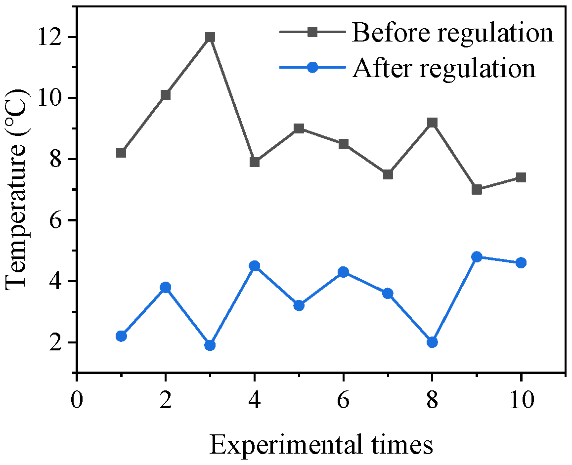
  • After application of the partition-cooling system, the temperature difference between the upper and lower rolls was within 5 °C, the lateral edge temperature difference was within 0.7 °C, and the hit rate of C40 increased by 33%.

Author Contributions

Conceptualization, Q.W. and L.Y.; methodology, J.S.; software, Z.Z.; validation, L.D. and J.L.; formal analysis, Q.W.; investigation, L.D and H.W.; resources, Y.J. and H.W; data curation, Q.W.; writing—original draft preparation, J.Y.; writing—review and editing, L.Y.; supervision, J.S.; project administration, Q.W. All authors have read and agreed to the published version of the manuscript.

Funding

This research was funded by Returned Overseas Scholar Foundation of Hebei Province (Grant No. C20210321), Natural Science Foundation of Hebei Province (Grant No. E2021203106), and S&T Program of Hebei (Grant No. 236Z1019G).

Data Availability Statement

The original contributions presented in the study are included in the article, further inquiries can be directed to the corresponding authors.

Conflicts of Interest

Authors Qiuna Wang, Haishen Wang, Lijie Dong, Yanlong Jiao and Jieming Li were employed by the Shougang Company Limited. The remaining authors declare that the research was conducted in the absence of any commercial or financial relationships that could be construed as a potential conflict of interest. The Shougang Company and the funders had no role in the design of the study; in the collection, analyses, or interpretation of data; in the writing of the manuscript, or in the decision to publish the results.

References

  1. Özgür, A.; Uygun, Y.; Hütt, M.-T. A Review of Planning and Scheduling Methods for Hot Rolling Mills in Steel Production. Comput. Ind. Eng. 2021, 151, 106606. [Google Scholar] [CrossRef]
  2. Huang, Q. Research Progress on Key Equipment and Technology of High Quality Steel Plate and Strip Rolling. J. Mech. Eng. 2023, 59, 34–63. [Google Scholar]
  3. Peng, Y.; Shi, B.; Liu, C.; Xing, J. Review of the Integrated Development of Strip Rolling Equipment process-product Quality Control. J. Mech. Eng. 2023, 59, 96–118. [Google Scholar]
  4. Müller, M.; Prinz, K.; Steinboeck, A.; Schausberger, F.; Kugi, A. Adaptive Feedforward Thickness Control in Hot Strip Rolling with Oil Lubrication. Control Eng. Pract. 2020, 103, 104584. [Google Scholar] [CrossRef]
  5. Shi, X.; Feng, D.; Sun, F.; Liu, X.; Zhang, F. Hor Rolling Equipments and Technical Progress for Electrical Steel in China. Electr. Steel 2022, 4, 6–15. [Google Scholar]
  6. Shao, J.; He, A.; Yang, Q.; Jiang, L.; Yao, C.; Zhou, B. Multi-parameter Coupled Subsection Cooling Regulation Characteristics of Work Rolls in Aluminum Cold Rolling. Chin. J. Eng. 2015, 37, 1092–1097. [Google Scholar]
  7. Zhang, Y.; Li, X.; Zhao, M.; Qu, F.; Zhang, Y.; Peng, W.; Zhao, D.; Di, H.; Zhang, D. Novel Analytical Heat Source Model for Cold Rolling Based on an Energy Method and Unified Yield Criterion. Int. J. Adv. Manuf. Technol. 2022, 122, 3725–3738. [Google Scholar] [CrossRef]
  8. Wang, P.; Deng, J.; Li, X.; Hua, C.; Su, L.; Deng, G. A Novel Strategy Based on Machine Learning of Selective Cooling Control of Work Roll for Improvement of Cold Rolled Strip Flatness. J. Intel. Manuf. 2023, 11. [Google Scholar] [CrossRef]
  9. Gao, S.; Liu, H.; Xi, A.; Yang, X. Closed-loop Control Strategy of Segmented Cooling in Hot Rolling of Aluminum Alloys. J. Mech. Eng. 2016, 52, 207–212. [Google Scholar] [CrossRef]
  10. Guo, X.; He, A.; Shao, J.; Zhou, B.; Li, Q. Modeling and Simulation of Subsectional Cooling System during Hot Aluminum Rolling. J. Mech. Eng. 2013, 49, 70–74. [Google Scholar] [CrossRef]
  11. Bohacek, J.; Raudensky, M.; Kotrbacek, P. Remote Cooling of Rolls in Hot Rolling; Applicability to Other Processes. Metals 2021, 11, 1061. [Google Scholar] [CrossRef]
  12. Wang, X.; Zhang, W.; Ai, Y. Influence of Edge Thermal Spraying on the Temperature Field and Thermal Crown of Work Roll during Cold Rolling of Aluminum Alloy Strip. Int. J. Adv. Manuf. Technol. 2023, 127, 4331–4338. [Google Scholar] [CrossRef]
  13. Yang, L.; Wang, D.; Yu, B.; Wang, Y. Research on the Quick Simulation Model for the Transient Temperature Field of the Hot Roll. J. Plast. Eng. 2010, 17, 123–128. [Google Scholar]
  14. Gavalas, E.; Papaefthymiou, S. Thermal Camber and Temperature Evolution on Work Roll during Aluminum Hot Rolling. Metals 2020, 10, 1434. [Google Scholar] [CrossRef]
  15. Han, G.; Li, H.; Zhang, J.; Kong, N.; Liu, Y.; You, X.; Xie, Y.; Shang, F. Prediction and Analysis of Rolling Process Temperature Field for Silicon Steel in Tandem Cold Rolling. Int. J. Adv. Manuf. Technol. 2021, 115, 1637–1655. [Google Scholar] [CrossRef]
  16. Wu, H.; Sun, J.; Lu, X.; Peng, W.; Wang, Q.; Zhang, D. Predicting Stress and Flatness in Hot-Rolled Strips during Run-out Table Cooling. J. Manuf. Process. 2022, 84, 815–831. [Google Scholar] [CrossRef]
  17. Hu, K.; Xue, R.; Shi, Q.; Han, W.; Zhu, F.; Chen, J. FEM Simulation of Thermo-Mechanical Stress and Thermal Fatigue Life Assessment of High-Speed Steel Work Rolls during Hot Strip Rolling Process. J. Therm. Stress. 2022, 45, 538–558. [Google Scholar] [CrossRef]
  18. Li, Z.; Liu, L.; Yin, B.; Kuang, S.; Wang, J.; Bai, Z. Research on Roll Temperature Field and Hot Roll Crown of Hot Continuous Rolling Mills. Iron Steel. 2023, 10. [Google Scholar] [CrossRef]
  19. Bao, Q.; Zhang, S.; Guo, J.; Xu, Z.; Zhang, Z. Modeling of Dynamic Data-Driven Approach for the Distributed Steel Rolling Heating Furnace Temperature Field. Neural Comput. Applic. 2022, 34, 8959–8975. [Google Scholar] [CrossRef]
  20. Li, F.; He, A.; Song, Y.; Wang, Z.; Xu, X.; Zhang, S.; Qiang, Y.; Liu, C. Deep Learning for Predictive Mechanical Properties of Hot-Rolled Strip in Complex Manufacturing Systems. Int. J. Min. Met. Mater. 2023, 30, 1093–1103. [Google Scholar] [CrossRef]
  21. Meng, L.; Ding, J.; Dong, Z.; Sun, J.; Zhang, D.; Gou, J. Prediction of Roll Wear and Thermal Expansion Based on Informer Network in Hot Rolling Process and Application in the Control of Crown and Thickness. J. Manuf. Process. 2023, 103, 248–260. [Google Scholar] [CrossRef]
  22. Yang, L.; Jiang, Z.; Zhu, J.; Yu, H. Analysis of Transient Heat Source and Coupling Temperature Field during Cold Strip Rolling. Int. J. Adv. Manuf. Technol. 2018, 95, 835–846. [Google Scholar] [CrossRef]
  23. Li, Y.; Cao, J.; Qiu, L.; Yang, G.; Kong, N.; He, A.; Zhou, Y. Effect of Strip Edge Temperature Drop of Electrical Steel on Profile and Flatness during Hot Rolling Process. Adv Mech. Eng. 2019, 11, 753305129. [Google Scholar] [CrossRef]
  24. Chen, C.; Shao, J.; He, A. Research on Online Calculation Methods of Temperature Field of Hot Strip. J. Mech. Eng. 2014, 50, 135–142. [Google Scholar] [CrossRef]
  25. Wang, L.; Ma, L.; Song, Z. Shape Control Model of Magnesium Alloy Single-stand Four-high Mill. J. Netshape Form. Eng. 2022, 14, 36–43. [Google Scholar]
  26. Peng, G.; Xu, D.; Zhou, J.; Yang, Q.; Shen, W. A Novel Curve Pattern Recognition Framework for Hot-Rolling Slab Camber. IEEE Trans. Ind. Inform. 2023, 19, 1270–1278. [Google Scholar] [CrossRef]
  27. Peng, G.; Cheng, Y.; Wang, H.; Shen, W. Industrial Big Data-driven Mechanical Performances Prediction for Hot-rolling Steel Using Lower Upper bound Estimation Method. J. Manuf. Syst. 2022, 65, 104–114. [Google Scholar] [CrossRef]
Figure 1. Partition-cooling system: (a) partition-cooling beam; (b) flow control method.
Processes 12 00410 g001
Figure 2. Partition-cooling control process of hot-rolling process.
Processes 12 00410 g002
Figure 3. Grid points and their energy transfer relationship in the roll: (a) surface grid points of the roll; (b) internal grid points of the roll.
Processes 12 00410 g003
Figure 4. Boundary conditions of the work roll: (a) lateral partition; (b) circumferential cooling conditions.
Processes 12 00410 g004
Figure 5. The relationship between the opening ratios and the thermal profiles: (a) the independent regulations and the joint regulations; (b) opening ratio and thermal convexity in area 3.
Processes 12 00410 g005
Figure 6. Thermal profile range of different strip widths.
Processes 12 00410 g006
Figure 7. The temperature and the thermal profile: (a) offline roll temperature; (b) influence of the inlet water flow under different cooling curves; (c) relationship between the opening ratio of area 3 and the inlet water flow.
Processes 12 00410 g007
Figure 8. Different cooling curves.
Processes 12 00410 g008
Figure 9. Surface temperatures of the offline roll: (a) Experiment 1; (b) Experiment 2.
Processes 12 00410 g009
Figure 10. Temperature differences between upper and lower rolls before and after regulation.
Processes 12 00410 g010
Figure 11. Comparison of roll temperature distribution before and after water adjustment.
Processes 12 00410 g011
Figure 12. Comparisons of C40.
Processes 12 00410 g012
Table 1. Rolling parameters.
Steel GradeWidth (mm)Force (kN)Rhythm (s)ThroughputRoll Diameter (mm)
S14120011,88212550680
Table 2. Opening ratio of cooling water.
Area 1 (%)Area 2 (%)Area 3 (%)Area 4 (%)Area 5 (%)
Experiment 110010032100100
Experiment 210010043100100
Experiment 310010056100100
Table 3. Experimental rolling parameters.
Steel GradeWidth (mm)Exit Thickness (mm)Rhythm (s)Force (kN)Throughput
Experiment 1S1411292.61331080456
Experiment 2S1411502.61241164760
Table 4. The opening ratio of each area of partition cooling.
Area 1 (%)Area 2 (%)Area 3 (%)Area 4 (%)Area 5 (%)
Experiment 11030903010
Experiment 27080408070
Table 5. The opening ratio of each area before and after the adjustment.
Area 1 (%)Area 2 (%)Area 3 (%)Area 4 (%)Area 5 (%)
Before adjustment70801008070
After adjustment56741008684
Disclaimer/Publisher’s Note: The statements, opinions and data contained in all publications are solely those of the individual author(s) and contributor(s) and not of MDPI and/or the editor(s). MDPI and/or the editor(s) disclaim responsibility for any injury to people or property resulting from any ideas, methods, instructions or products referred to in the content.

