Article

Thermodynamic Analysis and Economic Assessment of Organic Rankine Cycle Integrated with Thermoelectric Generator Onboard Container Ship

by
Ahmed G. Elkafas
1,2
1
Thermochemical Power Group (TPG), DIME, University of Genoa, 16145 Genova, Italy
2
Department of Naval Architecture and Marine Engineering, Faculty of Engineering, Alexandria University, Alexandria 21544, Egypt
Processes 2024, 12(2), 355; https://doi.org/10.3390/pr12020355
Submission received: 17 January 2024 / Revised: 1 February 2024 / Accepted: 7 February 2024 / Published: 8 February 2024
(This article belongs to the Special Issue Processes in 2023)

Abstract

:
In July 2023, the International Maritime Organization (IMO) presented an updated strategy for decarbonizing maritime transport and achieving net-zero greenhouse gas emissions by 2050. It is therefore imperative to explore innovative solutions to achieve a blue economy and maximize energy efficiency on-board ships. For this reason, the current study aims to integrate the organic Rankine cycle (ORC) and thermoelectric generator (TEG) on board a container ship to generate electrical energy and reduce fuel consumption. The combined system will benefit from the waste heat of a marine diesel engine installed on board. The current study uses R245fa as the organic liquid and analyzes the effects of varying the evaporation pressure on the energetic and economic performance indicators by modeling the combined system in Engineering Equation Solver (EES) software. The results show that the energy efficiency of the ORC system increases from 12.3% at 3.5 bar to 17.3% at 8 bar. In comparison, the energy efficiency of the TEG unit is 6.9% at different evaporation pressures. In addition, the energy efficiency of the TEG-ORC system is 18.3% with an output of 1386 kW at 8 bar, which is an increase of 30.5% compared to the value at 3.5 bar. This generated power reduces fuel consumption by around 1580 ton/year. From an economic point of view, the energy production cost of the combined system is USD 618/kWh and USD 614/kWh at the lowest and maximum evaporation pressure, respectively. Fuel costs and CO2 tax expenditures could be reduced by up to USD 1.169 million/year and USD 0.47 million/year, respectively, through the combined TEG-ORC system.

1. Introduction

The International Maritime Organization (IMO) has developed several laws and guidelines to regulate greenhouse gas (GHG) emissions from ships, intending to reduce these pollutants by almost 30% by 2030 and 80% by 2040 compared to the pollutants produced in 2008 [1,2]. To achieve this goal, numerous operational and technological strategies have been developed to reduce greenhouse gas emissions and increase energy efficiency on board ships [3,4].
Since almost half of the energy supplied to the ship’s engine by the fuel is released as waste heat (WH) by exhaust gases, lubricating oil, scavenging air, cooling water, and radiation [5,6], the scientific community is seeking out techniques to use this waste energy as efficiently as possible [7,8]. For this reason, waste heat recovery (WHR) is considered an effective measure to lessen the environmental effect of maritime transportation as well as its operational costs by reducing fuel expenses. In addition, WHR technologies are easier to implement on board than investing in an advanced power generation system such as fuel cells or batteries, as WHR technologies can be installed on board in-service vessels with minor modifications in the engine room [9].
There are several scenarios for recovering waste energy such as WH-to-power, WH-to-storage, WH-to-upgrade, and WH-to-cooling [10]. Each scenario has a contribution to achieve energy and cost-efficient zero WH on board, taking into account the end-users’ needs and the particular technical characteristics of the ship types. The WH-to-power scenario will be investigated further as it is the current object of study.
The power generation from WH available on-board ships is dependent on the WH source temperatures; therefore, it is considered one of the thermodynamic limitations of applying WH-to-power technologies. The WH sources that are characterized by medium or high temperatures are considered more economically feasible and practical for power generation. The technologies that can produce electric power from medium to high temperatures [11] are Turbo-compounding (PTG, STG, Combined ST-PT) [12], steam Rankine cycles [13], and thermoelectric generation [14]. Other technologies can lower the limit of WH temperature such as organic Rankine cycles (ORCs) [15], Kalina cycles (KCs) [16], and Isobaric Expansion Engines [17] that can produce power from low-medium temperatures. Table 1 summarizes WHR technologies that can produce power from WH with some characteristics such as their temperature range, recovery source, capacity, and efficiency [11,18].
The WH to power technology proposed in the current study is the organic Rankine cycle (ORC), which uses an organic medium on the same principle of steam Rankine cycles, and the utilization of organic fluids gives the advantage of recovering low-temperature WH from jacket water and charge air. ORC is considered advantageous in terms of the efficiency and simplicity of the system [19]. Moreover, it can recover WH from exhaust gases by integrating an exhaust bypass into the system and an economizer for heat capturing. The efficiency of ORC ranges between 5 and 25%, and the high efficiency is partly because it can generate power at lower load factors from the main engine [20].
Several prior review publications by other researchers [6,21] had looked into WHR installation on-board ships based on ORC with an emphasis on the current trends of this technology and its prospective future. After examining three cycles—ORC, KC, and SRC—in an integrated scenario using a large naval two-stroke diesel engine, Ulrik et al. [22] concluded that the ORC had the most potential to improve the engine’s fuel consumption. By collecting data from a chemical tanker, Baldi et al. [23] were able to create an operational profile. This profile was then utilized to construct an improved ORC, which resulted in a fuel consumption decrease of up to 11.4%. After reviewing the deployment of ORC on-board ships, Mondejar et al. [24] concluded that flue gases and jacket cooling water represented the ideal heat sources for this technology. A simulation has been conducted as shown in [20] onboard a passenger ship based on quasi-steady-state modeling to examine the effectiveness of a regenerative ORC, and the results show the capability of ORC to cover 22% of power demand during a round trip. A technical examination of ORC technologies has been conducted by Chintala et al. [25] to investigate the viable working fluid; the results concluded that R245fa is recommended as a viable option.
Thermoelectric generators (TEGs) are devices based on solid-state semiconductors designed to convert thermal power into electrical power. A set of thermoelectric modules is arranged between two heat exchangers with each thermoelectric module being composed of up to hundreds of thermoelectric pairs (electrically in series and thermally in parallel) [14]. TEG is regarded as one of the most likely WHR approaches to improve energy conversion because of its many benefits [26,27,28], including low maintenance requirements, great durability, environmental friendliness, silent operation, and its ability to be integrated with other WHR technologies. As seen in [29,30,31,32], this technology has been used in space, aircraft, automotive, and maritime applications. For TEG applications on-board vessels, Kristiansen et al. [14] investigated the integration of TEGs on board a bulk carrier through test records; the results concluded that a total of 133 kW can be recovered from different WH sources with different temperatures and quantities. In order to evaluate the low-grade WH recovery potential of TEG on-board ships, Georgopoulou et al. [33] designed thermodynamic and dynamic models of TEG integrating with ship components. The results showed that TEG can recover 1 kW and 26 kW from WH available in the auxiliary engine exhaust gas and the main engine’s scavenge air, respectively. Furthermore, numerical research has been conducted by [34] to assess the performance of TEG on recovering the WH available from a marine engine; the findings demonstrate the ability of TEG to recover 2.9% of exhaust heat, which has a flow rate equal to 5.7 m3/s.
It has been discovered that employing a single WHR system to recover WH on-board ships has its limits. The high temperature of exhaust gases, which causes a significant temperature differential with the working fluids, is one of the challenges in employing ORC to recover waste heat from them on-board ships [6,35]. Furthermore, because the working fluid can dissolve at a temperature greater than that, the majority of working fluids that can be employed in ORC have a decomposition temperature that limits their ability to benefit shipboard exhaust gas levels.
In order to recover more waste heat and generate more electrical power, the integration of the ORC system with the TEG device is proposed in the current article. The paper’s goal will be accomplished by simulating the interaction between the marine engine’s waste energy streams (exhaust gases, jacket water cooling, and scavenge air) and the TEG-ORC system. Using an Engineering Equation Solver (EES), the thermo-economic study has been modeled. This article uses R245fa as the organic working fluid and studies the impact of varying the evaporation pressure of the organic fluid on the energy performance indicators such as net generated power, waste heat rate, and energy efficiency of both TEG and ORC systems and the combined system. Moreover, the paper investigates the economic feasibility of TEG-ORC system installation by evaluating the energy production cost, annual fuel cost savings, annual CO2 tax reduction, and discounted payback time of the investment.

2. Engine and WHR System Description

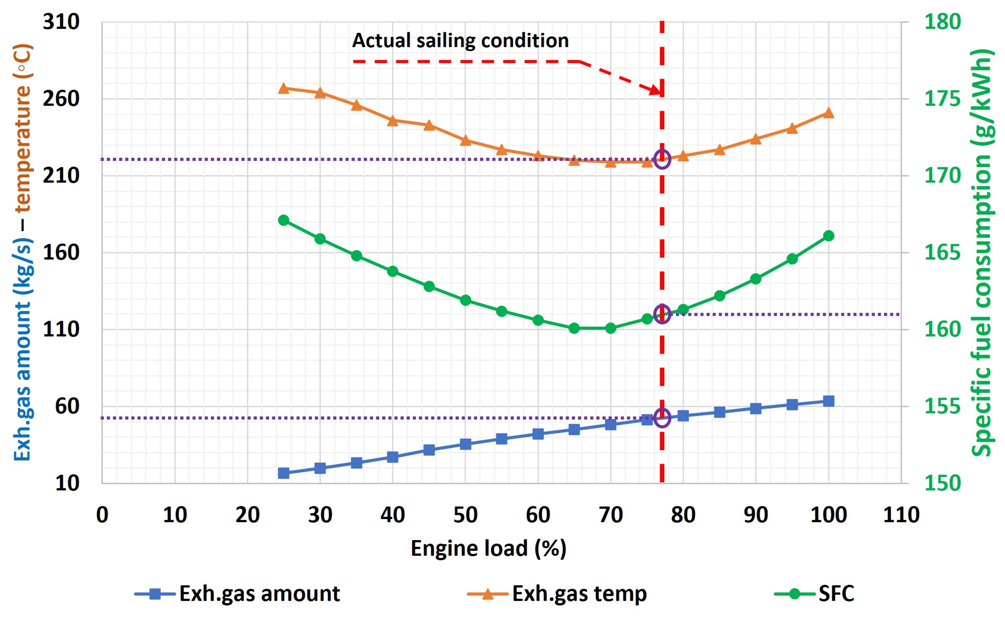
2.1. Marine Engine Description

The integrated TEG-ORC system is proposed to recover the WH from a marine diesel engine installed on board a container ship. The ship has an overall capacity of 3950 TEU (twenty-foot equivalent unit) corresponding to 51,741 tons as a maximum deadweight; its main parameter has been reported before by the author [36].
This ship has an overall length, breadth, and depth of 262 m, 32 m, and 20 m, respectively. At the actual sailing condition, the ship sails at a service speed equal to 23.7 knots and a real draft of 10.33 m; this speed can be reached by using a rated power of 32.7 MW which is 77% of the specified maximum continuous rating (SMCR) of the installed main engine (42.5 MW). This main engine belongs to the two-stroke engine type from MAN with model number MAN 8S90ME-C. The engine’s main specification is reported in Table 2 [37]. Moreover, Figure 1 shows the fuel consumption rates and exhaust gas data at different engine loads focusing on the data of the actual sailing condition at 77% load factor (these data have been extracted from the engine datasheet through MAN CEAS) [38].
The heat dissipation from the engine is divided into five different streams as shown in Figure 2; this Sankey diagram has been developed by the author based on the data extracted from the engine data sheet and correlated at the rated service power of 32.7 MW [37,38]. As shown in Figure 2, the exhaust gases, jacket cooling water, and scavenging air contribute 25.7%, 5.8%, and 9.7% of fuel energy, respectively. Moreover, the temperature of the exhaust gases, jacket cooling water, and scavenge air are 221 °C, 85 °C, and 100 °C, respectively.

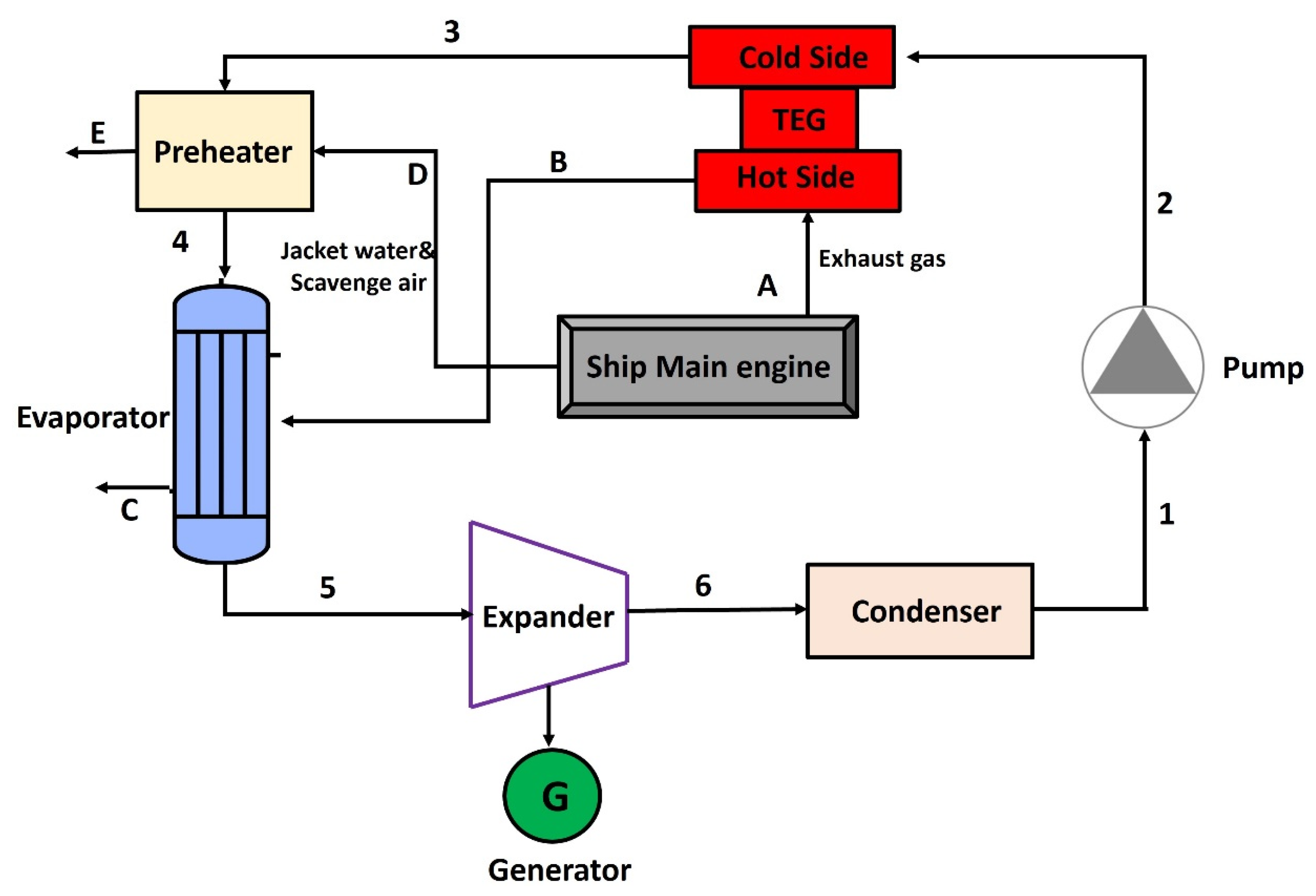
2.2. WHR System Description

At a low cost, the TEG system can collect WH at high temperatures even if its energy efficiency is rather poor. Although ORC technology is generally effective in recovering WH at medium and low temperatures, it has a large footprint and high system power production costs. Therefore, it is proposed in the current study to integrate TEG and ORC systems to achieve energy and cost-efficient zero WH to maximize performance and output power from the WH sources that are accessible on-board ships. Figure 3 shows the system flow schematic for the integration between the TEG-ORC system and the main engine WH streams. The suggested system consists of the following components: pump, TEG, preheater, condenser, expander, and evaporator.
The combined system is proposed to benefit from the exhaust gases from the main engine as a heat source in the TEG unit while utilizing jacket cooling water and scavenge air as a heat source in a preheater to increase the temperature of the working medium before entering the evaporator. The high temperature with high-pressure working medium is released from the evaporator to be expanded in an expander which provides enough power to run the integrated generator. Then, the low-pressure vapor enters the condenser to be condensed and enters the pump which delivers the working medium to the TEG’s cold side.

3. Energy and Economic Analysis Methods

3.1. Thermal Modeling of TEG-ORC System

Engineering Equation Solver (EES) software is used to simulate and model the integrated TEG-ORC system’s performance. The model is developed based on thermodynamic laws, and every part of the TEG-ORC cycle is regarded as a control volume for the purposes of energy modeling. Starting with the pumping of organic fluid into the system, the power and efficiency of the pump can be calculated as shown in Equation (1).
W p u = m o f × h 2 h 1 ,   η p u = v 1 × ( P 2 P 1 ) h 2 h 1
where W p u , m o f , and η p u are the pump power in kW, the mass flow rate of organic fluid in kg/s, and pump efficiency, respectively. The specific enthalpy of organic fluid at the inlet and outlet of the pump are h1, and h2 measured in kJ/kg, respectively. As shown in Figure 1, the pump is followed by the TEG unit, which is composed of the cold side and hot side; Equation (2) can be used to calculate the heat released on the cold side by using the organic fluid data [39].
Q C = m o f × ( h 3 h 2 )
where QC is the heat absorption rate on the cold side and h 3 is the enthalpy of organic fluid at the outlet of the cold side. The efficiency of TEG may be calculated using Equation (3), which is based on the theory of the thermoelectric efficient liquid-based electricity generation apparatus [40].
η T E G = ( 1 T L T H ) × 1 + Z T M 1 1 + Z T M + T L T H
where Z T M is a variable depending on the TEG material, and its value can be in the range of 0.2 and 1.6; for the current study, it will be considered as 0.8 [41]. On the other hand, T L and T H are the average temperature of organic fluid and exhaust gases across the cold side and hot side, respectively. Therefore, the TEG power can be calculated as the product of the heat absorption rate at the cold side and the TEG efficiency [40].
The TEG cold side is employed as a first-stage preheater to the organic fluid before entering the ORC cycle. Then, there is a heat exchanger (preheater) installed to increase the temperature of the organic fluid by using the WH available in jacket cooling water (jw) and scavenge air (sa); the heat balance inside the preheater is described in Equation (4).
Q p r e = m o f × h 4 h 3 = m ˙ j w , s a × ( h D h E )
where Q p r e and m ˙ j w , s a are the waste heat rate at the preheater in kW and mass flow rate of jacket cooling water and scavenged air measured in kg/s, respectively. After that, the organic fluid is directed into the evaporator, and it is converted into vapor by absorbing the WH available at the exhaust gas stream. The energy balance equation for the evaporator is shown in Equation (5)
Q e v a p = m o f × h 5 h 4 = m e x h × h B h C
where h B and h C are the specific enthalpy of exhaust gas at the inlet and outlet of the evaporator, respectively. Also, Q e v a p is the waste heat rate of the evaporator in kW. The saturated vapor produced from the evaporation process is injected into the expander to produce mechanical power based on the expansion process, which can be converted to electrical power by installing a generator. The expander’s electric power can be calculated as shown in Equation (6).
W e x p = m o f × h 6 h 5 × η m ,   η e x p = h 6 h 5 h 6 h 5 s
where W e x p , η e x p , and η m are the expander power in kW, expander efficiency, and mechanical efficiency, respectively. There is a condenser in the proposed system configuration to condense the organic fluid and convert it to saturated liquid again; the energy balance of the condenser is shown in Equation (7).
Q c o n d = m o f × h 1 h 6 = m c w × ( h c w , o u t h c w , i n )
where Q c o n d , and m c w are the condenser’s heat rate in kW and cooling water mass flow rate in kg/s, respectively. Furthermore, h c w , i n , and h c w , o u t are the specific enthalpy of cooling water at the inlet and outlet of the condenser, respectively.
It is expected that variations in kinetic and potential energy are minimal; therefore, they are ignored in the current study. The different components of the integrated system are assumed to be simulated under steady-state conditions. The main parameters inserted into the EES software as inputs in the modeling phase to evaluate the specific cycle performance are listed in Table 3.
There are parameters referring to the hot source data such as the mass flow rate of exhaust gases ( m e x h ), the temperature of exhaust gases ( T e x h ), the temperature of scavenge air ( T s a ) and the temperature of jacket cooling water ( T j w ). Meanwhile, there are other independent variables such as the approach point ( T a p p ), which refers to the temperature difference between the WH source and the working medium temperature at the evaporator. Moreover, the pinch point temperature difference at the hot source ( T p p 1 ) and cold source ( T p p 2 ) are defined as independent variables.
The process of choosing a suitable organic fluid for the current study is challenging, and the subject has drawn a lot of interest from scientists. Based on several working fluids, Tian et al. [42] studied the techno-economic effectiveness of an ORC, and the results showed that R123 and R245fa have the greatest power generation capability and highest thermal efficiency. Moreover, the findings of the study conducted by Larsen et al. [43] showed that R245fa as a working medium for maritime applications seems to be doable with little risk. Consequently, the current study employs R245fa as an organic fluid in the combined TEG-ORC system. R245fa has a chemical formula of CF3CH2CHF2 with a molecular weight of 134.05 g/mol. The critical temperature and pressure of R245fa are 154.01 °C and 36.5 bar, respectively [44,45].
The energy performance indicators of the thermodynamic model are the net output power and energy efficiency of the ORC system, TEG system, and integrated TEG-ORC system. Table 4 shows the utilized equations to calculate these indicators.

3.2. Economic Modeling of TEG-ORC System

Economic analysis is essential for a thorough evaluation of the TEG-ORC system, as its goal is to identify the product cost rate for each element at the combined cycle and the entire system cost. The energy production cost (EPC), which can be calculated by dividing the cost of the system under investigation by its output power, is an economic indicator used in the current study to measure economic performance. Moreover, the effect of the decreased cargo space has been incorporated to the EPC evaluation due to the crucial impact of volume needed to install the WHR on the economic indicator. Equation (8) [46] can be used to determine the EPC of ORC.
E P C O R C = C A O R C × ( i × 1 + i N / 1 + i N 1 ) + C O & M ,   O R C + C R C S W O R C ˙ × T o
where E P C O R C is the EPC of ORC measured in USD/kWh, C A O R C is the purchase expenses of the ORC power plant measured in USD, C O & M ,   O R C   is the cost of maintenance and operation of ORC expressed in USD, and C R C S is the reduced cargo space expenses measured in USD. Moreover, T o is the expected WHR operational hours, i is the interest rate and N in the number of investment years. The annual maintenance and operation costs are assumed to be 2% of the total capital cost of the ORC system [47]. For container ships, the expenses of reducing cargo space per trip due to the installation of WHR on-board container ships is assumed to be 900 USD/TEU [48,49].
Similarly, Equation (9) can be used to calculate the EPC of TEG unit at the combined cycle.
E P C T E G = ( C A T E G + C A p i p e ) × ( ( i × 1 + i N / 1 + i N 1 ) ) + C O & M ,   T E G + C R C S W T E G ˙ × T o
where C A T E G and C A p i p e are the purchase expenses of TEG and the flue gas pipeline expressed in USD, respectively, while C O & M ,   T E G is the maintenance cost of the TEG unit measured in USD.
Equation (10) is proposed to be used in the current study to calculate the total purchase cost of each device ( C E q u ) in the TEG-ORC system while taking into account the design specifications such as the operational pressure and the construction material. Here, C b is the primary purchase cost of the device, C I b a s e is the base cost index (assumed to be 522), and C I p r e s e n t is the present cost index (assumed to be 800) [50].
C E q u = C b B 1 + B 2 × F M × F P × C I p r e s e n t C I b a s e log 10 C b = K 1 + K 2 × log 10 Z + K 3 × ( log 10 Z ) 2
The previous equation has different correction coefficients which are tabulated in Table 5 [51]. The coefficients relating to the cost, material and pressure corrections are symbolized with K, F M   and   F P , respectively. Moreover, there is a factor (Z) which is based on the required area of heat exchangers or the required power of the expander and pump. The expander corrections factors are assumed to be 3.514, 0.589, 0 and 3.5 for K1, K2, K3 and FP, respectively [51].
Equation (11) is proposed to be used for evaluating the entire purchase expenses of the ORC system.
C A O R C = E q u C E q u
Finally, the total EPC of the TEG-ORC system can be evaluated as shown in Equation (12) based on the net power generated by the system ( W T E G O R C ) and the expected operational hours ( t o p ).
E P C T E G O R C = E P C O R C + E P C T E G
On the other hand, the benefit of installing the TEG-ORC system on-board ships is that it will result in generating electrical power that can be used for auxiliary systems or Hotelling services and hence reducing the fuel consumption on board. The annual savings of applying the WHR system on-board ships in terms of savings in fuel consumption ( A S a n n , f u e l ) can be calculated as shown in Equation (13), which is based on multiplying the expected fuel consumption in tons corresponding to the power output from the WHR system ( W n e t ) per trip by the fuel cost in USD/ton ( C A f u e l ).
A S a n n , f u e l = t r i p s W n e t × T o × S F C D G × C A f u e l × 10 3
where the average specific fuel consumption of the diesel generators S F C D G that will be replaced by the TEG-ORC system is considered in the equation and expressed in kg/kWh. In addition to the savings in fuel costs, there are other potential savings in terms of CO2 emissions taxes, as different regions nowadays push to implement their own emission trading system to reduce emissions from different industries including maritime transportation [52]. The annual saving in CO2 taxes resulting from applying the WHR system ( A S a n n , C O 2 ) can be evaluated as shown in Equation (14) by taking into account the conversion factor between tons of fuel burned and tons of CO2 produced ( C F f ), and the CO2 taxes ( C T C O 2 ) are expressed in USD/ton-CO2.
A S a n n , C O 2 = t r i p s W n e t × T o × S F C D G × C F f × C T C O 2 × 10 3
Furthermore, the discounted payback time (DPT) is another economic indicator for the TEG-ORC system’s implementation. It may be evaluated using the anticipated yearly fuel savings and CO2 taxes savings. The current study’s discounted payback time may be assessed using Equation (15) [51].
D P T T E G O R C = ln 1 C A T E G O R C A S a n n , f u e l + A S a n n , C O 2 × e i 1 i
where D P T T E G O R C is the discounted payback time in years, C A T E G O R C is the total capital cost of the TEG-ORC system, and (i) is the interest rate.

4. Results and Discussion

The current study studies the integration between TEG and ORC systems and the waste heat available from a marine two-stroke engine at a specific rated power; therefore, a parametric analysis will be introduced to show the effect of evaporation pressure on the system’s performance. There are different performance indicators considered in the current study including energy indicators such as net power output, thermal efficiency and WH rate, while the economic indicators include the energy production cost, annual fuel savings, annual CO2 emissions taxes saving, and discounted payback time.
Firstly, by considering the input data in Table 3 and taking into account the critical temperature of the R245fa, the effect of evaporation pressure on the WH rate utilization of the evaporator, heat exchanger, and TEG cold side is analyzed as shown in Figure 4.
As shown in Figure 4, there is a slight impact of the evaporation pressure on the WH utilization rate at different components as its value reduced from 9151 kW at an evaporation pressure of 3.5 bar to about 8658 kW at 8 bar. Moreover, the WH utilization of the evaporator has the highest contribution by about 65–80% of the total WH utilization rate. On the other hand, TEG’s cold side makes a small contribution to the total WH rate by about 12–13% at different evaporation pressures.
Then, the impact of evaporation pressure variation on the power output and energy efficiency is analyzed and presented in Figure 5.
The results in Figure 5 show how raising the evaporation pressure causes the ORC’s energy efficiency to improve steadily from 12.3% at 3.5 bar to 17.3% at 8 bar. While the evaporation pressure has no effect on the thermal efficiency of TEG, which is more related to its figure of merit, the TEG efficiency is 6.9% at different evaporation pressures. Moreover, the efficiency of the TEG-ORC system increases steadily from 13.3% at 3.5 bar to 18.3% at 8 bar.
Moreover, the power output from the expander increases from 990 kW at 3.5 bar to about 1328 kW at 8 bar, while the pump power rises from 6.7 kW to 16.4 kW at 3.5 bar and 8 bar, respectively. On the other hand, the TEG output power is about 75–78 kW at different evaporation pressures. Because the power output of ORC increases with evaporation pressure, the net output power from the TEG-ORC system increases from 1062 kW at 3.5 bar to 1386 kW at 8 bar, corresponding to a 30.5% increase in the output power when raising the evaporation pressure. Moreover, the integrated TEG-ORC system has the potential to reduce fuel consumption by 1211 ton/year at 3.5 bar and 1580 ton/year at 8 bar.
The current study is based on the energy conservation balance and mass balance inside ORC components which has been extensively validated and has sufficient accuracy [53,54]. Also, because the current study is a primary numerical investigation of integration between TEG and ORC systems by utilizing the waste heat available for a marine two-stroke engine, it is recommended to elaborate on experimental tests in the future to validate the numerical model.
The indicated system’s gravimetric and volumetric power densities are 0.041 kW/kg and 32 kW/m3, respectively, based on the commercial ORC and TEG that are currently available on the market [55,56,57]. As a consequence, as indicated in Figure 6, the weight of the decreased cargo on board the container ship as a result of the system installation ranges from 24 to 32 tons depending on the TEG-ORC’s output power and evaporation pressure. On the other hand, the reduced cargo volume ranges from 31 to 41 m3 based on the expected volume of the TEG-ORC system.
Regarding the economic assessment of TEG-ORC system installation on board the container ship, it can be accomplished by calculating the energy production cost as discussed in Section 3.2. The base case scenario has been applied by using operational hours equal to 6000 h/year, while the number of years is assumed to be 20 years and the interest rate is equal to 10%. The results of EPC for both ORC and TEG systems after applying the formula in Equations (8) and (9) are shown in Figure 7.
As shown in Figure 7, the energy production cost of the TEG system increases slightly with the increment of evaporation pressure as the EPC is 411 USD/kWh at 3.5 bar, while it increases to 419 USD/kWh at 8 bar. On the other hand, the energy production cost of the ORC system reduces as the evaporation pressure rises because the net output power of the ORC system increases with the rising of evaporation pressure, as shown in Figure 5. The ORC’s energy production cost is 207 USD/kWh at 3.5 bar, while it reduces to 195 USD/kWh at 8 bar. Based on these results, the energy production cost of the TEG-ORC system can be evaluated; its value is 618 USD/kWh at the lowest evaporation pressure and 614 USD/kWh at the maximum pressure.
The installation of the TEG-ORC system on-board ship has financial benefits in parallel with its energy-efficiency benefits; these financial advantages are based on the yearly fuel consumption savings resulting from the electrical power produced.
Therefore, it is crucial to investigate the effect of evaporation pressure on the yearly fuel costs savings as proposed in Section 3.2 and utilizing Equation (13). The base case scenario utilizes 740 USD/ton-fuel as the cost of marine diesel fuel based on the recent price reported by DNV [58]. Moreover, the savings in CO2 emissions taxes can be evaluated at different evaporation pressures by using Equation (14). The base case scenario utilizes 92 USD/ton-CO2 as the cost of CO2 emissions taxes based on the average price in 2023 extracted from World Bank data [52], while the CO2 conversion factor for diesel fuel is 3.206 ton-CO2/ton-fuel [1]. The results of annual savings of fuel costs and CO2 tax expenses are shown in Figure 8 for TEG and ORC systems at different evaporation pressures.
Based on the results of generated power from the ORC system which prove the proportional relationship between net output power from the ORC system and the evaporation pressure, the evaporation pressure has the same effect on the resulting savings in fuel costs and CO2 tax expenses. The maximum savings on fuel costs and CO2 expenses are 1.106 million USD/year and 0.44 million USD/year, respectively, while the minimum savings at 3.5 bar as an evaporation pressure are 0.83 million USD/year and 0.33 million USD/year, respectively. On the other hand, the evaporation pressure has an inversely proportional impact on the savings in the case of the TEG system, as its generated output power reduces with the increment in evaporation pressure. However, the savings range on fuel costs and CO2 expenses are 63–66 k USD/year and 25–26 k USD/year, respectively. Based on these results, the integrated TEG-ORC system has the potential to save fuel costs and CO2 tax expenses up to 1.169 million USD/year and 0.47 million USD/year, respectively.
Moreover, the discounted payback time (DPT) can be calculated based on the results of savings in fuel costs and CO2 tax expenses by utilizing the formula in Equation (15). It was found that the DPT for implementing the TEG system and ORC system is about 3.8 years and 1.7 years, respectively. Meanwhile, the integrated TEG-ORC system has an overall DPT of 1.8 years, which indicates that installing it on-board ships is a financially feasible option.
Furthermore, the sensitivity analysis is conducted to further identify the effect of system component cost variations on the energy production cost. Similarly, the effect of changing fuel costs on the expected fuel expense savings from the installation of both TEG and ORC systems on board is investigated in the current study. The system components costs and fuel price are assumed to be changed in the sensitivity analysis by ±30% compared to the base case scenario; the results are shown in Figure 9 considering 3.5 bar as the reference evaporation pressure.
Firstly, the energy production cost of the TEG system reduces from 411 to 287 USD/kWh, 328 USD/kWh and 370 USD/kWh when reducing the system component cost by 30%, 20%, and 10%, respectively. Furthermore, it shows an increasing trend when the component cost is increased; for example, the energy production cost is 534 USD/kWh when the system cost increases by 30%. Likewise, the ORC’s energy production cost increases up to 269 USD/kWh when the system component cost rises by 30%, while it reduces to 145 USD/kWh in conjunction with a 30% reduction in system cost. Therefore, the energy production cost of the combined system between TEG and ORC systems increases to 803 USD/kWh when the cost of system components increases by 30%.
Moreover, Figure 9 shows the effect of changing fuel prices on the expected savings from the WHR installation. Fuel expense savings from the TEG system increase from 66k to 85.6k USD/year when the price increases by 30%, while these savings decrease to 46.1k USD/year for a 30% reduction in fuel price. Additionally, the savings from the installation of ORC on-board ships reduce to 0.58 million USD/year in conjunction with the reduction of 30% in fuel price. On the other hand, it increases to 1.08 million USD/year when the fuel price increases by 30%.

5. Conclusions

The current article exploits waste heat from a marine two-stroke diesel engine mounted on a container ship to analyze the performance of a novel integrated WHR system between ORC and TEG. This article uses R245fa as the organic working fluid and studies the impact of varying the evaporation pressure of the organic fluid on the energy performance indicators such as the net generated power, waste heat rate, and energy efficiency of both TEG and ORC systems and the combined system. Moreover, the paper investigates the economic feasibility of TEG-ORC system installation by evaluating the energy-production cost, annual fuel costs savings, annual CO2 taxes reduction, and discounted payback time of the investment. The energy and economic analysis have been conducted on Engineering Equation Solver (EES) software.
The combined system configuration is based on employing the TEG system as a preheater for the organic fluid by absorbing the waste heat at the engine’s exhaust gases; moreover, the TEG unit generates power based on the Seebeck effect. There is another heat exchanger after the TEG unit and before the ORC’s evaporator that employs the jacket cooling water and scavenges air as a heat source. The main results from the energy and economic analysis of the TEG-ORC system are summarized as follows:
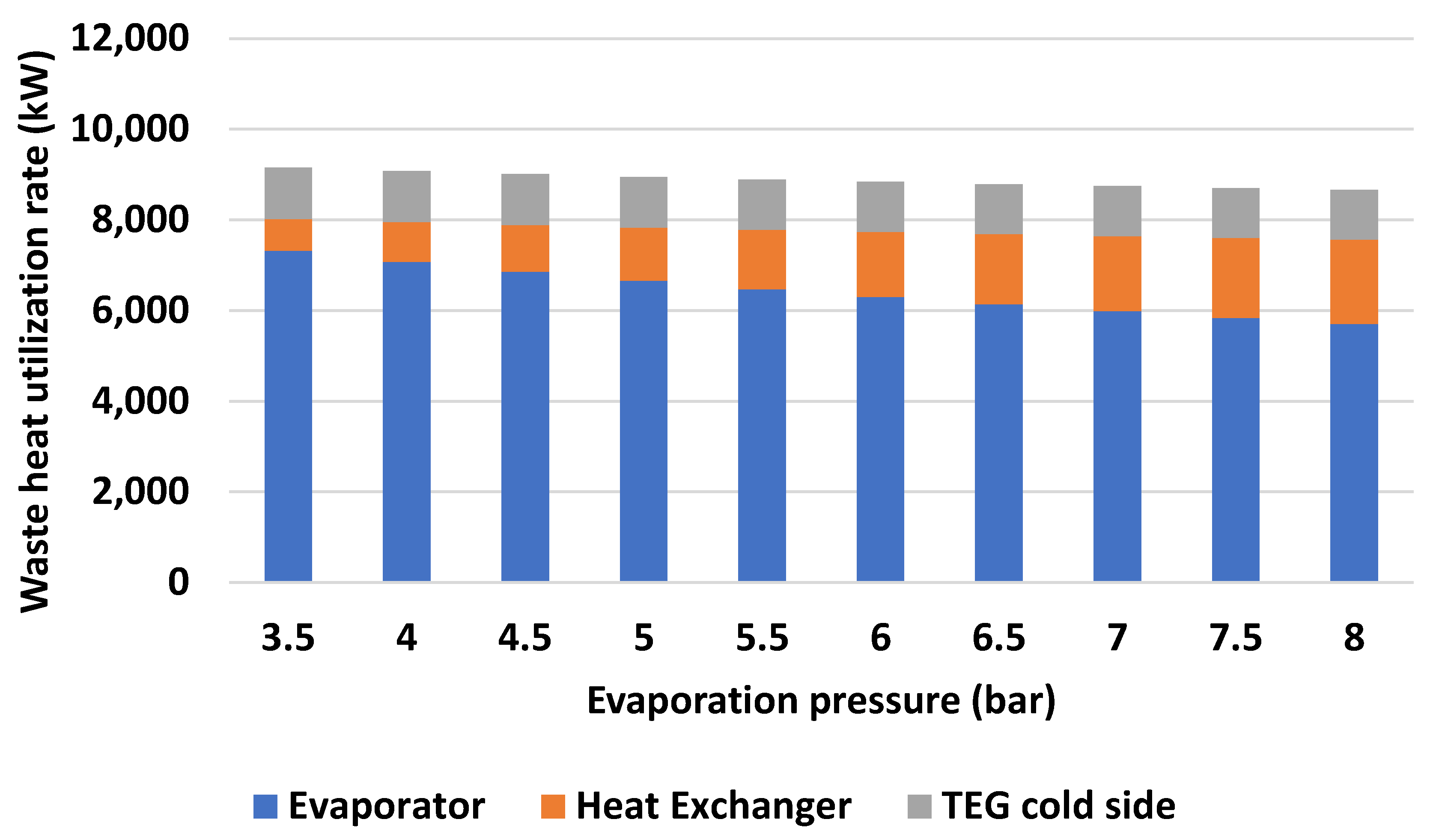
  • The total WH utilization rate of the TEG-ORC system was found to be slightly affected by the evaporation pressure, decreasing in value from 9151 kW at 3.5 bar to around 8658 kW at 8 bar. Furthermore, the evaporator’s WH consumption rate contributes the most, accounting for between 65 and 80% of the entire WH rate.
  • The results show that the energy efficiency of the TEG unit is 6.9% at different evaporation pressures while the efficiency of the ORC increases gradually from 12.3% at 3.5 bar to 17.3% at 8 bar. Additionally, the TEG-ORC system’s efficiency rises gradually, rising from 13.3% at 3.5 bar to 18.3% at 8 bar.
  • Furthermore, the pump power increases from 6.7 to 16.4 kW while the expander’s power output increases from 990 to 1328 kW when the evaporation pressure rises from 3.5 to 8 bar, respectively. Also, the TEG’s output power varies between 75 and 78 kW depending on the evaporation pressure. Therefore, the power output from the TEG-ORC system increases by 30.5% when the evaporation pressure rises from 3.5 to 8 bar.
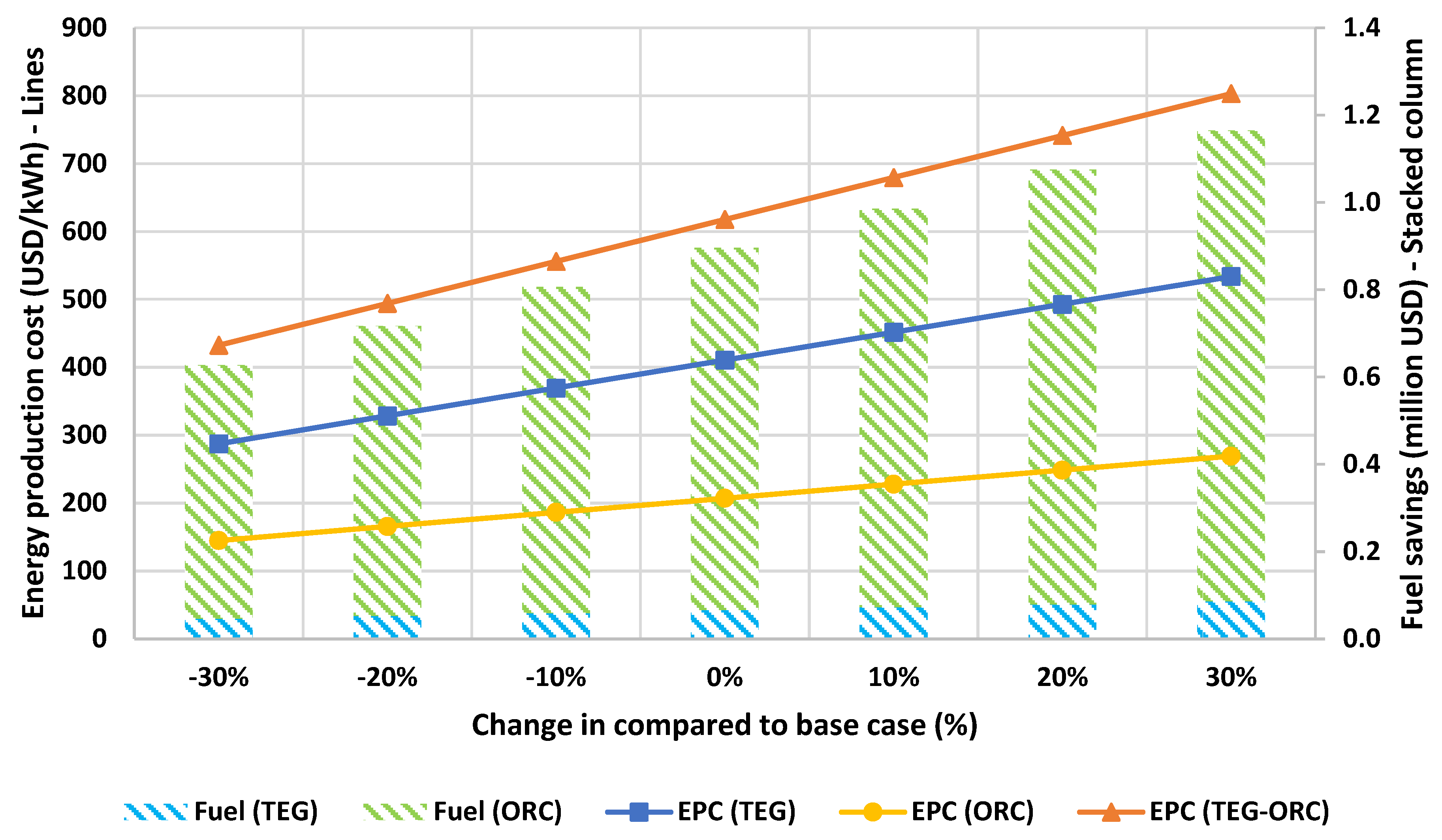
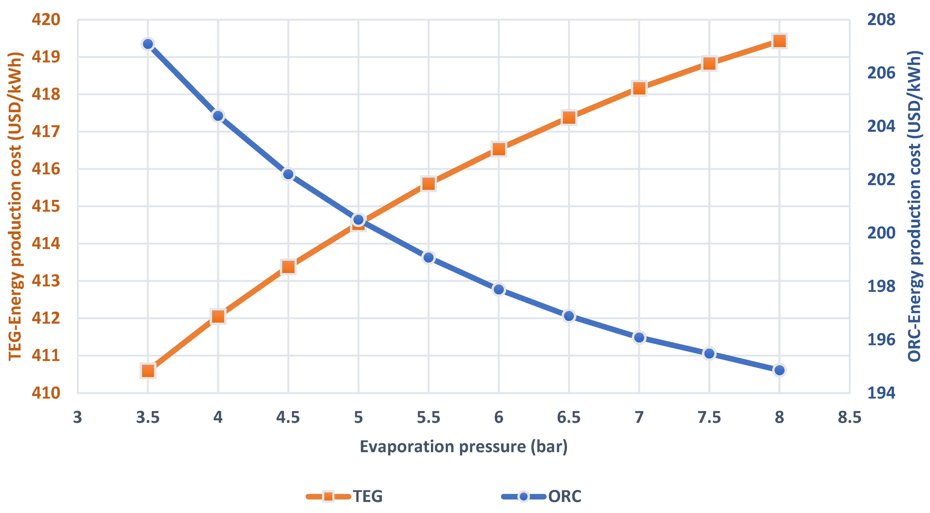
  • The EPC of the TEG system is 411 USD/kWh at 3.5 bar and rises to 419 USD/kWh at 8 bar, indicating a modest increase, while the EPC of ORC system reduces from 207 USD/kWh at 3.5 bar to 195 USD/kWh at 8 bar. Therefore, the EPC of the combined system is 618 USD/kWh and 614 USD/kWh at the lowest and maximum evaporation pressure, respectively. The sensitivity analysis with emphasis on the system component cost shows that the EPC increases to 803 USD/kWh at 3.5 bar as evaporation pressure when the cost of system components increases by 30%.
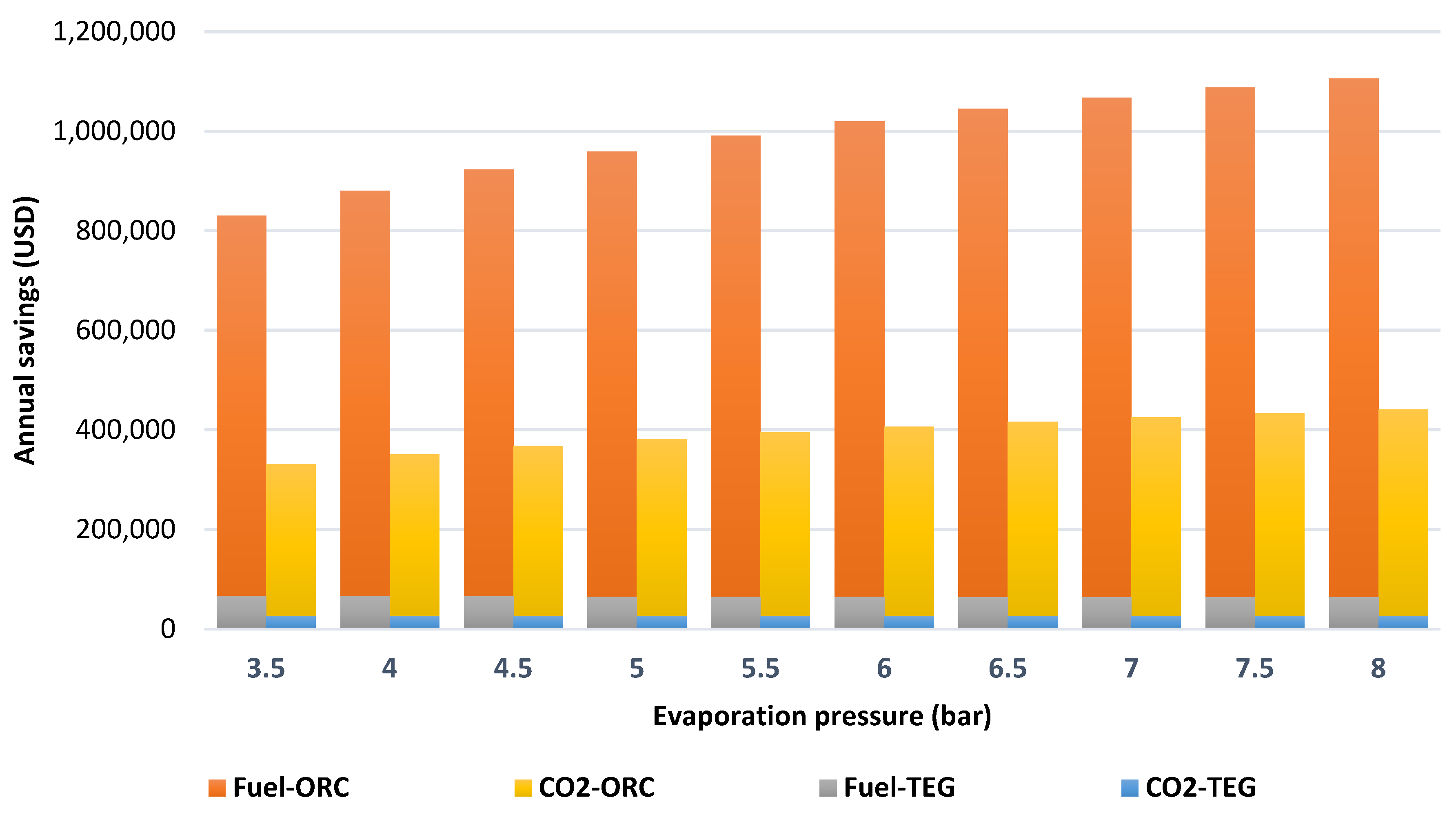
  • Fuel costs and CO2 tax expenses might be reduced by up to 1.169 million USD/year and 0.47 million USD/year, respectively, using the combined TEG-ORC system. Moreover, the sensitivity analysis results indicate that an increase in fuel cost by 30% leads to an increase in savings in fuel expenses up to 1.17 million USD/year.
It is strongly encouraged that subsequent studies in the future will explore how the integrated TEG-ORC system influences IMO metrics like CII, and EEXI in order to guarantee adherence to regulations and the achievement of IMO goals. Furthermore, it is suggested that future performance evaluations be broadened to consider additional factors such as TEG material factor and hot source quantity/quality.

Funding

This research received no external funding.

Data Availability Statement

Data are contained within the article.

Conflicts of Interest

The author declares no conflicts of interest.

Nomenclature

Abbreviations
EESEngineering Equation Solver
GHGGreenhouse gases
IEEIsobaric Expansion Engines
IMOInternational Maritime Organization
KCKalina cycle
OFCOrganic flash cycle
ORCOrganic Rankine cycle
PTGPower turbine generator
RCSReduced cargo space
SMCRSpecified maximum continuous rating
STGSteam turbine generator
SRCSteam Rankine cycle
TEGThermoelectric generator
TEUTwenty-foot equivalent unit
WHWaste heat
WHRWaste heat recovery
Variables
ASAnnual savings (USD)
CCost (USD)
CACapital cost (USD)
EPCEnergy production cost (USD/kWh)
hEnthalpy (kJ/kg)
iInterest rate (−)
KCost coefficient (−)
mMass flow rate (kg/s)
NNumber of investment years (years)
QWaste heat rate (kJ/s)
SFCSpecific fuel consumption (kg/kWh)
T Operational time [hour]
WPower (kW)
ZArea (m2)
η Efficiency (%)
Subscripts
annAnnual
condCondenser
cwCooling water
DGDiesel generator
evapEvaporator
exhExhaust gases
expExpander
jwJacket cooling water
ofOrganic fluid
O&MOperation and maintenance
puPump
saScavenge air

References

  1. IMO. Fourth IMO Greenhouse Gas Study; International Maritime Organization: London, UK, 2021; pp. 197–212. [Google Scholar]
  2. Elkafas, A.G. Advanced Operational Measure for Reducing Fuel Consumption Onboard Ships. Environ. Sci. Pollut. Res. 2022, 29, 90509–90519. [Google Scholar] [CrossRef] [PubMed]
  3. Joung, T.-H.; Kang, S.-G.; Lee, J.-K.; Ahn, J. The IMO Initial Strategy for Reducing Greenhouse Gas(GHG) Emissions, and Its Follow-up Actions towards 2050. J. Int. Marit. Saf. Environ. Aff. Shipp. 2020, 4, 1–7. [Google Scholar] [CrossRef]
  4. Mallouppas, G.; Yfantis, E.A. Decarbonization in Shipping Industry: A Review of Research, Technology Development, and Innovation Proposals. J. Mar. Sci. Eng. 2021, 9, 415. [Google Scholar] [CrossRef]
  5. MAN Diesel & Turbo. Recovery System (WHRS) for reduction of fuel consumption, emissions and EEDI. In Waste Heat; MAN Diesel & Turbo: Augsburg, Germany, 2016. [Google Scholar]
  6. Singh, D.V.; Pedersen, E. A Review of Waste Heat Recovery Technologies for Maritime Applications. Energy Convers. Manag. 2016, 111, 315–328. [Google Scholar] [CrossRef]
  7. Lampe, J.; Rüde, E.; Papadopoulos, Y.; Kabir, S. Model-Based Assessment of Energy-Efficiency, Dependability, and Cost-Effectiveness of Waste Heat Recovery Systems Onboard Ship. Ocean Eng. 2018, 157, 234–250. [Google Scholar] [CrossRef]
  8. Ouyang, T.; Wang, Z.; Zhao, Z.; Lu, J.; Zhang, M. An Advanced Marine Engine Waste Heat Utilization Scheme: Electricity-Cooling Cogeneration System Integrated with Heat Storage Device. Energy Convers. Manag. 2021, 235, 113955. [Google Scholar] [CrossRef]
  9. Díaz-Secades, L.A.; González, R.; Rivera, N.; Montañés, E.; Quevedo, J.R. Waste Heat Recovery System for Marine Engines Optimized through a Preference Learning Rank Function Embedded into a Bayesian Optimizer. Ocean Eng. 2023, 281, 114747. [Google Scholar] [CrossRef]
  10. Ononogbo, C.; Nwosu, E.C.; Nwakuba, N.R.; Nwaji, G.N.; Nwufo, O.C.; Chukwuezie, O.C.; Chukwu, M.M.; Anyanwu, E.E. Opportunities of Waste Heat Recovery from Various Sources: Review of Technologies and Implementation. Heliyon 2023, 9, e13590. [Google Scholar] [CrossRef]
  11. Fisher, R.; Niknam, P.; Ciappi, L.; Sciacovelli, A. Innovative waste heat valorisation technologies for zero-carbon ships—A review. In Proceedings of the 36th International Conference on Efficiency, Cost, Optimization, Simulation and Environmental Impact of Energy Systems (ECOS 2023), Las Palmas de Gran Canaria, Spain, 25–30 June 2023; pp. 2786–2797. [Google Scholar]
  12. Olaniyi, E.O.; Prause, G. Investment Analysis of Waste Heat Recovery System Installations on Ships’ Engines. J. Mar. Sci. Eng. 2020, 8, 811. [Google Scholar] [CrossRef]
  13. Senary, K.; Tawfik, A.; Hegazy, E.; Ali, A. Development of a Waste Heat Recovery System Onboard LNG Carrier to Meet IMO Regulations. Alex. Eng. J. 2016, 55, 1951–1960. [Google Scholar] [CrossRef]
  14. Kristiansen, N.R.; Nielsen, H.K. Potential for Usage of Thermoelectric Generators on Ships. J. Electron. Mater. 2010, 39, 1746–1749. [Google Scholar] [CrossRef]
  15. Lion, S.; Taccani, R.; Vlaskos, I.; Scrocco, P.; Vouvakos, X.; Kaiktsis, L. Thermodynamic Analysis of Waste Heat Recovery Using Organic Rankine Cycle (ORC) for a Two-Stroke Low Speed Marine Diesel Engine in IMO Tier II and Tier III Operation. Energy 2019, 183, 48–60. [Google Scholar] [CrossRef]
  16. Mohammadkhani, F.; Yari, M.; Ranjbar, F. A Zero-Dimensional Model for Simulation of a Diesel Engine and Exergoeconomic Analysis of Waste Heat Recovery from Its Exhaust and Coolant Employing a High-Temperature Kalina Cycle. Energy Convers. Manag. 2019, 198, 111782. [Google Scholar] [CrossRef]
  17. Roosjen, S.; Glushenkov, M.; Kronberg, A.; Kersten, S. Waste Heat Recovery Systems with Isobaric Expansion Technology Using Pure and Mixed Working Fluids. Energies 2022, 15, 5265. [Google Scholar] [CrossRef]
  18. Tadros, M.; Ventura, M.; Soares, C.G. Review of Current Regulations, Available Technologies, and Future Trends in the Green Shipping Industry. Ocean. Eng. 2023, 280, 114670. [Google Scholar] [CrossRef]
  19. Casisi, M.; Pinamonti, P.; Reini, M. Increasing the Energy Efficiency of an Internal Combustion Engine for Ship Propulsion with Bottom ORCS. Appl. Sci. 2020, 10, 6919. [Google Scholar] [CrossRef]
  20. Mondejar, M.E.; Ahlgren, F.; Thern, M.; Genrup, M. Quasi-Steady State Simulation of an Organic Rankine Cycle for Waste Heat Recovery in a Passenger Vessel. Appl. Energy 2017, 185, 1324–1335. [Google Scholar] [CrossRef]
  21. Wieland, C.; Schifflechner, C.; Braimakis, K.; Kaufmann, F.; Dawo, F.; Karellas, S.; Besagni, G.; Markides, C.N. Innovations for Organic Rankine Cycle Power Systems: Current Trends and Future Perspectives. Appl. Therm. Eng. 2023, 225, 120201. [Google Scholar] [CrossRef]
  22. Larsen, U.; Sigthorsson, O.; Haglind, F. A Comparison of Advanced Heat Recovery Power Cycles in a Combined Cycle for Large Ships. Energy 2014, 74, 260–268. [Google Scholar] [CrossRef]
  23. Baldi, F.; Larsen, U.; Gabrielii, C. Comparison of Different Procedures for the Optimisation of a Combined Diesel Engine and Organic Rankine Cycle System Based on Ship Operational Profile. Ocean Eng. 2015, 110, 85–93. [Google Scholar] [CrossRef]
  24. Mondejar, M.E.; Andreasen, J.G.; Pierobon, L.; Larsen, U.; Thern, M.; Haglind, F. A Review of the Use of Organic Rankine Cycle Power Systems for Maritime Applications. Renew. Sustain. Energy Rev. 2018, 91, 126–151. [Google Scholar] [CrossRef]
  25. Chintala, V.; Kumar, S.; Pandey, J.K. A Technical Review on Waste Heat Recovery from Compression Ignition Engines Using Organic Rankine Cycle. Renew. Sustain. Energy Rev. 2018, 81, 493–509. [Google Scholar] [CrossRef]
  26. Champier, D. Thermoelectric Generators: A Review of Applications. Energy Convers. Manag. 2017, 140, 167–181. [Google Scholar] [CrossRef]
  27. Shittu, S.; Li, G.; Zhao, X.; Ma, X. Review of Thermoelectric Geometry and Structure Optimization for Performance Enhancement. Appl. Energy 2020, 268, 115075. [Google Scholar] [CrossRef]
  28. Saha, M.; Tregenza, O.; Twelftree, J.; Hulston, C. A Review of Thermoelectric Generators for Waste Heat Recovery in Marine Applications. Sustain. Energy Technol. Assess. 2023, 59, 103394. [Google Scholar] [CrossRef]
  29. Jia, X.; Fan, S.; Zhang, Z.; Wang, H. Performance Assessment of Thermoelectric Generators with Application on Aerodynamic Heat Recovery. Micromachines 2021, 12, 1399. [Google Scholar] [CrossRef] [PubMed]
  30. Albatati, F.; Attar, A. Analytical and Experimental Study of Thermoelectric Generator (Teg) System for Automotive Exhaust Waste Heat Recovery. Energies 2021, 14, 204. [Google Scholar] [CrossRef]
  31. Von Lukowicz, M.; Abbe, E.; Schmiel, T.; Tajmar, M. Thermoelectric Generators on Satellites—An Approach for Waste Heat Recovery in Space. Energies 2016, 9, 541. [Google Scholar] [CrossRef]
  32. Uyanık, T.; Ejder, E.; Arslanoğlu, Y.; Yalman, Y.; Terriche, Y.; Su, C.L.; Guerrero, J.M. Thermoelectric Generators as an Alternative Energy Source in Shipboard Microgrids. Energies 2022, 15, 4248. [Google Scholar] [CrossRef]
  33. Georgopoulou, C.A.; Dimopoulos, G.G.; Kakalis, N.M.P. A Modular Dynamic Mathematical Model of Thermoelectric Elements for Marine Applications. Energy 2016, 94, 13–28. [Google Scholar] [CrossRef]
  34. Ji, D.; Tseng, K.J.; Wei, Z.; Zheng, Y.; Romagnoli, A. A Simulation Study on a Thermoelectric Generator for Waste Heat Recovery from a Marine Engine. J. Electron. Mater. 2017, 46, 2908–2914. [Google Scholar] [CrossRef]
  35. Zhu, S.; Zhang, K.; Deng, K. A Review of Waste Heat Recovery from the Marine Engine with Highly Efficient Bottoming Power Cycles. Renew. Sustain. Energy Rev. 2020, 120, 109611. [Google Scholar] [CrossRef]
  36. Elkafas, A.G.; Elgohary, M.M.; Shouman, M.R. Implementation of Liquefied Natural Gas as a Marine Fuel to Reduce the Maritime Industries Climate Impact. Nav. Eng. J. 2022, 134, 125–135. [Google Scholar]
  37. MAN Diesel & Turbo. MAN B&W S90ME-C9.2-TII Project Guide; MAN Diesel & Turbo: Augsburg, Germany, 2012. [Google Scholar]
  38. MAN. CEAS Engine Calculations. Available online: https://www.man-es.com/marine/products/planning-tools-and-downloads/ceas-engine-calculations (accessed on 25 January 2024).
  39. Ziapour, B.M.; Saadat, M.; Palideh, V.; Afzal, S. Power Generation Enhancement in a Salinity-Gradient Solar Pond Power Plant Using Thermoelectric Generator. Energy Convers. Manag. 2017, 136, 283–293. [Google Scholar] [CrossRef]
  40. Zare, V.; Palideh, V. Employing Thermoelectric Generator for Power Generation Enhancement in a Kalina Cycle Driven by Low-Grade Geothermal Energy. Appl. Therm. Eng. 2018, 130, 418–428. [Google Scholar] [CrossRef]
  41. Aliahmadi, M.; Moosavi, A.; Sadrhosseini, H. Multi-Objective Optimization of Regenerative ORC System Integrated with Thermoelectric Generators for Low-Temperature Waste Heat Recovery. Energy Rep. 2021, 7, 300–313. [Google Scholar] [CrossRef]
  42. Tian, H.; Shu, G.; Wei, H.; Liang, X.; Liu, L. Fluids and Parameters Optimization for the Organic Rankine Cycles (ORCs) Used in Exhaust Heat Recovery of Internal Combustion Engine (ICE). Energy 2012, 47, 125–136. [Google Scholar] [CrossRef]
  43. Larsen, U.; Pierobon, L.; Haglind, F.; Gabrielii, C. Design and Optimisation of Organic Rankine Cycles for Waste Heat Recovery in Marine Applications Using the Principles of Natural Selection. Energy 2013, 55, 803–812. [Google Scholar] [CrossRef]
  44. Lemmon, E.W.; Span, R. Short Fundamental Equations of State for 20 Industrial Fluids. J. Chem. Eng. Data 2006, 51, 785–850. [Google Scholar] [CrossRef]
  45. Kamei, A.; Beyerlein, S.W.; Jacobsen, R.T. Application of Nonlinear Regression in the Development of a Wide Range Formulation for HCFC-22. Int. J. Thermophys. 1995, 16, 1155–1164. [Google Scholar] [CrossRef]
  46. Elkafas, A.G.; Rivarolo, M.; Massardo, A.F. Assessment of Alternative Marine Fuels from Environmental, Technical, and Economic Perspectives Onboard Ultra Large Container Ship. Trans. R. Inst. Nav. Archit. Int. J. Marit. Eng. 2022, 164, 125–134. [Google Scholar] [CrossRef]
  47. Yang, M.-H. Payback Period Investigation of the Organic Rankine Cycle with Mixed Working Fluids to Recover Waste Heat from the Exhaust Gas of a Large Marine Diesel Engine. Energy Convers. Manag. 2018, 162, 189–202. [Google Scholar] [CrossRef]
  48. UNCTAD. Review of Maritime Transport 2022; United Nations: Manhatten, YT, USA, 2022; ISBN 9789211130737. [Google Scholar]
  49. Korberg, A.D.; Brynolf, S.; Grahn, M.; Skov, I.R. Techno-Economic Assessment of Advanced Fuels and Propulsion Systems in Future Fossil-Free Ships. Renew. Sustain. Energy Rev. 2021, 142, 110861. [Google Scholar] [CrossRef]
  50. Gholamian, E.; Habibollahzade, A.; Zare, V. Development and Multi-Objective Optimization of Geothermal-Based Organic Rankine Cycle Integrated with Thermoelectric Generator and Proton Exchange Membrane Electrolyzer for Power and Hydrogen Production. Energy Convers. Manag. 2018, 174, 112–125. [Google Scholar] [CrossRef]
  51. Ng, C.; Tam, I.C.K.; Wetenhall, B. Waste Heat Source Profiles for Marine Application of Organic Rankine Cycle. J. Mar. Sci. Eng. 2022, 10, 1122. [Google Scholar] [CrossRef]
  52. WorldBank. State and Trends of Carbon. In Pricing 2023; World Bank: Washington, DC, USA, 2023; ISBN 9781464820069. [Google Scholar]
  53. Pan, L.; Wang, H.; Shi, W. Performance Analysis in Near-Critical Conditions of Organic Rankine Cycle. Energy 2012, 37, 281–286. [Google Scholar] [CrossRef]
  54. Fernández, F.J.; Prieto, M.M.; Suárez, I. Thermodynamic Analysis of High-Temperature Regenerative Organic Rankine Cycles Using Siloxanes as Working Fluids. Energy 2011, 36, 5239–5249. [Google Scholar] [CrossRef]
  55. Colonna, P.; Casati, E.; Trapp, C.; Mathijssen, T.; Larjola, J.; Turunen-Saaresti, T.; Uusitalo, A. Organic Rankine Cycle Power Systems: From the Concept to Current Technology, Applications, and an Outlook to the Future. J. Eng. Gas. Turbine Power 2015, 137, 100801. [Google Scholar] [CrossRef]
  56. Spadacini, C.; Centemeri, L.; Xodo, L.; Astolfi, M.; Romano, M.; Macchi, E. A New configuration for organic rankine cycle power systems. In Proceedings of the Delft ORC 2011, Delft, The Netherlands, 29 August–1 September 2011. [Google Scholar]
  57. AlfaLaval E-PowerPack. Available online: https://www.alfalaval.com/products/heat-transfer/power-generator/e-powerpack/ (accessed on 17 May 2023).
  58. DNV. Alternative Fuels Insights (AFI). Available online: https://www.dnv.com/services/alternative-fuels-insights-afi--128171 (accessed on 14 January 2024).
Figure 1. Fuel consumption and exhaust gas data at different engine loads [38].
Processes 12 00355 g001
Figure 2. Sankey diagram of the engine MAN 8S90ME-C at a power of 32.7 MW; the values of heat and power are expressed in kW [37,38].
Processes 12 00355 g002
Figure 3. Description of the TEG-ORC combined system integrating with the ship’s main engine.
Processes 12 00355 g003
Figure 4. The effect of different evaporation pressure on waste heat utilization rate.
Processes 12 00355 g004
Figure 5. Evaporation pressure versus the net output power and system efficiency.
Processes 12 00355 g005
Figure 6. Weight and volume of TEG-ORC system at different evaporation pressure.
Processes 12 00355 g006
Figure 7. Comparison of energy production cost of TEG and ORC systems under different evaporation pressure.
Processes 12 00355 g007
Figure 8. Annual fuel cost savings and CO2 tax expenses resulting from installing TEG and ORC systems on board a container ship.
Processes 12 00355 g008
Figure 9. Results of sensitivity analysis with emphasis on fuel cost and system cost.
Processes 12 00355 g009
Table 1. Waste heat to power technologies [11,18].
TechnologyTemperature RangeRecovery SourceCapacity (kW)Efficiency (η)
Organic Rankine cycle (ORC)Low–MediumExhaust gas–Jacket water–charge air10–10,0005–25%
Isobaric Expansion Engines (IEEs)LowJacket water/Charge air/Exhaust gas1–10001–14%
Turbo compoundingMedium–HighExhaust Gas500–10,0003–15%
Steam Rankine cycles (SRC)Medium–HighExhaust Gas500–20003–20%
Thermoelectric generation (TEG)Medium–HighExhaust gas–Jacket water1–801–20%
Organic flash cycles (OFCs)Low–MediumExhaust gas–Jacket water5–2005–20%
Kalina cycles (KCs)Low–MediumExhaust gas–Jacket water20–100,0007.5–35%
Table 2. Main specifications of marine diesel engine [37].
SpecificationMAN 8S90ME-C
Main engine typeTwo-stroke diesel engine
Number of cylinders8
NOx emission complianceTier III
Engine speed (rpm)84
Specified maximum continuous rating—SMCR (MW)42.5
SMCR speed (rpm)84
Specific fuel consumption at MCR (g/kWh)166.1
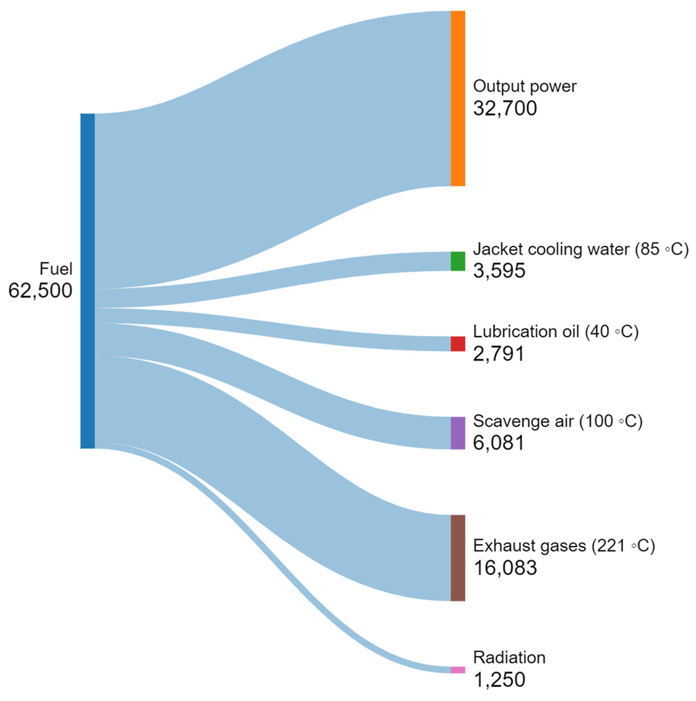
Ship power demand at actual condition (MW)32.7
Table 3. The values of input data and parameters [38,41].
ParameterValueParameterValue
m e x h  (kg/s) 52.6 η e x p 85%
T e x h  (°C) 221 T a p p  (°C)65
T j w  (°C) 85 Z T M 0.8
T s a  (°C) 100 T p p 1  (°C)5
η p u 90% T p p 2  (°C)5
Table 4. Equations for energy performance indicators.
SystemNet Power (kW)Energy Efficiency
ORC W O R C = W E x p W p u η O R C = W E x p W p u Q p r e + Q e v a p
TEG W T E G = η T E G × Q C η T E G = ( 1 T L T H ) 1 + Z T M 1 1 + Z T M + T L T H
TEG-ORC W T E G O R C = W E x p + W T E G W p u η T E G O R C = W E x p + W T E G W p u Q p r e + Q e v a p + Q C
Table 5. Values of different correction coefficients [51].
CoefficientTEG Unit/PreheaterPumpEvaporatorCondenser
K12.84833.57933.21383.2138
K20.21680.32080.26880.2688
K30.079610.02850.079610.07961
C1−0.0650.1682−0.06499−0.06499
C20.050250.34770.050250.05025
C30.014740.48410.014740.01474
B11.81.81.81.8
B21.51.511.51.5
FM1.251.81.251.25
Disclaimer/Publisher’s Note: The statements, opinions and data contained in all publications are solely those of the individual author(s) and contributor(s) and not of MDPI and/or the editor(s). MDPI and/or the editor(s) disclaim responsibility for any injury to people or property resulting from any ideas, methods, instructions or products referred to in the content.

