1. Introduction
Energy separation refers to the phenomenon whereby a system spontaneously separates into a part of the high-temperature zone and a part of the low-temperature zone in the absence of external work or heat conduction. Since the French engineer Ranque first observed the energy separation phenomenon in the vortex tube in the 1930s [
1], researchers have observed the energy separation phenomenon in other flow conditions, such as free jet, vortex, impinging jet, and flow around circular cylinder, and studied its laws. Currently, the research on energy separation [
2,
3,
4,
5,
6,
7] mainly focuses on the technical application level of vortex tubes and vortex plates based on the Ranque–Hilsch effect, which belongs to the engineering thermodynamics problem. Regarding the study of the operation mechanism of energy separation in the field of fluid mechanics such as free jet, impinging jet, blunt-body flow, etc., researchers have made some experimental and theoretical in-depth studies on this, but they also mainly focus on the single jet. Research on the combined jet is few and far between. However, multiple jets are also encountered in practical engineering applications, such as multiple jets impinging on downstream water cushion ponds in high head relief projects, and impinging jet on the fuselage and the ground during take-off and landing of aircraft in vertical take-off (landing) in aerospace projects. Therefore, understanding and mastering the characteristics of multiple jets are of great significance in guiding the solution of practical engineering problems.
In the 1940s, Eckert and Drewitz [
8] discovered the existence of energy separation in the boundary layer by analyzing the temperature field in the air boundary layer along the direction of the flow pressure gradient. Subsequently, Eckert and Weise [
9] found that energy separation also exists in turbulent vortex streets when they measured the recovery temperature of a high-velocity gas stream around a cylindrical flow. Goldstein et al. [
10,
11] first observed energy separation in shock jets in 1986 and 1990. The experimental results show that when the experimental nozzle and the adiabatic plate are not far away from each other, a significant minimum value in the radial recovery temperature distribution occurs. They suggest that this is due to the energy separation effect produced by the circular vortex motion in the jet. Another study [
10,
11,
12,
13] measured the temperature distribution of the flow field in free jets, confirming that both Reynolds number and acoustic excitation can enhance the energy separation effect within a certain range. Han [
14] experimentally measured the instantaneous total temperature and velocity distributions of free jets under different Reynolds numbers and different acoustic excitation conditions. The results not only led to similar conclusions to those of the previous authors, but also showed there is a certain influence of Reynolds number on the energy separation phenomenon—the larger the Reynolds number is, the more obvious the energy separation phenomenon is—and also revealed that acoustic excitation enhances the process of the energy separation effect by influencing the vortex pair fusion motion. Fox and Kurosaka [
15] were the first to investigate the energy separation phenomenon in supersonic jets. They experimentally measured the total temperature distribution of a free jet from subsonic to supersonic conditions, and found that when the speed of sound reaches supersonic, there are more low values in the temperature distribution, which indicates that the energy separation of supersonic free jet is more obvious. Leontiev et al. [
16] experimentally investigated the heat transfer phenomena within two coaxial pipes, and the data verified that the energy separation effect of the compressible boundary layer enhanced the heat transfer process between the two pipes. Through these experiments, people have discovered, recognized, and tried to explain the generation mechanism of energy separation phenomenon under different flow conditions step by step, which has provided significant enlightenment and research direction for subsequent research.
In addition to experimental studies, numerical simulations provide researchers with a more intuitive and effective way to study energy separation effects. Fox and Kurosaka [
17] numerically simulated the energy separation in free jets and impinging jets under inviscid and non-conducting conditions. The authors simulated the energy separation in free jets under different Mach number conditions. The simulation results are in good agreement with the experimentally obtained data, clearly indicating the existence of energy separation phenomena, and the process of vortex twinning was found to enhance the total temperature distribution. Han et al. [
18] numerically simulated the energy separation of two parallel jets to obtain the distribution of instantaneous velocity, pressure, and temperature in a two-dimensional planar shear layer flow field, and the results can clearly show the energy separation effect. They found that the vortex development is accelerated and the energy separation is enhanced with the increase in the Reynolds number.
Scholars have carried out a large number of experimental and numerical simulation studies on the energy separation phenomenon in the field of fluids, but most of the numerical simulations for free jets are focused on single jets at lower Reynolds numbers and with less consideration of viscous effects. However, at lower Reynolds number conditions, the effect of viscous shear on energy separation cannot be neglected. In this paper, two parallel air free jets with different velocities are taken as the object of study to numerically simulate the energy separation phenomenon of the free jet when the inlet velocities are both subsonic. We study the effect of higher Reynolds number on its specificity by taking into account the viscous and thermal conductivity conditions. Adopting the dimensionless turbulence control equations, and on the basis of the previous theoretical and experimental methods, both theoretical analysis and numerical simulation are carried out to verify the existence of the free jet energy separation phenomenon in the subsonic range and the influence of high Reynolds number on the energy separation, and we investigate the formation mechanism of the energy separation of the two parallel free jets and the flow characteristics of the dual jet.
2. Theoretical Analyses
2.1. Analysis of the Causes of Energy Separation
To date, researchers have observed energy segregation under many flow conditions and generally agree with the formation mechanism proposed by Eckert [
19]. Assuming a constant specific heat capacity of the fluid to its surroundings, the total energy conservation equation is as follows:
The left side of the equation represents the change in total fluid energy along its pathline; the first term on the right-hand side of the equation is the hydrostatic pressure fluctuation at a given point; k is fluid thermal conductivity; the second and third terms on the right-hand side of the equation represent the energy transfer resulting from heat transfer and viscous shear work.
For steady state boundary layer flow, Equation (1) can be simplified as follows:
This equation implies that the total temperature can be varied along the streamline by heat transfer or viscous work. The energy separation in the boundary layer flow is caused by an imbalance between these two terms. When the Prandtl number () of a fluid is less than unity including air, heat transfer is greater than viscous work. As a result, the total temperature of the interior region adjacent to the insulated wall will be less than the total temperature of the exterior region.
For unsteady flow without heat transfer and neglecting viscous effects, the second and third terms of Equation (1) are negligible and the conservation equation can be simplified as follows.
In Equation (3), the total fluid temperature fluctuation is only related to the hydrostatic pressure change, and the hydrostatic pressure change generally occurs together with the vortex motion, so that for free jets at subsonic speeds, the energy separation of the free jet is more caused by the pressure fluctuation accompanying the vortex motion when the consideration of the viscous force and the heat conduction effect is neglected.
Since energy separation in boundary layer flows is related to viscous work and heat transfer, entropy always increases due to the irreversibility of the fluid. Therefore, it is reasonable to use the second law of thermodynamics to explain energy separation. Consider the energy separation of inviscid and non-conducting ideal gases with constant properties. The equation for the conservation of total energy expressed in terms of total temperature can be rewritten in total form as follows.
The total enthalpy,
can be expressed in terms of static melt (
) and velocity (
):
After inserting Equation (5) into Equation (4), the total energy conservation can be simplified as follows:
Based on the relationship between entropy and enthalpy, the enthalpy can rewrite melting in terms of entropy and pressure.
Assuming that the gas is a non-viscous, non-conducting fluid, the momentum conservation equation can be simplified to the following Euler equation:
Combining Equations (7) and (8) with Equation (6) results in the following:
Move the pressure gradient term to the right-hand side of Equation (9):
The right-hand side of Equation (10) is defined in the same way as the material derivative of pressure, and thus yields the following:
Equation (8) can be simplified as follows:
This means that the entropy of the fluid remains constant along its path. Thus, the energy separation of an ideal gas is an isentropic process and follows the second law of thermodynamics.
2.2. Numerical Perturbation Stability Analysis
In order to simulate the experimental flow conditions, small disturbances were introduced in the inlet plane. The instability of incompressible mixed layers to small perturbations belongs to the Kelvin–Helmholtz instability. The perturbations were obtained from the stability analysis of the inviscid flow, and the most unstable frequency and its two subharmonic frequencies were chosen as the frequencies of the disturbances. The linear stability analysis of the fluid is based on the continuity equation and unsteady N-S equation.
The magnitude of the inlet velocity of the introduced free jet is as follows:
The energy separation phenomenon of the free jet at different velocities is realized by numerical simulation; the energy separation intensity is characterized by a dimensionless energy separation factor as follows:
Most of the energy separation occurs in the shear layer, so depending on the thickness of the initial shear layer (
), the relative Reynolds number ∆
Re is defined as follows:
2.3. Computational Domain, Boundary Conditions and Meshing
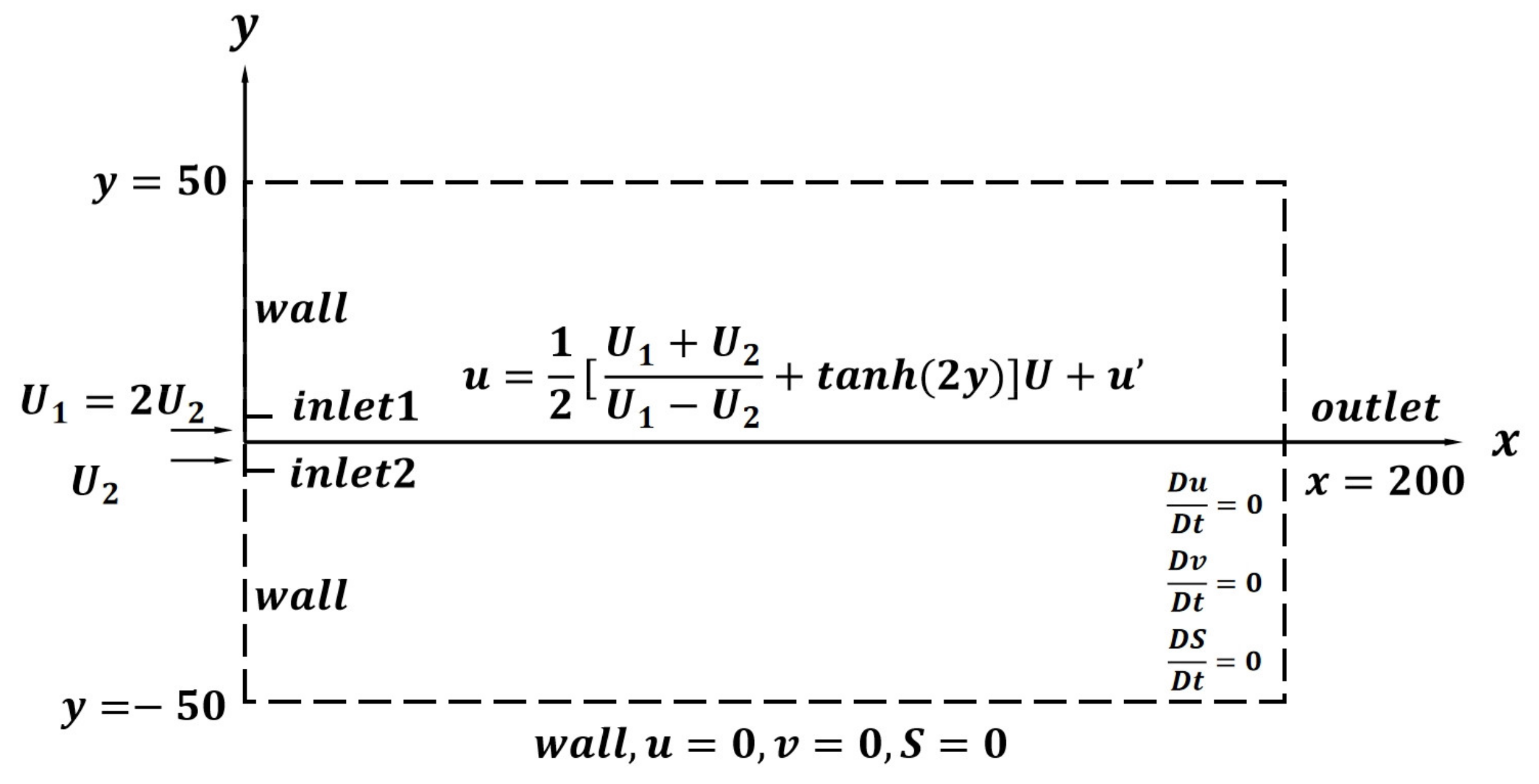
The computational domain is taken as a two-dimensional rectangle with a grid of 200 in x and 100 in y, inlet1 and linlet2 are respectively set up, and the diameters of the two outlets D are both 5 mm. The numerical model and boundary conditions are shown in
Figure 1 and
Table 1. The computational domain is bounded by no-slip wall boundary conditions at both the upper left and lower left ends. In the center are the two velocity inlets of the free jet of air, and the relationship between the upper and lower is maintained at a fixed ratio. The relative Reynolds numbers for each of the five free jet groups are 12,800, 19,200, 25,600, 32,000, 41,500, and 51,100. In this paper, the meshed model is imported into ANSYS FLUENT for the calculation parameters. Simulation of turbulence based on the realizable k-epsilon equations with pressure–velocity coupling, PISO method, discrete method with second-order windward format, and first-order implicit transient solution. The computational model opens the energy equation and does not account for gravity. Unsteady transient flow, and the maximum residual value is 0.001, calculated using a first-order implicit transient solution with a time step of
s. The medium is air and all physical parameters are kept as default. A quadrilateral structured grid is used in gambit. In order to obtain the energy separation effect of the free jet flow field more clearly, the grid encryption process is carried out in the vicinity of the jet boundary layer. The number of grids is obtained to be 67,574.
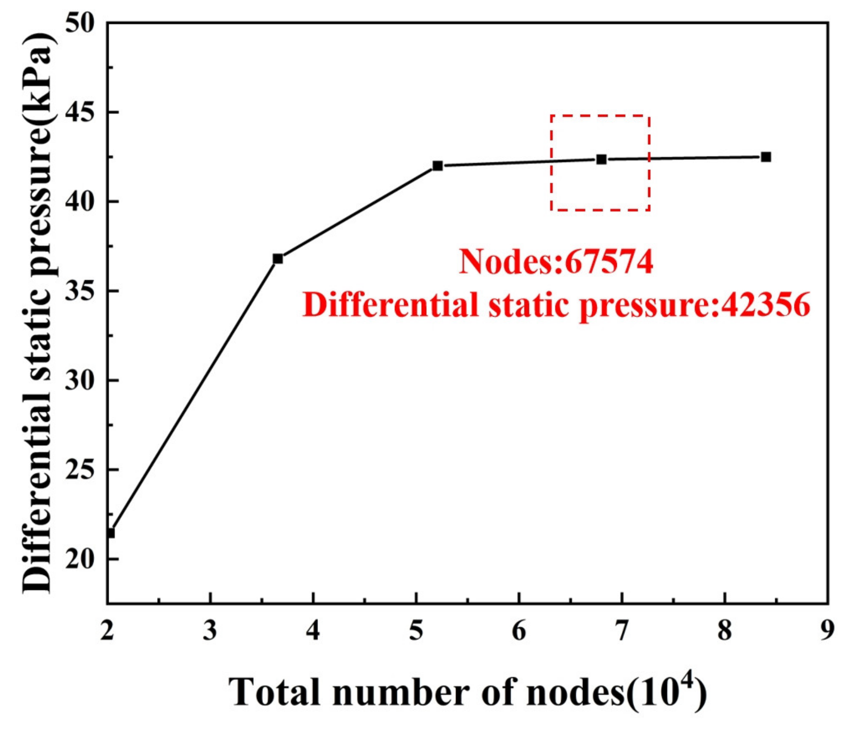
The number of meshes has the potential to affect the accuracy of the calculations, so a mesh-independent analysis is performed. Calculate the static pressure difference in the free jet flow field at t = 240,
, for five different grid accuracies. It can be seen from
Figure 2 that the static differential pressure in the free jet flow field increases with the number of nodes. However, once the number of nodes reaches about 52,300, the tendency to continue to increase is not obvious. That is, the computational method under such conditions has satisfied the grid-independence. For economic considerations, a grid with a node count of 67,574 is chosen in this paper.
3. Analysis of the Results
3.1. Energy Separation Phenomena in Free Jet
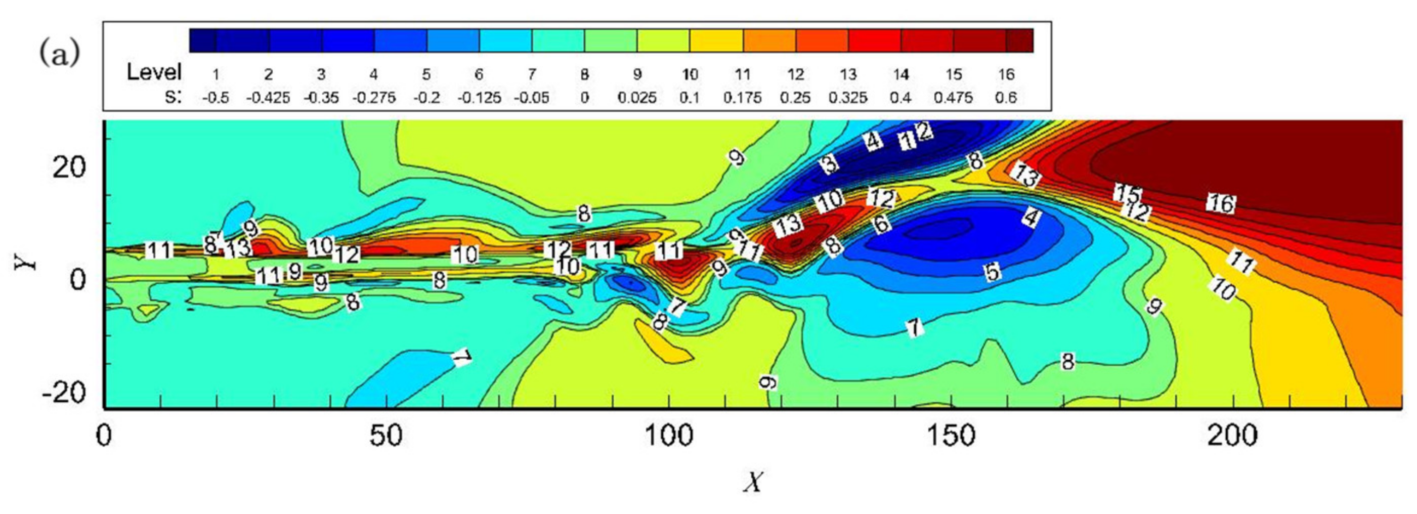
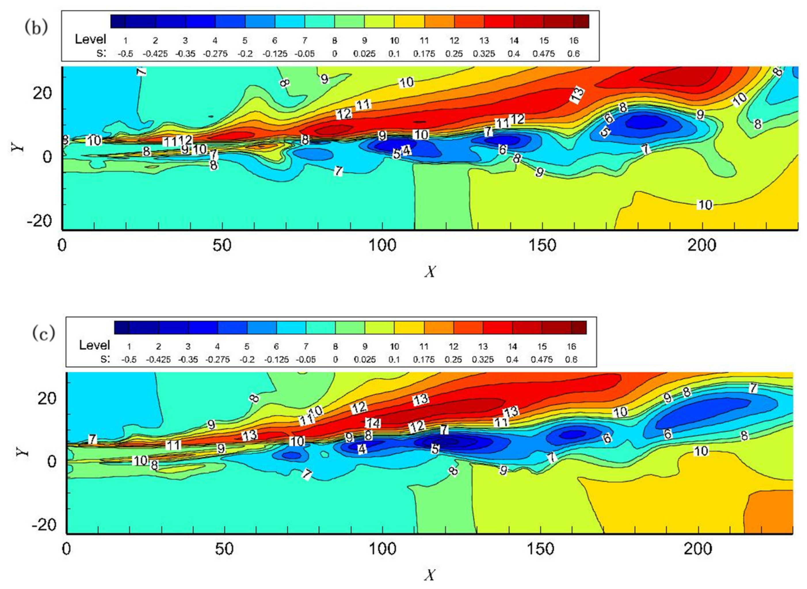
The energy separation factor for two free jets for
at t = 120, t = 240 and t = 270 is shown in
Figure 3. During this time period, the process from the appearance of significant energy separation within the jet field to the stabilization of the separation phenomenon is recorded. The fusion of the two adjacent vortices of the free jet is completed. Alternating high- and low-temperature regions can be seen in the free jet flow field at t = 120. Until t = 270, the energy separation effect tends to stabilize and is clearly divided into upper and lower high- and low-temperature regions. The total temperature separation is evident at x = 50. As the jet gets farther away from the nozzle exit, the energy separation region slowly becomes larger and the energy separation factor slowly increases. The maximum value of the energy separation factor occurs at x about 150 when t = 240, whose value is around 13. Thereafter, the energy separation factor becomes smaller and gradually diverges. The energy separation effect becomes weaker until it disappears. It can be seen that the location of the separation coincides essentially with the location of the vortex center, but the temperature distribution is asymmetric.
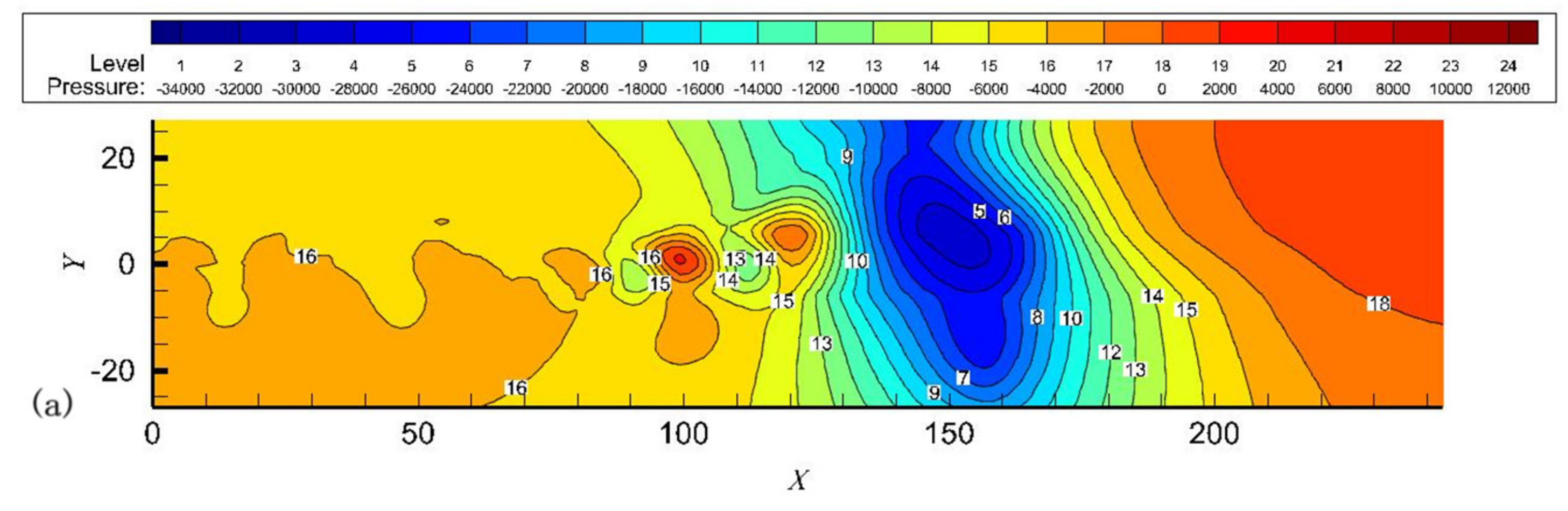
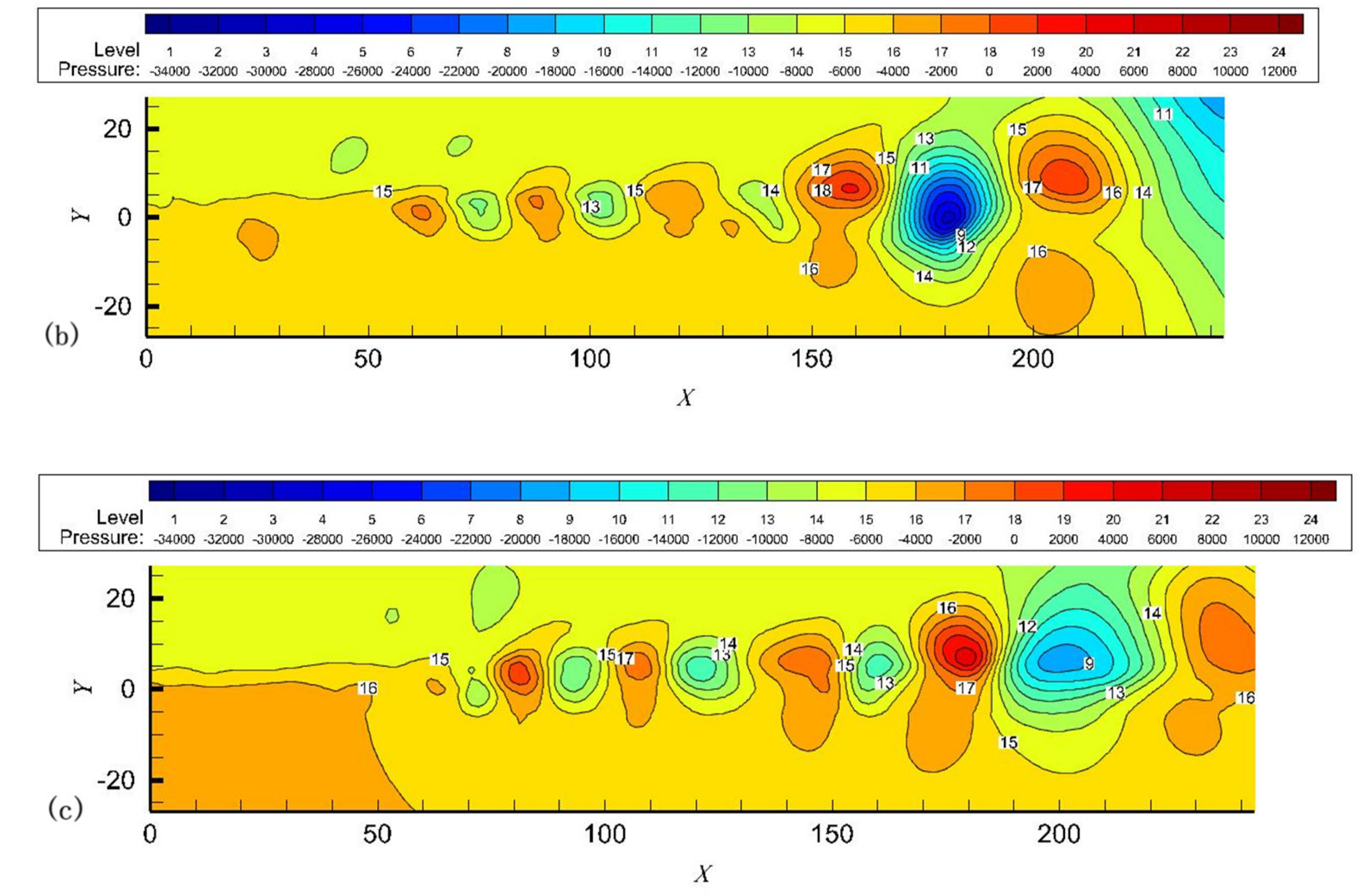
Instantaneous pressure distribution in
Figure 4 clearly shows alternating high- and low-pressure regions within the free jet flow field, with vortices distorting the pressure field. A distinct region of high and low pressure begins to appear near x = 50 from t = 240 to t = 270. When t = 120, the lowest-pressure zone occurs at x = 150 with a pressure rating of about 3. The adjacent high-pressure zone has a rating of about 18. The pressure fluctuation rating of about 15, after which the high- and low-pressure zones slowly become larger; When t = 240, the lowest-pressure zone occurs at x = 180 with a pressure rating of about 6. The adjacent high-pressure zone has a rating of about 18. When t = 270, the lowest-pressure zone occurs at x = 200 with a pressure rating of about 8. The adjacent high-pressure zone has a rating of about 17. The pressure fluctuation rating of about 9. The adjacent high- and low-pressure fluctuations can be seen to be weakened. It can be seen by comparing the energy separation factor cloud diagrams that the high-pressure region produces low temperatures, while the low-pressure region produces high temperatures. As the high- and low-pressure regions become larger and stronger, the corresponding resulting high- and low-temperature regions also become larger and stronger.
In
Figure 5, the process of free-jet vortex generation, coiling and absorption, pairing and fusion, and weakening and disappearance can be clearly seen. In the region close to the inlet, the air free jet path is essentially straight. This region maintains the velocity at the exit of the nozzle. In the boundary layer of the jet at some distance from the nozzle, the high-velocity jet creates a shear layer, which, due to the rapid growth of the natural instability of the shear layer, forms a vortex, which leads to a swirling suction of the surrounding fluid, which draws the surrounding non-spinning fluid into the jet. Vortices continue to be created, expand, and develop, increasing the width of the jet and eventually breaking up into smaller vortices until they disappear.
Comparison of the instantaneous pressure distribution in
Figure 4 shows that there is a low-pressure region near the center of the vortex and a high-pressure region between the vortices. Comparison of the energy separation factors in
Figure 3 shows that the upper half of lower half produces a low-temperature region. These small vortices merge with neighboring vortices. The disturbance applied to the intake tract surface begins to increase and rolls up to form a vortex. The merging vortex moves downstream and combines with another merging vortex. After the vortices merged, the downward slowly weakened and disappeared, causing the pressure fluctuations to taper off and disappear. At the same time, the energy separation effect also weakens until it disappears.
As the vortex moves at a certain speed, so do the aberrations in the pressure field. As a result of the motion, the fluid in the first half of the vortex is subjected to a negative force (work is done on the surrounding fluid), while the fluid in the second half of the vortex is subjected to a positive force (pressure work is done on it by the surrounding fluid). Thus, the fluid loses energy through the first half of the vortex and gains energy through the second half.
Numerical simulation results confirm the significant energy separation effect produced by two parallel air free jets at subsonic speeds. Neglecting the effects of viscous forces and heat transfer, the energy separation of a free jet is generated more by the pressure fluctuations accompanying the vortex motion. In the jet, the second half of the vortex entraps the surrounding fluid and rolls it into the jet and moves with the lower half of the vortex, and the local pressure rises with time. This causes the jet to be compressed, gaining energy from the surrounding fluid and creating a high-temperature zone. In contrast, the first half of the vortex loses some of its energy by carrying out part of the jet, resulting in a pressure loss, thus creating a low-temperature zone. Through this process, the free jet exchanges pressure work with the surrounding fluid resulting in a separation of the total energy of the jet.
3.2. Influence of on the Energy Separation of Free Jet
In order to investigate the influence of the Reynolds number on the free jet energy separation, the distribution of the free jet energy separation factor is compared when
19,200, 25,600, 32,000, 41,500, and 51,100, respectively, and the results are shown in
Figure 6.
Comparison results found that the distribution trend of energy separation factor at different axial positions is essentially the same under the five numbers, indicating that the formation of free jet energy separation phenomenon is essentially the same under the five numbers.
We define the longitudinal distance between the peak and the trough of the energy separation factor as the width of the energy separation region. In the free jet direction from x = 0 to x = 160, as increases from 19,200 to 51,100, it can be seen that the larger , the farther the maximum value of the energy separation factor is from the exit of the jet nozzle, and the wider the width of the energy separation region. This is due to the increased vortex motion and enhanced pressure fluctuations as the inertial forces increase, which play major roles in the free jet energy separation. We note, however, that the situation is slightly different when = 19,200: the maximum energy separation factor value occurs at x = 68.18, whose width of the energy separation region is significantly larger than when = 25,600, reaching 0.2972. This suggests that when the Reynolds number is low, viscous shear plays a non-negligible role in energy separation compared to the pressure fluctuations generated by the vortex and facilitates the energy separation to some extent.
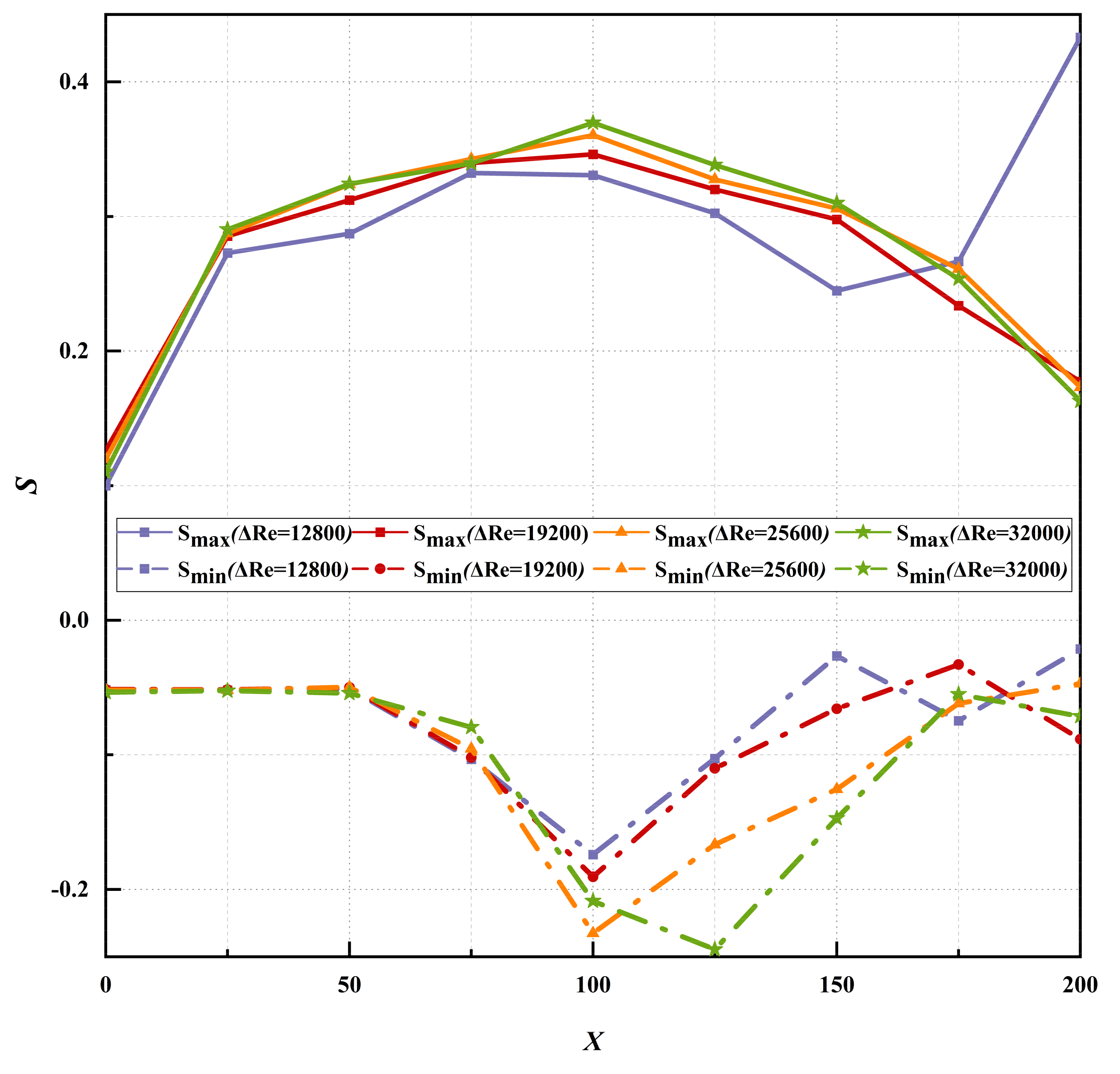
3.3. Streamwise Variation of
The results of the axial variation of the maximum (
) and minimum (
) values of the free jet energy separation factor are shown in
Figure 7. The figure shows more clearly the effect of vortexing on the energy separation compared to when it is closer to the jet axis. It can be found that the trend is basically the same in all cases except when the velocity is small (at
= 25,600), when the viscous shear dominates. When x is in the range of 0 to 25, a sharp increase in the rate of change of
and
is observed for vortex generation, indicating that the closer to the nozzle exit region, the faster the energy separation develops. The results confirm that the energy separation mechanism induced by pressure pulsation during vortex motion transport is much stronger than that induced by shear work and heat transfer imbalance. It is important to note that both the magnitude and amplitude of the change in
is greater than
. It is thought that this difference stems from the different path lines in the upper and lower parts of the clipping layer. This may be due to the three different types of fluid particle paths proposed by Breidenthal [
20].
3.4. Flow Characteristics of Dual-Jet
The dual jets suck and interfere with each other, resulting in the formation of a negative pressure in the area surrounded by the dual jets (inside the cavity). An important feature of two-dimensional parallel dual jets is the presence of a negative-pressure region between the dual jets, which is due to the entrainment of the turbulent jet to the surrounding fluid. As a result, the dual jets are attracted to each other so that the axis of the jets bends and then the dual jets merge into one.
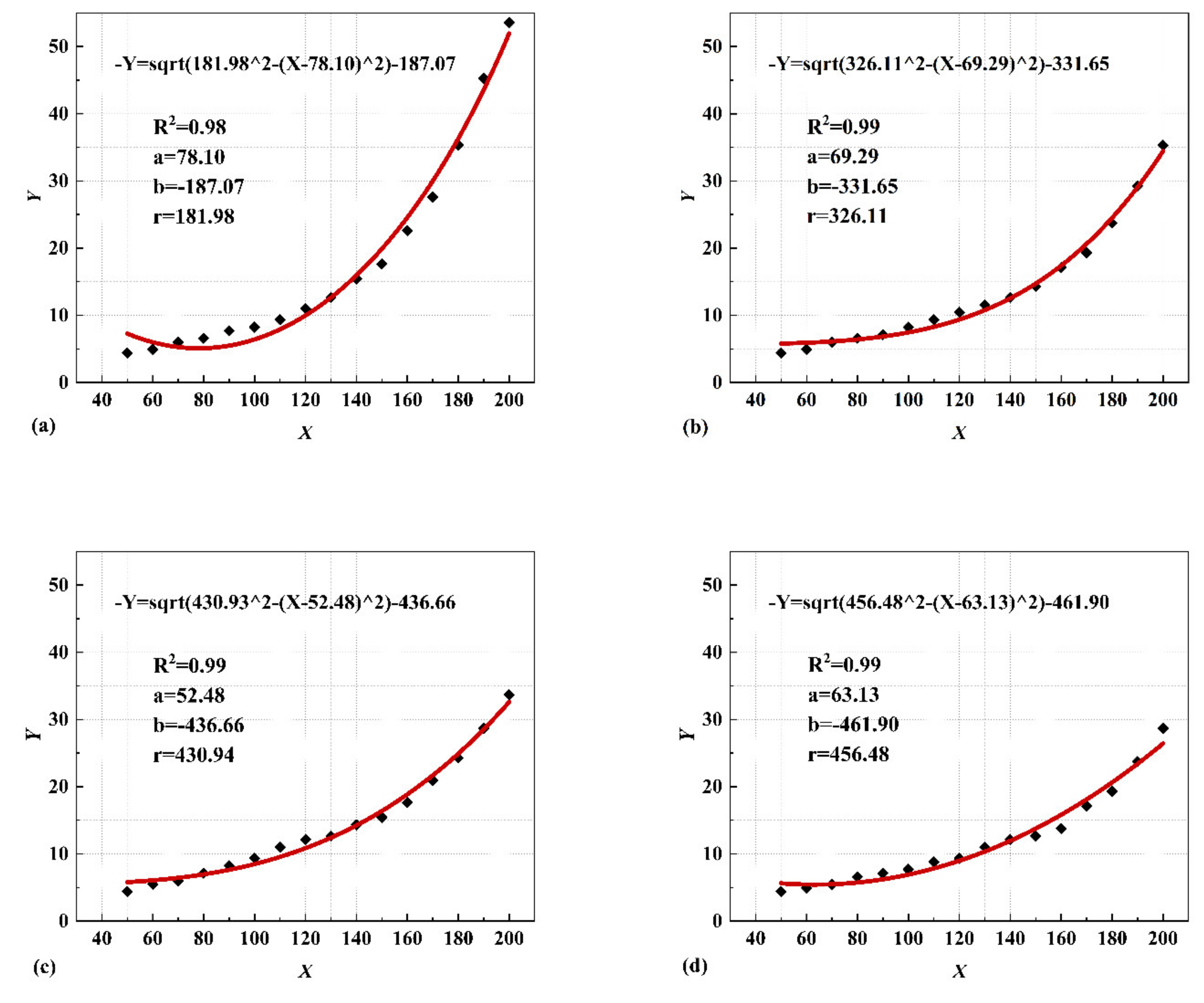
If the maximum velocity points in the convergence zone of the dual jets are connected, the center streamline of the curved jet can be derived. The center streamline can be fitted with a circular arc. This is the radius of curvature of the center streamline of the jet before the union of the dual jets. R
2 is the square root of the sum of squares of the residuals between the output variable (Y) and the independent variable (X). The fitting function is as follows:
From
Figure 8, the radius of curvature of the jet center streamlines of the dual jets becomes larger as the velocity increases in a certain range. In general, the deflection of the jets is caused by the asymmetry of the jet mixing and the pressure difference between its two sides. However, in this case, it is sufficient to consider only the pressure difference, which has a greater effect on the deflection than the random mixing between hot and cold fluids. When these dual jets are combined, the synthesized single jet will resemble a classical single jet.


