Article

Design and Simulation of End Effector for Young-Pear-Bagging Robot

1
College of Mechanical and Electrical Engineering, Wenzhou University, Wenzhou 325035, China
2
Institute of Laser and Optoelectronics Intelligent Manufacturing, Wenzhou University, Wenzhou 325035, China
3
Institute of PingYang Intelligent Manufacturing, Wenzhou University, Wenzhou 325035, China
*
Author to whom correspondence should be addressed.
Processes 2024, 12(2), 259; https://doi.org/10.3390/pr12020259
Submission received: 27 December 2023 / Revised: 18 January 2024 / Accepted: 20 January 2024 / Published: 25 January 2024

Abstract

:
In order to address the time-consuming and labor-intensive challenges as well as the suboptimal operational quality encountered in the conventional processes of fruit bagging within expansive orchards, an innovative end-of-bagging actuator is proposed, which can be installed on a fruit-production robot. Due to the excessive power sources required to complete the bagging operation, while also taking into account the quality and cost of the end effector, we have implemented a clutch transmission system to control individual motors, thereby achieving efficient bag-opening and collection actions. Through kinematic analysis of the bagging end effector, the optimal bag opening size is determined to be 40.3372 mm, with a deviation of 0.1428 mm from the design target and an error rate of 0.35%. This ensures the desired bag size for bagging juvenile fruits. Moreover, a dynamic simulation model comprising rigid drive components and a flexible clutch was developed. The simulation results demonstrate the system’s stable performance. However, it is evident that the gear speed falls below that of the flexible clutch, resulting in insufficient bag opening and bag gathering compared to the intended design target. The observed phenomenon is a result of the characteristics exhibited by the flexible clutch. Specifically, the demands for bagging and stretching can be accommodated by modifying the stiffness and geometric configuration of the flexible clutch, alongside the level of operational force. To conclude, the suggested end effector can successfully simulate the implementation of the manual bagging process. By taking into account the quality and cost of the end effector, a clutch drive system was utilized to regulate a single motor, resulting in efficient bag-opening and collection actions. This approach offers a more integrated and efficient solution compared to manual bagging and semi-automatic mechanically assisted bagging methods.

1. Introduction

With the advancement of living standards, the demand for eco-friendly well-being has surged, leading to heightened expectations regarding fruit quality. In their natural habitat, fruits lack sufficient safeguarding, rendering them vulnerable to pesticide residues, pests, diseases, and even natural disasters. This results in substandard appearance, compromised quality, and diminished benefits, and, in some cases, renders the fruits inedible [1]. Such circumstances have a profound impact on both fruit yield and economic gains. To address these challenges, fruit-bagging technology emerged as a viable solution, effectively enhancing fruit quality. As a pivotal technique in fruit-tree cultivation operations, fruit-bagging technology has achieved widespread adoption both domestically and internationally [2,3]. This innovative approach ensures the unhindered growth and ripening of fruits, reduces pesticide residues, effectively mitigates the impact of pests, diseases, extreme weather, and other factors affecting fruit quality [4,5,6,7], substantially curtails bird damage and mechanical harm during the fruit’s growth process [8], improves fruit aesthetics [9], and adds supplementary values such as safety, hygiene, and health, consequently yielding greater economic benefits to the fruit industry [10,11,12].
Nevertheless, conventional bagging techniques encounter numerous challenges and limitations. Primarily, bagging entails elevated labor and material expenses. The manual execution of bagging operations by farmers and the necessity of a bag for each individual fruit impose substantial demands on human resources and economic inputs. Furthermore, the utilization of disposable paper fruit bags contributes to increased pollution when improperly discarded. Secondly, bagging can influence the respiration and photosynthesis processes of the fruit, subsequently impacting its color [13]. The dim lighting conditions and localized greenhouse effect generated by bagging alter the fruit’s growth cycle, ultimately influencing its overall quality. Additionally, the large-scale implementation and efficient management of bagging technology present operational difficulties due to the requisite professional knowledge and skills demanded of farmers. Naturally, these challenges can be mitigated by exploring alternative solutions and optimizing the advantages of bagging technology. Particular emphasis should be placed on the proper recycling and reuse of discarded paper bags [14]. Researchers have continually proposed innovative bagging devices and automated robots to address the issues associated with bagging technology. However, the majority of mainstream fruit-production robots currently available are bulky and intricate machines that incorporate bagging as merely one of their functions, alongside mechanical pruning, leaf spraying, and fruit picking. While these robots offer high efficiency and diverse functionalities, their size and cost render them more suitable for large-scale orchards and farms specializing in fruit tree cultivation, and their research advancements have yet to be widely implemented. For example, the School of Agriculture at Okayama University in Japan developed a multifunctional and versatile intelligent robot based on trellis cultivation technology [15]. This robot is capable of fruit thinning, shaping, medication spraying, bagging, and pruning residual branches and leaves by interchanging its end effector. Vrochidou et al. [16] designed an autonomous grape harvesting robot that relies on an integrated system architecture and employs multifactorial positioning (aerial, remote control, and ground units) for multipurpose operations such as fruit thinning, leaf thinning, and harvesting. In the context of small orchard planting areas, limited fruit production, and challenging terrains, a cost-effective auxiliary fruit-bagging device proves more practical than an automated fruit-bagging robot. Hua et al. [17] proposed a novel semi-automatic fruit-bagging device that utilizes the self-locking principle of nuts and bolts. The device accomplishes fruit bagging by securing paper bags with rubber bands and plastic rings without requiring additional power sources.
Even though in a different application, the speed of motion and positioning accuracy of a robot are crucial factors [18]. It is worth noting that lightweight robots, including fruit robots, may have lower stiffness and insufficient accuracy compared to ordinary industrial robots [19]. To address these challenges, Xia et al. [20] designed a conventional paper fruit bag supply device for fruit bagging and established a multi-body dynamics model to simulate the interaction between the opening mechanism and the paper fruit bag. Based on the simulation results, at a slider speed of 200 mm/s, it can be observed that as the slider stroke increases, the maximum equivalent force applied to the paper fruit bag also increases until the bag breaks. Furthermore, when the velocity exceeds 300 mm/s, the device experiences vibrations. Additionally, Zhang Kai et al. [21] designed an ontology structure for the robot system based on cylindrical coordinates, specifically targeting trellis grape planting in horticulture. They proposed an algorithm based on a genetic algorithm for target feature extraction. Their tests demonstrated the following results: when the navigation vehicle was moving at a speed of 0.3 m/s, the grape target recognition rate reached 95%, and the average time required for grape target recognition was 136 ms. Additionally, the success rate of robotic bagging reached 85%, with an average time of 39.6 s consumed for bagging single bunches of grapes. These findings highlight the effectiveness of the proposed approach in achieving high recognition rates and successful bagging in a timely manner.
The aforementioned study holds significant importance in the realm of designing bagging apparatus for juvenile fruits. This paper aims to elucidate various aspects pertaining to bagging. Primarily, it presents a comprehensive overview of the structural framework and operational procedures associated with the bagging end effector. Subsequently, it delves into a detailed explanation of the design principles governing the key components. Lastly, the structural viability is assessed through meticulous kinematic analysis, while the system’s transfer control stability is substantiated via multi-body dynamics simulation. Positioned as an end modular component of the fruit robot, this device exhibits adaptability, allowing for seamless replacement to accommodate diverse fruit varieties. This capability not only curtails production costs but also enhances operational efficiency.

2. Materials and Methods

2.1. Bagging Agronomy
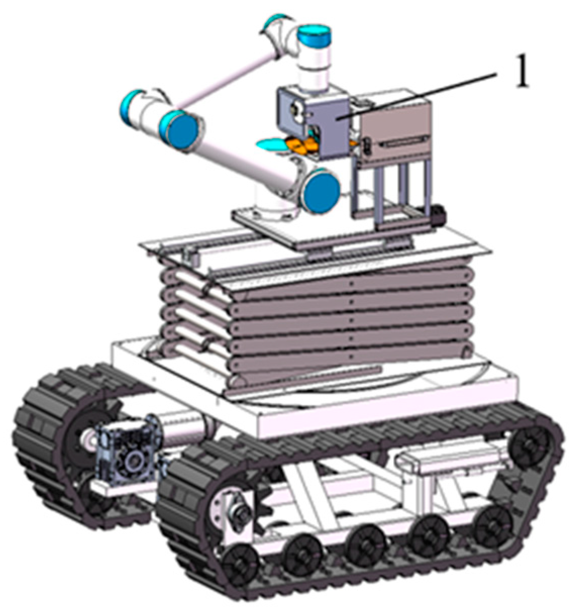
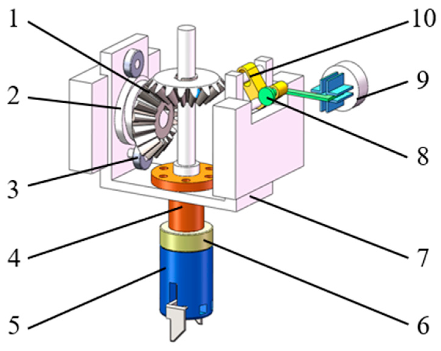
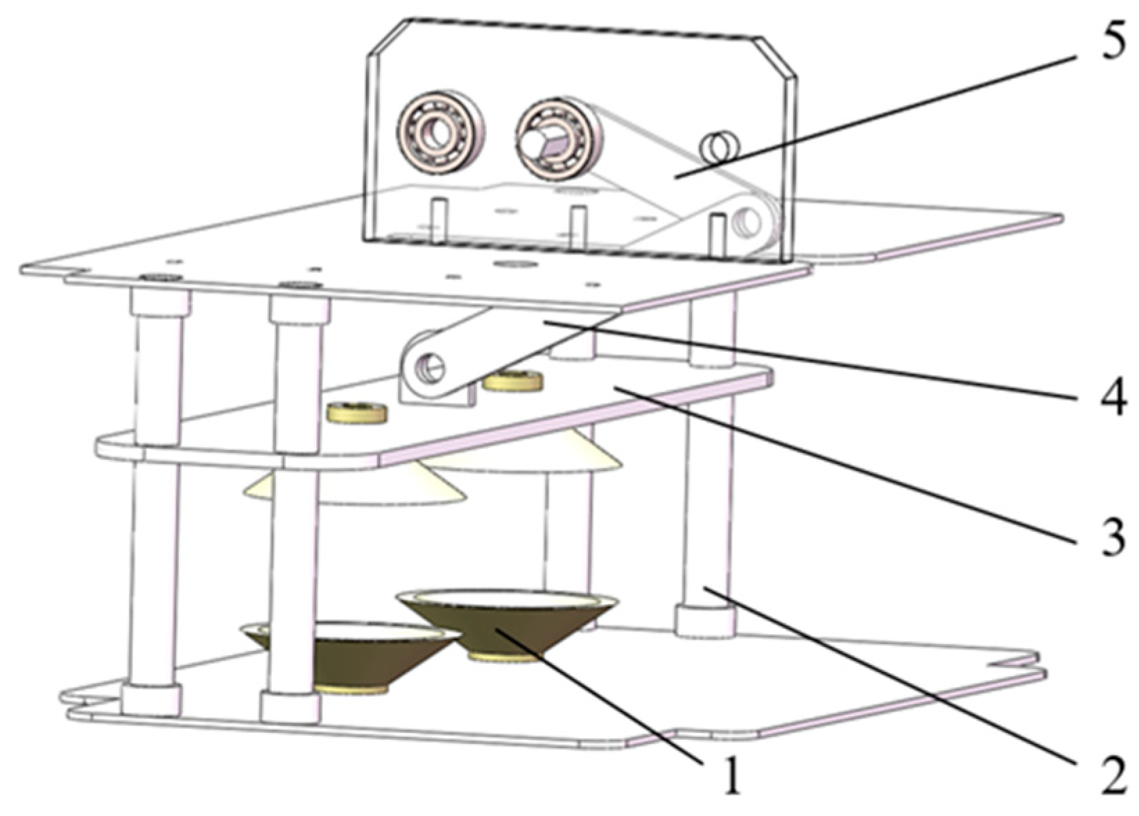
The growth process of pears can be categorized into four stages (Table 1), wherein the fruit enlargement phase is susceptible to external environmental factors. After 20 to 40 days following the blossoming of the pear trees, the pear fruit enters the expansion phase. To prevent the occurrence of whorl disease, early bagging is recommended for green pear varieties, while brown pear varieties can be bagged at a later stage. As an illustration, Autumn Moon pears typically have a fruit diameter of 12–17 mm at 20 days, 20–25 mm at 30 days, and 28–33 mm at 40 days. Although the fruit sizes of different pear varieties may vary slightly, they generally fall within this range. Bagging should occur when the transverse diameter of the fruit is less than 30 mm and the spots have not yet appeared. Consequently, the main parameters for the juvenile-fruit-bagging robot’s work object can be determined as follows (Table 2).

2.2. Structure

The bagging end effector is affixed to the fruit-production robot, serving as its mounting platform, as illustrated in Figure 1. Constituting an integral facet of the modularized design, it is amenable to selection and configuration based on specific requirements. This adaptability allows for tailoring the system to the distinct needs of various crops and orchards, fostering a more flexible and efficient operational paradigm. Consequently, this design affords increased convenience and benefits to agricultural production.
The bagging end effector primarily comprises a framework, a bag-gathering component, a bag-sealing component, a wire-feeding component, a transmission component, and a bag-expanding component, as depicted in Figure 2. It is capable of executing functions such as bag expanding, gathering, and sealing in a single operation. The wire-tying and cutting component is primarily composed of a bevel gear assembly, double cams, rollers, a coupling, a wire-tying finger, elastic rings, a U-shaped plate, a cutting knife, a wire-guiding groove, and a linkage, enabling the simultaneous completion of wire tying and cutting actions, as shown in Figure 3. The core components include the transmission component, bag-expanding component, and bag-sealing component, as shown in Section 2.4.

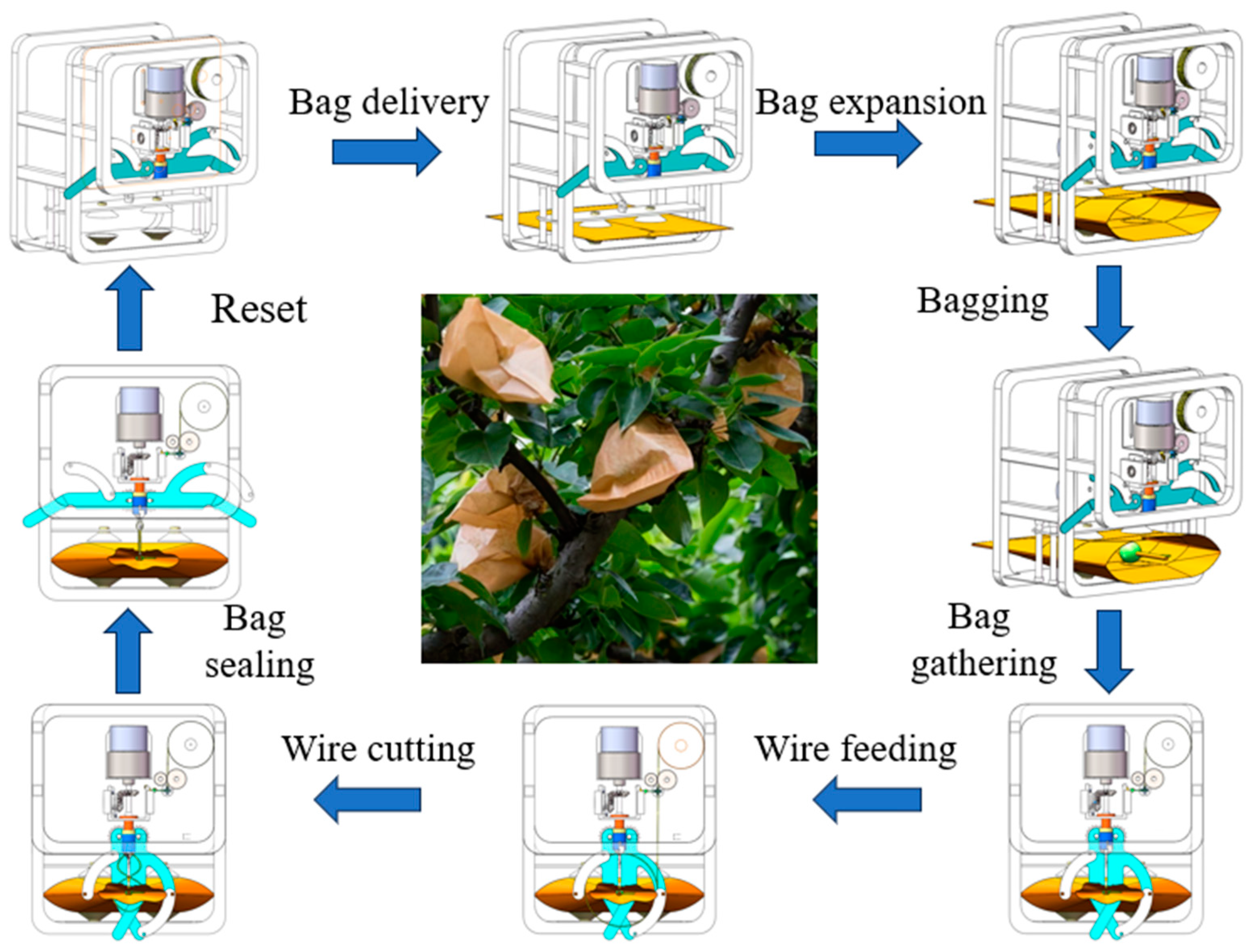
2.3. Operational Mechanism

The bagging process can be outlined in four distinct phases: bag expansion, bag placement, bag gathering, and bag sealing. The sealing process involves wire feeding, wire tying, and wire cutting, as illustrated in Figure 4. The paper bag is horizontally transported to the bag-expanding component, where the opening action is accomplished through the utilization of vacuum suction cups and an offset crank-slider mechanism. Four symmetrically positioned suction cups secure the paper bag, and the rotary motion of the motor is converted into the reciprocating motion of the bag-expanding plate through the crank-slider device, effectuating the bag-expanding action.
Upon energizing the circular electromagnet (located away from the motor), the resulting magnetic field attracts the iron pieces. Influenced by the clutch and the detent fork, the iron pieces shift rightward, engaging with the driving gear. The DC reduction motor is activated, and through intermediate gear transmission it propels the bag-expanding plate in a vertically downward motion, causing the vacuum suction cups to adhere to both sides of the fruit bag. Subsequently, the motor reverses, moving the bag-expanding plate in the opposite direction, smoothly expanding the fruit bag. The juvenile fruit is seamlessly placed into the bag.
Upon de-energizing the circular electromagnet (located away from the motor) and energizing the circular electromagnet (proximate to the motor), the clutch, under the influence of the detent fork, shifts leftward and engages with the driving gear. The DC reduction motor is activated, and the clutch, biased leftward, engages with the driving gear. Through intermediate gear and bevel gear transmission, it propels the bag-gathering rod to complete the gathering of the fruit bag. The wire-feeding motor is activated, guiding the iron wire through the wire-guiding groove in the bag-gathering component, forming a circular trajectory around the fruit stem. The wire-tying finger further tightens the wire loop, completing the sealing of the fruit bag, simultaneously driving the cutting knife to complete the wire cutting. Finally, the bag-gathering rod returns to its initial position, the bagging machine retracts, and the entire bagging operation is accomplished in one cycle.

2.4. Analysis of Critical Component

The core components include the transmission component, the bag-expanding component, and the bag-sealing component. The transmission component, as illustrated in Figure 5, consists primarily of a gear assembly, a flexible clutch, circular electromagnets, iron pieces, and a detent fork. Through clutch-controlled gear transmission, it independently realizes the actions of bag expanding and gathering. The bag-expanding component comprises a bag-expanding plate, a stroke column, a bag-expanding connecting arm, a vacuum suction cup, and a bag-expanding rotary arm. It utilizes a vacuum suction cup and an offset crank-slider mechanism to achieve the opening action of the paper bag, as illustrated in Figure 6. The design schematic of the bias crank slider is shown in Figure 7. The bag-gathering component, as shown in Figure 8, consists of a ring plate, a wire-guide groove, and a wire stopper.

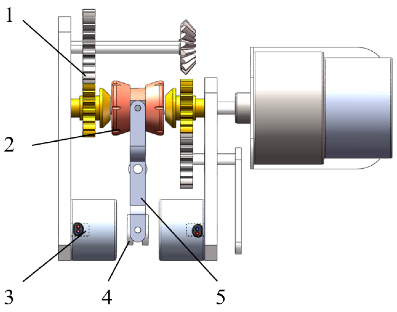
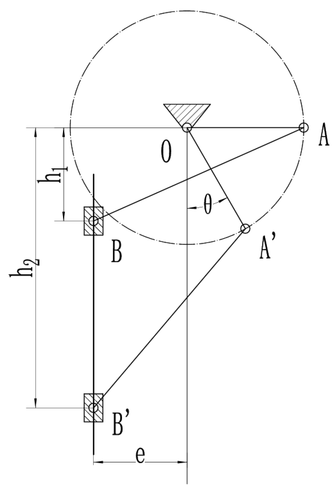
2.4.1. Transmission Component

Due to the excessive number of motors required for completing the bagging operation and considering the factors of end effector weight and cost, this paper implements control over the circular electromagnet, enabling the engagement of the clutch and gear mechanisms accordingly, thereby achieving efficient bag-opening and collection actions.

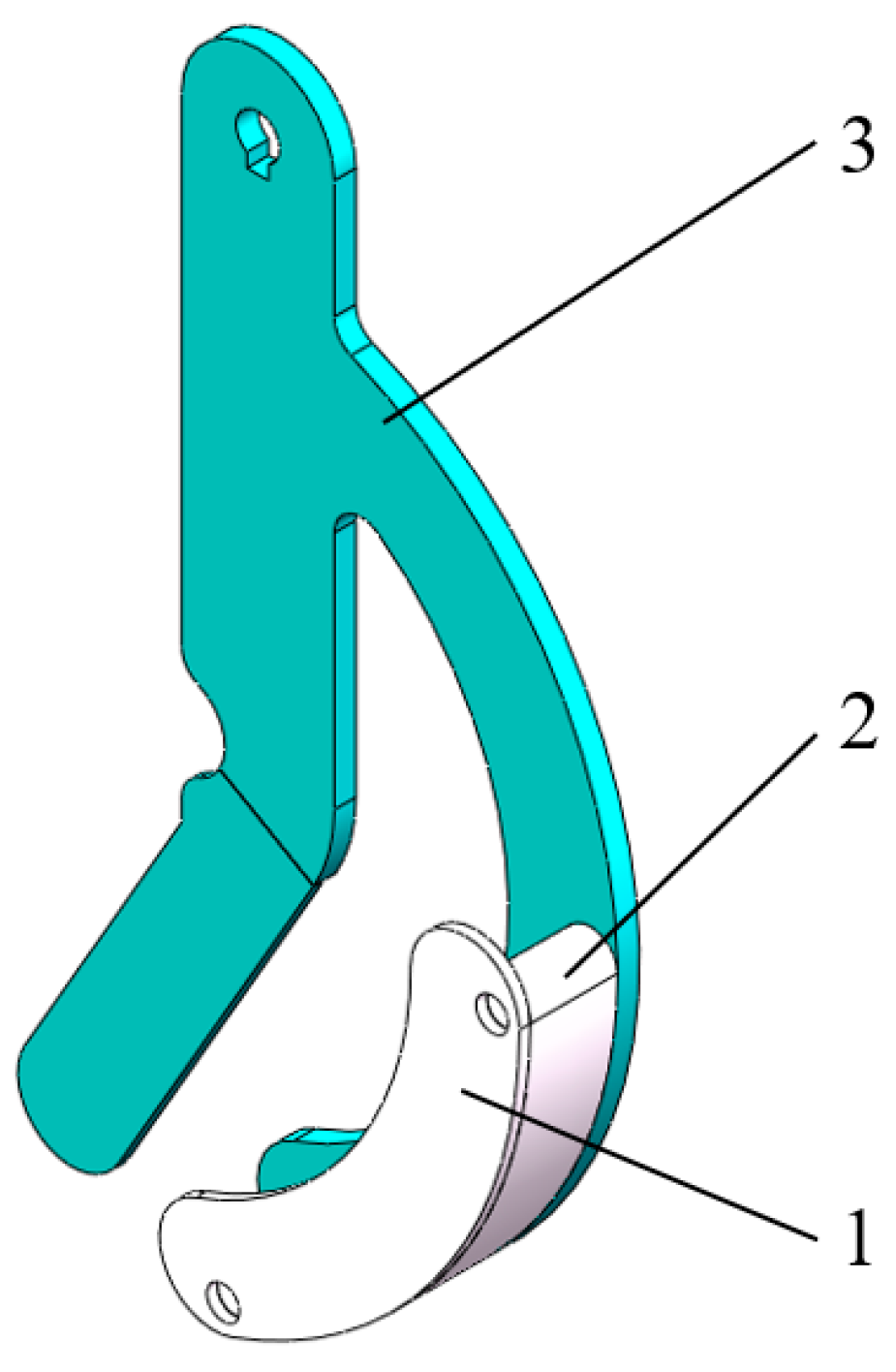
2.4.2. Bag-Expanding Component

According to the principle of bagging analysis, the bag-opening action is crucial in the overall bagging process and plays a key role in the successful implementation of bagging. By carefully considering the size of the bag opening in relation to the target fruit size, the bagging process can be optimized to provide the best conditions for the growth and protection of the juvenile fruit. The size of the paper bag opening should be suitable for the shape and size of the fruit being bagged. In this paper, where the paper bag size is 150 mm × 180 mm and the target size for bagging juvenile fruit is 20 mm to 30 mm, it is important to design the open bag range to be larger than the bagging target size. In this case, a range of 40 mm has been chosen to ensure that it adequately accommodates the desired size of the juvenile fruit being bagged. This design choice ensures that the bag opening is large enough to effectively enclose the juvenile fruit within the bag during the bagging process.
During the bag-opening process, optimum bag opening is achieved when the vacuum suction cup applies force near the mouth of the paper bag. To achieve this, the design incorporates the offset crank-slider mechanism, as illustrated in the Figure 7 below. The crank angle ranges from 0° to −60°, and the slider’s distance from the O point must be between 20 mm and 60 mm. The crank has a length of O A while the connecting rod’s length is A B , both of which are located at the starting position of the crank and the slider.
From the trigonometric functions and the Pythagorean theorem, the following equations can be derived:
O A + e 2 + h 1 = A B 2
h 2 O A sin θ 2 + O A cos θ + e 2 = A B 2
And as for 60 ° θ 0 ° , can be obtained:
b 2 a + e 2 = h 1
b 2 a cos θ + e 2 a sin θ = h 2
where a—crank length; b—connecting rod length; e—offset; θ—polar angle; h1—distance relative to the origin at the initial position of the slider; and h2—the distance relative to the origin at the limit position of the slider.
After substituting h1 = 20 mm, h2 = 60 mm, and e = 20 mm into the formula and using MATLAB R2022b, the values for a and b are calculated as 25.822 mm and 49.997 mm, respectively. Rounding these results, we obtain a = 26 mm and b = 50 mm. The condition a + e < b is satisfied, confirming that O A functions as the crank in the design. Hence, the length of the designed crank (rotating rod) is 26 mm, and the length of the connecting rod (driven rod) is 50 mm.
When the crank angle is 0°, the distance of the slider with respect to the origin reaches its minimum value. By substituting the lengths of the crank and connecting rod, we can determine this minimum distance.
h 1 = M i n x B = 50 2 26 + 20 2 = 19.60   m m
When the crank angle is −60°, the distance of the slider with respect to the origin reaches its Maximum value. By substituting the lengths of the crank and connecting rod, we can determine this minimum distance.
h 2 = M a x x B = 50 2 26 × 1 2 2 + 26 × 3 2 = 60.08   m m
h = h 2 h 1 = 60.08 19.60 = 40.48   m m
The conclusion drawn from the given information is that when the crank length is 26 mm and the connecting rod length is 50 mm, and the crank angle ranges from 0° to −60°, the size of the bag opening measures 40.48 mm. This measurement surpasses the desired size range of 20–30 mm for bagging small fruits. It ensures that the paper bag expands adequately to accommodate fruits of diverse shapes and sizes.

2.4.3. Bag-Gathering Component

To imitate the manual method of effectively sealing a fruit bag, the open end of the bag must be placed in the center of the closing mechanism. This ensures that the mechanism effectively closes in proximity to the fruit stalks, leaving an appropriate amount of space. It is crucial that the closure is neither excessively large nor too small. An oversized closure may lead to challenges during subsequent sealing steps due to the presence of fruit stalks, while an undersized closure can result in damage to the fruit stalks, thereby impacting the growth of juvenile fruits. The wire ties are arranged in circular loops along pre-determined wire-guide grooves encircling both the fruit bag and the fruit stalks within it. This arrangement allows for the loops to be subsequently tightened, ensuring a secure seal.

3. Results and Discussion

3.1. Kinematic Analysis

Due to the intricate process of energizing a circular electromagnet to produce a magnetic field and attract the iron sheet, a simplified model was developed.
In this simplified rendition, direct impulsion is utilized to drive the iron sheet, ensuring the requisite engagement for transmission. To achieve this, several adjustments were implemented. Initially, solid-to-solid contact was established between the upper slider and the clutch. Similarly, contact was established between the lower slider and the clutch, the clutch and the flexible sheet, and the iron sheet and the ground, serving as a reference system. Moreover, a mobile vice was integrated along the Z-axis direction for the iron plates to symbolize motion towards the circular electromagnet. A drive mechanism was incorporated, employing the functional expression “step (time, 0, 0, 1, 3)”. This function facilitates the movement of the iron sheet by 3 mm towards the circular electromagnet within the time frame of 0 to 1 s, effectively simulating the generation of a magnetic field upon energizing the electromagnet and consequent attraction of the iron piece. The model also encompasses a rotating vice, interconnecting various components such as the gear set, the rotating arm, the connecting arm, and the tensioning bag plate. Kinematic simulation is conducted to analyze the displacement, velocity, and acceleration graphs of the clutch and the bag tensioning plate.
Based on the information provided (Figure 9), it can be observed that the clutch displacement graph shows the position of the iron plate at different time intervals. Initially, at 0 s, the iron plate is located at −3.2616 mm on the x-axis. After 1 s, it moves to the right limit position, which is at −6.2616 mm on the x-axis. Finally, at 4 s, the clutch moves to the left limit position, which is at −0.2616 mm on the x-axis. The movement range of the clutch is stated to be 6 mm, which means that the distance between the right limit position and the left limit position is 6 mm. This displacement range satisfies the required displacement needs of the clutch and is in accordance with the design requirements.
It demonstrates that the speed variation during the clutch movement exhibits a more consistent and uninterrupted pattern (Figure 10). There are no abrupt fluctuations or sudden shifts observed. However, some fluctuations can be observed in the initial stage of clutch acceleration, followed by a linear progression. This behavior can be attributed to the inherent kinetic characteristics of the clutch and the transmission system, which influence the acceleration.
Based on the displacement curve of the bag-opening plate (Figure 11), several key observations can be made. Firstly, at t = 0 s, the bag-opening plate is in its initial position, with a y-axis position of −42.819 mm. At t = 1 s, the bag-spreading plate reaches its limit position, with a y-axis position of −83.1562 mm. Finally, at t = 2 s, the bag-spreading plate returns to its initial position, with a y-axis position of −42.819 mm. The movement range of the bag-spreading plate can be calculated by subtracting the initial position from the limit position. Thus, the movement range is 40.3372 mm. This range is greater than the cross diameter of the juvenile fruit bag. Furthermore, comparing the calculated bag range (40.48 mm) in the third chapter with the actual movement range, there is a difference of 0.1428 mm. This difference represents an error of 0.35%, which is within the acceptable error tolerance. Therefore, the bag-opening plate meets the design requirements.
Figure 12 reveals that both the velocity curve and acceleration curve exhibit a continuous and gradual change in their characteristics. There are no sudden or drastic fluctuations or discontinuous jumps observed. This indicates that the movement of the tensioning plate maintains a relatively smooth speed, and the tensioning plate experiences relatively uniform impetus or resistance. Consequently, the state of the tensioning plate during its movement remains relatively stable, ensuring stability for the bagging.

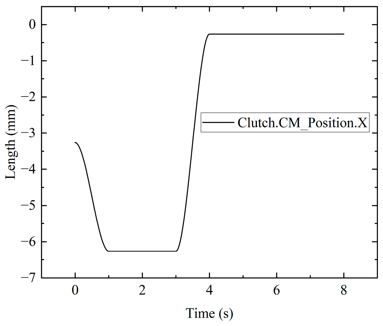
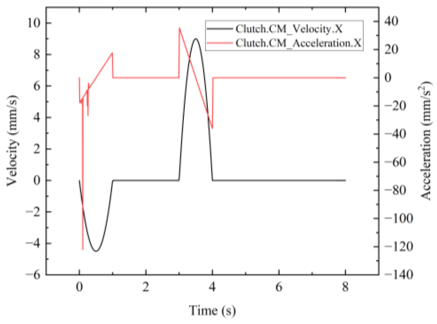
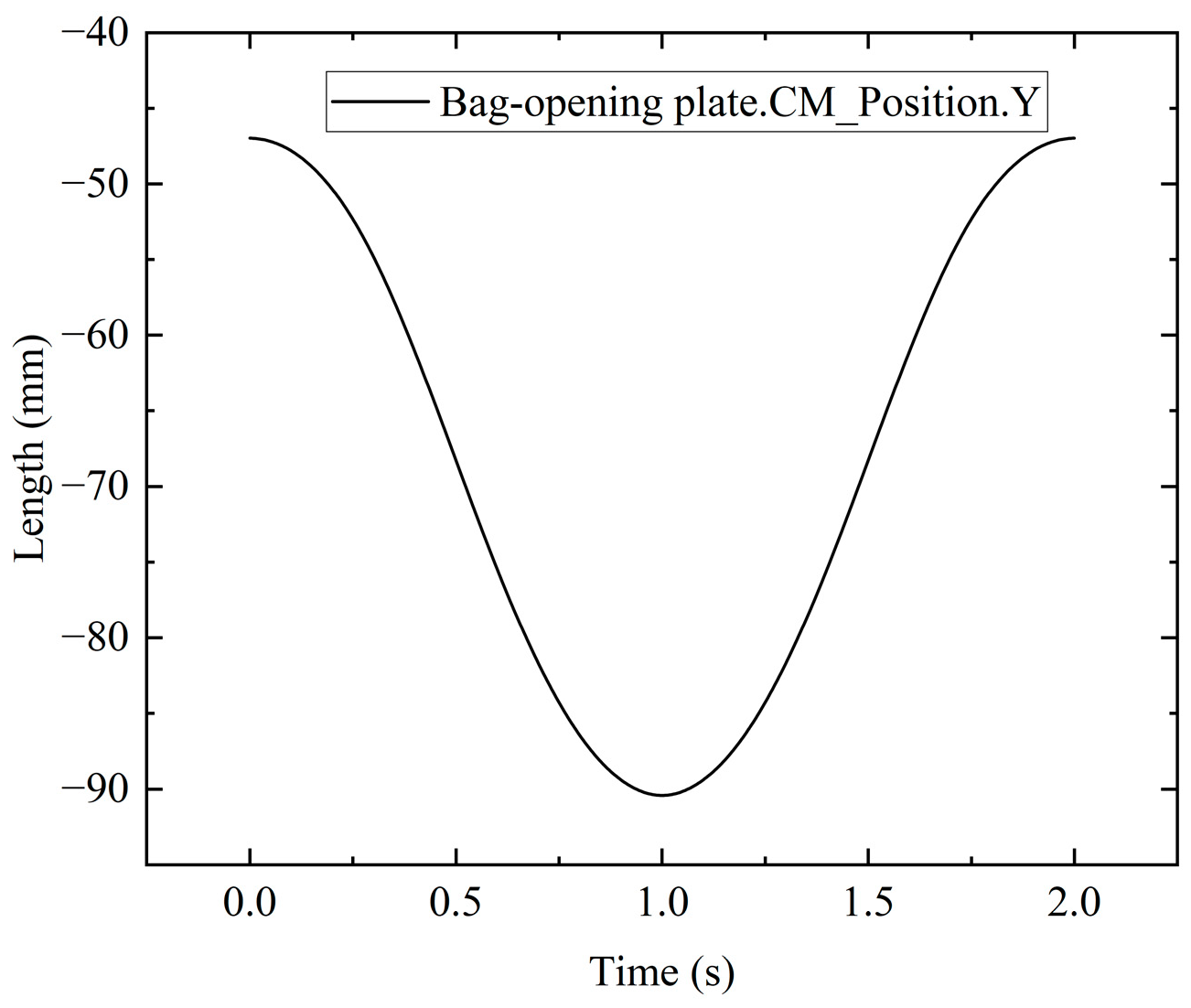
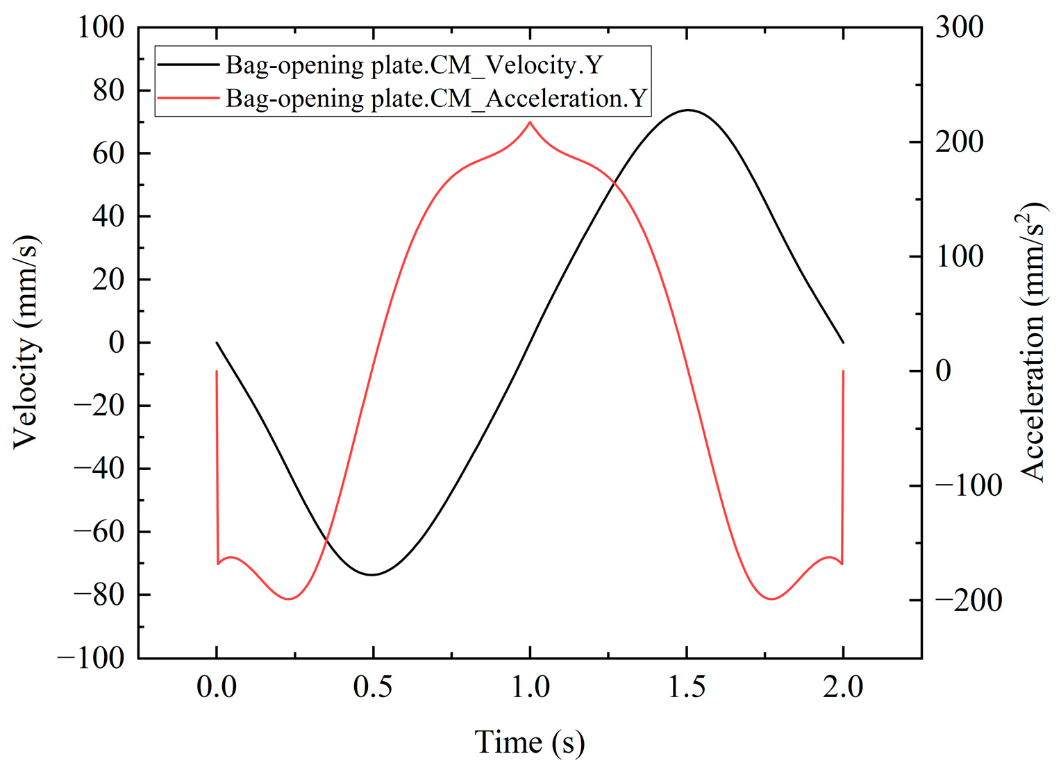
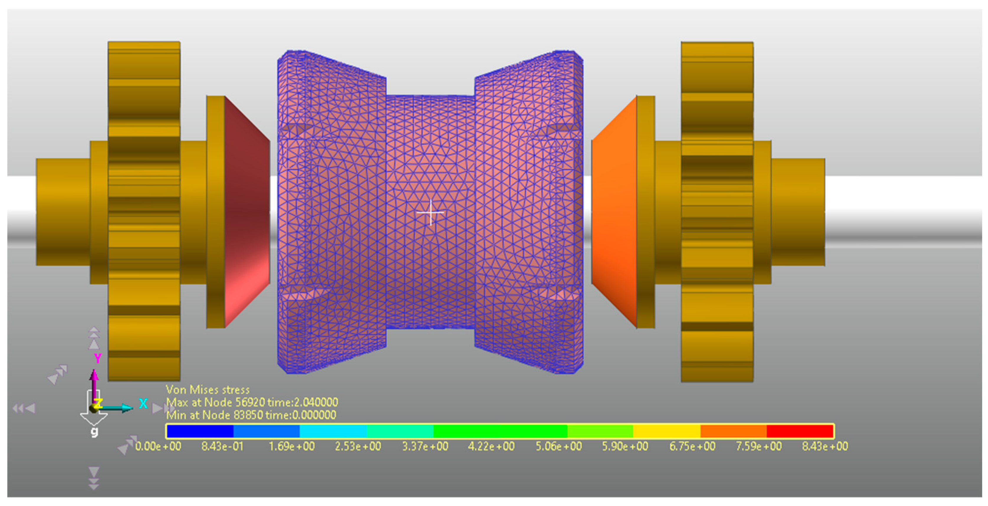
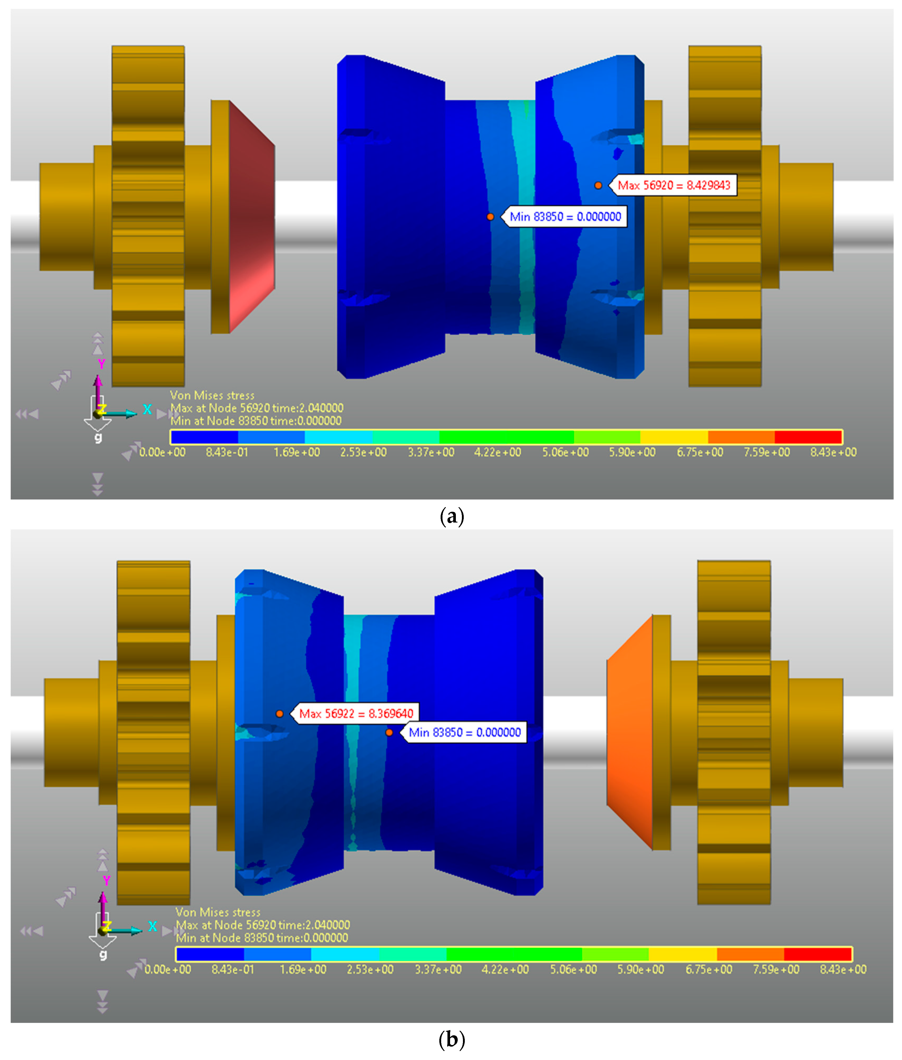
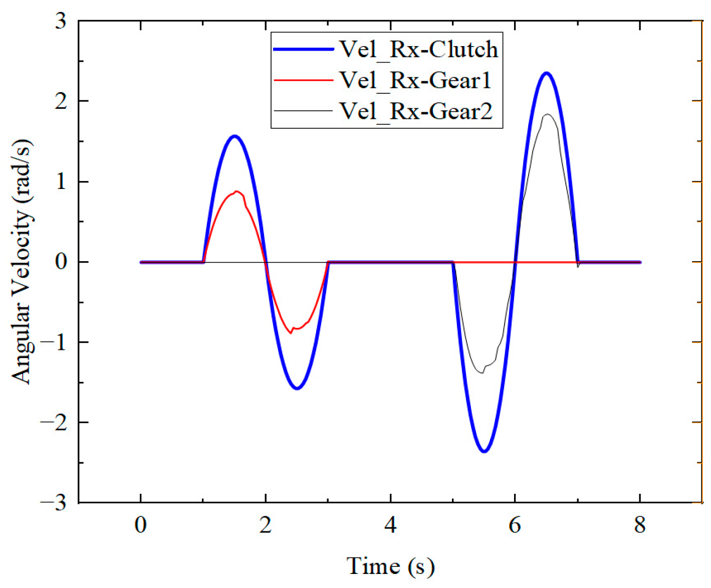
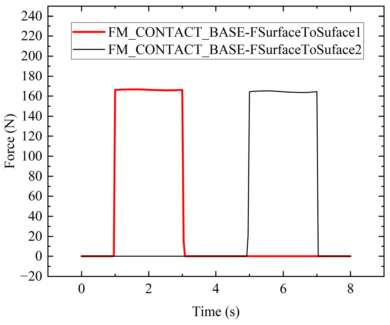
3.2. Dynamic Analysis

The modeling and assembly of the clutch, gears, and drive shaft were completed, and the model was imported into RecurDyn V9R5 to establish a dynamic model. In the RecurDynV9R5, the Library module was utilized to set the material of the drive shaft and gears as steel. In the Flexible module, the clutch was meshed using solid elements (Solid4/Tetra4), and considering computational precision and time, the minimum mesh edge length was defined as 0.3 mm. The mesh was created with 19,272 nodes and 97,831 elements (Figure 13). Material properties for the meshed flexible plate were added based on the considerations outlined in Table 3.
To facilitate the addition of contact, the clutch is modeled as a set of patches through Patch. Simultaneously, the contact type between the flexible clutch and gear is set to FSurface to Surface Contact, with the relevant contact parameters detailed in Table 3. The flexible clutch is incorporated as a moving component along the x-axis with the drive shaft as the reference system. A Displacement (time) drive function is added, expressed as step(time, 0, 0, 1, 3) + step(time, 3, 0, 5, 6) + step(time, 7, 0, 8, −3). Specifically, during the interval of 0–1 s, the flexible clutch moves 3 mm in the positive x-axis direction to engage with gear 1; from 3–5 s, the flexible clutch moves 6 mm in the negative x-axis direction to engage with gear 2; and from 7–8 s, the flexible clutch returns to its original position. The shaft is introduced as a rotating component with the ground as the reference system, rotating along the x-axis direction. A Displacement (time) drive function is added, and the function expression is step(time, 1, 0, 2, −pi/3) + step(time, 2, 0, 3, pi/3) + step(time, 5, 0, 6, pi/2) + step(time, 6, 0, 7, −pi/2). This signifies that from 0–1 s, the axis rotates clockwise by 60°; from 2–3 s, the axis rotates counterclockwise by 60°; from 5–6 s, the axis rotates counterclockwise by 90°; and from 6–7 s, the axis rotates clockwise by 90°.
Conducting multi-body dynamics simulation, the force distribution map of the flexible clutch is shown in Figure 14. From the graph, it is evident that the stress on the flexible clutch is concentrated in the region where it contacts the gears, and the distribution is relatively uniform.
As shown in Figure 15, at 1 s, the flexible clutch contacts Gear 1. From 1 to 3 s, the flexible clutch first rotates counterclockwise by 60° and then clockwise by 60°, reaching a peak speed of 1.58 rad/s and a trough speed of −1.58 rad/s. The speed curve is smooth. During this time, Gear 1 has a peak speed of 0.89 rad/s and a trough speed of −0.83 rad/s. The analysis (Table 4) reveals that Gear 1 first rotates counterclockwise by 33.8° and then clockwise by 31.5°, with fluctuations in the speed curve. At 5 s, the flexible clutch contacts Gear 2. From 5 to 7 s, the flexible clutch first rotates clockwise by 90° and then clockwise by 90°, reaching a peak speed of 2.36 rad/s and a trough speed of −2.36 rad/s. The speed curve is smooth. At this time, Gear 2 has a peak speed of 1.84 rad/s and a trough speed of −1.38 rad/s. The analysis (Table 4) shows that Gear 2 first rotates clockwise by 70.1° and then clockwise by 52.6°, with fluctuations in the speed curve. The study indicates that the gear speed is lower than the clutch speed, and the speed extremum of the gear has a certain delay relative to the flexible clutch. Additionally, the rotation angle of the gear is less than the design target. As shown in Figure 16, the contact force between the flexible clutch and the gears is 165 N, exhibiting fluctuations.

3.3. Discussion of Flexible Clutch

Aligned with bagging agronomy, the paper achieves bag-opening and -gathering actions through a motor using clutch transmission, as determined by action timing analysis and design optimization.
This paper employs an offset crank-slider mechanism to execute the bag-opening action, ensuring that the vacuum suction cup approaches the mouth of the paper bag for an improved opening effect. The size of the juvenile fruit bag ranges from 20 to 30 mm. In the kinematic analysis, the determined bag-opening range at the end effector is 40.3372 mm, with a design target size of 40.48 mm. The discrepancy between the two is 0.1428 mm, classified as a relative error with a value of 0.35%, which meets the target size for bagging juvenile fruits.
Dynamic simulation analysis reveals that the speed of the gear is lower than that of the clutch and the rotation angle of the gear is smaller than the design target. This phenomenon is attributed to the characteristics of the flexible clutch. Specifically, when the flexible clutch transmits torque, a portion of the torque is absorbed and stored due to the presence of an elastic element. The magnitude of this stored torque depends on the stiffness and geometry of the elastic element, as well as the magnitude of the operating force. In particular, the requirements for bag opening and bag closure can be met by adjusting the stiffness and geometric configuration of the flexible clutch, as well as the operational force level.

4. Conclusions

To solve problems with conventional fruit harvesting, the article proposes an innovative bagging end actuator that can be installed on a fruit-producing robot. Based on the presented structures and analyses, conclusions were formulated:
  • We proposed a modularized design of a bagging end effector for fruit-production robots which allows for selection and configuration based on specific needs, enabling adaptability to different crops and orchards. Consequently, it achieves more flexible and efficient operation, providing enhanced convenience and benefits to agricultural production.
  • Through action timing analysis and design optimization, the paper implements a motor for completing the bag-opening and bag-gathering actions via clutch transmission. This approach simplifies the system structure, reducing manufacturing costs while effectively controlling action timing to enhance accuracy and stability.
  • The utilization of multi-body dynamics simulation software in this paper facilitates the simulation and analysis of flexible clutch transmission. This intuitive tool allows for the observation of various motion laws for each component and the derivation of characteristic curves. The results indicate that multi-body dynamics simulation software offers a rapid and reliable method for conducting structural design research.
The proposed analytical approach can be utilized to simulate the interaction between the bag-gathering component and the paper bag itself. As a result, research will be conducted in the future to optimize the bag-gathering process and achieve superior results. Additionally, future work will comprise the development of identification and positioning systems specifically tailored for young pears during bagging operations, as well as control systems aimed at automating the bagging.

Author Contributions

Conceptualization, Y.S. and C.T.; methodology, M.W. and Z.C.; data curation, C.T. and Y.S.; writing—original draft, C.T.; writing review and editing, Z.C. and M.W. All authors have read and agreed to the published version of the manuscript.

Funding

This research was supported by the Key R&D Project of Zhejiang Province No. 2019C02019 and Wenzhou Municipal Key Science and Research Program No. ZN2022001.

Data Availability Statement

Data are contained within the article.

Conflicts of Interest

The authors declare no conflicts of interest.

References

  1. Kasso, M.; Bekele, A. Post-harvest loss and quality deterioration of horticultural crops in Dire Dawa Region, Ethiopia. J. Saudi Soc. Agric. Sci. 2018, 17, 88–96. [Google Scholar] [CrossRef]
  2. Ali, M.M.; Anwar, R.; Yousef, A.F.; Li, B.; Luvisi, A.; De Bellis, L.; Aprile, A.; Chen, F. Influence of Bagging on the Development and Quality of Fruits. Plants 2021, 10, 358. [Google Scholar] [CrossRef] [PubMed]
  3. Sharma, R.R.; Reddy, S.V.R.; Jhalegar, M.J. Pre-harvest fruit bagging: A useful approach for plant protection and improved post-harvest fruit quality—A review. J. Hortic. Sci. Biotechnol. 2015, 89, 101–113. [Google Scholar] [CrossRef]
  4. Ahmed, T.; Hasan, M.; Hassan, K.; Ahmed, J.D.; Ahmed, K.S.D.; Azam, A.; Mondal, F. Fruit bagging of custard apple (Annona reticulata) as an eco-friendly protection approach against mealybug (Phenacoccus solenopsis) infestation in the north-eastern Bangladesh. Int. J. Trop. Insect Sci. 2021, 42, 723–732. [Google Scholar] [CrossRef]
  5. Frank, D. Evaluation of Fruit Bagging as a Pest Management Option for Direct Pests of Apple. Insects 2018, 9, 178. [Google Scholar] [CrossRef]
  6. Leisso, R.; Jarrett, B.; Mendrey, K.; Miller, Z. Bagging Apple Fruit for Codling Moth Control in Western Montana. HortTechnology 2021, 31, 500–503. [Google Scholar] [CrossRef]
  7. Matsumoto, K.; Kobayashi, T.; Kougo, T.; Fujita, T.; Sato, S.; Moriguchi, T. Prevention of New Cork Spot-like Physiological Disorder in ‘Kurenainoyume’ Apples by Pre-harvest Fruit Bagging. Hortic. J. 2018, 87, 174–183. [Google Scholar] [CrossRef]
  8. Amarante, C.; Banks, N.H.; Max, S. Preharvest bagging improves packout and fruit quality of pears (Pyrus communis). N. Z. J. Crop. Hortic. Sci. 2002, 30, 93–98. [Google Scholar] [CrossRef]
  9. Sharma, R.R.; Pal, R.K.; Sagar, V.R.; Parmanick, K.K.; Paul, V.; Gupta, V.K.; Kumar, K.; Rana, M.R. Impact of pre-harvest fruit-bagging with different coloured bags on peel colour and the incidence of insect pests, disease and storage disorders in ‘Royal Delicious’ apple. J. Hortic. Sci. Biotechnol. 2015, 89, 613–618. [Google Scholar] [CrossRef]
  10. Buthelezi, N.M.D.; Mafeo, T.P.; Mathaba, N. Preharvest Bagging as an Alternative Technique for Enhancing Fruit Quality: A Review. HortTechnology 2021, 31, 4–13. [Google Scholar] [CrossRef]
  11. Paul, J.R.; Prasad, K.; Lalrinngheta, J.; Mukhim, C.; Akshatha, H. Improving fruit quality by bagging technology. Food Sci. 2021, 2, 49–53. [Google Scholar]
  12. Zha, Q.; Xi, X.J.; He, Y.; Jiang, A.L. Bagging Affecting Sugar and Anthocyanin Metabolism in the Ripening Period of Grape Berries. Not. Bot. Horti Agrobot. Cluj-Napoca 2019, 47, 1194–1205. [Google Scholar] [CrossRef]
  13. Legua, P.; Martínez-Nicolás, J.J.; Guirao, P.; Hernández, F.; Núñez-Gómez, D.; Melgarejo, P. Influence of fruit bagging technique on the morphometric and biochemical characteristics of two pomegranate varieties (Punica granatum L.). Food Chem. Mol. Sci. 2022, 4, 100112. [Google Scholar] [CrossRef] [PubMed]
  14. Yang, H.; Gu, F.; Wu, F.; Wang, B.; Shi, L.; Hu, Z. Production, Use and Recycling of Fruit Cultivating Bags in China. Sustainability 2022, 14, 14144. [Google Scholar] [CrossRef]
  15. Kondo, N.; Monta, M.; Fujiura, T. Fruit harvesting robots in Japan. Adv. Space Res. 1996, 18, 181–184. [Google Scholar] [CrossRef] [PubMed]
  16. Vrochidou, E.; Tziridis, K.; Nikolaou, A.; Kalampokas, T.; Papakostas, G.A.; Pachidis, T.P.; Mamalis, S.; Koundouras, S.; Kaburlasos, V.G. An Autonomous Grape-Harvester Robot: Integrated System Architecture. Electronics 2021, 10, 1056. [Google Scholar] [CrossRef]
  17. Hua, Y.; Yang, B.; Zhou, X.-G.; Zhao, J.; Li, L. A novel progressively delivered fruit bagging apparatus. J. Appl. Hortic. 2016, 18, 123–127. [Google Scholar] [CrossRef]
  18. Peta, K.; Wlodarczyk, J.; Maniak, M. Analysis of trajectory and motion parameters of an industrial robot cooperating with a numerically controlled machine tools. J. Manuf. Process. 2023, 101, 1332–1342. [Google Scholar] [CrossRef]
  19. Metzner, M.; Leurer, S.; Handwerker, A.; Karlidag, E.; Blank, A.; Hefner, F.; Franke, J. High-precision assembly of electronic devices with lightweight robots through sensor-guided insertion. Procedia CIRP 2021, 97, 337–341. [Google Scholar] [CrossRef]
  20. Xia, H.; Zhen, W.; Chen, D.; Zeng, W. Rigid-flexible coupling contact action simulation study of the open mechanism on the ordinary multilayer fruit paper bag for fruit bagging. Comput. Electron. Agric. 2020, 173, 105414. [Google Scholar] [CrossRef]
  21. Zhang, K.; Zhao, L.; Sun, Z. Design and Target Extraction of Intelligent Grape Bagging robot. Trans. Chin. Soc. Agric. Mach. 2013, 44, 240–246. [Google Scholar]
  22. Jiao, X.J.; Zhang, X.W.; Peng, B.B. RecurDyn Multi-Body System Optimization Simulation Technology; Tsinghua University Press: Beijing, China, 2010; pp. 287–295. [Google Scholar]
Figure 1. Fruit-bagging robot (1. Bagging end effector).
Processes 12 00259 g001
Figure 2. Structure diagram of bagging end effector (1. Framework. 2. Bag-gathering component. 3. Wire-tying component. 4. Wire-feeding component. 5. Transmission component. 6. Bag-expanding component).
Processes 12 00259 g002
Figure 3. Structure diagram of bag-sealing component (1. Bevel gear. 2. Double cam. 3. Roller. 4. Coupling. 5. Thread tying finger. 6. Elastic ring. 7. U-shaped plate. 8. Cutter. 9. Guide groove. 10. Linkage).
Processes 12 00259 g003
Figure 4. Workflow diagram.
Processes 12 00259 g004
Figure 5. Structure diagram of transmission component (1. Gears. 2. Flexible clutch. 3. Circular electromagnets. 4. Iron plates. 5. Detent fork).
Processes 12 00259 g005
Figure 6. Structure diagram of bag-expanding component (1. Vacuum suction cup. 2. Stroke column. 3. Bag-expanding plate. 4. Connecting arm. 5. Rotating arm).
Processes 12 00259 g006
Figure 7. Design schematic of bias crank slider.
Processes 12 00259 g007
Figure 8. Bag-gathering component (1. Ring plate. 2. Wire-guide groove. 3. Wire stopper).
Processes 12 00259 g008
Figure 9. Clutch displacement curve.
Processes 12 00259 g009
Figure 10. Clutch speed and acceleration curve.
Processes 12 00259 g010
Figure 11. Bag-opening plate displacement curve.
Processes 12 00259 g011
Figure 12. Bag-opening plate speed and acceleration curve.
Processes 12 00259 g012
Figure 13. Dynamic simulation model diagram.
Processes 12 00259 g013
Figure 14. Force distribution map of the flexible clutch. (a) Bag expansion; (b) bag gathering.
Processes 12 00259 g014
Figure 15. Speeds of the clutch and gears.
Processes 12 00259 g015
Figure 16. Contact surface force distribution.
Processes 12 00259 g016
Table 1. Pear growth stages.
Growth StagesCharacteristics
Germination StageAfter fertilization of the pear flower, the ovule undergoes division and growth, eventually transforming into a fruitlet.
Enlargement StageDuring this stage, the fruit epidermis gradually solidifies and becomes susceptible to the external environment.
Slow Growth StageDuring this stage, the pulp initiates its formation, necessitating abundant illumination and moisture.
Maturation StageOnce the pear fruit has ripened, its exterior adopts a yellow or greenish-yellow hue and the flesh takes on a fluffy texture.
Table 2. Object parameters.
ParameterVolume
Transverse Diameter (mm)20~30
Fruit Stalk Length (mm)30~40
Table 3. Parameters of the dynamic model [22].
SubjectsParametersVolume
Flexible ClutchDensity (kg·m−3)7.85 × 10⁻⁶
Young’s Modulus (Pa)200,000
Poisson’s Ratio0.285
Flexible Clutch–GearsMax. Penetration1
Static Friction Coefficient1.26
Friction Coefficient1.2
Table 4. Clutch drive.
ParametersRotation Angle
Clutch60°60°90°90°
Gear133.8°31.5°//
Gear2//52.6°70.1°
Drive efficiency56.3%52.5%58.4%77.8%
Disclaimer/Publisher’s Note: The statements, opinions and data contained in all publications are solely those of the individual author(s) and contributor(s) and not of MDPI and/or the editor(s). MDPI and/or the editor(s) disclaim responsibility for any injury to people or property resulting from any ideas, methods, instructions or products referred to in the content.

