Article

Study on the Damping Performance of the Arrangement of Half-Bowl Spherical Structure Under Impact Velocity

1
School of Mechanical Engineering, Taiyuan University of Technology, Taiyuan 030600, China
2
School of Electrical and Automation Engineering, Shandong University of Science and Technology, Qingdao 266590, China
3
Yankuang Energy Group Co., Ltd., Jining 272101, China
4
Qinghai Energy (Development) Group Co., Ltd., Haidong 810699, China
5
Yankuang Xinjiang Nenghua Co., Ltd., Wulumuqi 830063, China
*
Author to whom correspondence should be addressed.
Processes 2024, 12(12), 2895; https://doi.org/10.3390/pr12122895
Submission received: 18 November 2024 / Revised: 5 December 2024 / Accepted: 12 December 2024 / Published: 18 December 2024
(This article belongs to the Section Energy Systems)

Abstract

During mine excavation, rock wall collapse can pose a safety risk to miners. Reasonably designed support equipment can prevent collapse and ensure a safe working environment. In this paper, a new half-bowl spherical rubber structure is introduced and modeled using Abaqus to study its damping ability under different impact energies. By comparing the support reaction forces and pressures of the A-S, R-S, and C-S structures, we find that the R-S structure, with a smaller number of half-bowl spheres, has superior energy absorption abilities and impact resistance. These findings support the designing and manufacturing of mining support equipment.

1. Introduction

Under the background of diversified development of global energy structures, coal resources still occupy a pivotal position, and their importance in the continuous growth of energy demand and energy security strategy considerations in particular is self-evident [1]. However, with the deepening of coal mining activities, the complexity of the geological conditions of the deep roadway and the decline of the stability of the surrounding rock have brought unprecedented challenges in regard to roadway support technology [2,3]. Although the traditional support method shows good adaptability in shallow roadways, its support effect is greatly reduced in the extreme environment of deep roadways, and it is difficult to effectively cope with the large deformation and strong impact of the surrounding rock, which seriously threatens the safe production of the mine.
To cope with this challenge, scholars at home and abroad have carried out in-depth explorations in the field of mine support technology, especially the research and development of buffer energy-absorbing devices, which has become the key to improving the efficiency and safety of roadway support [4,5]. Among them, the new patent applied by National Energy Group Ningxia Coal Co., Ltd, Yinchuan, China. for “roadway support device and method for rectangular section” provides a new solution path for roadway support through the introduction of innovatively designed steel sheds and cushioning materials [6]. The patent not only effectively disperses the pressure of surrounding rock but also significantly enhances the stability of the mine, marking an important breakthrough in mine support technology. In the research and development of cushioning energy-absorbing devices, structural design is the core link. Currently, researchers are working on the development of energy-absorbing cushioning structures with efficient energy absorption, excellent structural stability, and adaptive adjustment capabilities. These structures usually integrate various support elements, such as anchors, steel belts, metal mesh, grouting materials, etc., to realize effective energy absorption and dispersion through the interaction between materials. Meanwhile, the introduction of an intelligent cushioning system involves a close combination of the Internet of Things [7], sensor technology [8], and big data analysis [9], helping to realize real-time monitoring and dynamic adjustment of the deformation, pressure distribution, and impact energy of roadways [10] and further improving the intelligence and adaptability of support structures.
In the field of experimental analog simulation, researchers have made full use of the powerful capabilities of modern computing technologies, especially numerical methods such as finite element analysis (FEA) and discrete element analysis (DEM) [11], to conduct comprehensive and in-depth dynamic response analyses of roadway support structures. These simulation experiments not only provide a scientific basis for the optimized design of support structures but also significantly reduce the research and development costs and accelerate the iteration and practical application of new technologies. Finite element analysis (FEA), as a widely used numerical method, simulates the overall behavior of a structure by discretizing a complex structure into a finite number of units which are interconnected by nodes. In the studying of tunnel support structures, an FEA can accurately simulate the stress distribution, deformation, and energy absorption characteristics of the support structure under various external forces. By adjusting the parameters of the support structure, such as material properties, geometric dimensions, and connection methods, researchers can intuitively observe the effects of these changes on the support effect, thus guiding the optimization design of the support structure [12]. Combined with the simulation experiments of FEA and DEM, researchers can conduct a comprehensive dynamic response analysis of the tunnel support structure. These simulation experiments can not only simulate the performance of a support structure under static load but also simulate its response under dynamic impact load. By comparing the simulation results of different support structures, researchers can evaluate the advantages and disadvantages of various support schemes, thereby helping to select an optimal support structure [13].
However, despite the significant progress made in current research on the design of energy-absorbing cushioning structures for support, there are still many challenges to be faced. In terms of the structural design of the energy absorption device, scholars have proposed a new foldable structure consisting of inner and outer double-layer square tubes embedded with honeycomb aluminum blocks in order to improve the collision resistance of the anti-climbing energy absorption device for subway vehicles. The results show that the change in the thickness of the connecting diaphragm only increases the maximum energy absorption by up to 7.5% but also has a significant effect on the maximum peak force [14]. In addition, the advent of additive manufacturing 4D printing has opened up a new field of collision avoidance applications. Energy-absorbing structures with fixed geometries and irreversible deformation phases can be programmed so that their initial shape, properties, and functionality can be restored over time when actuated by external stimuli after minor or extreme deformations [15]. Subsequently, researchers found that filling collapsible aluminum materials inside liquid columns was applied to roadway energy-absorbing and impact-resistant support structures, and the results of the study showed that the mechanism could significantly improve the effectiveness of impact ground pressure prevention and control in underground coal mines [16]. However, in order to maintain the strength of the energy-absorbing structure, its cushioning material is mainly based on metal membranes or super-energetic material, which makes the processing and design more difficult. In addition, the cost issue is also a key factor in terms of restricting the wide application of new technologies. High R&D and material costs make it difficult for some innovative support structures to be rapidly popularized in actual mines. In terms of the support effect, although the new cushioning device shows excellent performance in laboratory conditions, its actual support effect in the complex and changing mine environment still needs to be practiced and verified over a long period of time. In deep tunnels in particular, the strong impact and continuous deformation of the surrounding rock puts forward higher requirements in regard to the stability of support structures [17]. How to ensure the long-term stable operation of a support structure in extreme environments is a problem that needs to be solved in the current research.
Aiming at the impact protection problems faced by advanced support systems in deep-mine mining, this paper proposes and designs a rubber cushioning energy-absorbing device with a half-bowl ball projection structure. Due to the difficulty of internal testing in the mine tunnel, this paper constructs a coupled dynamic simulation model of the energy-absorbing cushioning device and thoroughly researches the mechanical properties of the cushioning structure, the energy transfer mechanism, and the energy absorption effect of the cushioning structure under the action of different complex impact loads. An experimental impact platform was established to test the energy absorption effect of the device under laboratory conditions. Through the combination of experimental and numerical simulations, the research method is used to verify the energy absorption and shock absorption effects and mechanisms of the new structure. The results of this research provide theoretical support for strengthening the support capacity of mine roadways and help promote the industrial upgrading of roadway support equipment and the impact protection effect of the support system.

2. Materials and Methods

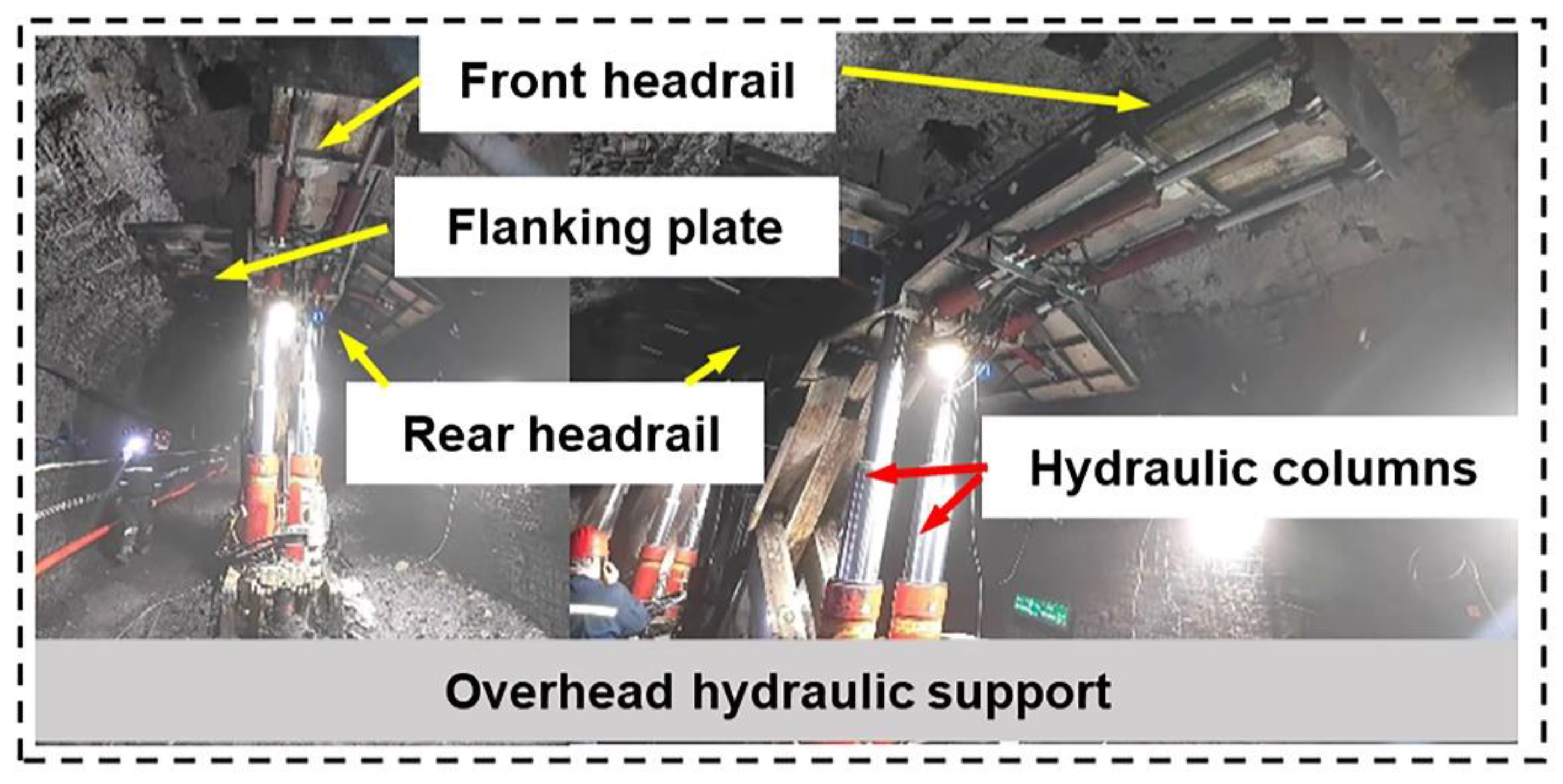
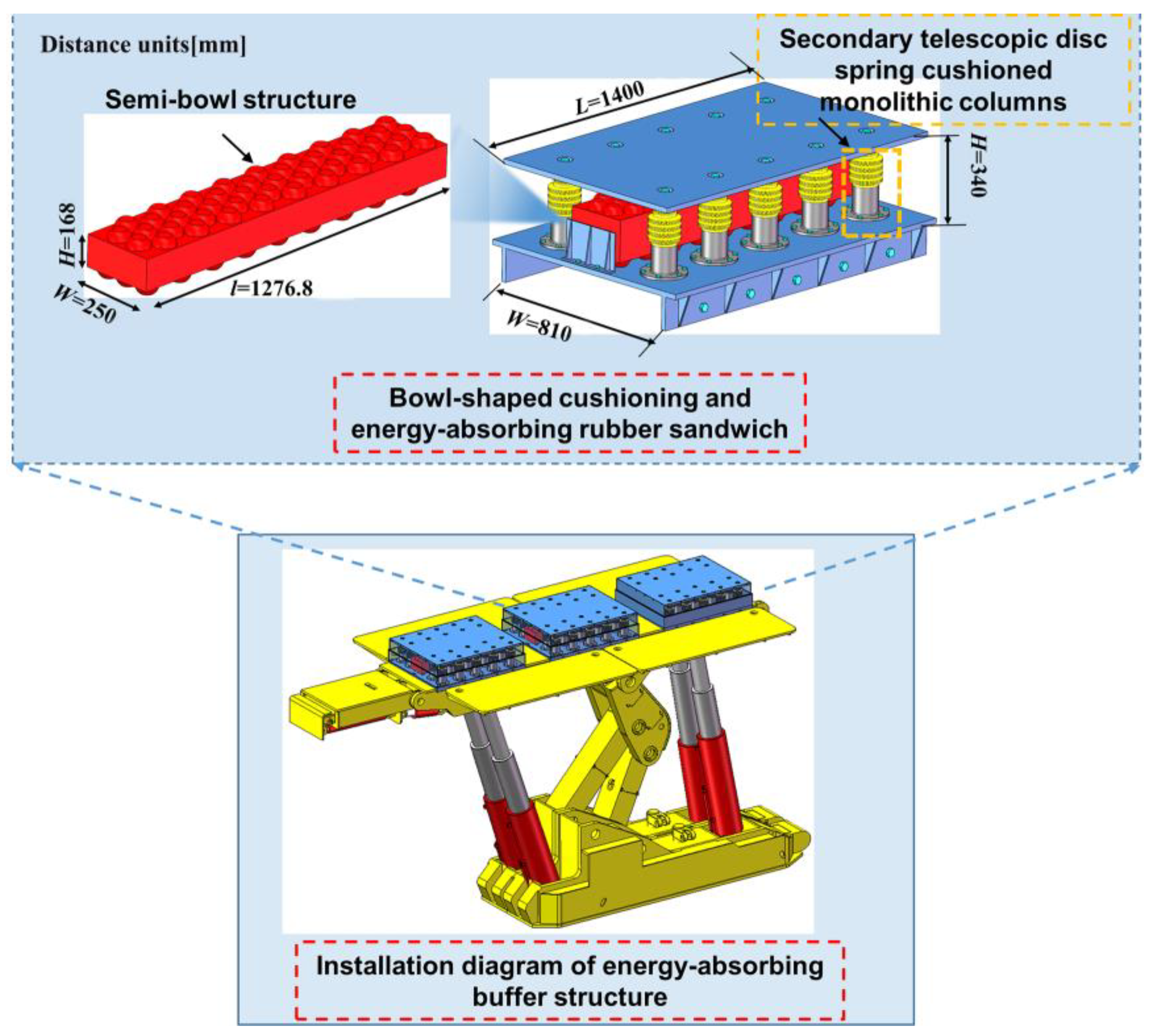
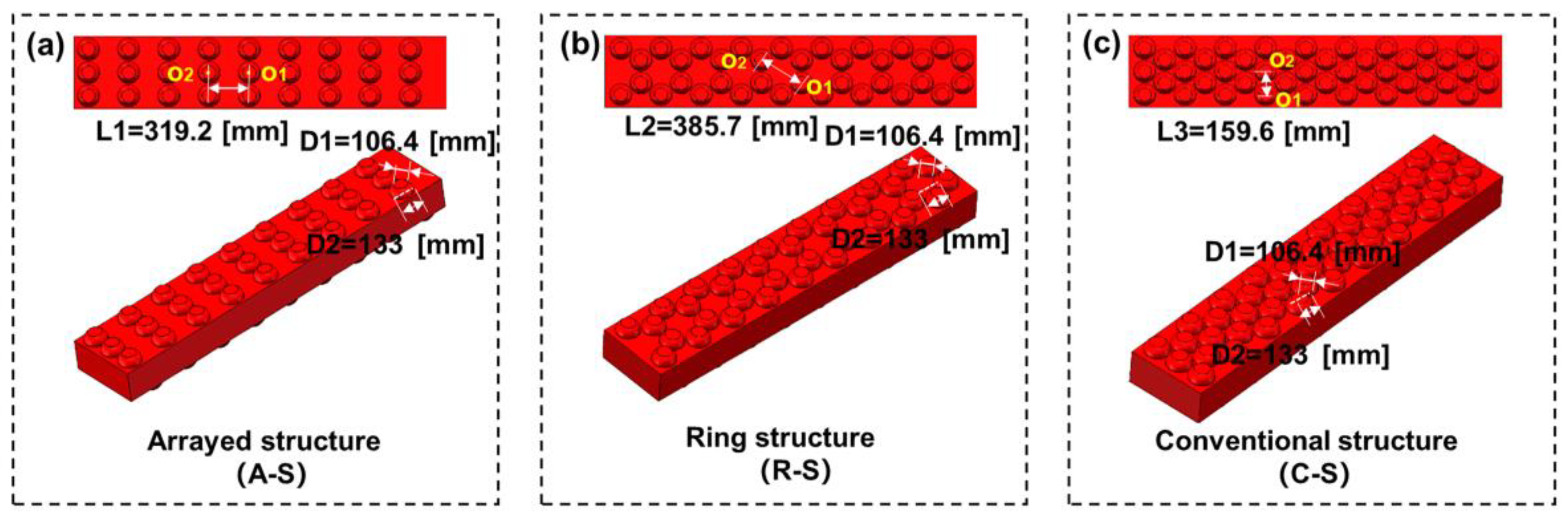
2.1. Bowl-Shaped Cushioning and Energy-Absorbing Rubber Sandwich

Overhead hydraulic supports are mainly used in the synthesized mining face to provide necessary support and protection for the coal-mining machine. From the aspect of force, the front roof beam and rear roof beam of the hydraulic support are the main force components [18], as shown in Figure 1. The pin joints of the front roof beam, as well as the rear roof beam of the hydraulic support, are near the middle support position of the hydraulic support, and the force of the column at the front roof beam is about 4.2 times of that of the column in the middle position, while the force of the column discharged at the rear is about 4.5 times of that of the column in the middle position [19]. The inhomogeneity of the overrun hydraulic support in the force greatly promotes the design of and research into the vibration damping and energy-absorbing structure.
In the field of engineering and technology, especially in environments that need to withstand high levels of shock and vibration, how to effectively absorb and disperse energy has become a key issue. In order to solve this challenge, this paper designs an innovative rubber cushioning and energy-absorbing structure—a rubber energy absorber with a semi-bowl sphere bump structure, as shown in Figure 2. The unique feature of this structure is that its surface is covered with half-bowl spherical projections. These bumps are not simply attached to the rubber substrate but are also precisely calculated and designed to be tightly integrated with the rubber substrate to form a strong and flexible energy-absorbing unit. Each half-bowl bulge can act like a spring and undergo elastic deformation when impacted by an external force, thus converting the impact energy into the elastic potential energy of the rubber and realizing effective energy absorption. The choice of rubber material is also the key to the success of this structure. High-quality rubber material (Qingdao Huaxia Rubber Co., Ltd., Qingdao, China) with excellent elasticity, abrasion resistance, and corrosion resistance was used. This material not only maintains stable performance in extreme environments but also ensures that the raised structure is not easily worn or deformed over a long period of time.
In addition, the design of the half-bowl bulge takes into account the dispersion of energy. When an impact is applied to a particular bulge, its deformation is transferred to the surrounding bulges, forming a continuous energy-absorbing chain. This dispersion mechanism greatly enhances the overall energy absorption capacity of the structure, making it possible to maintain its structural integrity and stability even under high-impact loads. The number and density parameters of the half-bowl ball structure are the key to affecting the rubber damping and energy absorption effect, and the adjustment of the density of the half-bowl ball structure is conducive to analyzing the influence of different structural parameters on the damping and energy absorption effect. Therefore, on the basis of the previous research [20], this paper designed three forms of half-bowl ball rubber interlayers, respectively, as shown in Figure 3. For the convenience of testing, the three structural forms are named as arranged structure (A-S), ring structure (R-S), and conventional structure (C-S). Among them, the C-S structure has been covered in previous studies, and the A-S and R-S structures were formed by transforming the number and arrangement of different half-bowl ball structures, respectively.

2.2. Dynamical Model

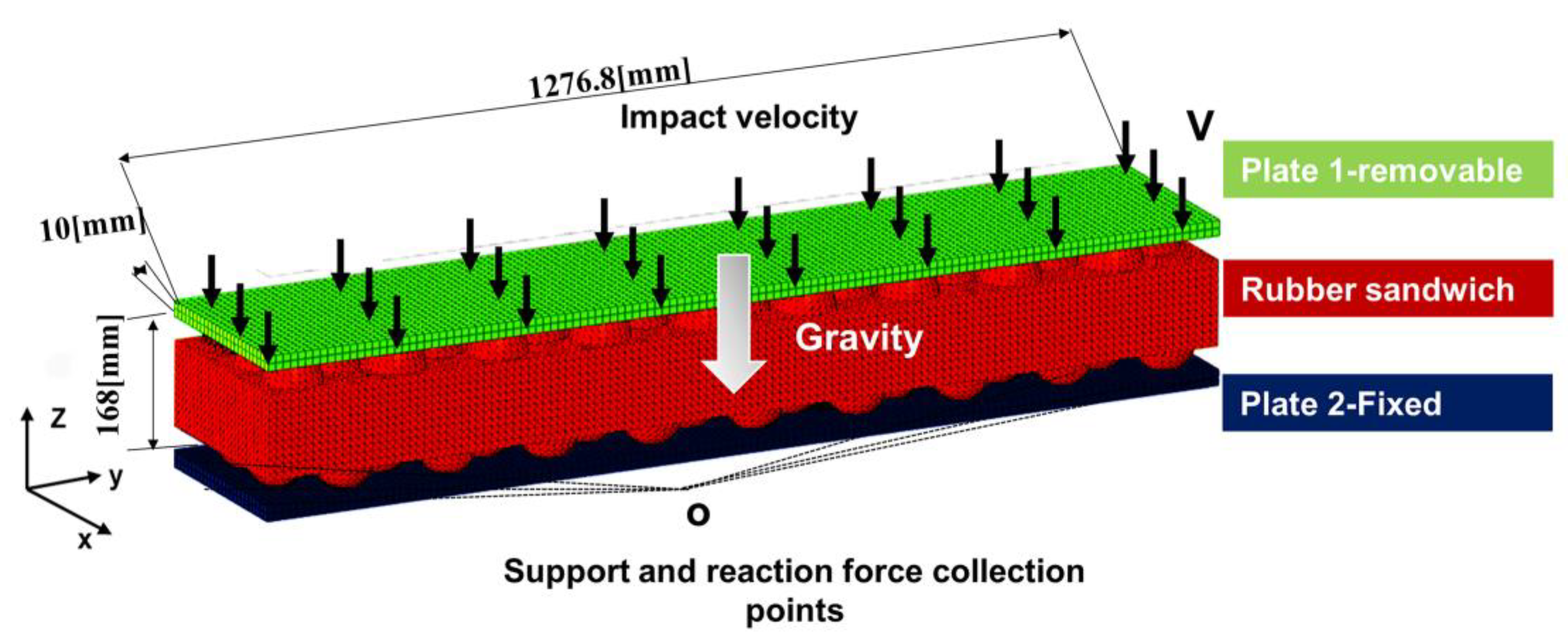
2.2.1. Finite Element Analysis (FEA)

According to the design of the vibration-absorbing structure, the structural model is divided into the upper and lower alloy steel plates and the middle rubber interlayer. The density of the alloy steel structure is 7.82 kg/m3, and the modulus of elasticity is 206 GPa. The density of the rubber is 0.94 kg/m3, the Poisson’s ratio is 0.33, and the modulus of elasticity is 11 MPa.
The finite element analysis of the vibration-damping and energy-absorbing structure was carried out using an explicit dynamic solver, and the equations used to study the nonlinear motion of each node were [21]
M a + f I ( a ) = f E
where M is the mass matrix, a is the phase displacement of the rubber material, i.e., compression displacement, fI is the internal force, and fE is the external force. The compression of the rubber body is calculated as follows [22]:
a t + Δ t = 2 a t a t Δ t + Δ t 2 M 1 ( f E f I ( a ) )
Due to the characteristics of the display calculation method, the accuracy is inversely proportional to the time rather than the length, so it is necessary to focus on the setting of the time step in the recalculation. Due to the limitations of the grid size in the model structure, the transmission distance of the stress waves inside the material cannot exceed the minimum cell length. Also, the number of meshes affects the calculation speed. According to the Courant–Friedrichs–Lewy (CFL) condition, the limiting formula for the time step is [23] as follows:
Δ t f w v
where w is the characteristic cell length of the finite element, v is the velocity of the energy wave in the material, and f is the safety factor ( 1).

2.2.2. Numerical Modeling
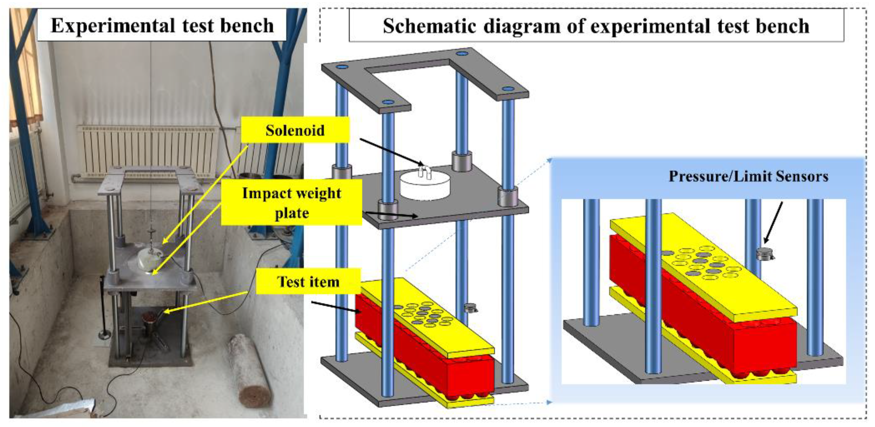
Due to the significant differences in the geological conditions of the rock formations, mine shafts around the world face different challenges in regard to design and operation; additionally, they have specific requirements in terms of the needs and configurations of overburdened equipment. This is particularly true in the Yinchuan region of Ningxia, China. Mines in the Yinchuan area are not only embedded in complex and changing geological environments but are also often accompanied by special geological formations, such as faults, folds, and alternating rock formations of varying hardnesses and stabilities, all of which greatly affect the stability and safety of mine adits.
Considering these geological complexities, the design of mine tunnel support equipment in the Yinchuan area must pay special attention to its ability to withstand impact loads. The mines in the region have complex and variable geologic structures, including rock formations of varying hardnesses, fault zones, and potential groundwater activity. These geologic features directly affect the stability of the trench excavation process as well as the type and intensity of dynamic loads that the support system may face. Through geological exploration and rock mechanics analysis, as well as in-depth communication with frontline workers, the experts assessed the impact energy that could be generated under the most unfavorable geological conditions, ensuring safety margins for the support design. The impact energy that the underground tunnel support system can withstand was clearly defined in the broad but critical range of 104 J–105 J. The impact energy of the underground tunnel support system is defined as 104 J–105 J. At this point, the corresponding range of impact velocities was calculated and determined within the range of impact energies withstood, i.e., impact velocities in the range of 20 m/s–64 m/s, taking into account the effect of equipment gravity. This range of energy not only reflects the extreme geologic stress conditions that may be encountered in the mines in the region but also reflects the extreme geologic stress conditions that may be encountered in the mines in the Yinchuan region. This energy range not only reflects the extreme geologic stress conditions likely to be encountered in mines in the region but also reflects the critical role that support equipment plays in safeguarding the lives of miners and maintaining normal mine production.
In the process of simulation modeling, the influence of mesh density on the calculation accuracy and speed is fully considered. The upper and lower parts of the rubber sandwich have alloy steel plates with uniform texture, and its grid is set as a hexahedral structure with a grid unit of 30. Due to the existence of a half-bowl structure in the rubber sandwich, a tetrahedral structure with a grid density of 20 is set.
According to the actual situation of the roadway, the simulation model is simplified into plate-1, plate-2, and rubber sandwich. Plate-1 is set to move in the vertical direction, plate-2 is a fixed plate, and there is energy transfer inside the rubber sandwich for compression rebound. The impact energy is uniformly applied to plate-1 in the form of velocity, and the rubber sandwich can measure the internal energy change and compression. In order to facilitate the detection of the support and reaction force of plate-2, a support and reaction force concentration point O is set up in advance on the outside of plate-2, as shown in Figure 4.
The nature of the interaction between the rubber sandwich and the plate itself is “general contact” with a friction coefficient of 0.3, whereas hard contact is the normal behavior that penalizes the tangential behavior of the friction equation. In order to reduce the computational cost, the mass scaling method was used to shorten the stabilization time of the explicit solver. In order to reduce the simulation time and to ensure that the loads remain in the quasi-static region without any penetration, the kinetic energy is assumed to be 5% smaller than the internal energy of the structure. The finite element model consists of a split energy-absorbing rubber body and two steel plate samples on the top and bottom. Due to the symmetry of the model, only 1/2 of the energy-absorbing lift and steel plate samples were meshed. Simplified integrated C3D8R brick cells were used for meshing. The cell size of the composite is the same as that of the crystal cell. The upper and lower steel plates were meshed using integer hexahedra, and the model mesh accuracy was set to 60. The rubber body was treated as an isotropic elastomer (the mechanical parameters of the rubber were used in the calculations), and the calculations were carried out using the Explicit Time Integration option in Abaqus /Explicit, with the simulation set to 50 steps. Abaqus uses a local convergence criterion which looks at the force residuals at each node of the model. Abaqus requires that the maximum residual (unbalanced force) at each node in the model is less than or equal to 0.5% of the time-averaged force to accept iterative convergence. This 0.5% is chosen as a reasonable trade-off between quadratic convergence accuracy and efficiency, providing sufficient accuracy for most nonlinear problems.

2.3. Impact Test

As an indispensable theoretical basis for modern engineering design, the accuracy and reliability of simulation results are directly related to the performance and safety of final products. In order to rigorously verify the structural response and energy absorption characteristics predicted by the simulation model, this paper innovatively designs and constructs an efficient and accurate energy-absorbing and shock-absorbing impact test device. The device not only aims to simulate the dynamic impact environment in the real world but also realizes the accurate capture and analysis of key parameters during the impact process by integrating advanced measurement technologies.
The core components of the device include a precision-controlled electromagnet system, a mass-adjustable impact counterweight, and a solid support structure, the stand, as shown in Figure 5. The electromagnet serves as the driving source, and its fast response capability permits the generation of controllable impact energy in a short period of time to simulate impact events of varying speeds and intensities, which is essential for evaluating the impact resistance of the structure under different operating conditions. The design of the electromagnet also takes into account the precise control of the energy release to ensure consistent conditions for each test, thus improving the repeatability and comparability of the test data.

3. Results and Discussion

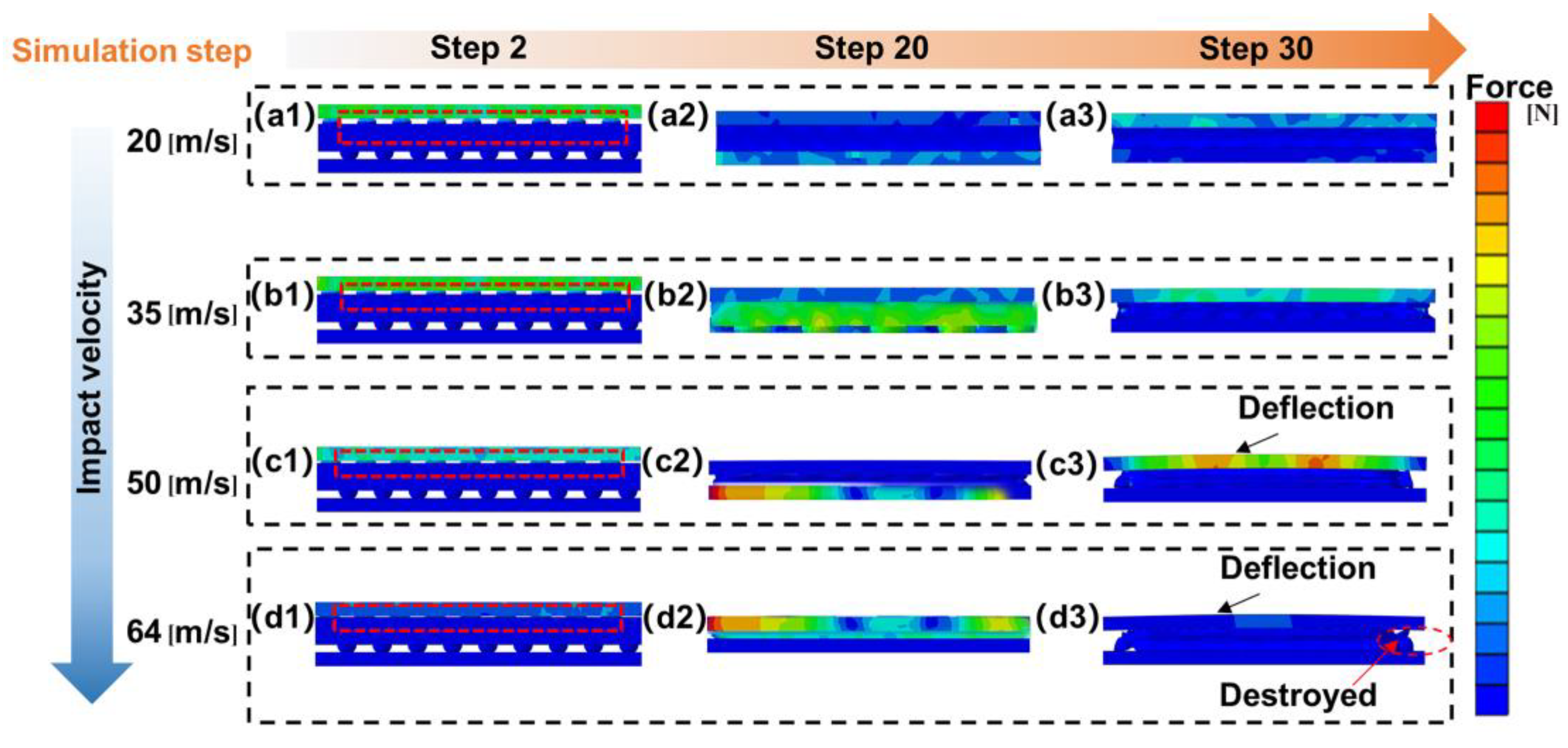
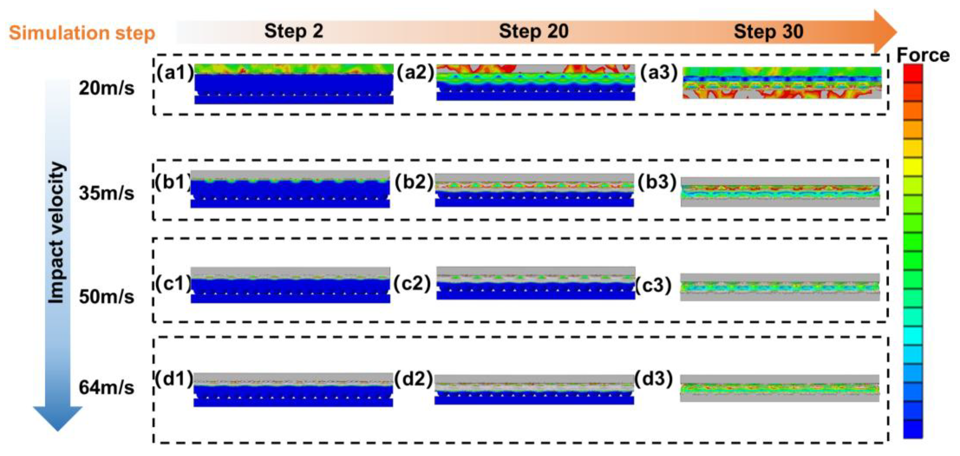
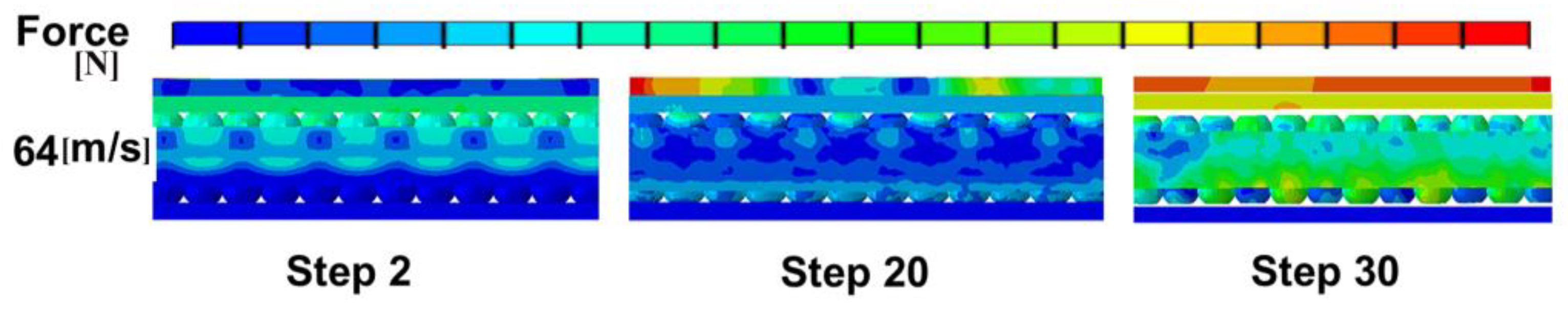
3.1. Simulation Analysis of Rubber Sandwich Under Different Impact Velocities

By simulating the dynamic response of the energy-absorbing damping structure of a half-bowl ball under different impact velocities, a deeper understanding of the performance of the structure under different operating conditions can be achieved. This includes its energy-absorbing capacity, damping effect, and the stability of the structure. This is crucial for the design and optimization of energy-absorbing shock-absorbing structures. In practical applications, the impact velocity may change due to various factors. Through simulation studies, the behavior of energy-absorbing cushioning structures with semi-bowls under different impact velocities can be predicted to provide a basis for evaluating their performance in real-world applications. This helps to ensure that the structure maintains a stable performance in the face of various impacts.
It is mentioned in Section 2.2.2 that the supporting equipment needs to meet the impact energy range of 104 J and 105 J, and, through calculation, the impact speed should be set to 20 m/s to 64 m/s. Therefore, this paper sets the impact speed to 20 m/s, 35 m/s, 50 m/s, and 64 m/s to test the dynamic changes in the structure of the half-bowl ball under different impact speeds. The specific energy–velocity correspondence is shown in Table 1.

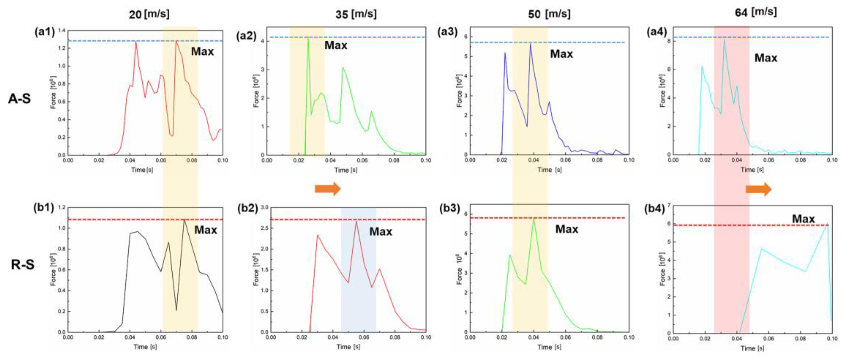
3.1.1. A-S Structural Analysis

Figure 6 shows the dynamic response cloud of the A-S cushioning and energy-absorbing structure at different impact velocities. Overall, the middle rubber sandwich undergoes significant compressive deformation as the simulation step increases. It is analyzed at an impact velocity of 20 m/s, as shown in Figure 6(a1–a3). The figure shows that the plate-1 first contact with the rubber sandwich at the top of the half-bowl ball structure appeared to cause compression deformation, and the bottom of the sandwich also appeared to cause deformation. This indicates that the rubber sandwich is involved in cushioning and energy absorption, and the impact energy follows a top-to-bottom transfer in the cushioning and energy absorption structure and is stored inside the rubber through the deformation of the rubber sandwich.
In addition, at a step size of 30, the pressure of plate-1 is greater than the pressure of plate-2, which indicates that there is a rebound phenomenon in the rubber, as shown in Figure 6(a3). Meanwhile, the compression at the top of the rubber sandwich increases gradually with the increase in the impact velocity, as shown in Figure 6(a1,b1,c1,d1). It is worth noting that, when the impact velocity is 64 m/s, the rubber sandwich at simulation step 30 shows a damage phenomenon, as shown in Figure 6(d3). Meanwhile, the A-S structure shows a bending deformation phenomenon of the top plate-1 at a step size of 30 and at an impact velocity of 50 m/s. This indicates that the compression response of the top of the rubber sandwich is strengthened with the increase in impact velocity, and the compression and resilience of the rubber should be emphasized when setting up the energy-absorbing cushioning device so as not to cause failure of the cushioning device [24].

3.1.2. R-S Structural Analysis

Figure 7 shows the simulation cloud of the R-S structure; the rubber sandwich of the R-S structure still shows the compression and rebound phenomenon with the increase in the impact velocity and the simulation step size, which is determined by the rubber material. However, compared with the simulation of the A-S structure (Figure 6), from Figure 7(a2,b2,c2,d2) it can be found that the bottom of the rubber sandwich is not completely compressed when the step size is 20. At the same time, the transfer of impact energy is slowed down, which is confirmed in Figure 7(a3,b3,c3,d3). There is no damage to the rubber sandwich and no bending deformation of the top plate-1. This indicates that the R-S structure has stronger cushioning stability than the A-S structure, and the half-bowls in the R-S are arranged in a ring pattern (Figure 3b), which makes it easier to absorb the impact energy uniformly, thus avoiding structural damages and anisotropy due to uneven forces [25].

3.1.3. C-S Structural Analysis

Energy-absorbing damping structures are usually designed to absorb and disperse impact energy to mitigate damage to systems or equipment [26,27]. Such structures usually have certain damping properties that can gradually dissipate and slow down the impact energy, thus protecting the system or equipment from impact damage [28]. In the previous study [20], the researchers found that the R-S structure can meet the maximum impact energy, that is, the impact velocity of 64 m/s, when the shock-absorbing structure is stable. Therefore, when the impact velocity is less than 64 m/s, the compression and rebound of the rubber sandwich are in the acceptable range. Here, this paper only takes the simulation cloud diagram of the C-S structure at the maximum impact velocity for analysis and comparison, as shown in Figure 8. From the figure, it can be seen that the pressure of the top plate-1 increases when the simulation step is 20, which indicates that the rubber has begun to rebound at this time, and the half-bowl ball structure in the C-S is filled tightly while reserving the space for its deformation, so the C-S structure fully meets the support requirements. However, compared with R-S, the C-S structure will increase the weight and process cost of the rubber interlayer; therefore, from the dynamic simulation analysis only, it can be concluded that both R-S and C-S can be used for the support work of the target tunnel but that R-S will be more suitable.

3.2. Analysis of Support and Reaction Forces in Energy-Absorbing Structures with Vibration Damping

Overall, there is a fluctuation in the support force in the rubber shock absorber which is mainly caused by the sudden decrease in impact velocity after contact with the guard. Among them, the fluctuation of the A-S center support reaction force curve is more obvious, as shown in Figure 9(a1–a4). At this time, the branch reaction force appears as 3–4 peak points, or even more. In contrast, the peak points of the branch reaction force in R-S will not exceed 4. This phenomenon can prove that the R-S structure has better vibration resistance from the side. In addition, with the increase in shock velocity, the maximum pressure of the shock-absorbing equipment of both structures also increases.
It is worth noting that the maximum pressure of R-S is much lower than that of A-S for the same impact velocity, while the peak of the maximum pressure point is reached later. This strongly suggests that the R-S structure can absorb more energy and can delay the peak pressure. This behavior can provide sufficient time for the opening of the pressure relief valve in the support equipment, thus preventing serious damage to the hydraulic support. In addition, the support reaction force appears at 0.04 s in Figure 9(b4), which is completely different from the other curves. This phenomenon may be due to the ring-type half-bowl-ball structure that forms a cavity at that instant, thus generating an air-supporting force at the center; the structure is shown in Figure 3b.
The sudden decrease in impact velocity as it contacts the guard is the main cause of fluctuations in the support force [29]. Such fluctuations not only reflect the process of absorption and dispersion of impact energy but also reveal the response characteristics of different structures in response to dynamic impacts. The significant fluctuations of the support reaction force curve in the A-S structure (shown in Figure 9) indicate that it has experienced several concentrated releases of energy during the impact process, which may be related to the greater rigidity of the structure and the lack of uniformity of energy dispersion. In contrast, the fluctuation of the branch reaction force in the R-S structure is relatively smooth with fewer peak points, indicating that it can better disperse the impact energy throughout the structure and reduce the local accumulation of energy, thus improving the overall stability and vibration-resistant performance of the structure [30].

3.3. Experimental Validation

The impact test rig can test the support reaction force of a cushioning and energy-absorbing structure. The R-S structure with better simulation effect is selected and its support reaction force is tested at an impact velocity of 64 m/s and compared with the simulation results.
The raw data of the test appeared to fluctuate many times, so this paper is plotted by averaging the data of three tests, as shown in Figure 10. Overall, the trend of comparing the test data with the simulation data is the same. As can be seen from the figure, the test data in the support reaction force appeared more forward in time. The R-S structure can be viewed as a unit cavity composed of multiple half-bowl ball compositions, and it cannot play a full supporting role for the air in the experimental conditions. In addition, the rubber sandwich is more likely to pop the counterweight plate off during the test, when the pressure is instantaneously 0.
In regard to the source of experimental and simulation errors, this mainly comes from the vibration interference of the experimental device, and the micro-deformation of the overall frame will also have an effect on the experimental data. Meanwhile, during the experiment, the rubber energy-absorbing body will have a short suspension state, i.e., the upper and lower plates are popped open and the pressure sensor cannot sense it. In addition, the friction in the device will also affect the impact velocity.

4. Conclusions

In this paper, a simple and effective half-bowl-shaped spherical rubber energy-absorbing structure is proposed and designed based on the impact characteristics of underground coal mining roadways. A coupled analysis model of the buffer energy-absorbing device was established by using Abaqus 6.14, and the influence of different impact speeds on the shock absorption performance of the rubber sandwich was studied. The shock-absorbing characteristics of the support device and its mechanism are revealed by analyzing the pressure cloud diagram and the support reaction force curve. Meanwhile, the impact test platform was utilized for verification. The final conclusions are as follows:
Semi-bowl spherical rubber interlayers in R-S and C-S configurations are available for impact energies of up to 105 J. R-S configurations meet these conditions with the advantages of low costs and ease of processing. Differences in surface structure can lead to differences in cushioning and energy absorption, and the circular arrangement of half-bowls in the R-S structure creates a cushioning and energy absorption cell on the surface which not only transmits the impact energy more uniformly but also provides a certain degree of air support in the cell.Compared to the A-S structure, the R-S structure reduces the maximum pressure value by about 15–35% at different impact velocities. At the same time, the excellent cushioning performance can delay the appearance of the peak of the support reaction force.
The effect of different materials (e.g., rubber with different hardness and density) on the performance of energy-absorbing structures will be further investigated in subsequent studies to find better material combinations to improve energy absorption efficiency and durability. Consideration also needs to be given to the use of composite materials or the addition of reinforcements to improve the strength and wear resistance of the rubber layer. In addition, more complex dynamic impact tests are conducted to simulate more realistic impact conditions (e.g., multiple impacts, impacts in different directions, etc.) in underground coal mine roadways. Changes in the performance of energy-absorbing structures during long-term use, including material aging, fatigue damage, etc., should be evaluated. In addition, underground field tests are needed in the hope that more field data can be used to optimize the energy absorber structure.

Author Contributions

Conceptualization, J.M.; methodology, R.Y. and K.Z.; software, X.M.; validation, C.Z. and M.D.; formal analysis, X.K.; investigation, D.T. and J.M.; resources, L.H.; writing—review and editing, J.M. All authors have read and agreed to the published version of the manuscript.

Funding

This research was funded by the National Natural Science Foundation of China Grant, grant number 52104134, Shandong Province Higher Education Institutions Qingchuang Science and Technology Support Program, grant number 2023KG304, and China Postdoctoral Grant, grant number 2020M682268.

Data Availability Statement

The original contributions presented in this study are included in the article. Further inquiries can be directed to the corresponding author.

Conflicts of Interest

Author Xiangjun Meng and Canguang Zheng was employed by the company Yankuang Energy Group Co., Ltd. Xiangjun Kong was employed by the company Qinghai Energy (Development) Group Co., Ltd. Dan Tian was employed by the company Yankuang Xinjiang Nenghua Co., Ltd. The remaining authors declare that the research was conducted in the absence of any commercial or financial relationships that could be construed as a potential conflict of interest. The company Yankuang Energy Group Co., Ltd., Qinghai Energy (Development) Group Co., Ltd., and Yankuang Xinjiang Nenghua Co.,Ltd. had no role in the design of the study; in the collection, analyses, or interpretation of data; in the writing of the manuscript, or in the decision to publish the results.

Abbreviations

Symbols/AbbreviationsConnotation
A-SArranged structure
R-SRing structure
C-SConventional structure
MMass matrix
aPhase displacement of the rubber material
fIInternal force
fEExternal force
wCharacteristic cell length of the finite element
vVelocity of the energy wave
F()Safety factor (≤1)
FEAFinite element analysis
DEMDiscrete element analysis
R&DResearch and experimental development

References

  1. Yang, Z.K.; Sun, Z.Y.; Jiang, S.B.; Mao, Q.H.; Liu, P.; Xu, C.Z. Structural analysis on impact-mechanical properties of ultra-high hydraulic support. Int. J. Simul. Model 2020, 19, 17–28. [Google Scholar] [CrossRef]
  2. Zhao, T.; Guo, W.; Tan, Y.; Lu, C.; Wang, C. Case histories of rock bursts under complicated geological conditions. Bull. Eng. Geol. Environ. 2018, 77, 1529–1545. [Google Scholar] [CrossRef]
  3. An, H.; Mu, X. Contributions to Rock Fracture Induced by High Ground Stress in Deep Mining: A Review. Rock Mech. Rock Eng. 2024, 1–49. [Google Scholar] [CrossRef]
  4. Zhang, C.; Liu, N.; Chu, W. Key technologies and risk management of deep tunnel construction at Jinping II hydropower station. J. Rock Mech. Geotech. Eng. 2016, 8, 499–512. [Google Scholar] [CrossRef]
  5. Wei, W.; Zhang, F.; Xing, Y.; Wang, H.; Liu, R. Design and Mechanical Properties Analysis of Variable Buffer-Force Planing Energy-Absorbing Device for Rail Vehicles. Appl. Sci. 2023, 13, 1596. [Google Scholar] [CrossRef]
  6. Yumrutas, H.I.; Ozcanan, S.; Apak, M.Y.; Anwer, M.J. Experimental and numerical comparative crashworthiness analysis of innovative renewable hybrid barrier with conventional roadside barriers. Int. J. Crashworthiness 2023, 28, 334–350. [Google Scholar] [CrossRef]
  7. Xiao, L.; Li, S.; Qian, Y.; Chen, D.; Jiang, T. An overview of OTFS for Internet of Things: Concepts, benefits, and challenges. IEEE Internet Things J. 2021, 9, 7596–7618. [Google Scholar] [CrossRef]
  8. Qi, C. Big data management in the mining industry. Int. J. Miner. Metall. Mater. 2020, 27, 131–139. [Google Scholar] [CrossRef]
  9. Cacciuttolo, C.; Guzmán, V.; Catriñir, P.; Atencio, E. Sensor Technologies for Safety Monitoring in Mine Tailings Storage Facilities: Solutions in the Industry 4.0 Era. Minerals 2024, 14, 446. [Google Scholar] [CrossRef]
  10. Ye, Z.; Yan, G.; Wei, Y.; Zhou, B.; Li, N.; Shen, S.; Wang, L. Real-time and efficient traffic information acquisition via pavement vibration IoT monitoring system. Sensors 2021, 21, 2679. [Google Scholar] [CrossRef] [PubMed]
  11. Kang, J.; Wan, D.; Sheng, Q.; Fu, X.; Pang, X.; Xia, L.; Li, D. Risk assessment and support design optimization of a high slope in an open pit mine using the jointed finite element method and discontinuous deformation analysis. Bull. Eng. Geol. Environ. 2022, 81, 254. [Google Scholar] [CrossRef]
  12. Afzal, M.; Liu, Y.; Cheng, J.C.P.; Gan, V.J. Reinforced concrete structural design optimization: A critical review. J. Clean. Prod. 2020, 260, 120623. [Google Scholar] [CrossRef]
  13. Zhang, K.; Zhang, Y.; Zhang, S.; Ren, J.; Zhang, L.; Zhang, R.; Cui, Y. Study on the energy evolution mechanism of coal and rock with impact tendency under different strain rates. Sci. Rep. 2023, 13, 13773. [Google Scholar] [CrossRef] [PubMed]
  14. Li, Y.; Zhang, H.; Xie, J.; Xiao, S.; Zhu, T.; Zhou, G.; Xu, L. Energy absorption characteristics and parameter optimization of anti-climb energy-absorbing devices for subway vehicles under impact loads. Appl. Sci. 2024, 14, 5203. [Google Scholar] [CrossRef]
  15. Isaac, C.W.; Duddeck, F. Recent progress in 4D printed energy-absorbing metamaterials and structures. Virtual Phys. Prototyp. 2023, 18, e2197436. [Google Scholar] [CrossRef]
  16. Wang, S.; Su, S.; Zhao, Q.; An, D.; Xiao, Y.; Xu, H. Study on the Support Effect of Energy-Absorbing Support Structure in the Coal Mine Roadway and the Synergic Effect with Wall Rock. Shock Vib. 2023, 2023, 6673458. [Google Scholar] [CrossRef]
  17. Li, G.; Ma, F.; Guo, J.; Zhao, H.; Liu, G. Study on deformation failure mechanism and support technology of deep soft rock roadway. Eng. Geol. 2020, 264, 105262. [Google Scholar] [CrossRef]
  18. Zeng, Q.; Li, Z.; Wan, L.; Ma, D. Study on Roof Instability Effect and Bearing Characteristics of Hydraulic Support in Longwall Top Coal Caving. Appl. Sci. 2023, 13, 8102. [Google Scholar] [CrossRef]
  19. Cao, D.; Chen, H.; Yuan, J. Inline force on human body due to non-impulsive wave overtopping at a vertical seawall. Ocean Eng. 2021, 219, 108300. [Google Scholar] [CrossRef]
  20. Ma, J.; Xiao, Y.; Ma, B.; Zheng, C.; Hu, X.; Tian, D.; Du, M.; Zhang, K. Research on the Energy-Absorbing and Cushioning Performance of a New Half-Bowl Ball Rubber Body in Tunnel Support. Processes 2024, 12, 1981. [Google Scholar] [CrossRef]
  21. Dai, K.; Fang, C.; Zhang, S.; Shi, Y. Conceptual design and numerical study on a cable-based energy dissipating system for the vibration reduction of tower-like structures. Eng. Struct. 2021, 237, 112034. [Google Scholar] [CrossRef]
  22. Bustamante, R.; Rajagopal, K.R. A new type of constitutive equation for nonlinear elastic bodies. Fitting with experimental data for rubber-like materials. Proc. R. Soc. A 2021, 477, 20210330. [Google Scholar] [CrossRef]
  23. Kowalczuk, Z.; Tatara, M.S. Analytical ‘steady-state’-based derivation and clarification of the courant-friedrichs-lewy condition for pipe flow. J. Nat. Gas Sci. Eng. 2021, 91, 103953. [Google Scholar] [CrossRef]
  24. Long, S.; Yao, X.; Wang, H.; Zhang, X. Failure analysis and modeling of foam sandwich laminates under impact loading. Compos. Struct. 2018, 197, 10–20. [Google Scholar] [CrossRef]
  25. Sabah, S.H.A.; Kueh, A.B.H.; Al-Fasih, M.Y. Bio-inspired vs. conventional sandwich beams: A low-velocity repeated impact behavior exploration. Constr. Build. Mater. 2018, 169, 193–204. [Google Scholar] [CrossRef]
  26. Almajhali, K.Y.M. Review on passive energy dissipation devices and techniques of installation for high rise building structures. Structures 2023, 51, 1019–1029. [Google Scholar] [CrossRef]
  27. Hu, S.; Zhu, S.; Wang, W.; Alam, M.S. Structural and nonstructural damage assessment of steel buildings equipped with self-centering energy-absorbing rocking core systems: A comparative study. J. Constr. Steel Res. 2022, 198, 107559. [Google Scholar] [CrossRef]
  28. Xu, G.; Guo, T.; Li, A.; Wang, S.; Zhang, R.; Zhu, R.; Xu, J. Review on self-centering damper for seismic resilient building structures. Structures 2023, 54, 58–77. [Google Scholar] [CrossRef]
  29. Dsouza, H.; Pastrana, J.; Figueroa, J.; Gonzalez-Afanador, I.; Davila-Montero, B.M.; Sepúlveda, N. Flexible, self-powered sensors for estimating human head kinematics relevant to concussions. Sci. Rep. 2022, 12, 8567. [Google Scholar] [CrossRef] [PubMed]
  30. Łupieżowiec, M.; Rybak, J.; Różański, Z.; Dobrzycki, P.; Jędrzejczyk, W. Design and construction of foundations for industrial facilities in the areas of former post-mining waste dumps. Energies 2022, 15, 5766. [Google Scholar] [CrossRef]
Figure 1. Overhead hydraulic support in the form of a roadway.
Processes 12 02895 g001
Figure 2. Installation of a half-bowl ball shock-absorbing rubber sandwich and its overall structure.
Processes 12 02895 g002
Figure 3. Three forms of half-bowl ball rubber sandwich. (a) Arrayed structure. (A-S), (b) ring structure (R-S), and (c) conventional structure (C-S).
Processes 12 02895 g003
Figure 4. Simulation model of the energy-absorbing device of the half-bowl ball.
Processes 12 02895 g004
Figure 5. Experimental test bench and its schematic diagram.
Processes 12 02895 g005
Figure 6. Dynamic response cloud of the A-S cushioning and energy-absorbing structure at different impact velocities: (a1a3) 20 m/s, (b1b3) 35 m/s, (c1c3) 50 m/s and (d1d3) 64 m/s.
Processes 12 02895 g006
Figure 7. Dynamic response cloud of the R-S cushioning and energy-absorbing structure at different impact velocities: (a1a3) 20 m/s, (b1b3) 35 m/s, (c1c3) 50 m/s and (d1d3) 64 m/s.
Processes 12 02895 g007
Figure 8. Dynamic response cloud of the C-S cushioning and energy-absorbing structure at impact velocities of 64 m/s.
Processes 12 02895 g008
Figure 9. Support reactions in A-S and R-S structures for different impact velocities: (a1a4) is the support reaction force of A-S structure at impact velocities of 20 m/s, 35 m/s, 50 m/s and 64 m/s, (b1b4) is the support reaction force of R-S structure at impact velocities of 20 m/s, 35 m/s, 50 m/s and 64 m/s.
Processes 12 02895 g009
Figure 10. Comparison of the simulation and experimental data of R-S structure at an impact velocity of 64 m/s.
Processes 12 02895 g010
Table 1. The correspondence between impact energy and velocity.
Impact Energy [J]1 × 1044 × 1047 × 1041 × 105
Speed [m/s]20355064
Disclaimer/Publisher’s Note: The statements, opinions and data contained in all publications are solely those of the individual author(s) and contributor(s) and not of MDPI and/or the editor(s). MDPI and/or the editor(s) disclaim responsibility for any injury to people or property resulting from any ideas, methods, instructions or products referred to in the content.

