Review

A Review of Intelligentization System and Architecture for Ultra-Precision Machining Process

1
Guangdong Provincial Key Laboratory of Micro/Nano Optomechatronics Engineering, College of Mechatronics and Control Engineering, Shenzhen University, Nan-hai Ave 3688, Shenzhen 518060, China
2
Shenzhen Key Laboratory of High Performance Nontraditional Manufacturing, College of Mechatronics and Control Engineering, Shenzhen University, Nan-hai Ave 3688, Shenzhen 518060, China
3
School of Mechanical Engineering and Automation, Harbin Institute of Technology, Shenzhen 518055, China
*
Author to whom correspondence should be addressed.
Processes 2024, 12(12), 2754; https://doi.org/10.3390/pr12122754
Submission received: 1 November 2024 / Revised: 26 November 2024 / Accepted: 30 November 2024 / Published: 4 December 2024

Abstract

:
The intelligence of ultra-precision machining processes has become a research focus in the field of precision and ultra-precision manufacturing. Scholars have conducted some fragmented studies on the intelligence of ultra-precision machining processes; however, a systematic review and summary of the intelligent systems and architectures for such processes are still lacking. Therefore, this paper is devoted to reviewing the intelligent systems and architectures for ultra-precision machining processes, focusing on three aspects: machining environment monitoring, cutting process analysis, and intelligent machining system frameworks. The paper first provides an overview of environmental intelligence monitoring from the perspective of the machining environment and then discusses and summarizes monitoring processes, such as tool errors, tool wear, tool setting, and surface measurement, from the perspective of machining process analysis. The intelligent machining system framework is then analyzed and summarized from the perspective of process control. Finally, the paper outlines the overall framework of the intelligent system for ultra-precision machining processes and analyzes its components. This paper provides guidance for the development of intelligent systems in ultra-precision machining processes.

1. Introduction

Ultra-precision machining technology enables the fabrication of optical components with nonmetric-level surface roughness and sub-micron-level form accuracy, making it widely applied in high-end technological fields, such as the national defense industry, aerospace, bioengineering, and medical devices [1,2,3]. Therefore, it has become one of the key methods for producing high-precision optical components and microstructures with high practical value. Ultra-precision machining technology, primarily centered on single-point diamond turning at the time, was first proposed in the United States in the 1950s [4,5,6]; it gradually spread to other countries and evolved into a comprehensive technology encompassing ultra-precision turning, grinding, polishing, and specialized machining [7,8,9]. Despite several decades of development, ultra-precision machining technology has yet to achieve full automation. Nowadays, the application of intelligent systems in ultra-precision grinding [10] provides a reference for the intelligence of other ultra-precision machining, such as ultra-precision cutting, because intelligent systems employ advanced signal processing algorithms, such as backpropagation (BP) algorithms, multiple neural networks, and machine learning, to handle signals and utilize Internet of Things (IoT) technologies for hierarchical and layered control, significantly enhancing process monitoring and precision control.
As mentioned earlier, the application of intelligent systems in ultra-precision machining processes can be categorized into two main research areas. First and most importantly, intelligent monitoring is a crucial component of the structure of intelligent systems, enabling real-time monitoring of the entire ultra-precision machining process [10]. In the past, attention has been focused on achieving intelligent monitoring of energy consumption in machine tools; this is because traditional methods for energy efficiency monitoring typically rely on dynamometers to measure cutting power to infer the energy efficiency of machine tools [11]. However, such methods are inefficient in monitoring and clearly do not align with the trend of intelligent development in machine tools. Through continuous research, some scholars have integrated sensors into the machining processes of machine tools for intelligent monitoring of their operational states, such as sensors used to monitor the running status of machine tool spindles [12], and intelligent monitoring systems for ultra-precision machining processes have been developed [13]. Building on these advancements, Shi et al. [14] established an online monitoring platform for CNC machine tool states, integrating it into CNC machines to collect sensor signals during cutting processes for real-time analysis, thereby achieving real-time monitoring of machining precision. As the purpose of monitoring is to control machine tools better, Li et al. [15] put forward a hierarchical structure for intelligent monitoring technology of CNC machine tool processes, along with a three-dimensional simulation platform; this approach enables real-time acquisition of machine state information, assessment of operational status, and issuance of control commands to regulate machine operations. Consequently, intelligent monitoring can be applied to manufacturing, achieving effective monitoring outcomes.
Moreover, IoT technology is the technical guarantee for realizing intelligent system building. Liu et al. [16] put forward an intelligent networked machine based on IoT technology, which consists of four parts—a CNC machine, a data acquisition device, a machine network twin, and an intelligent human–machine interface—and it can realize the transmission of information and optimization of the machining paths of a group of CNC machines to each other. Furthermore, Yang et al. [17] based the combination of IoT technology and visualization technology to comprehensively analyze the machining process and make the control of intelligent systems more visual. In addition, as the functionality of the processing equipment continues to improve, Zhang et al.’s [18] idea of optimizing process performance by automatically adjusting processing parameters through a monitoring system is worth investigating. Therefore, IoT technology can realize the control of the machining process, which is the technical guarantee for constructing an intelligent system.
All in all, intelligent monitoring and IoT technology facilitate the automation and intelligence of ultra-precision machining processes. For instance, Dai et al. [19] put forward the theory of automatic identification of center error, Zhang et al. [20] put forward the automatic monitoring system of tool wear, Wang et al. [21] put forward the spindle dynamic balance automatic adjustment method, Jang et al. [22] put forward the method of using an optical instrument to realize the tool setting, and Ni et al. [23] put forward the use of ultrasonic vibration to assist in optimizing the ultra-precision machining process. Although research on the intelligence of ultra-precision machining processes has made preliminary progress, a systematic review and synthesis of the relevant knowledge is still lacking. Therefore, this paper is devoted to providing a systematic review of intelligent systems and architectures for ultra-precision machining processes, focusing on intelligent expertise in environmental monitoring, machining processes, and intelligent machining system frameworks. Building on this, the paper outlines the architecture and components of intelligent systems for ultra-precision machining processes. This paper integrates existing research to outline the architecture of an intelligent system for ultra-precision machining processes following the process shown in Figure 1. The remainder of this paper will first provide an overview of intelligent environmental monitoring in machining, followed by a review of intelligent machining processes and a summary of the intelligent framework for machining systems; finally, the intelligent system architecture for ultra-precision machining processes will be detailed. This paper provides a reference for realizing intelligent systems in ultra-precision machining processes.

2. Intelligent Monitoring of Machining Environment

2.1. Machining Environmental Factors

The precision of ultra-precision machining is often affected by environmental factors, such as vibration, temperature, humidity, cleanliness, and noise, necessitating rigorous monitoring of these factors. Traditional monitoring methods are complex and have poor accuracy, resulting in suboptimal monitoring outcomes; consequently, intelligent monitoring, characterized by real-time and precise monitoring, has emerged as a focal point in manufacturing research. Intelligent monitoring of the machining environment mainly involves using computers to analyze environmental data, achieving real-time monitoring and feedback compensation [34]. Scholars have conducted research on the intelligent monitoring of these environmental factors. For example, Unver et al. [35] utilized machine learning methods for intelligent vibration monitoring; Kesriklioglu et al. [36] implemented real-time temperature data collection and monitoring of the machining process using thermocouples; and Nasir et al. [37] applied wavelet transforms and adaptive neural networks for intelligent monitoring of machining sounds. However, current research primarily focuses on intelligent monitoring of vibration and temperature.
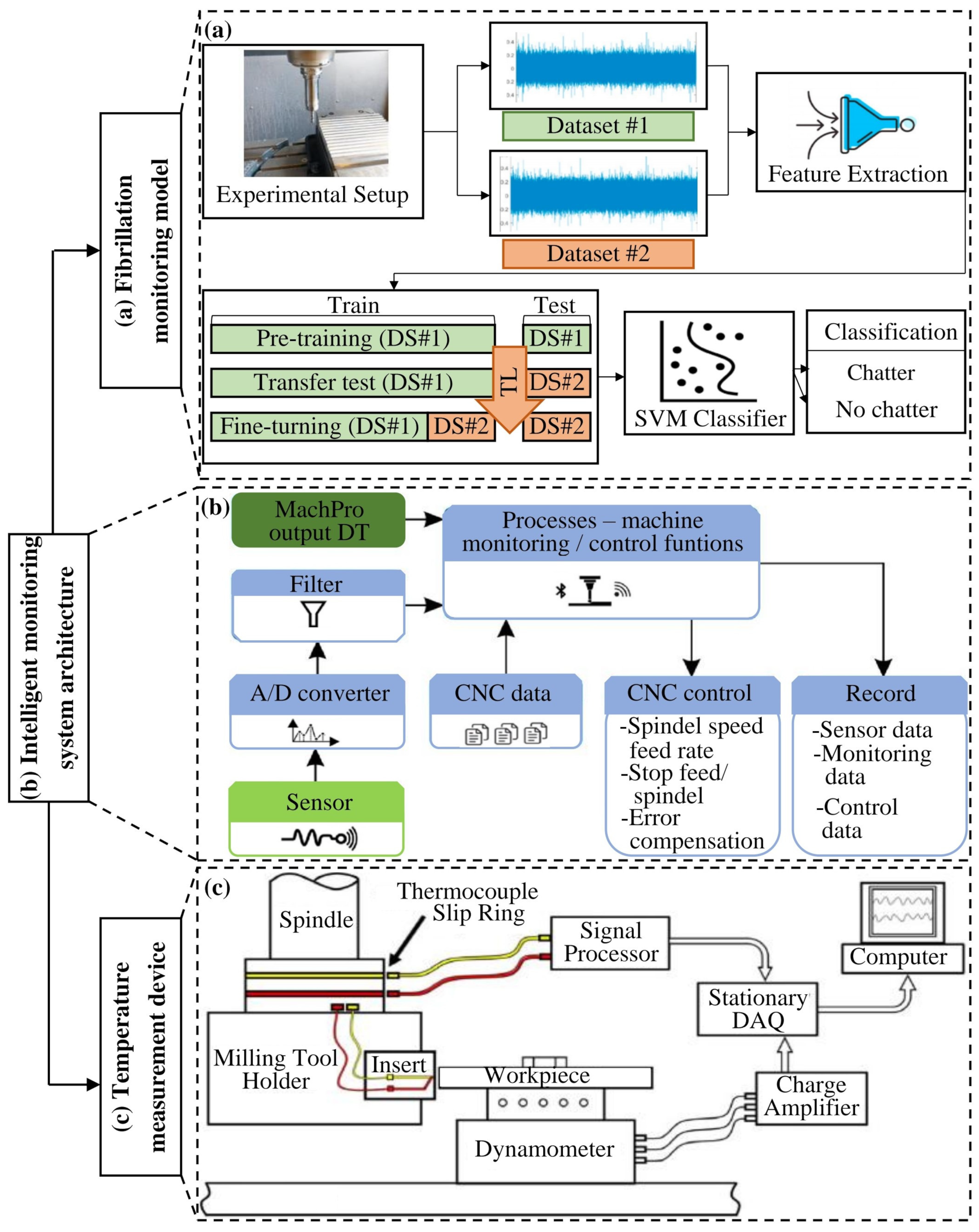
Although initial progress has been made in the intelligent monitoring of vibration and temperature, there remains a need for systematic organization and summarization of this knowledge. Therefore, this paper builds upon intelligent monitoring methods to organize the knowledge of intelligent monitoring systems for the machining environment, ultimately forming the intelligent environmental monitoring structure as depicted in Figure 2. Figure 2a illustrates a vibration monitoring system composed of sensors and algorithm models; it operates by collecting vibration signal data, training a transfer learning algorithm model, and obtaining a trained model for predicting and monitoring vibrations in real time. Figure 2b presents the architecture of an intelligent monitoring system based on the entire machining environment; it employs sensors to gather signals from the monitored object, analyzes and processes these signals to detect environmental changes, and takes corresponding measures to ensure the stability of the machining environment. Figure 2c depicts a temperature monitoring system integrating built-in sensors with computers; it involves embedding thin-film thermocouples on cutting tools to collect data and uses computers for data analysis to achieve real-time monitoring and feedback compensation. In the intelligent monitoring process, the use of IoT technology to realize the perception of the environment has been successively applied to the machining process, and this method creates an interconnection between people and the environment, machines and the environment, and people and machines [38]. This method can realize intelligent sensing of the machining environment and real-time control and adjustment to realize the optimization of the machining environment. Thus, this paper will delve into the structure of intelligent monitoring of machining environment systems concerning vibration and temperature.

2.2. Vibration Monitoring

During ultra-precision machining, vibrations can lead to instability in cutting forces, resulting in machining errors and degraded surface quality, including increased surface roughness. Additionally, vibrations may cause irregular contact between the tool and the workpiece, introducing micro-scale machining errors and potentially leading to surface damage or micro-cracking. Furthermore, vibrations can also affect the geometric accuracy of the workpiece and reduce the stability of the machining process.
Since the magnitude of vibration directly affects machining accuracy, vibration needs to be monitored; the current common monitoring method is to use mechanical vibration isolation; the main principle of mechanical vibration isolation is that according to the source of vibration, the use of vibration-balancing components can effectively balance the size of the vibration so that the vibration tends to balance the state. Based on this principle, Yang et al. [40] developed a vibration isolation system explicitly designed for an ultra-precision machine with an automatic leveling function by using the structure and principle of a traditional air spring vibration isolation system since this system adopts a mechanical vibration isolation design. This system was tested and found to have good vibration isolation performance. However, the uncontrollable nature of this traditional vibration isolation device is why the researchers found that designing new components could also balance the vibrations. Law et al. [41] achieved machine vibration isolation by developing a novel electro-hydraulic actuator that attenuates and isolates the machine’s ground motion to keep the dynamic excitation transmitted to the machine below the allowable level. Pour et al. [42] used an intelligent magnetic current damper to achieve semi-automatic control of the chattering vibration of a machine to identify the vibration generated during machining and to optimize the machining path. Semi-automatic control devices can effectively regulate vibration, but this method’s control process is complicated and unstable.
Although the mechanical vibration isolation method can effectively stabilize the mechanical system, it has a low vibration isolation effect, and it is not easy to adjust the vibration magnitude; hence, it is unsuitable for vibration control in the machining process. With the emergence of sensors, the indirect vibration monitoring method also gradually appeared and has been applied to the field of machining. This method usually entails using sensors to collect cutting signals after processing them through the algorithmic system or identification model; finally, the corresponding mapping equations are established, and the monitoring object’s analysis results are obtained. Consequently, indirect vibration monitoring methods can effectively achieve feedback and vibration control.
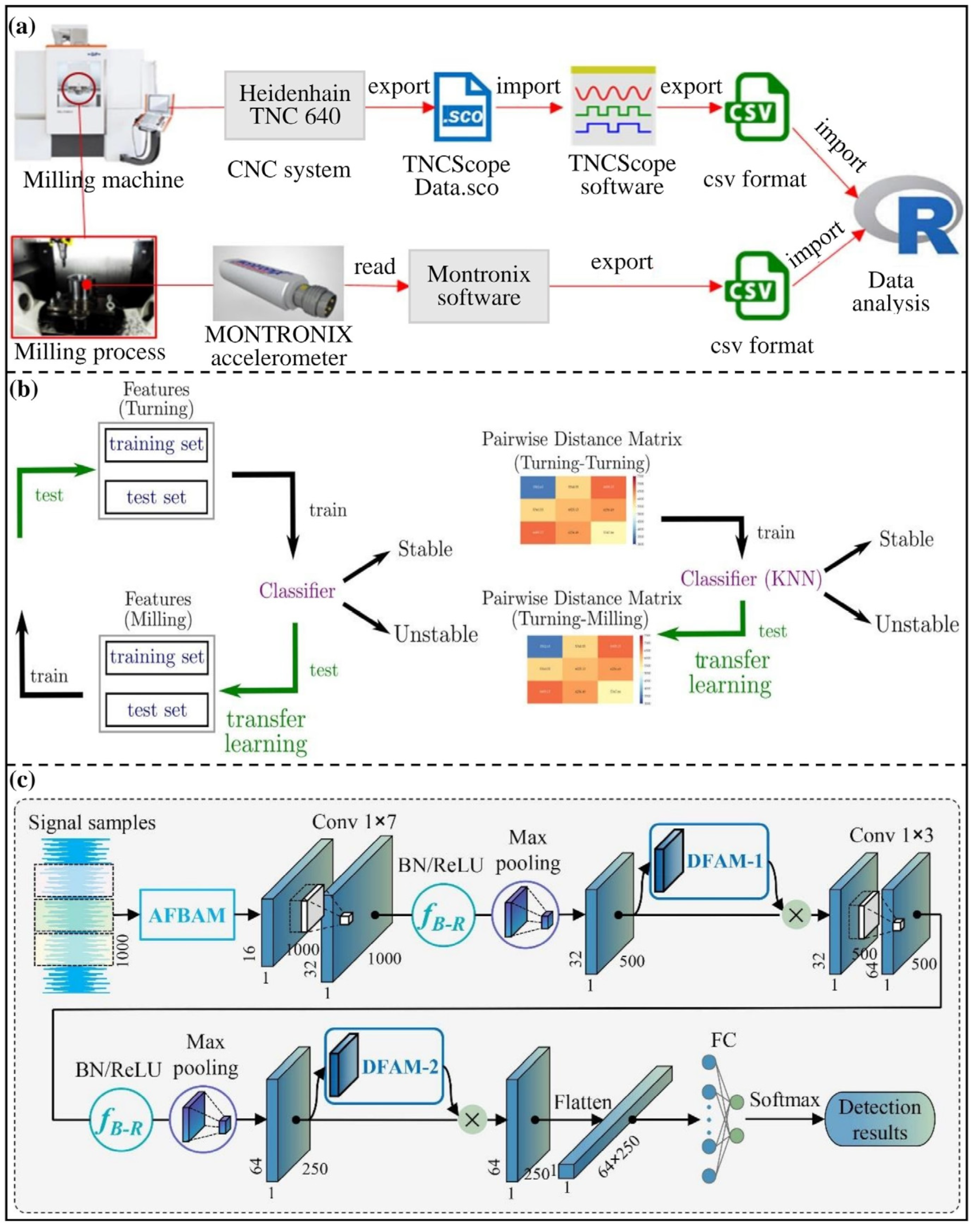
The main principle of indirect vibration monitoring methods involves utilizing signal media to reflect the magnitude of vibrations; through algorithmic systems indirectly, vibrations are controlled and adjusted; the vibration monitoring framework is illustrated in Figure 3. Figure 3a illustrates a vibration signal analysis model during machining processes, where sensors capture vibrations generated by machine tools. These signals are input into corresponding software for data analysis. Figure 3b presents a transfer learning algorithm model constructed for signal recognition, employing training and testing models to adjust the vibration process. Figure 3c depicts the vibration online monitoring framework built with a noise-resistant convolutional neural network; it preprocesses signals to eliminate noise and interference before inputting them into a neural network for layered computations, yielding accurate identification results. Previous studies have widely acknowledged the applicability of algorithms in vibration monitoring, and, thus, this review provides an overview of vibration monitoring based on the framework depicted in Figure 3.
Firstly, a vibration size identification model can be established through the cutting force signal, just as Li et al. [43] built a vibration identification system through a cutting force signal to realize the online identification of vibration in the machining process. The results of identification are analyzed to derive a relationship between the feed and machine vibration [44,45]. Secondly, the algorithm is the basis for ensuring the efficient running of the vibration monitoring system and one of the primary methods for processing the data. Zheng et al. [46] researched the Kalman filtering algorithm based on IoT technology; this filtering method removes the noise signals during processing and analyzes the collected vibration signals to obtain the required data. Finally, a vibration monitoring system is formed by combining a vibration identification model and an algorithmic system, as in the real-time vibration monitoring system proposed by Liang et al. [47]; this monitoring system efficiently realizes real-time control and regulation of vibration through sensors and data processing algorithms, and considering the visualization of vibrations, Bahr et al. [48] developed a system combining vibration monitoring and visual recognition techniques using piezoelectric accelerometers to monitor the vibration signals online to analyze the tool’s working condition.
In the ultra-precision machining process, establishing a reasonable online vibration monitoring system can help real-time monitoring of the machining process, real-time adjustment of machining parameters, real-time inspection of machining quality, and real-time prediction of machining condition to achieve remote monitoring of the machining environment [49,50]. Especially when the machine tool has vibrations for a long time, a reasonable online vibration monitoring system can realize early warning and vibration adjustment [51,52]. Despite the complexity of intelligence, current research has yet to develop intelligent vibration monitoring technology; however, the emergence of online vibration monitoring technology has laid the foundation for studying intelligent vibration monitoring. Therefore, through the above summary, it is evident that the online vibration monitoring system combines vibration monitoring processes with artificial intelligence algorithms for the fusion and exchange of various data, allowing for human–computer interaction, and this system can better control the impact of vibration, increase the stability of the machining system, and guarantee a quality machining process.
Figure 3. Vibration monitoring block diagram: (a) Vibration recognition model based on CNC system signals [53]. Reproduced with permission from author, Mechanical Systems and Signal Processing, Elsevier, 2023. (b) Vibration monitoring model based on transfer learning algorithm [54]. Reproduced with permission from author, Journal of Manufacturing Processes, Elsevier, 2022. (c) Vibration monitoring block diagram based on the anti-noise convolutional neural network [55]. Reproduced with permission from author, Mechanical Systems and Signal Processing, Elsevier, 2024.
Processes 12 02754 g003

2.3. Temperature Monitoring

Ultra-precision machining increases the cutting temperature in the machining zone. High temperatures can exacerbate tool wear, shorten tool life, and degrade the surface quality of the workpiece, such as increased surface roughness and thermal deformation. Furthermore, excessive temperatures may cause thermal softening of the material, altering the geometric accuracy of the workpiece and increasing machining errors. Additionally, high temperatures can induce thermal stresses, leading to micro-cracking and surface damage, which ultimately reduces machining quality, which is not allowed for ultra-precision machining processes. Toshimichi et al. [56] found that cutting heat will deform the workpiece and affect the machining accuracy. Thus, cutting heat needs to be monitored. Since heat and temperature have a direct relationship, heat monitoring can be realized by establishing a temperature monitoring system.
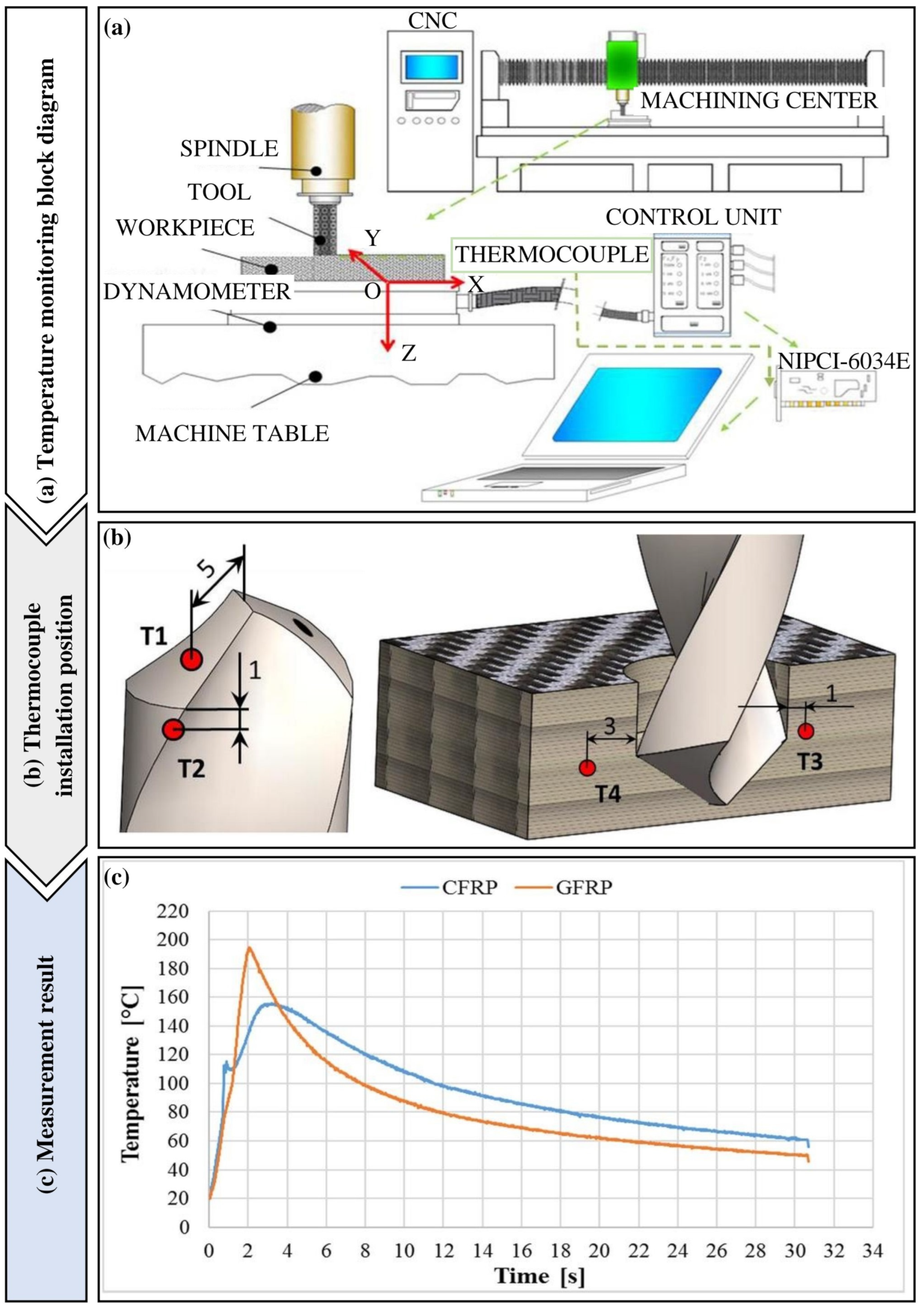
In a temperature monitoring system, the location of the heat source needs to be determined to achieve accurate temperature measurement. Liang et al. [57] used the thermal displacement correlation method to thermally optimize the heat generated by the machining process to find the distribution of heat sources; based on determining the distribution of heat sources, thermocouples are usually used to measure the tool temperature. Building on this, Sorrentino et al. [58] proposed a temperature monitoring system. The temperature monitoring system for the drilling process shown in Figure 4 involves embedding thermocouples in the drilling tool, using the NIPCI-6034E data acquisition card to collect temperature data, and analyzing the data in real time using a computer. Similarly, this method can be applied to ultra-precision machining for real-time temperature monitoring. First, thermocouples are placed on the rake face of the diamond tool, followed by the use of a data acquisition card to collect temperature data. Finally, temperature data are analyzed using a computer, enabling appropriate cooling measures to be taken when cutting temperatures exceed optimal limits. In Figure 4c, the temperature–time curve measured by thermocouple T1 during the drilling of CFRP and GFRP is shown when the drilling speed is 251.2 m/min and the feed rate is 0.1 mm/rev. From the graph, it is evident that during the drilling process, the temperature increases over time, reaching a maximum value. The maximum temperature for CFRP is 155 °C, while for GFRP, it reaches 195 °C. After the drilling is completed, the temperature begins to decrease over time. However, due to the high temperature of the drilling tool, the temperature does not immediately return to ambient conditions after drilling is finished. In addition, online monitoring of the thermoelectric potential between the tool and the workpiece can be well realized using the collector flow set or brush device proposed by Quan et al. [59].
Based on the temperature monitoring system connection frame shown in Figure 4a, it is known that the thermocouples are embedded in the tool’s outer surface, which affects the accuracy of the tool temperature measurement. Thus, temperature measurement accuracy can be improved by embedding thermocouples inside the tool. For example, Li et al. [60] realized online monitoring of the tool temperature during the machining process by embedding a thin-film thermocouple inside the tool. This method can collect the temperature data near the cutting edge in real time and obtain the temperature field distribution near the cutting edge of the tool, which is favorable for the temperature control between the tool and the workpiece during the cutting process; however, neither external thermocouples nor built-in thermocouples for temperature measurement meet the requirements of intelligent development. Therefore, by integrating thermocouples, data acquisition cards, and computers to form an intelligent temperature monitoring system, Marinela et al. [61] designed a temperature monitoring system based on the natural thermocouple method, which is capable of real-time measurement of the tool temperature during the machining process, and indirectly monitoring the tool’s working condition.
Ultimately, the purpose of temperature monitoring is to realize temperature compensation and reduce the influence of temperature on the machining process. Reddy et al. [62] designed a compensation module for real-time thermal error based on heat balance theory and integrated it into an ultra-precision lathe to realize the real-time compensation of thermal error in the machining process. After continuous research on intelligent temperature monitoring technology, it has been found that the use of multi-sensor networks can better realize the centralized control and management of temperature in the machining process [35], which is still in the research stage; however, this method promotes the development of intelligent temperature monitoring technology.

3. Intelligent Machining Processes

Ultra-precision machining technology is widely used in the ultra-precision machining of composite materials and high-performance materials because of its high-precision characteristics [63,64]. Along with the development of artificial intelligence, intelligence is an inevitable trend in the development of ultra-precision machining technology. Figure 5 shows the application of artificial intelligence in the machining process. The figure summarizes the steps of the intelligent machining process, in which the advanced perception system [65] and algorithmic network are the main elements that distinguish advanced machining from ordinary machining. From the content of Figure 5, it can be seen that the realization of intelligent processing involves two approaches. The first approach is to use sensors and other signal acquisition instruments to collect, process, denoise, filter, and store physical quantities, then characterize and extract feature values, and finally use machine learning algorithms to build an intelligent monitoring model for result computation. The second approach involves signal acquisition through sensors, followed by signal decomposition using methods such as short-time Fourier transform, and, finally, the construction of a monitoring model using deep learning algorithms, with the computed results being converted online.
Similarly, for the ultra-precision machining process intelligence system, the intelligent machining process is an integral part of this system; the realization of its intelligence can also follow the two paths shown in Figure 5. Therefore, this part about the intelligent machining process will focus on an overview of ultra-precision process intelligence-related technology, including single-point diamond turning center error identification and compensation, tool wear monitoring, dynamic balance adjustment, tool-setting method, and five assisted machining aspects of the analysis, to summarize the role of the different processes on the intelligent system and provide ideas for the intelligent construction and application of the ultra-precision machining process system.

3.1. Error Identification and Compensation

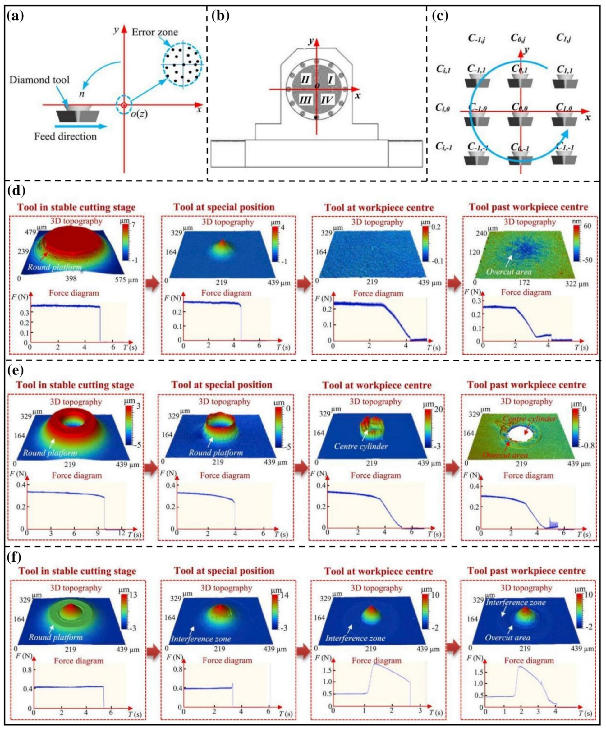
When machining the end face of a workpiece using the single-point diamond turning process, an error zone is formed at the center of the end face of the workpiece, attributable to the precision limitations of the tool-setting instrument and the inadequacy of the tool-setting method. In some studies, it was found that there are nine error conditions [19,67] in this error region, as shown in Figure 6a–c, where Figure 6a is the error region shown at the tool feed end, Figure 6b is the error region summarized at the machined surface of the workpiece, and Figure 6c is the expression of the two-dimensional tool-center-error. In these nine error cases, the vertical error of the tool has the most significant influence on the machined surface quality of the workpiece. When there are no vertical errors in the tool, a smooth and flat surface is formed on the workpiece after turning, with its three-dimensional shape and cutting force model shown in Figure 6d; when there is a tool-low error, a three-dimensional cylinder is formed at the center of the machined surface of the workpiece after turning is completed, and its three-dimensional morphology and the cutting force model are shown in Figure 6e; and when there is a tool height error, a three-dimensional cone is formed at the center of the machined surface after turning, and its three-dimensional shape and cutting force model are shown in Figure 6f. This kind of error will seriously affect the surface quality and optical performance of the workpiece. Thus, it is necessary to develop an online identification and compensation system based on the center error in order to adjust the cutting parameters of the tool so that the machined surface is on a smooth plane, which represents the three-dimensional morphology and cutting force model at the machined surface of the workpiece without vertical error.
Conventional methods regarding center error identification are offline and in situ measurements; offline measurement involves disassembling the finished workpiece and measuring it with the help of an optical measuring instrument, and in situ measurement is to measure the center error without disassembling the workpiece by using a mechanical probe, as shown in Zhang et al. [68]. They studied the in situ measurement and compensation of optical aspheric ultra-precision cutting, designed an in situ measurement device by combining the use of contact probes and capacitive displacement sensors, and compensation processing software. After experimental measurements, a spherical face shape accuracy of 231.4 nm and an aspherical face shape accuracy of 206.3 nm were obtained; the results were not much different from the offline measurements. These two methods are not applicable in ultra-precision machining because of the significant errors in the identification process.
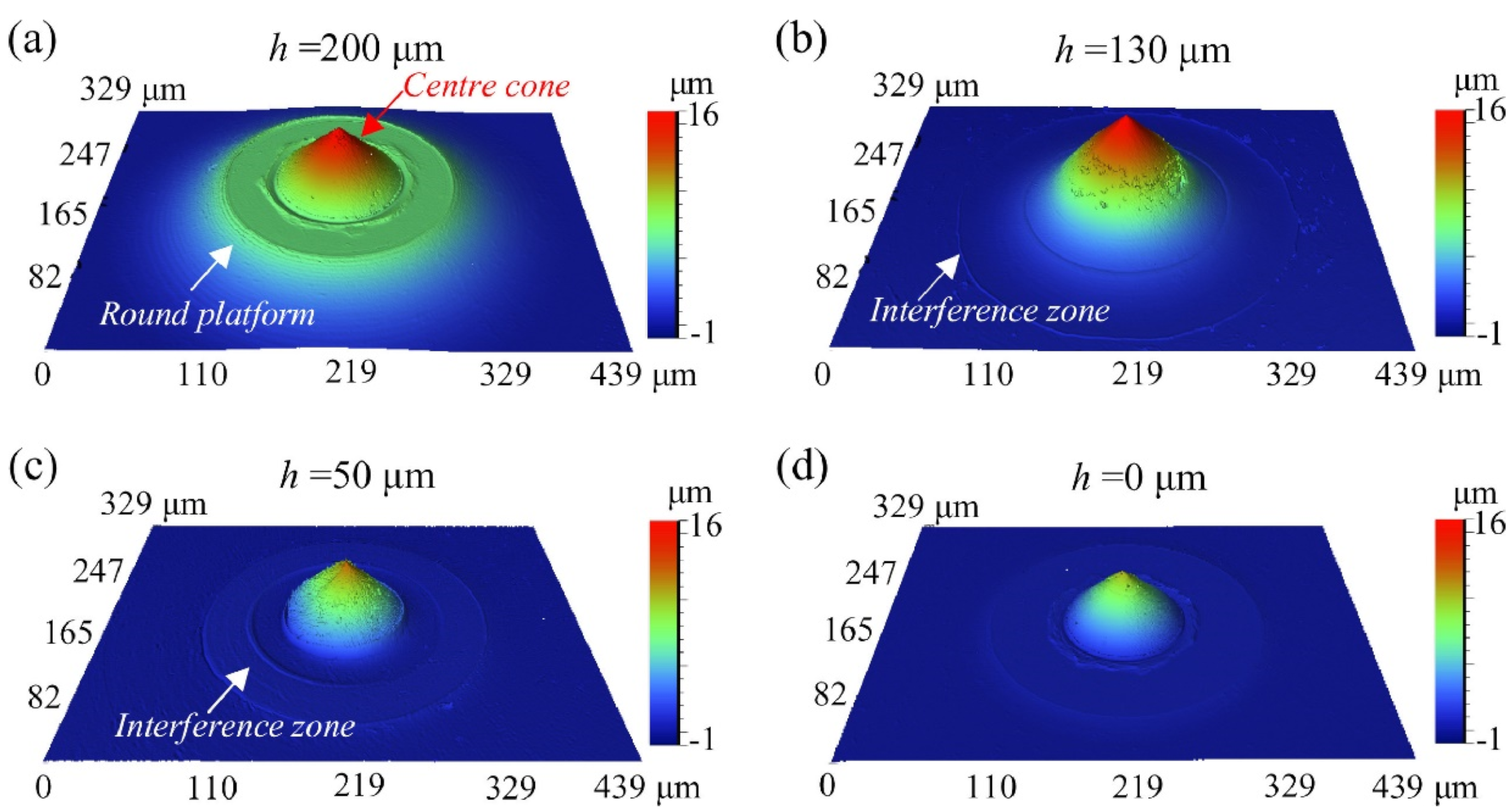
Before an online identification and compensation system for single-point diamond turning center error, the evolution of the three-dimensional shape of the center error needs to be understood. During the machining process, owing to the presence of errors between the tool and the workpiece center, the machined surface forms a three-dimensional shape similar to a cylinder or a cone; Figure 7 represents an experimental description of the evolution of the center cone, where h represents the horizontal distance between the tool and the workpiece center. When h = 200, there is no interference between the workpiece and the tool, as shown in Figure 7a; when h = 130, the tool interferes with the surface of the workpiece, forming an apparent interference circular table, as shown in Figure 7b; and when the tool continues to feed, the tool interferes with the workpiece secondarily, as shown in Figure 7c,d. However, the three-dimensional shape of this center error can also be predicted by mathematical models. He et al. [69] developed a theoretical model for the three-dimensional shape of the workpiece end face based on cutting force signals, which was effectively verified in experiments. For complex spherical surfaces or free-form surfaces, mathematical models can also be established to predict the three-dimensional shape of the machined surface of the workpiece. Huang et al. [70] developed a three-dimensional mathematical model of complex spherical surfaces or free-form surfaces using an appropriate rotational coordinate system, and this mathematical model of the machined surface could effectively identify the contour shape of the workpiece surface, which indirectly reflects the roughness of the workpiece surface. The three-dimensional shape of the center error measured by the experiment and theoretical mathematical model lays the foundation for establishing an online identification system of single-point diamond turning center error.
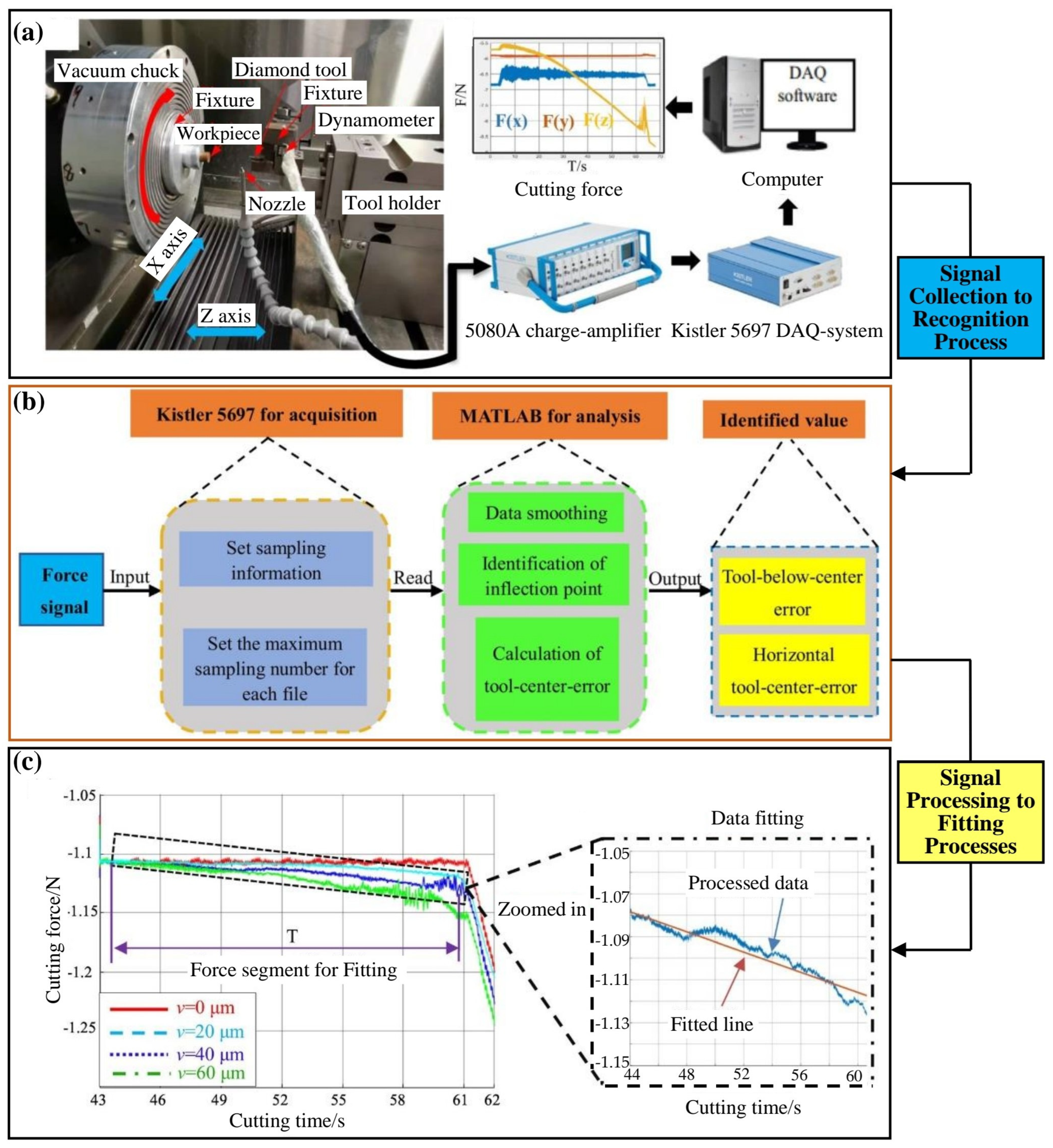
Through the three-dimensional shape evolution law of the center error, the identification model of the center error can be established based on a cutting force signal. Zhang et al. [67,72] investigated the effect of a single-point diamond turning tool with high error tool interference on the center cone of the workpiece and established a two-dimensional tool-center-error identification model based on the cutting force signal. By using this error identification model, the size of the center error can be calculated for online identification. In addition to end face center error modeling, the center error of convex spherical surfaces can also be modeled using this modeling approach. Dai et al. [19,71] investigated the effect of tool error on the shape accuracy of the convex spherical surface during single-point diamond turning, established a mathematical model of tool deviation based on the cutting force, clarified the mapping relationship between the cutting force and the tool interference zone, and also utilized the cutting force signals for online identification of tool deviation. By analyzing the effect of tool deviation on the three-dimensional morphology of the residual structure in the center of the convex spherical surface, the three-dimensional morphology of the convex spherical surface was predicted online based on the cutting force signal. By comparing the theoretical values with the experimental results, it was concluded that the established cutting force model has an accurate correspondence with the morphology of the interference zone, which can realize the online identification of the error above the tool center and significantly improve the cutting efficiency and the machining accuracy of single-point diamonds. To meet the requirements of intelligent development, an online identification system of center error needs to be developed based on the online identification model of center error. Ma et al. [26] designed an error online identification system based on error identification theory, as shown in Figure 8. According to principles of signal acquisition and data processing, they analyzed cutting forces and set up the experimental apparatus as shown in Figure 8a; subsequently, they processed and computed the cutting force signals using MATLAB 2018, as depicted in Figure 8b. Lastly, they obtained inflection points of the cutting force curve and slopes of its first half, as illustrated in Figure 8c. Through this system, tool errors could be identified, enabling subsequent compensation measures.
After the center error identification model is established, a real-time compensation system for center error needs to be established because the ultimate goal of error identification is to obtain a high-precision surface of an optical element that fits the bill, and the parameters of the tool need to be adjusted according to the results of the identification to minimize the effect of the center error on the surface of the workpiece. Displacement compensation was realized by setting up the corresponding mechanism, and this method was also verified in experiments. Daisuke et al. [73] utilized a fine-motion drive mechanism to compensate for the error of the workpiece. The method first uses the Fourier series to analyze the error obtained from the measurement; subsequently, the frequency of the error is determined according to its wavelength characteristics; and, finally, the workpiece is compensated through a fine-motion drive mechanism. The accuracy of the compensated results was experimentally found to be 60% higher than that of the uncompensated results.
Along with the development of CNC systems, error compensation is able to be accomplished by setting tool offset through the control program of the machine tool. Gu et al. [74] came up with a method of global offset compensation for the center error of machined parts by the machine tool program. This method establishes an error model in the form of a chi-square transformation matrix for the characteristic data of each part. After this, the method derives the offset parameter and, next, sets the compensation settings of the program according to the value of the offset parameter on the machine to achieve the effect of error compensation. In addition, this method has been validated in side milling experiments. Yu et al. [75] came up with a method to establish a tool error identification model and compensation method based on force signals; first of all, the comprehensive error is divided into static error and dynamic error, and an error identification model is developed. After this, the tool error is predicted according to the error model, and, finally, the CNC code is adjusted according to the prediction results to change the tool’s position point. After experimental comparisons, it was found that the compensated accuracy was improved by 35–55% compared to the original accuracy. Since the motion control of ultra-precision machine tools is also realized through the CNC system, the offset can be set in the program to complete the compensation after identifying the size of the error. For instance, Kong et al. [76] developed shape error compensation software based on the CNC system for ultra-precision machining, and the software obtains the size of the error by establishing an error identification model and, next, modifies the program offset in the machining program to alter the tool’s trajectory. Attributable to the gradual improvement of the theory of error compensation, the use of the corresponding iterative compensation method can also be realized in the CNC machine tool error compensation. Lee et al. [77] used the recursive compensation method and machine tool CNC system to compensate for the error. First, the author collects cutting force signals, analyzes and processes them by capacitive sensors and software to derive the offset value, and follows the compensation program written on the CNC system through the recursive compensation method to realize the compensation process.
Another method of center error compensation is to build a real-time compensation system based on the center error identification model; this method establishes a displacement control system by utilizing force signals and completes the compensation by controlling the feed of the tool in real time according to the offset of the tool. This indirect method of error identification and compensation has made some research progress in ultra-precision machining because of its efficiency. Wu et al. [78] established a high-precision method for identifying horizontal centrifugal errors of ultra-precision ball-end milling tools based on force signals, along with a compensation method for tool center offset errors. This method was validated on micro-spherical surfaces, micro-spherical arrays, and micro-sinusoidal surfaces, and it was found that this error identification and compensation method is able to improve the milling accuracy of the workpiece significantly. Liu et al. [79] established an error compensation system based on an error identification model on ultra-precision machined spherical surfaces using force signals; in the experimental process, the model was used to identify the machining errors that exist in the machined spherical surface. Based on the results of the identification, the next spherical surface was compensated for the errors as well as simulated and analyzed, and the experimental results demonstrated that the surface roughness after compensation was lower than that before compensation, validating the effectiveness of the model.
Considering the development requirements of manufacturing intelligence, after the above literature review, it was found that a compensation system for online identification of center error can be constructed by combining force signals, IoT, and intelligent algorithms to realize the real-time measurement of workpiece surface topography, real-time calculation of error values, and real-time adjustment of tool position parameters to reduce the impact of center error on workpiece surface quality.

3.2. Tool Wear Monitoring

Real-time and accurate monitoring and evaluation of tool wear have long been critical challenges in the manufacturing industry [80]. Diamond tools are commonly employed for cutting in ultra-precision machining. However, diamond tools are prone to severe wear when machining certain materials. For instance, during ultra-precision machining of iron-based materials, the interaction between iron and carbon atoms leads to significant wear on diamond tools, which severely impacts machining accuracy, productivity, and safety. Currently, detecting tool wear often requires specialized instruments, such as white light interferometers, making the process complex, time-consuming, and inefficient. Therefore, developing intelligent models for identifying and monitoring the wear state of diamond tools is essential.
Tool wear monitoring methods are classified into direct and indirect approaches [81]. Direct methods, such as offline or in situ inspection of the cutting edge using optical inspection techniques, may interrupt the smooth flow of the machining process and impact the quality of the machined surface; the indirect method is to collect and analyze the signals generated during the cutting process, such as cutting force signals [82], acceleration signals [83], and acoustic emission signals [84,85], to indirectly determined whether the cutting edge of the diamond tool is worn or not. However, in the process of ultra-precision machining, the wear of diamond tools is generally a trace amount of wear. Conventional inspection techniques cannot complete the detection, and compared to direct methods, indirect methods offer greater efficiency and accuracy. Therefore, online monitoring of diamond tool wear can be realized indirectly.
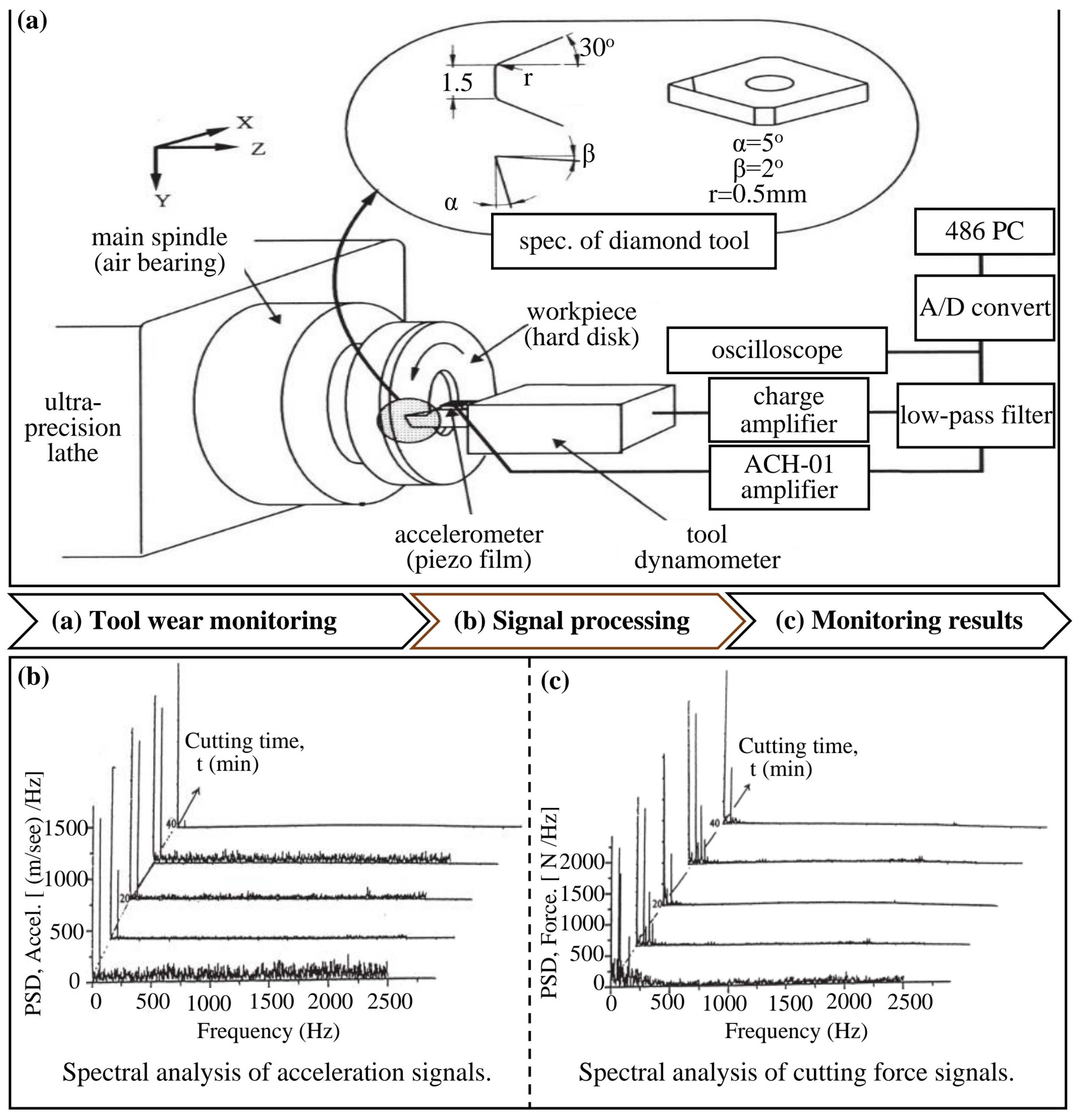
The indirect method uses force signals, acceleration signals, and acoustic emission signals as a medium to construct a tool wear monitoring system, and among them, cutting force signals are the most widely used. Choi and Kim [86] developed an online monitoring system for diamond tool wear by acquiring cutting force signals and acceleration signals for multi-frequency response analysis. By analyzing the frequency response of the two cutting force signals, it was possible to distinguish between the wear state and the normal state of the tool, and during ultra-precision machining, the system could monitor tool wear in real time and adjust the positions of tools and workpieces to ensure machining quality. The schematic of the monitoring system is illustrated in Figure 9. The authors utilized accelerometers to collect signals, which were subsequently processed through charge methods, filtering, and A/D conversion before being analyzed on a computer, as depicted in Figure 9a. Post data input, secondary processing was conducted, as shown in Figure 9b, and utilizing this system, they observed effective monitoring of tool wear, as demonstrated in Figure 9c. Since the cutting force signals generated during the cutting process are susceptible to environmental disturbances, tool wear monitoring can be performed using dynamic modeling. Ko et al. [87] used dynamic cutting force signals for online monitoring of diamond tool wear conditions; in the identification process, the authors used a fuzzy algorithm for AR modeling of the collected data to identify the wear state of the tool based on time series analysis to prevent the diamond tool from cutting edge from extensive damage, which affects the machining quality. Since acoustic emission signals are more sensitive than force signals and less prone to environmental interference, making them suitable for modeling tool wear monitoring, Jose et al. [88] utilized acoustic emission signals to conduct online monitoring and analysis of tool wear and surface roughness during turning. Their experiments revealed that increased cutting noise corresponds to higher cutting forces and more severe tool wear, indicating that the indirect method is effective for monitoring tool wear.
In recent years, with the rise of artificial intelligence, the indirect method of tool wear monitoring has begun to develop towards intelligence, mainly using intelligent algorithms combined with cutting signals to realize tool wear monitoring; with this approach to intelligent monitoring, some algorithmic structures have emerged that are suitable for tool wear monitoring, in which the use of artificial neural network algorithms [89] and deep learning algorithms structure [90] to build a tool wear intelligent monitoring system model is the most prevalent. Its structure is shown in Figure 10. For neural network algorithm structures, utilizing foundational signals to construct training models can yield highly accurate predictions of tool wear, as depicted in Figure 10a; similarly, deep learning algorithm structures require establishing training models for feature extraction to determine the tool’s wear state, as shown in Figure 10b.
The two algorithmic structures shown above are mainly used in the signal processing of tool wear monitoring; the better the signal processing, the higher the accuracy of tool wear monitoring. When the signal processing adopts a neural network structure, neural networks can realize arbitrary nonlinear mapping using parallel distributed information processing and process a large number of information inputs simultaneously; therefore, neural networks can be utilized to construct a signal processing model. Wang et al. [93] developed an auto-associative neural network (AANN) algorithm to monitor tool wear state online under milling conditions. They collected wear signals, extracted feature values, and inputted them into the system model, and the final output value indicates tool wear severity. Sick [94] utilized a neural network for online detection of tool wear state during turning by using a multilayer sensing system to collect tool cutting signals and fuse them with a neural network; in this process, the authors proposed a novel signal processing method to establish the mathematical relationship between tool wear parameters and wear signals, facilitating online monitoring of tool wear. Therefore, sound signal processing can be obtained by using a neural network structure.
However, to achieve more effective signal processing, the neural network would need to be enhanced with a BP algorithm; this algorithm can be iterated over and over to achieve a predetermined goal, thus improving signal processing, and has been validated in many experiments. Choudhury et al. [95] developed a tool wear monitoring system using a photoelectric sensor system combined with a multilayer neural network algorithm. The system first uses the BP algorithm to train the algorithm on the data obtained from multiple experimental collections, and, after this, the system collects cutting force signals during the machining process through the use of a sensor system. Next, the system converts them into digital signals for input into the algorithm through the A/D converter to establish a mathematical relationship between the amount of tool cutting edge wear and the dimensions of the machined workpiece and to realize the prediction of the tool’s wear. Ezugwu et al. [96] developed a neural network monitoring model for the online prediction of tool wear based on a BP algorithm; the authors first built an empirical database based on preliminary experiments and, next, characterized the cutting data and input it into the model to obtain the corresponding tool wear prediction. In addition, the fuzzy neural network proposed by Kuo et al. [97] can also be applied to the process of signal processing; the authors developed a multi-sensor-integrated system by combining neural networks and fuzzy logic algorithms to realize the online tool wear monitoring process. The monitoring process consists of five parts: data collection, feature extraction, pattern recognition, multi-sensor integration, and tool distance compensation. The multi-sensor system collects and extracts the force, vibration, and acoustic emission signals of the cutting process, characterizes them, and transmits the feature values into the neural network system to realize the accurate prediction of tool wear. Therefore, neural networks can be used for tool wear monitoring, and good monitoring results can be obtained.
From the above overview, it can be found that tool wear monitoring can be realized by neural networks, which is a kind of deep learning, and it can be inferred that deep learning algorithms can also be applied to the tool wear monitoring process. Deep learning algorithms are also mainly applied to tool wear signal processing, which is applied on the same principle as neural networks. Figure 11 shows the results of tool wear prediction using deep learning models by He et al. [98]. The authors input the temperature signal into the trained deep learning model to obtain the prediction of tool wear, and the monitoring result graph is shown in Figure 11. In Figure 11a, when the tool wear value is less than 200 µm, the predicted value is higher than the measured value, with a small error; when the tool wear value is greater than 200 µm, the measured value is higher than the predicted value, with a larger error. In Figure 11b, when the tool wear value is less than 200 µm, the predicted value is higher than the measured value, with a larger error; when the tool wear value is greater than 200 µm, the measured value is higher than the predicted value, with a smaller error. In Figure 11c, when the tool wear value is less than 500 µm, the predicted value is higher than the measured value, and the error first increases and then decreases; when the tool wear value is greater than 500 µm, the measured value is higher than the predicted value, with a larger error. In Figure 11d, when the tool wear value is less than 450 µm, the predicted value is higher than the measured value, and the error gradually decreases; when the tool wear value is greater than 450 µm, the measured value is higher than the predicted value, and the error gradually increases. In Figure 11e, the predicted value curve closely matches the measured value curve, with a small error. Therefore, the prediction results corresponding to Test 5 in Figure 11e are the most accurate. These results indicate that signal processing can also be performed accurately and efficiently using the deep learning algorithm models. Cao and Zhen [99] designed a multi-sensor tool wear monitoring system based on spatiotemporal feature recognition based on traditional deep learning algorithms. The system uses multi-sensors to collect signals and process them, extracts the spatial features of the signals by using a convolutional neural network, extracts the temporal features by using a bi-directional long-short time memory network, and finally analyzes and summarizes them. Through simulation experiments, it can be obtained that the recognition process of this monitoring system is simple, the recognition accuracy is high, and the applicability is strong. Zhu et al. [100] used a deep learning approach to realize the wear monitoring of the tool, firstly integrating the physical information into the data-driven model, which trains the algorithmic model; subsequently completing the wear monitoring of the tool based on the cutting force signals; and, finally, verifying the model’s versatility and accuracy under different conditions. Gouarir et al. [101] investigated a technique for tool wear monitoring using deep learning, which uses an empirical database including data from previous machining examples to build a convolutional neural network by incorporating a self-learning and adaptive control system to enable the prediction of tool wear. Manivannan et al. [102] presented a tool wear monitoring system built using sensor signals, such as acoustic emission/cutting force, a data acquisition monitoring system, and different decision-making algorithms. Therefore, deep learning algorithms can also be applied to the tool wear monitoring process, and good monitoring results have also been achieved.
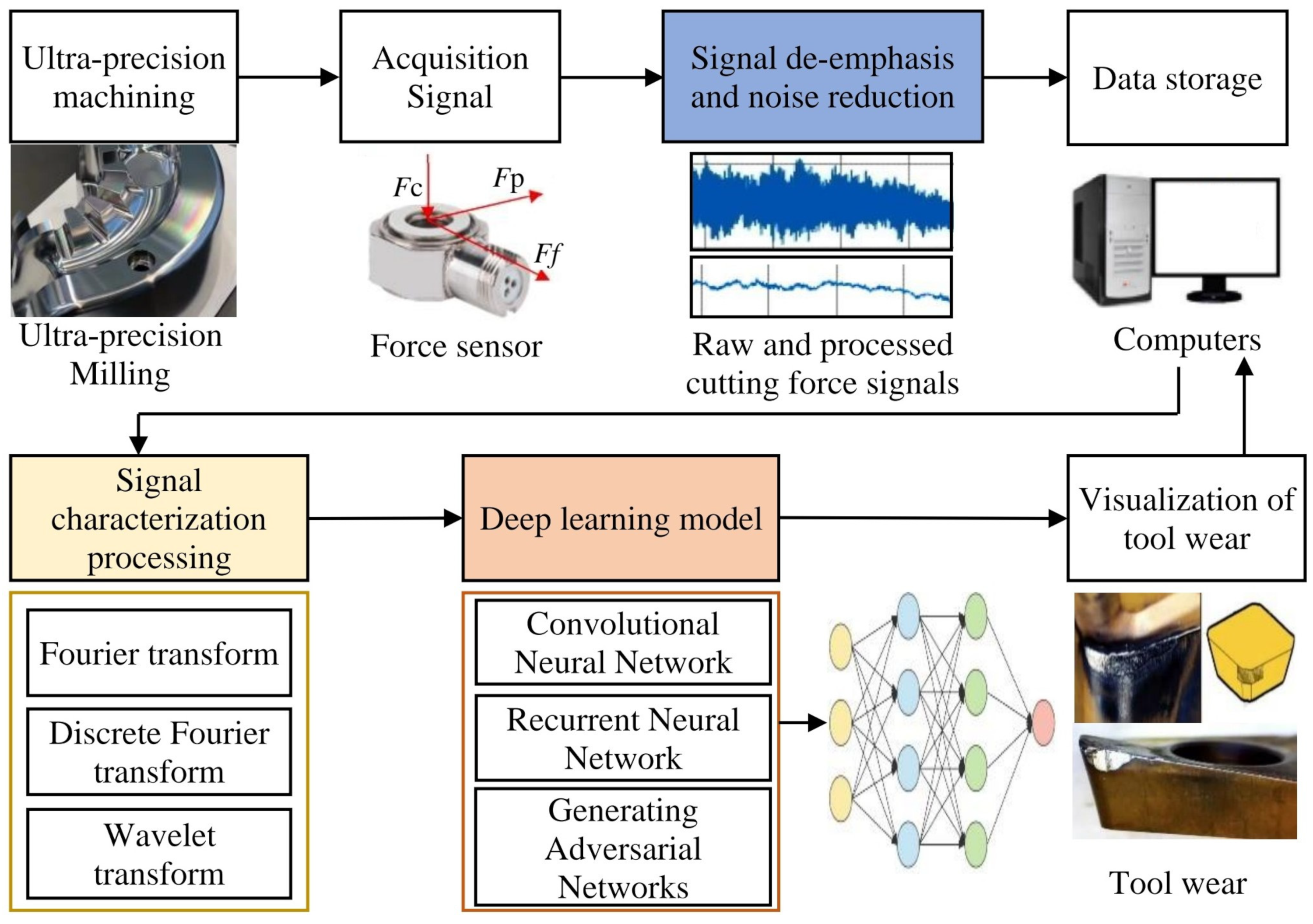
Indirect methods for tool wear monitoring are beginning to be refined as the algorithmic structures become more and more effective in processing. This paper summarizes a framework for intelligent monitoring of diamond tool wear based on indirect monitoring, as shown in Figure 12; considering the complexity, accuracy, and acquisition cost of the intelligent monitoring system, the architecture of the tool wear intelligent monitoring system shown in Figure 12 is built based on force signals. In Figure 12, the force signal generated during machining is first acquired using a force sensor since the collected signal has a large presence of impurities, such as noise, which affects the magnitude of the eigenvalues during the characterization process. It is necessary to use filters for deblurring and noise reduction, and, after this, the signal is stored in a computer; the signal is characterized to obtain the eigenvalues, which are subsequently fed into a deep learning algorithm system to obtain the visualized tool wear state finally.

3.3. Dynamic Balance Adjustment

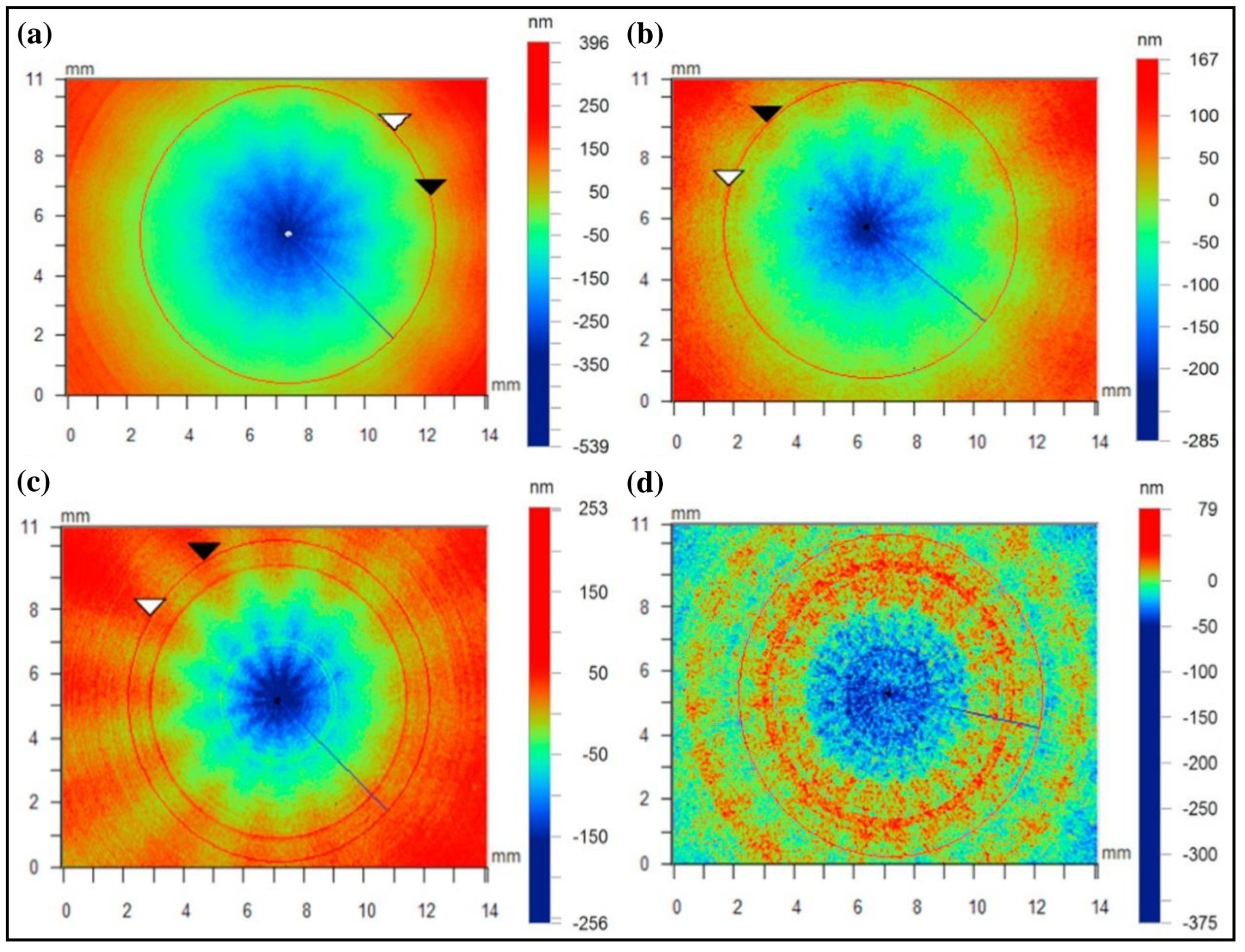
Dynamic balance adjustment is the primary means of solving spindle system imbalance faults and reducing spindle vibration [103]; this is because the presence of clamping eccentricity in the workpiece during clamping usually leads to changes in the dynamic balance of the spindle. It has been found that the shift in dynamic balance can seriously affect the machining accuracy of the workpiece. Wu et al. [104] examined the effects of spindle axial drift on the workpiece surface during ultra-precision turning, verified the issue of spindle axial drift during machining, developed a mechanical model of the spindle system considering quality eccentricity, and analyzed how spindle speed and dynamic balance influence the surface topography of the workpiece, and the experimental results are shown in Figure 13. In Figure 13a, when a 1 g mass is applied to the spindle at a speed of 1000 r/min, and the analysis is performed at a radius of 5 mm, 13 distinct petal-shaped ripples appear on the workpiece surface. The outer height of the workpiece reaches 396 nm, while the inner height is −539 nm, showing a higher outer and lower inner surface morphology. In Figure 13b, when a 1 g mass is applied to the spindle at 1200 r/min, and the analysis is performed at a radius of 5 mm, 13 distinct petal-shaped ripples are also observed, but the outer height of the workpiece reduces to 167 nm, and the inner height is −285 nm. In Figure 13c, when a 1 g mass is removed from the spindle at 1000 r/min, and the analysis is performed at a radius of 5 mm, 13 distinct petal-shaped ripples remain, with the outer height reaching 253 nm and the inner height −256 nm, but the morphology of the workpiece shows no significant fluctuation. In Figure 13d, when a 1 g mass is removed from the spindle at 1000 r/min, and the analysis is performed at a radius of 5 mm, the petal-shaped ripples disappear, with the outer height reducing to 79 nm and the inner height being −375 nm. The surface morphology of the workpiece gradually improves. Therefore, the spindle dynamic balance needs to be adjusted before machining.
The methods of dynamic balance adjustment are direct and indirect. The direct method is mainly to adjust the mass distribution on the spindle by adjusting the loose bolts on the spindle through human operation to make the mass on the spindle as evenly distributed as possible. This method is cumbersome and not easy to control; therefore, it does not meet the requirements of the development of intelligent machine tools. The indirect method is to use the corresponding media to establish the algorithm model through the input signal and directly on the machine tool spindle adjustment until meeting the processing requirements. This method is convenient and efficient and can be applied to most of the ultra-precision machining processes. Therefore, this paper reviews spindle dynamic balance online monitoring technology; spindle dynamic balance online adjustment technology usually uses an algorithmic system to collect the positional parameters of the spindle, which mainly collects the vibration signal of the spindle [105]; after that, the filtering method is used for signal processing and analysis, and the mathematical equation is established according to the least squares fitting method to derive the rotational curve of the spindle dynamic balancing. Finally, the machine control system is used to adjust the position of large eccentricity between the spindle and the workpiece, ensuring machining accuracy and machining efficiency.
For the research of spindle dynamic balance online adjustment technology, the influence coefficient method [29,30] and modal balance method [28,31] appeared according to the mechanical dynamic balance theory. The influence coefficient method is the relationship between the mass matrix, stiffness matrix, and force matrix, which indirectly reflects the magnitude of the dynamic balance, which plays an important role in the regulation of the dynamic balance of the spindle. This has been verified in the experiment of Zhu et al. [106], who investigated the dynamic balance adjustment of spindles using the influence coefficient method. The authors collected the spindle vibration signals to obtain the corresponding amplitude and phase, calculated the vibration coefficient and the size of the balancing component and other parameters, and, next, corrected the mass weights of the objects on the spindle to obtain the appropriate dynamic balancing data. The modal equilibrium method is a method of determining the response of a structure when subjected to external forces by analyzing the vibration modes of the structure. This method allows the response of a structure to be analyzed quickly and accurately, and adjustments can be made quickly. This method can also be used in the study of dynamic balancing adjustment of spindles for ultra-precision machine tools, and relevant experiments have been carried out. Sadeghipour et al. [107], based on the modal balancing method, achieved dynamic balancing by inserting a mass into the rotor system, thus reducing the effect of vibration and improving the dynamic performance of the system. Based on these studies, many on-site dynamic balancing testing instruments have been developed, among which the multi-cylinder dynamic balancing tester [108] is the most widely used, which collects vibration signals through the use of acceleration sensors, obtains the amplitude and phase of vibration signals through the corresponding signal processing methods, and indirectly outputs the unbalanced position points. Although the dynamic balancing tester has high testing accuracy, it has low adjustment efficiency and a complicated adjustment process; therefore, it is not suitable for the intelligent testing process. Thus, the spindle dynamic balancing adjustment process requires the development of online adjustment technology.
Online dynamic balance adjustment occurs mainly through the development of algorithmic systems or signal data recognition methods, such as vibration signal acquisition and processing, to obtain the corresponding dynamic imbalance position data. Subsequently, the rotor system on the quality of reasonable adjustment, based on this monitoring process and using a position data collector to collect the position data of the spindle calibration point in real time, can complete the process of monitoring the dynamic balance of the spindle. Zhang et al. [109] developed an online dynamic balance adjustment technology for CNC machine tool spindles, utilizing a real-time position data acquisition controller. This method eliminates the need for external sensors by relying on the machine tool’s position controller to collect spindle position signals; it employs least squares fitting, adaptive harmonic wavelet filtering, mutual correlation extraction, and single-plane influence coefficient methods to extract the amplitude, phase, and frequency of the signals. The technology then calculates the calibration mass and position for dynamic balance, enabling real-time measurement and calibration of spindle dynamic balance. Liu et al. [110] utilized the real-time data module of a machine numerical control system and disturbance observer in combination to realize the spindle dynamic balance online prediction and adjustment. They used the test data of open-loop identification and the servo control system of the machine’s high precision and high performance. They used the recursive least squares method to establish the high-precision prediction model of the spindle dynamic balance; the predicted accuracy of dynamic balancing and the machining accuracy after adjustment were effectively verified in the experiment. Figure 14 demonstrates the effect of spindle error on the workpiece surface at various spindle speeds. In Figure 14a, when the spindle speed is set to 40,000 rpm, 20 distinct grinding marks appear on the workpiece surface, with the maximum scratch height reaching 1.854 µm. In Figure 14b, when the spindle speed is increased to 40,200 rpm, no significant scratches are observed on the workpiece surface, which remains relatively smooth. The maximum height on the surface is 0.978 µm, with the lowest depth at −0.993 µm. In Figure 14c, when the spindle speed is increased to 40,400 rpm, noticeable grinding marks are observed on the workpiece surface, though they are smaller in size, and a distinct circular bulge appears on the surface. The maximum height is 0.593 µm, and the minimum depth is −0.623 µm. In Figure 14d, when the spindle speed is increased to 41,000 rpm, noticeable grinding marks remain on the workpiece surface, with small scratch sizes. The minimum depth of the surface reaches −0.844 µm, and the maximum depth is −0.858 µm, with the entire surface taking on a groove-like shape. However, the method described above is not very accurate in adjusting the dynamic balance of the spindle.
To be able to improve the accuracy of spindle dynamic balance monitoring, some scholars thought that the spindle vibration signal could be used to establish a dynamic balance identification model to realize the online monitoring of dynamic balance. Through continuous research, this method has made good progress experimentally. Wang et al. [112] developed an online monitoring method for spindle dynamic balance. The method chiefly presses the use of sensors to collect the vibration signals of the spindle; next, adopts the Fourier transform, polynomial curve fitting, and Hooke’s law method of spectral analysis and uses the LabVIEW 2017 software to program and process the obtained signals; and, finally, transmits the output signals to the dynamic balancing device according to the output signals to realize the online monitoring and adjustment of the dynamic balancing of the spindle. Zhang et al. [113] developed an online adjustment technology for spindle dynamic balance based on the double-sided influence coefficient method. This technology employs an embedded dynamic balance device featuring a signal acquisition system, an analysis and control system, and a hydraulic system for processing signals; it allows for the adjustment of the spindle system’s imbalance vector without machine stoppage, effectively reducing system imbalance vibrations.
In addition, considering the accuracy of the vibration signal processing and analysis process, some scholars have found that an algorithmic system based on the force signal recognition model can be used for signal processing, which can effectively improve the accuracy of recognition. Wang et al. [21] used particle swarm optimization to study the dynamic balance of the spindle rotor system through the development of algorithms to achieve the suppression of nonlinear vibration at high speeds of the spindle as well as the adjustment of the dynamic balance of the rotor system. Liu et al. [114] introduced a fuzzy self-tuning single-neuron PID control method for dynamic balancing of rotor systems based on fuzzy control theory and neural networks. This approach first acquires vibration signals using sensors, compares the vibration amplitude to a predefined target, and sends the difference to a fuzzy controller; the fuzzy controller then determines the gain K function for a single neuron and the control step size; this method effectively manages rotor imbalance and has been experimentally validated to exhibit strong robustness and excellent stability. Yun et al. [115] introduced a novel method for detecting and adjusting spindle dynamic balance based on the identification of energy transfer coefficients; the method calculates the value and phase of the spindle unbalance vector by extracting the vibration signal of the spindle system, establishes a mathematical model, and corrects it using the frequency response function correction method to realize online adjustment of the rotor’s equilibrium state to improve the balancing efficiency. The spindle dynamic balancing adjustment method summarized above can effectively realize the spindle to achieve a balanced state.
The spindle dynamic balance adjustment methods outlined above are all designed to enable the spindle to achieve the ideal balance state; among the many methods of dynamic balance compensation, the spindle dynamic balance can be effectively adjusted by the gain parameter adaptive method. Zhang et al. [116] developed an online dynamic balancing technique for high-speed spindles, combining gain parameter adaptation and scheduling control methods, proving that adaptive gain scheduling improves balancing accuracy. Moreover, improving the influence coefficient method to establish the dynamic balance adjustment model can also realize spindle dynamic balance online adjustment. Pian et al. [117] analyzed the calculation method of dynamic balance in machinery, proposed the compensation method for imbalance as well as the theory of automatic compensation, and improved the dynamic balance adjustment method based on the theory of influence coefficient method, and Fan et al. [118] proposed a frequency domain adaptive balancing algorithm for electric spindles based on a modified estimation model of influence coefficients. The method collects vibration signals, filters them, extracts frequency components, and transforms them into frequency domain signals. This method ensures precise spindle balancing. In addition, online dynamic balance adjustment of the spindle can also be realized by a genetic algorithm. Wang et al. [119] proposed a genetic algorithm-based online dynamic balance compensation method, controlling mass distribution, balancing unbalanced force, and reducing spindle vibration amplitude. To optimize the layout of the monitoring system and simplify the size of the monitoring system, the spindle dynamic balancing identification process and the adjustment process should be inherited in one. Zhang et al. [120] developed a high-speed machine spindle double-sided online dynamic balancing adjustment device and control system. The device collects vibration signals, accurately separates unbalanced components, and fits them using a least squares algorithm, and the computer analyzes spindle vibration conditions, calculates correction vectors, and outputs control signals. Therefore, the above-described method of adjusting the dynamic balance of the spindle can effectively balance the condition of the spindle.
Through the analysis of the spindle dynamic balance adjustment methods, it can be found that the traditional inspection methods are not well realized in the dynamic balance inspection process of the spindle of ultra-precision machine tools owing to the shortcomings of deviation from linearity, low efficiency, and low inspection accuracy. However, based on the algorithmic system or the theory of automatic control, the spindle dynamic balance can be realized for online detection and adjustment, and its detection and adjustment effect is good. In this online detection and adjustment process, the vibration signals of the spindle system can be collected first, subsequently processed and analyzed by the corresponding algorithms, and finally input into the corresponding algorithm system to realize the real-time control of the dynamic balance adjustment process. This method effectively avoids the shortcomings of traditional detection methods, but its stability still needs further research because it is easily disturbed by external factors.

3.4. Tool Setting

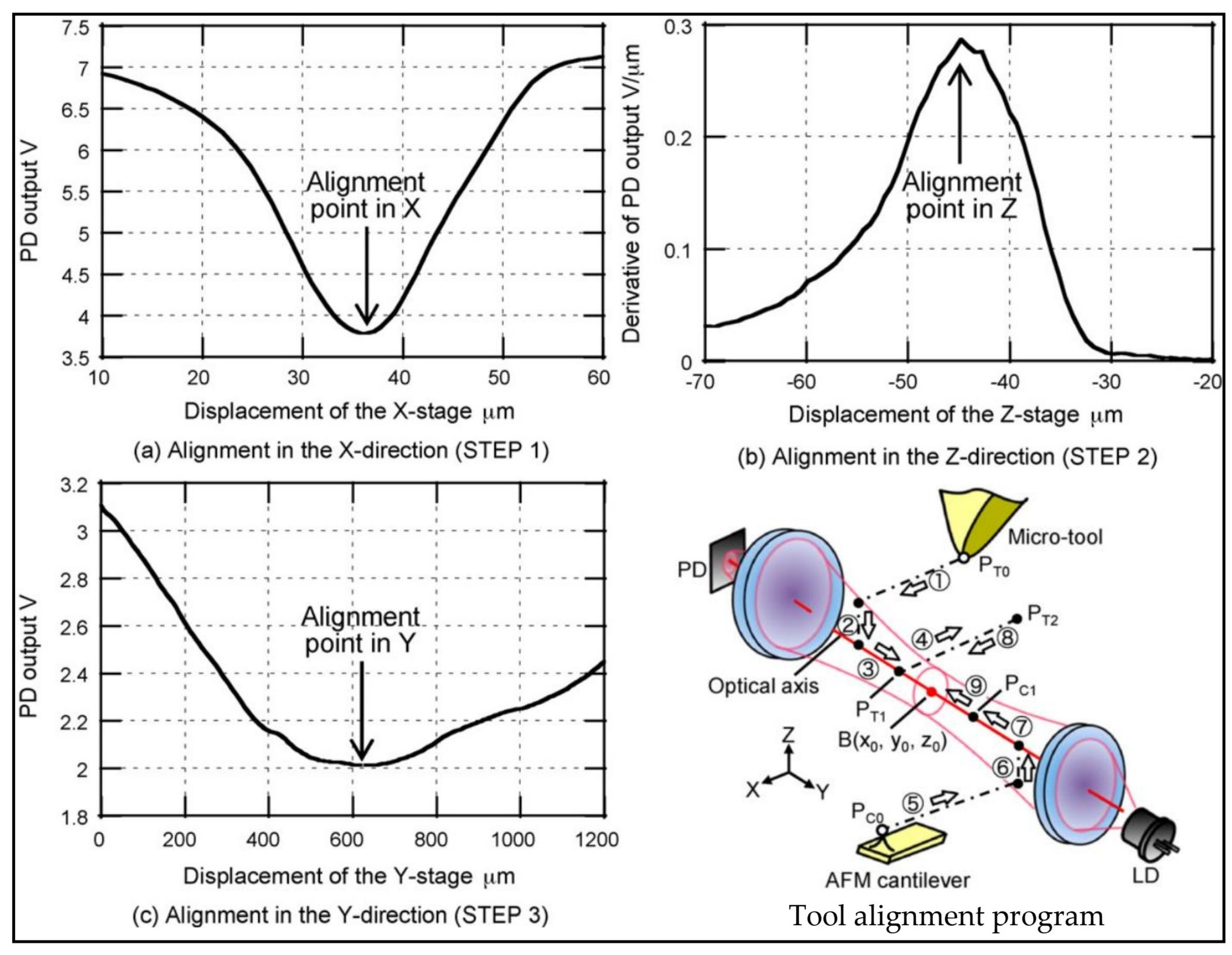
In the process of ultra-precision machining, the tool-setting error directly affects the workpiece’s surface morphology, which severely impacts machining accuracy [121,122,123]. To ensure the accuracy requirements of ultra-precision machining, human operation is usually used in the tool-setting process; this method of tool setting could be more efficient and easier to control in terms of accuracy. However, with the rapid development of optical microscopy, it has been found that fast and accurate tool alignment can be achieved using optical instruments, resulting in high efficiency and easy control over tool alignment accuracy. Figure 15 shows the experimental results of tool setting using an optical instrument in the X, Y, and Z directions of the tool, from which optical instruments can realize the alignment of the cutting edge of the micro-tool. However, this method of tool alignment still requires manual installation and disassembly of the tool alignment apparatus, which does not meet the requirements of intelligent development. Therefore, there is a need to develop intelligent tool-setting technology to help achieve high accuracy and efficiency in the ultra-precision machining process.
As machining accuracy continues to improve, intelligent tool setting has been a hot research topic; in traditional machining, the automatic tool-setting method first appeared in the grinding process, such as in the non-contact automatic tool-setting process used for internal thread grinding [125]. Subsequently, the emergence of sensors has driven the application of cutting signals in intelligent tool-setting processes; for instance, the use of acoustic emission signals can monitor the contact position between the tool and the workpiece, facilitating the widespread application of acoustic emission signal monitoring in grinding wheel positioning during grinding processes [126], and in machining processes, acoustic emission signals can be used to accurately measure tool length and determine the tool’s working coordinates [127]. Therefore, tool-setting models established using cutting signals represent another form of non-contact tool-setting method.
Although cutting signals can serve as a medium for intelligent tool setting, there are many other methods available for completing the tool-setting process, e.g., the method developed using optical media can be better applied in the intelligent tool-setting process, and among them, non-contact automatic tool settings can be realized by the laser system. Lee et al. [128] developed a non-contact automatic tool-setting method and operating software based on a laser system, which is based on the principle that when the tool moves to the mask, the laser source will be masked, and the receiver will send a signal to the CNC numerical control system through the interface device. The controller will stop the movement of the tool when it receives the signal and will store the current position of the tool in the system. It will then calculate the length and radius of the tool, compare the current tool position data with the position data set by the system to derive the amount of compensation required, and finally move the tool position again until it meets the setting requirements. In ultra-precision machining, tool setting can be achieved using the machine’s encoder control system.
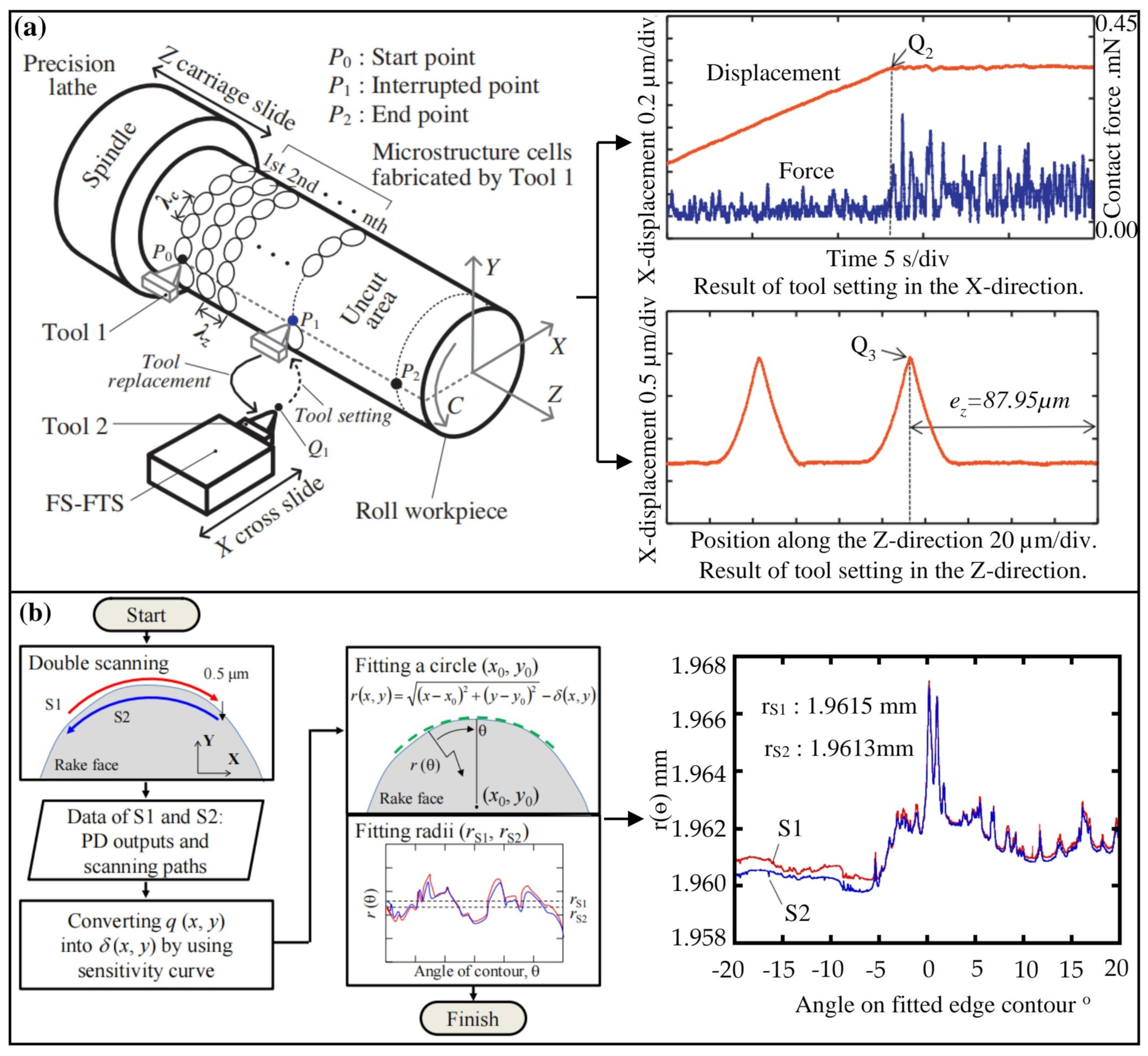
Liu et al. [129] developed a tool-setting method for free-form optical fabrication based on a fast tool servo system; this method enables fast tool setting by using a fast tool servo system that can determine the positional coordinates of the tool center and adjust the position of the tool according to the distance between the tool and the workpiece. Subsequently, the rapid development of sensors drove the application of the tool-setting process in machine tools. Gao et al. [130] improved and proposed a method for tool alignment during tool change based on sensor integration; the method utilizes force sensors to capture the constant contact force of a fast tool servo control for the machining process and detects the cross-sectional profile of a small reference area being machined by the old tool by scanning the tip of the new tool. Figure 16a shows a tool-setting system for microstructure arrays, where the operator sets the new tool precisely according to the defined position of the tooltip in the reference area and realizes tool setting after the tool change. Wei et al. [131] also utilized tool path planning software to identify and compensate for tool-setting errors after obtaining the tool radius and current position data. Although the methods mentioned above can be used for non-contact automatic tool-setting processes, they still cannot fully meet the requirements for intelligence; this situation persisted for decades until the emergence of intelligent algorithms gradually began to change it.
The emergence of intelligent algorithms has changed the research direction of non-contact automatic tool settings, especially the use of edge detection algorithms, which can be well realized to set the edge position of the tool as well as to adjust it; Figure 16b represents the edge detection algorithm developed based on optical probe detection, in which the algorithm calculation process is used to derive the sensitivity curve by data fitting, deduce the fitting equation, and calculate the radius of the tool as well as the machining position point. The use of the edge detection algorithm for the tool-setting process has been verified experimentally. Liu et al. [132] developed a non-contact automatic tool-setting system to determine the position of the tool using edge search and detection algorithms. The system detects the position of the tool by using a fiber optic sensor to measure the change in the time intensity of the tool as it passes through the emitted beam. Lu et al. [133] proposed an improved tool-setting method using edge detection technology, utilizing a programmable multi-axis controller (PMAC) handwheel for precise tool edge radius calculation, preventing tool-setting errors. In addition, by combining the algorithmic system with the vision system, the tool alignment point can be recognized more accurately. Chao et al. [134] developed a non-contact precision tool-setting system using edge detection, image processing, and sub-pixel segmentation techniques, enhancing the accuracy of tool setting. Additionally, automatic tool measurement can be realized based on machine vision. Liu et al. [135] developed an automatic tool-setting measurement system using machine vision, LabVIEW software for calibration, image acquisition, processing, and edge detection, optimizing tool coordinate points using Hough transform. Therefore, through the comprehensive analysis presented earlier, the emergence of intelligent algorithms has provided the possibility for the intelligence of the tool-setting process.
Figure 16. Algorithm for tool setting and cutting edge arc calculation. (a) Precision tool setup and experimental results for fabricating microstructure arrays [130]. Reproduced with permission from author, CIRP Annals—Manufacturing Technology, Elsevier, 2013. (b) Algorithm for cutting edge arc calculation and experimental results [136]. Reproduced with permission from author, Journal of Advanced Mechanical Design, Systems, and Manufacturing, JSTAGE, 2014.
Processes 12 02754 g016
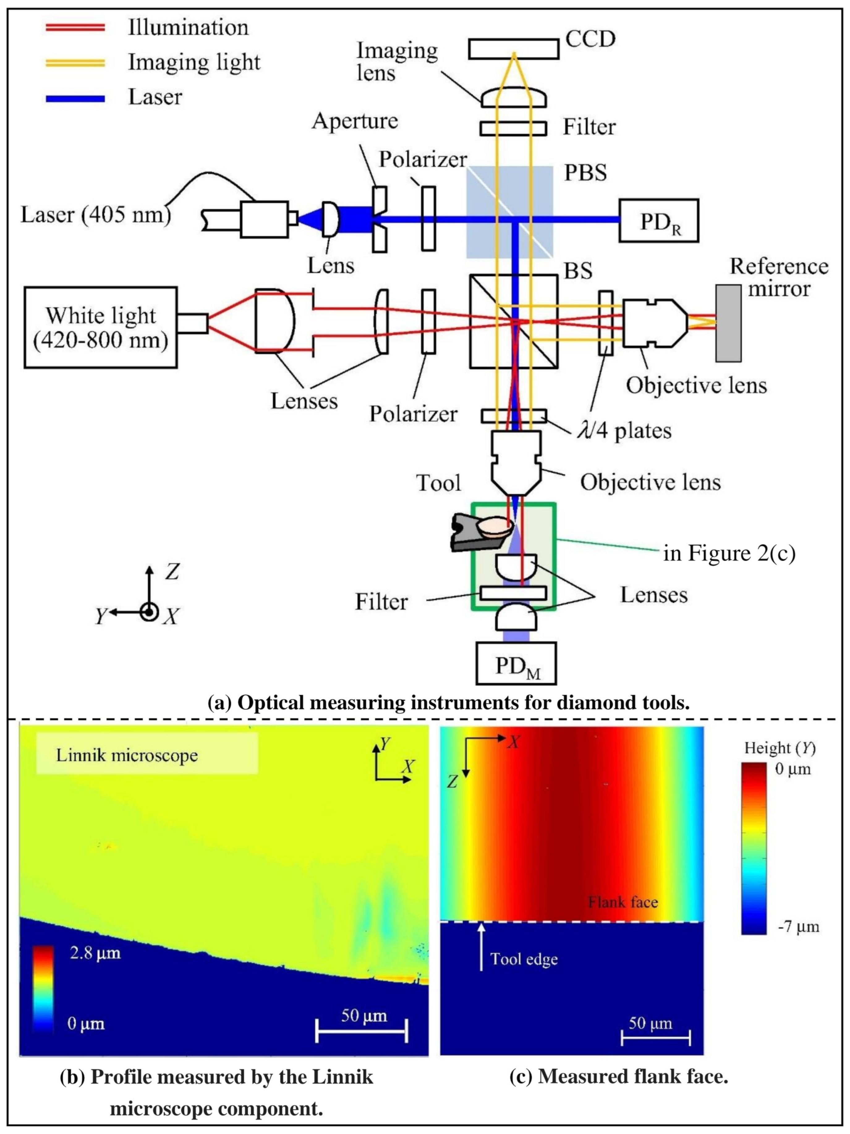
Based on the above description, it is evident that intelligent algorithms form the foundation for achieving intelligent tool-setting processes. Therefore, image processing devices and machine vision technologies developed based on intelligent algorithms can quickly and accurately obtain the machining point position of the tool and the tool radius; considering the requirements of intelligent development, this method can be applied to ultra-precision machining. Kibe et al. [137] utilized a CCD camera and machine vision software to measure the position of the tool. In this method, a CCD camera captures the image of the cutting edge of the tool; next, the image is processed using machine vision software, and the positional coordinates of the tool are obtained. Doiron [138] developed an intelligent tool-setting and measurement system using a machine vision system; the system accurately recognizes tool position and geometry, provides information to the CNC machine control system, and verifies its accuracy through experimental data comparison. Zhao et al. [139] put forward an automatic tool-setting method for precision micro-milling machining, using a microscope and CCD camera to capture images, software for image processing, calibration formula, and machine motion control; this emerging tool-setting equipment should be widely used in ultra-precision machining. Shimizu et al. [140] developed an optical measuring instrument for the multidimensional measurement of diamond tools; the instrument focuses a laser beam to scan along the tool edge, optimizes the spot diameter, and accurately measures the deviation of the tool edge profile from the scanning path of the laser beam. Figure 17 shows the structure of the tool optical measuring instrument designed by the authors. In this structure, the authors utilize a CCD camera to capture images of the tool for profiling, and edge detection algorithms are employed to calculate the tool radius and calibrate tool position points, as illustrated in Figure 17a. Experimental results provide tool edge profiles and side views, as depicted in Figure 17b. Moreover, Bono et al. [141,142] investigated the uncertainty problem of three different tool-setting methods: contact probe, machining groove, and optical tool setting. Through the establishment of mathematical models and experimental analysis, the corresponding tool-setting method uncertainty–accurate prediction model could be obtained, and this prediction process eliminated the need for repeated tool-setting setup, effectively avoiding the impact of tool-setting errors on the machining process. Therefore, integrating intelligent algorithms into optical instruments to achieve the tool-setting process is widely used in ultra-precision machining processes. This method can achieve higher tool-setting accuracy, but it still needs to meet the requirements for full intelligence. Therefore, future exploration of intelligent tool-setting processes is required.
Research into intelligent tool-setting technology reveals that tool-setting techniques developed based on traditional or emerging technologies are already widely applied across various machining processes; however, intelligent optical tool-setting technology is undoubtedly an adequate guarantee of ultra-precision machining accuracy control. This method uses optical detection technology and intelligent algorithms, and the machine body’s digital control system can be realized before machining accurate tool settings. This process operates without the need for direct contact and utilizes optical instruments to capture images of the cutting edge, subsequently marking the center of the blade and transmitting to the algorithmic system to calculate the radius of the blade. According to the marked system coordinates, by moving through the numerical control system on the tool until the tool coordinates and the system coordinates overlap to complete the process of tool setting, this tool-setting procedure is assembled into the machine system, and by developing the appropriate operating software, the tool-setting process can be completed online, whether it is the tool change process or the loading and unloading of the workpiece. Although the tool-setting error may not be eliminated, the algorithmic system control can help minimize human intervention, effectively reducing tool-setting errors and enhancing the efficiency of the tool-setting process. In addition, intelligent optical tool-setting technology can also be applied to other machining processes or the development of different control systems, providing the basis for constructing intelligent systems for ultra-precision processes.

3.5. Assisted Machining

Poor machinability of materials increases the difficulty of ultra-precision machining, potentially exacerbating tool wear, instability in cutting forces, and enlarging the thermal influence zone, thereby reducing machining accuracy and surface quality. Difficult-to-machine materials often have high hardness, strength, or brittleness, which makes the cutting process more challenging, increases thermal buildup and cutting temperatures, and can lead to workpiece deformation, increased surface roughness, and reduced geometric accuracy. Additionally, the brittleness of these materials may cause fracture, cracking, or micro-damage. However, assisted machining methods can solve these problems well.
Assisted machining is used in the ultra-precision machining process with the help of other suitable processes to assist in the completion of the machining; this method can effectively increase the machining quality, such as the use of ultrasound-assisted grinding of natural diamonds, which can obtain better surface quality than traditional mechanical grinding [143]. However, assisted machining is carried out through additional devices, which remain an indispensable part of intelligent machining processes. Therefore, this article will review the application of assisted machining in the manufacturing field, laying the groundwork for the development of intelligent assisted machining.
Differences in material parameters, such as hardness, elastic modulus, and Poisson’s ratio, can lead to uneven cutting forces during the machining process, potentially increasing tool wear and affecting machining accuracy. For example, the brittleness of composite materials may cause cracking or delamination during cutting, thereby accelerating tool wear. To mitigate these issues, low-cutting-force and high-precision machining methods, such as ultrasonic-assisted cutting, are typically employed. For materials with heterogeneous structures, differences in hardness and phase transformation characteristics across internal regions complicate the machining process. Cutting forces may be uneven in different areas, and the tool is more susceptible to wear in harder regions, resulting in a decline in surface quality. To ensure ultra-precision machining quality, methods such as vibration-assisted machining can be utilized.
Vibration-assisted machining is widely used in the field of ultra-precision machining, with the method of utilizing ultrasonic vibration as an assistive technique being a common approach. This method will improve the surface quality of the workpiece and suppress tool wear by applying a certain frequency of vibration to the tool, and ultrasonic vibration is the main additive target [144]. Since ultrasound is not limited by the characteristics of the material to be processed and does not cause chemical changes in the processing of the material, it is suitable for efficient and precise ultra-precision machining of complex three-dimensional structures [145]. Below is a summary of the application of ultrasonic vibration in ultra-precision machining.
Firstly, ultrasonic vibration can be used to suppress the wear of diamond cutting tools. Diamond cutting tools experience severe wear when cutting iron-based materials, which is irreversible; conventional methods often fail to suppress this wear effectively. However, applying specific-frequency ultrasonic vibration to the tool during single-point diamond turning can reduce the contact time between the tool and the workpiece, effectively suppressing tool wear. Gaidys et al. [146] verified the feasibility of this method; they designed an ultrasonic tooling system based on the cutting of ferrous metals with a single-point diamond. The system consists of a longitudinally driven transducer and curved ultrasonic electrodes, which are vibrated using ultrasound during machining. During frequent separation of the workpiece from the tool, the contact zone between the tool and the chip is periodically opened, a process that promotes pneumatic lubrication and thus reduces friction between the tool and the workpiece, achieving the effect of suppressing tool wear.
Secondly, ultrasonic vibration can enable multi-material processing, such as achieving ultra-precision machining of stainless steel, tungsten carbide, hardened steel, alumina, and low-carbon steel. Moriwaki and Shamoto [147] realized that ultra-precision cutting of stainless steel was performed using ultrasonic vibration. The method applies 40 kZ of ultrasonic vibration at the cutting direction of the tool tip, and, experimentally, the maximum value of surface roughness of the workpiece is less than 0.03 µm. Li et al. [148] carried out ultra-precision cutting machining of tungsten carbide with the assistance of high-frequency ultrasonic vibration. They observed and analyzed the morphology of the machined surface of the workpiece to obtain the roughness size by using a white light interferometer; in addition, a three-dimensional microscope was used to capture images of the cutting edge of the diamond tool and to analyze the degree of wear of the tool. The authors obtained good machining results by using ultrasonic vibration-assisted cutting with a negative tool rake angle after corresponding experiments. Bulla et al. [149] utilized ultrasonic-assisted diamond cutting of hardened steel; highly accurate aspheric and spherical surfaces with a roughness of 5 nm were successfully machined using this method, and no significant tool wear was observed after machining. Kitzig-Frank et al. [150] investigated the removal mechanism of Al2O3 material by ultrasound-assisted grinding. The authors conducted single-grain scratch tests on Al2O3 material and established theoretical and kinematic relationships for the contact relationship between the grains and the workpiece; the experimental results showed that the measured resonant frequency and mode vibration pattern of the workpiece do not differ much from the theoretical values and that the addition of ultrasonic vibration during the grinding process improves the material removal rate of each grain to some extent. Celaya et al. [151] investigated the effect of ultrasonic vibration on the surface quality of mild steel when subjected to assisted turning; the authors added agreed-upon frequency vibrations to the tool in the cutting speed direction and feed direction, respectively, to observe the magnitude of the surface roughness of the workpiece and improved the experimental setup to develop a new vibration intensifier based on the longitudinal vibration theory of a variable cross-section rod to better improve the ultrasonic vibration-assisted turning process. In addition to the ultrasound-assisted ultra-precision machining of commonly used materials listed above, ultra-precision machining of advanced materials can also be realized by borrowing ultrasound. Yang et al. [152] launched a summary of ultrasonic-assisted vibratory machining technologies for advanced materials, summarized the block diagrams of the design of one-dimensional, two-dimensional, and three-dimensional ultrasonic vibratory-assisted systems, as shown in Figure 18, and also summarized the examples of ultrasonic vibratory-assisted other machining processes and their comparisons with conventional machining. Finally, they outlined the future development trends of ultrasonic vibratory-assisted machining.
Thirdly, ultrasonic vibration enables complex microstructure machining. Considering that the current ultra-precision machining is widely used in microstructure manufacturing, ultrasonic waves can be borrowed to improve the machining efficiency and accuracy of microstructures. Liu et al. [153], by adding ultrasonic vibration to the radial direction of the tool, quickly realized surface microstructure machining, and the machining accuracy was also higher than that of conventional ultra-precision machining. Xu et al. [154] applied ultrasonic vibrations of a specific frequency to a diamond cutting edge, which can process surface-mixed textured microstructures with specific functions on a flat surface; the experiment used a one-dimensional longitudinal vibrating spindle to combine ultrasonic vibration, rotary motion, and feed motion to work together on the cutting edge, realizing high-frequency periodic changes in the tool trajectory, to process the machined surface to obtain periodic micro-nano-features.
In addition to applying ultrasonic vibration to assist in ultra-precision machining, as mentioned above, some researchers have proposed using methods such as laser and electromagnetic assistance. Although laser or electromagnetic assistance in ultra-precision machining is a new auxiliary technology, researchers have already begun to summarize their development status in the field of ultra-precision machining. Jeon and Lee [155] summarized the current state of research on laser-assisted machining, proposed to model the heat on the surface of the workpiece during laser processing, and presented the role of preheating devices for laser-assisted processing as well as prospects for future applications and future directions of laser-assisted processing. Peruri and Chaganti [156] reviewed the application scenarios of electromagnetic-assisted machining processes as well as the research progress, summarizing the advantages, disadvantages, and research overview of each process. Through the above summary of the current status of research on laser and electromagnetic-assisted ultra-precision machining, it is shown that these two media can improve the quality of ultra-precision machining. Researchers have begun validating the feasibility of laser or electromagnetic-assisted processes in the field of ultra-precision machining by summarizing their research status.
On the one hand, laser-assisted ultra-precision machining can enhance material removal rates. As a result of the high energy of the laser applied directly at the machining location, it effectively increases the material removal rate on the machined surface; Figure 19 shows the schematic diagram of laser-assisted slow tool servo diamond machining proposed by You et al. [157]. In the figure, a computer and a laser controller control the laser energy emitted by the laser equipment; the tool trajectory is thermally pre-compensated in the Z-axis to obtain high-precision and high-efficiency machining of silicon free-form surfaces. According to the principle of laser-assisted slow tool servo diamond turning presented in Figure 19, Brecher et al. [158] initiated a study on laser-assisted milling of advanced materials; in this process, the laser beam is passed directly through the rotating machine spindle before the cutting edge begins to work. Subsequently, a co-rotating mirror is used to project the laser beam onto the surface of the workpiece, allowing the surface to accumulate energy. An optical irradiation system and a real-time control system were also designed; these systems are integrated with the tooling system in the body of the machine, which can control the milling process in real time. After the experiment, it was found that the laser-assisted system can be applied to other machines and can also complete the milling of difficult-to-machine materials. Moreover, the system’s tool wear is small, and the milling efficiency is high. Therefore, laser-assisted ultra-precision machining is feasible, effectively enhancing material removal rates.
On the other hand, electromagnetic-assisted ultra-precision machining can significantly improve the lifespan of diamond cutting tools because iron–carbon atoms easily bond upon contact, accelerating tool wear. Applying electromagnetic fields at the tool’s machining point effectively impedes the bonding of iron–carbon atoms, preventing the destruction of carbon-carbon bonds. Consequently, this approach enhances the tool’s longevity; this method has already been validated. Yip and To [159] performed single-point diamond turning of titanium alloys based on a magnetic field-assisted technique. The study concluded that under the influence of a magnetic field and with a higher material removal rate during the machining process, the single-point diamond turning process with an eddy current damping effect was utilized for milling titanium alloys to obtain good machined surface quality; the diamond tool life was significantly improved.
Whether using ultrasonic vibration, laser, or electromagnetic methods to assist in ultra-precision machining, the importance of assistive technologies in this field is further emphasized; however, these assistive technologies still require external devices to be implemented, which does not meet the requirements for intelligent development. Integrating assistive technologies into ultra-precision machining equipment, with research focusing on real-time monitoring of the machining process using algorithmic systems and sensors, has made significant progress; this approach is indeed feasible and has already been under research, achieving specific progress. During ultrasound-assisted machining, many instruments for ultrasound signal processing have emerged, with intelligent ultrasound transducers as the primary representative; intelligent ultrasonic transducers allow signal processing and control of machine tools. Benet et al. [160] developed an intelligent ultrasonic transducer based on the control system of a machine tool. This transducer utilizes signal processing technology and a control system to realize the control of machine tools by processing ultrasonic signals. Bakalis and Ellis [161] controlled assisted machining by optimization algorithms. The authors optimized the algorithm online by using a mathematical model, subsequently applied it to a simulated environment, and collected and analyzed the relevant parameters to evaluate the control configurations to select a reasonable control configuration; finally, the authors also applied the algorithm to a natural large-scale environment and obtained good control results. Filip et al. [162] developed a multistage optimization algorithm based on computer-aided techniques for the control of industrial production processes; the control system realizes control by collecting information about the production process, analyzing it using an algorithmic system, and making decisions accordingly. The authors discuss the applicability of computerized multilevel optimization algorithms to production scheduling and control in manufacturing processes by summarizing the modeling problems of actual algorithms and discussing the applicability of computerized multilevel optimization algorithms to production scheduling and control in manufacturing processes. Therefore, based on the above comprehensive analysis, algorithms or signal sensors are feasible for real-time monitoring of assisted machining.
Through the development of the corresponding algorithm control system to integrate a variety of assisted machining when the ultra-precision machining process needs to use a particular process for auxiliary machining, the system sends out the corresponding signal. The algorithm, according to the signal recognition of the machine control system issued by the need for certain kinds of assisted machining instructions, leads the machine system to adjust a certain kind of process used in the process, as well as processing algorithms and auxiliary tools, to complete the ultra-precision machining.

4. Intelligent Machining System

As a typical representative in the field of modern manufacturing, intelligent machining systems have several advantages compared to traditional machining systems, including high efficiency, ease of control, and low cost. In intelligent machining systems, industrial IoT is used to connect various structural layers and identify, monitor, and process events occurring in each device, enabling communication among equipment in intelligent factories for efficient production [163]. Figure 20 represents the industrial IoT intelligent manufacturing production line data-monitoring system structure. In this control framework, each state sensor observes the operation status of each machine in the workshop, collects the production status of each machine, and, after that, summarizes and transmits these data to the computer through the IoT. Although the operator can observe all of the statuses through the computer and sends the relevant commands to each machine, which receives the commands and changes the production status, this control system is currently being used in an intelligent machining system known simply as the “Black Tower Factory”. This framework structure is exactly what is needed for the intelligent development of ultra-precision machining systems. Therefore, this article will summarize the intelligent machining system framework, laying the foundation for the intelligent framework of ultra-precision machining systems.
As an important carrier of intelligent manufacturing systems, the architecture of an intelligent factory mainly consists of the equipment layer, response layer, data processing layer, and control layer; the feasibility of this architecture has been validated in experiments conducted by Shafiq et al. [165], and it has been applied to actual production processes by Soori et al. [166] and Shi et al. [167]. In the architecture of an intelligent factory, the core components are the response layer corresponding to the monitoring system and the data processing layer corresponding to the data processing system. These two systems ensure the smooth operation of the entire intelligent factory. Liu et al. [168] developed an intelligent monitoring and data processing system for CNC machines in intelligent factories and also proposed a physical framework for intelligent factories; the system effectively connects the bottom physical machine and the upper software system through the use of the IoT; collects, stores, transmits, analyzes, and utilizes real-time information on the running machine; and feeds instructions back to the machine to monitor the machine’s operating status in real time. This further illustrates that the intelligent factory architecture has monitoring and data processing capabilities, which are applied in actual production.
The first point is that this intelligent factory framework is applied to comprehensive production process monitoring. Intelligent factories primarily achieve data collection and monitoring through radio frequency identification (RFID) technology, which has been validated for feasibility [169]. Guo et al. [170] proposed a framework for real-time monitoring and scheduling based on RFID intelligent decision-making algorithms, which can be used for production in distributed manufacturing environments in intelligent factories; the technology framework integrates RFID and cloud technology to collect production records with RFID technology, analyze processes, and store them with cloud technology, which can effectively monitor the production progress of intelligent factories. Moreover, Gieldum et al. [171] successfully applied RFID technology to optimize the assembly line of intelligent factories; this research utilized RFID technology to identify the assembly process and read the data, which were subsequently transmitted to the execution system, allowing for real-time tracking of the manufacturing execution process, monitoring of the status of the manufacturing system, and timely feedback of data to the control system. Based on RFID technology, intelligent factories can be monitored and controlled by developing intelligent software. Zeb et al. [172] proposed an intelligent and software wireless network architecture that can be used to serve Industry 4.0; the authors surveyed the industrial development profile, presenting the concept and core elements of Industry 4.0. Intelligent and software wireless networks play a vital role in Industry 4.0, as well as in human–computer interaction in the manufacturing industry, which is widely used.
The second point is that this intelligent factory framework is applied to the rational allocation of manufacturing resources in production. The efficient utilization of manufacturing resources is one of the purposes of intelligent factory construction; through efficient monitoring and data processing, intelligent factories can effectively optimize the allocation of manufacturing resources. Greis et al. [173] studied the problem of intelligent allocation of operators in connected factories, the authors introduce the concept of Manufacturing Ubiquity and design an IoT system that links it to an engine for intelligent allocation capable of integrating both human operators and autonomous machines. Once the connection is established, this system can allocate operators within intelligent machining environments to optimize the allocation of manufacturing resources for efficient machining operations. In order to achieve more efficient scheduling of allocated resources, the regularization of complex problems can be achieved using the Global Planning (GP) algorithms. Gu et al. [174] proposed the GP algorithm for production processes, and Figure 21 shows the structure of the algorithm for the complex scheduling problem of an intelligent factory oriented to data exchange. In Figure 21, the GP algorithm first determines a series of super-parameters, including the number of iterations, the population size, the crossover rate, and the mutation rate. Subsequently, it adopts a hybrid method to generate the initial population and selects the 8 GP rules with the best performance to form the action space. Subsequently, it starts many evolutionary iterations through selection, crossover, and mutation. Finally, the GP achieves the construction of a high-quality action space by a large number of iterations. Especially when facing complex scheduling problems in intelligent factories, the algorithm can select the correct rules to solve the problems effectively, and it has been effectively proven in matrix manufacturing shop applications. The matrix manufacturing shop, as a kind of digital production and manufacturing shop, has received widespread attention in the manufacturing industry [175]; in particular, the scheduling problem of multiple AGV trolleys is investigated because the accurate and efficient operation of AGV trolleys is the key to the operation of digitalized workshops. Zhang et al. [176] investigated the scheduling problem of multiple AGV carts based on a matrix manufacturing shop. The authors developed a mathematical model and an iterative algorithm to design a run-path merging strategy and a shop floor division strategy for AGVs to reduce the cost and distance traveled by AGVs. From the above comprehensive analysis, it can be inferred that the framework of the intelligent factory is feasible in actual production, and the intelligent development of ultra-precision machining systems can refer to this framework.
Besides intelligent factories, flexible manufacturing systems (FMSs) are another significant form of intelligent machining systems. Attributable to FMS mature development, FMS is widely applied in practice. Javaid et al. [177] discuss how FMS can be realized in Industry 4.0 and their application in real factories. Considering that FMS is more widely used in production processes, Shang and Sueyoshi [178] proposed a unified framework for selecting FMS; the framework consists of three modules, namely, hierarchical analysis, a simulation module, and an accounting procedure module, according to which the authors calibrate the FMS by applying the weighted flexibility constraints and cross-efficiency method, which helps managers select the FMS rationally and effectively. To be able to optimize the control process of the FMS better, the FMS can be improved by using a multilayer hierarchical control algorithm; Kimemia and Gershwin [179] proposed a multilayer hierarchical control algorithm based on control systems for FMS. The algorithm poses a priority problem at the control level and, next, computationally optimizes the control system to predict machine failures and alert maintenance; the algorithm enables the tracking of parts and inventory levels in the production process and timely feedback of data to the master control server. However, because digital factories share a similar structure as FMS, the next section will review the third important manifestation of intelligent machining systems—the digital factory.
The digital factory is the third important manifestation of intelligent machining systems. For the construction of the digital factory, Shariatzadeh et al. [180] integrated a digital factory with an intelligent factory based on IoT; in this converged system, the authors connect to various data collection sensors based on the IoT, which are used to collect real-time data from the production process to monitor, control, and plan all aspects of the factory, and to realize the information exchange between the two, the authors have also proposed a three-layer structure for data transfer protocol, data representation, semantics, and understanding of the data to be used for the transfer of data and instructions between the two through the IoT. Considering the complexity of intelligent machining systems, Azevedo and Almeida [181] proposed a template suitable for the development of modern factories based on the framework of the digital factory; based on this template, the production process can be tracked and improved, production costs and time can be reduced, direct operator involvement can be reduced, equipment failure problems can be predicted promptly, and all information about the production can be stored for subsequent analysis and improvement of the production process. Information processing and analysis is the purpose of modern process data exchange, through which efficient decisions can be made. Guo et al. [182] developed a decision-making information system for intelligent machining information processing based on IoT technology. In this system, the database is first assembled and managed, the data mining technology is constructed, and, after that, through the data mining technology used for data modeling, classification, and clustering, the correlation that exists between the individual data is summed up, and the decision-making analysis of the system is finally realized. Through this information decision-making system, Jang et al. [183] proposed a fuzzy analysis-based approach for building an intelligent factory to realize the tight connection of the production process. Sunny et al. [184] realized efficient inter-machine connectivity, inter-machine monitoring, and inter-machine operation through the Internet. Therefore, the digital factory further demonstrates the feasibility of applying intelligent machining systems in manufacturing.
Reviewing the intelligent machining system framework, whether intelligent factories, FMS, or digital factories, they all prove that intelligent machining systems can be applied to production manufacturing. Chen et al. [185] proposed an information physical systems-based framework for intelligent factories used in discrete manufacturing industries to address the issue of intelligence in intelligent manufacturing systems; the authors integrate industrial internet, cloud control, and monitoring systems to skillfully link people, machines, and products into a multi-intelligence system. Therefore, by using the characteristics of the IoT in terms of data transmission accuracy, precision, and control, sensors can be used to collect processing data from ultra-precision machining equipment; the control of each machining process, as well as the scheduling and control of each piece of equipment in the workshop, can be realized using data transmission; and the cloud network can be used to store and analyze the production data to improve the production process further. For the intelligent construction of ultra-precision machining systems, reference can be made to applying intelligent machining systems in the modern manufacturing sector, thereby promoting intelligence development in ultra-precision machining systems.

5. Intelligent System Architecture

The first half of this paper has comprehensively analyzed intelligent monitoring of the machining environment, intelligent machining processes, and intelligent machining systems, all directly or indirectly related to the intelligence of ultra-precision machining process systems. Therefore, summarizing these three parts forms an integrated intelligent framework, as depicted in Figure 22; in this architecture, the machine system is formed by ultra-precision machine tools and operator consoles, the integration of multiple processes forms the processing system, and the control system is formed by the network and control system. The second half of this paper will outline the framework shown in Figure 22, primarily exploring the machine system, process system, and control system; this will help people better understand the architecture of intelligent systems for ultra-precision machining processes.

5.1. Machine System

The machine system plays a crucial role in the intelligent framework depicted in Figure 22; a machine system with high precision and stability control significantly impacts the machining accuracy of workpieces. Therefore, the control issues of the machine system within the intelligent framework need to be given greater consideration.
The control system of the machine system forms the foundation of the entire intelligent system; therefore, research on the machine system within the intelligent framework mainly focuses on studying the control processes of the machine system. Servo control systems are commonly used as control systems in current ultra-precision machine tools; considering the low precision of the servo control system, it is necessary to optimize the servo control system to achieve the purpose of improving the machining precision. Tan et al. [186] developed an integrated open precision motion control system based on a linear drive servo system, and its overall control system block diagram is shown in Figure 23. The authors integrated a precision composite controller, disturbance observer, and adaptive notch filter and designed a geometric error compensator. They subsequently implemented software development to achieve control over precision movements, as depicted in the motion control diagram for ultra-precision machine tools in Figure 23a, and utilizing this control system resulted in favorable experimental outcomes, as shown in Figure 23b. However, this approach has not yet met the requirements for intelligent control. Shimaponda-Nawa and Nwaila [187] studied integrated and intelligent teleoperation centers for human–machine requirements in mining operations, focusing on the application of technology in industry and digital production; the authors propose the use of automated machines that are programmed to perform specific tasks during operations and enable intelligent two-way interaction with humans so that set goals can be accomplished more efficiently. This also provides a reference for the intelligent development of ultra-precision machining processes.
The control processes of machine systems can achieve more efficient and accurate event handling through the use of intelligent algorithms, such as neural networks. Kwan et al. [188] designed a piezoelectric actuator based on a fuzzy neural network that can be used for intelligent control in precision manufacturing; the controller consists of two parts, namely, a feed-forward loop and a feedback loop. By developing a fuzzy algorithmic computer to generate voltages to the piezoelectric actuator and assuring the fuzzy algorithm that there are enough learning cycles, any function in the structural system of the algorithm can be learned to any degree of accuracy in the manufacturing process to ensure that the machining yields the desired accuracy. Wang et al. [189] developed a complex trajectory tracking algorithm based on composite control and fuzzy contour control, which introduces a composite control and fuzzy contour control to compensate for the contour error caused by spindle imbalance and control parameters not adapting to the working system and effectively improves the ultra-precision machine spindle tracking accuracy. After experiments, it was found that the algorithm can decrease the contour tracking error of ultra-precision machines. Zhang et al. [190] built an intelligent machine cluster framework based on digital twin technology and edge computing algorithms to realize intelligent manufacturing in the industry; the framework solves the problem of data accumulation and knowledge sharing among machines, and it achieves real-time sensing of the machining state and real-time control of the machining process. The framework can also build a collaborative human–machine manufacturing environment and better human–machine interaction to enhance the efficiency of the machining process, which provides an algorithmic basis for the data exchange and control of ultra-precision machines.
Although intelligent algorithms improve the control precision of machine systems, instability and high friction in the system can lead to lower feed rates in the drive system, thereby affecting machining efficiency. To address this problem, Larsen et al. [191] developed a controller based on the Computerized Manufacturing Algorithm Control (CMAC) neural network algorithm that can be used for high-precision motion control of ultra-precision machines under high friction; the controller consists of two parts, the stored data and the calculation algorithm, which can provide minor positional errors during operation, with the appropriate feed rate, and a real-time servo control algorithm to compensate for friction-induced errors accurately. Jeong and Park [192] studied nano-dynamic control of the ultra-precision cutting process based on system identification and the conventional conductivity model; a least squares algorithm was established to identify the parameters of the cutting process based on the traditional conductivity model, and the cutting force of the cutting process was detected using a precision dynamometer to identify the cutting dynamics in real time. Using this method, the control state of the cutting dynamics can be precisely identified to control the machine motion.
However, within the entire framework of intelligence, although the control processes of machine systems are crucial, their communication of information with process and control systems is equally vital; machine systems serve as the origin of signals, and prior to the advent of sensors, there were no devices capable of directly acquiring these signals. Sensors played a pivotal role in enabling this capability. Therefore, multi-sensor systems [193,194] are also widely used to exchange information between the two, especially when machining workpieces, where multi-sensor systems can collect multiple machining parameters and transmit the actual situation of machining to the base equipment layer. Luo et al. [195] summarized the functions, applications, and development prospects of multi-sensor systems, pointing out that multi-sensor systems are divided into three parts consisting of underlying data organization, high-level modeling, and sensor logic specification, and reviewed these three parts. The system can accurately obtain high-quality information and data during the ultra-precision machining process to carry out correct analysis and decision-making and effectively guarantee the quality of machining.
Furthermore, multi-sensor systems are typically used for condition monitoring of machine tools. Caroff et al. [196] utilized a wireless multi-sensor system to monitor the condition of the machine; the system connects to the CNC control system of the machine using IoT, which collects real-time machine operating data from sensors and compares it with machine maintenance data to determine the machine’s fault and maintenance status. The authors found, through experiments, that the sensing system has low power consumption and relatively high prediction accuracy, which can be widely used for fault prediction in machines. Fujishima et al. [197] summarized IoT and sensor technologies for machine applications; they found that the IoT enables remote monitoring of ultra-precision machines. This approach focuses on monitoring the operating status of ultra-precision machines and predictive maintenance of the machines, although the use of sensor technology can collect data on the operating status of the machine and visualize the operating status of the machine fleet. To be able to realize the intelligence better, Pei et al. [198] developed an intelligent monitoring and control management system for CNC machines based on IoT; the system is mainly divided into the application layer, workshop layer, and equipment layer, using the IoT to exchange information between wireless sensors and the machine platform. The data collected by the built-in sensors are transmitted and received remotely, and the system analyzes and processes the data to make the correct decisions, thus realizing remote monitoring and management of the machine group; however, the system does not realize the operation and control of the machine by remote experts, nor does it realize that the operation status of the machine can be monitored from anywhere.
In the entire intelligent framework depicted in Figure 22, machine systems serve as the foundation of the entire intelligent system; they must enhance control processes and facilitate internal information exchange within the system. Therefore, the machine system and the processing system can be based on a multi-sensor system and each process for data interaction; however, the machine system and the control system can be based on neural network algorithms and IoT technology for control and data transmission. This method makes the data transmission between layers stable, efficient, and accurate, thus realizing the connection between the machine system, the process system, and the control system and laying the foundation for the formation of an intelligent system framework.

5.2. Process System

In the overall intelligent framework depicted in Figure 22, the processing system is the most critical and yet the most challenging part of the implementation; the difficulty lies in the fact that some cutting processes have achieved intelligence while there has not been a unified approach for inter-process communication. However, the data processing capabilities of intelligent algorithms are currently considered one of the most promising means to achieve communication between processes. Therefore, this section will focus on elaborating on the processing system depicted in Figure 22 to illustrate the application of intelligent algorithms across various technologies.
Firstly, for the intelligence of the processing system, intelligent loading and unloading technology is a prerequisite for the effective installation of the process. Royo et al. [199] developed an intelligent loading and unloading system based on the IoT, which recognizes the data through sensors to achieve efficient and effective loading and unloading. Similarly, building on this approach, Wang and Qi [200] developed a dynamic scheduling virtual simulation platform based on machine learning designed for the intelligent scheduling of rail-guided vehicles (RGVs); the technique proposes a particle swarm algorithm based on intelligent algorithms and builds a model of intelligent scheduling in the context of intelligent logistics systems through problem modeling, solving, and simulation analysis. In this algorithm, RGVs can be intelligently and dynamically scheduled and controlled, which effectively improves the production and processing efficiency of the factory, as well as reduces the failure rate of the material transportation trolley. In addition, in the intelligent system of the ultra-precision machining process, there is no lack of automatic guided vehicle (AGV) to transport materials quickly and accurately; as a consequence, how to realize effective scheduling is also a problem worth studying. Zou et al. [175] realized the problem of accurate and efficient scheduling of multiple AGV carts based on a hybrid of domain operators and iterative algorithms for populations. The authors first developed a mixed-integer linear programming model, subsequently developed a hyper-heuristic algorithm based on neighborhood operators and a population-based initialization method, and, finally, after a summary analysis, proposed a practical scheduling problem for multiple AGV carts multiple times.
Secondly, the intelligence of other ultra-precision machining processes needs to be considered. The size of the dynamic balance value of the spindle of an ultra-precision machine tool will directly affect the size of the machining accuracy of the workpiece; currently, its adjustment still relies on manual experience aided by a digital display device. Therefore, its intelligent adjustment technology can be effectively integrated into the intelligent machining process system. Section 3.3 is related to its literature review. Like the dynamic balance intelligent adjustment technology, the optical automatic tool-setting technology is one of the most effective tool-setting methods in current ultra-precision machining, and it is also one of the critical processes in the processing system; effective optical automatic tool-setting technology can reduce tool-setting errors and shrink the time of tool set. Therefore, intelligent optical tool-setting technology can be effectively used on intelligent machining process systems, which have been summarized and analyzed in Section 3.4. Online identification of tool-center-error and online monitoring of tool wear are also critical processes in the intelligent construction of the processing system; however, the two are currently the main problems to be solved in the intelligent construction of the processing system, and Section 3.1 and Section 3.2 have already reviewed the intelligent construction of the two and provided suggestions. The intelligent development of these ultra-precision machining processes drives the building of intelligent systems.
Thirdly, although the intelligence of a single process has been studied, for the entire process system, there is no organic linkage between these processes and between the entire process system and the machine system, the control system has not achieved effective interoperability, and the data exchange of the various layers has not been realized. Therefore, there is a need to link them in a specific way; in the current research, IoT-assisted multi-sensor systems are the most efficient and reliable means of exchanging data. Figure 24a shows the data transmission and monitoring of the cloud manufacturing process data based on the IoT proposed by Laghari and Mekid [201], and Figure 24b shows the framework of iterative optimization algorithms based on different types of data interactions summarized by Tao and Zhang [202]. Esposito et al. [203] proposed the use of sensors to enable the exchange and fusion of data between events in an IoT environment. In this process, the use of a considerable number of microsensors, all of which have independent processing of data, involves the centralization of this data through the IoT on special devices, which must face the problems of notification heterogeneity and trust in the data source, corresponding to the exchange and fusion of data between the individual processes in the processing system. Sung and Tsai [204] developed an IoT multi-sensor system based on an improved particle swarm algorithm for accurate data measurement and data fusion; the authors proposed an improved particle swarm algorithm that can consider multidimensional allocation themes in the particle swarm start, crossover rule, and mutation rule to find the minimum solution of the objective cost function. They experimentally fused a multi-sensor system into a computer network to improve the accuracy of the measurement radio effect of data fusion for the computation of the IoT system. Amendola et al. [205] built a wireless sensor network system for industrial IoT based on RFID technology; the network system could be used in the ultra-precision process intelligent system through the multi-sensor system to collect each process operation status data and used the combination of analog signal and digital signal processing to detect abnormal events and achieve the purpose of real-time monitoring.
Finally, the intelligent construction of the process system mainly depends on the intelligence of each process and the data exchange between each process; although there is no clear answer to the way data flow in the current ultra-precision machining process intelligence system, based on the preceding overview, it is clear that IoT is undoubtedly one of the crucial methods for data exchange between processes and for connecting process systems to external systems. Therefore, it is possible to provide suggestions for realizing data interaction at the process equipment level by using the data chain formed by IoT, multi-sensor systems, and signal processing systems.

5.3. Control System

In the comprehensive intelligent framework depicted in Figure 22, the control system, serving as the “brain” of the entire system, mainly consists of three parts: supervisory control, artificial intelligence, and network links; it monitors both the process and machine systems and governs the entire machining process. In addition, it provides the data exchange pathway, through which all data in the intelligent system must pass; however, a unified control system specifically tailored for the entire intelligent machining process system has not yet been developed; however, the emergence of IoT and intelligent algorithms offers promising prospects for successful research. Therefore, the development of algorithms based on the IoT or neural networks provides a way to control intelligent systems for ultra-precision processes and data interaction so that the machining system can better realize human–machine collaboration.
In the control system, IoT is one of its primary research focuses and is the primary means for monitoring data processing. Silva et al. [206] proposed system architecture for remote monitoring and control of industrial equipment based on the Industrial IoT. In this system architecture, the cloud service layer is its “brain”, which is mainly responsible for receiving data from industrial equipment and user devices, which can be obtained through sensors, executing data analysis algorithms to monitor industrial equipment, and ultimately generating commands to be sent back to the equipment network so that the cloud service platform can quickly make correct decisions.
Moreover, combining IoT with other technologies can go a long way in improving the performance of control systems. Malek et al. [207] realized real-time monitoring and data processing of devices based on the combination of IoT and big data technologies. The system has a three-layer structure consisting of a data acquisition layer, data processing layer, and data storage and visualization layer; by working and interacting with each layer, a large amount of data streams can be collected, processed, and analyzed to achieve continuous, real-time condition monitoring and handling. Erasmus et al. [208] achieved intelligent control of hybrid manufacturing based on IoT and cloud manufacturing technologies; the system facilitates multidimensional management of the manufacturing process and vertical control across various work units, integrating IoT, cloud computing, and intelligent devices to enable better human–machine collaboration processes in the production system, which provides a basis for intelligent control of ultra-precision machining process systems. Wang et al. [209] improved the digital twin technology based on visual question-and-answer technology to enable the machine to have the ability of visual–verbal interaction for better human–machine collaboration; the authors established a physical model combining visual question-and-answer and a digital twin based on a neural network algorithm, combining video technology and neural language so that the machining system can perform comprehensive perception; ensure better execution of monitoring, preventive maintenance, and manufacturing safety; and improve the efficiency of human–machine collaboration.
Within the entire intelligent framework, the objective of the control system is to facilitate human–machine collaboration; digital twin technology and visual question-answering techniques are extensively applied in intelligent machining systems, as depicted in Figure 25. Utilizing digital twin technology to create human–machine collaboration systems involves continuous iteration and optimization of data among physical HMC modules, virtual HMC modules, and HMC service systems, transmitting data into memory to achieve human–machine collaboration, as illustrated in Figure 25a. Meanwhile, employing visual question-answering techniques to create human–machine collaboration systems entails transferring data from physical HMC modules to virtual HMC modules and, subsequently, to HMC virtual servers, processing the data to production manufacturing modules through iterative optimization, as shown in Figure 25b. Guan et al. [210] developed an intelligent engineering system based on a machine shop; the system uses IoT technology to collect real-time data on the workshop operation process and an advanced data analysis system and artificial intelligence technology to control and manage the workshop so that the whole workshop can be better intelligent and digitalized, which further improves the production efficiency. However, other studies use neural network algorithms for control and decision making. Kadak and Coroianu [211] integrated a multivariate fuzzy neural network into a fuzzy inference system to enhance the decision-making capability of the system. The system combines a primary fuzzy inference mechanism and fuzzy neural network using a multivariate fuzzy value function to represent the strength of connections between output neurons, which enhances intelligent decision making in IoT. This will further enhance the system’s ability to learn, adapt, operate in real time, and handle big data.
Therefore, analyzing the implementation process and objectives of the control system reveals that IoT facilitates data exchange across the entire system; although intelligent algorithms handle data processing, integrating these two elements into the control system enhances intelligent monitoring of the entire system.

6. Summary and Outlook

This paper provides a comprehensive review of the development of intelligent systems and architectures for ultra-precision machining processes. In the section on monitoring machining environments, it is widely acknowledged by researchers that temperature and vibration are primary control targets, leading to the development of corresponding systems to manage these parameters. Specifically, temperature monitoring systems typically involve the design of dedicated devices for the real-time collection and monitoring of temperature data during the machining process. Vibration monitoring systems, on the other hand, are often based on mechanical isolation methods, utilizing sensor systems and algorithmic devices to collect, analyze, and process machining signals. This enables real-time, online monitoring of machine tool vibration states.
Subsequently, this paper provides a detailed overview and analysis of various aspects, including online error identification and compensation for single-point diamond turning centers, tool wear monitoring, dynamic balancing adjustments, tool alignment, and auxiliary processing. It also summarizes the methods for realizing the intelligence of these processes. It is found that signals such as cutting force and acoustic emission are key media for developing intelligent monitoring models for ultra-precision machining processes. Through the use of different monitoring models, it is possible to achieve intelligent monitoring and adjustment of processes, such as error identification, tool wear monitoring, spindle dynamic balancing, and intelligent tool setting.
Subsequently, a review of intelligent processing system frameworks, including smart factories, FMS, and digital factories, is presented. It is found that the Internet of Things (IoT) facilitates data exchange and intelligent control across multiple levels, while intelligent algorithms enable precise processing of digital signals.
Finally, based on the previous review, the architecture of the intelligent system for ultra-precision machining processes is summarized. The system framework is defined around machine systems, process systems, and control systems, with an integrated environmental intelligence monitoring system establishing the intelligent system for ultra-precision machining. Analysis reveals that the Internet of Things (IoT) provides a reliable means for data exchange among the system’s components, while intelligent algorithms ensure comprehensive control and monitoring of the system architecture. Additionally, a multi-sensor system enables accurate identification and collection of signals between the components of the system.
Although this paper provides a systematic review of intelligent systems and architectures for ultra-precision machining processes from the perspectives of the environment, machining processes, and intelligent processing systems, several limitations should be noted. Firstly, it is widely acknowledged by scholars that signals are the primary medium for implementing intelligent systems. Therefore, it is essential to further explore the architecture of intelligent systems for ultra-precision machining processes from the perspective of intelligent monitoring media. Additionally, the intelligent machining process is a crucial component of the overall system architecture. This paper focuses solely on the intelligence of ultra-precision cutting processes; future work should also consider other ultra-precision machining techniques, such as ultra-precision grinding, ultra-precision polishing, and other related intelligent processes. Lastly, intelligent algorithms are vital tools for realizing intelligent systems in ultra-precision machining. This paper only provides an overview of the implementation of intelligent algorithms in specific cutting processes. Future research could delve deeper into the structural principles of these algorithms to provide a more detailed explanation of their machining mechanisms.

Author Contributions

M.P.: writing—original draft, writing—review and editing, software, investigation. G.Z.: supervision, writing—review, resources, methodology, funding acquisition. W.Z.: writing guidance, software. J.Z.: writing guidance. Z.X.: writing guidance. J.D.: writing guidance. All authors have read and agreed to the published version of the manuscript.

Funding

The work described in this paper was supported by the National Natural Science Foundation of China (Grant No. 52275454, U2013603) and the Shenzhen Natural Science Foundation (Grant No. JCYJ20220531103614032, JCYJ20220818102409021).

Institutional Review Board Statement

Not applicable.

Informed Consent Statement

Not applicable.

Data Availability Statement

Not applicable.

Conflicts of Interest

No conflict of interest exists in this submitted manuscript, and the manuscript is approved by all authors for publication. I would like to declare on behalf of my co-authors that the work described was original research that has not been published previously and is not under consideration for publication elsewhere, in whole or in part.

References

  1. Hatefi, S.; Abou-El-Hossein, K. Review of single-point diamond turning process in terms of ultra-precision optical surface roughness. Int. J. Adv. Manuf. Technol. 2019, 106, 2167–2187. [Google Scholar] [CrossRef]
  2. Hatefi, S.; Abou-El-Hossein, K. Review of magnetic-assisted single-point diamond turning for ultra-high-precision optical component manufacturing. Int. J. Adv. Manuf. Technol. 2022, 120, 1591–1607. [Google Scholar] [CrossRef]
  3. Chen, Q.; Hu, X.; Lin, M.; Zhang, T.; Zhou, Z. Development Status and Trend of Ultra-precision Machine Tools. Tool Eng. 2023, 57, 3–9. (In Chinese) [Google Scholar]
  4. Yuan, J.; Zhang, F.; Dai, Y.; Kang, R.; Yang, H.; Lv, B. Development Research of Science and Technologies in Ultra-precision Machining Field. J. Mech. Eng. 2010, 46, 161–177. (In Chinese) [Google Scholar] [CrossRef]
  5. Li, S.Y.; Dai, Y.F.; Peng, X.Q. Ultra-precision Machine Tools and Development of the Latest Technology. J. Natl. Univ. Def. Technol. 2000, 2, 95–100. (In Chinese) [Google Scholar]
  6. Wang, G.; Li, S.; Dai, Y. Design Method and Accuracy Analysis of Aspherical Optical Compound Machine Tool. China Mech. Eng. 2004, 2, 7–10. (In Chinese) [Google Scholar] [CrossRef]
  7. Evans, C.J. Precision engineering: An evolutionary perspective. Philos. Trans. R. Soc. A Math. Phys. Eng. Sci. 2012, 370, 3835–3851. [Google Scholar] [CrossRef]
  8. Lucca, D.A.; Klopfstein, M.J.; Riemer, O. Ultra-Precision Machining: Cutting With Diamond Tools. J. Manuf. Sci. Eng. 2020, 142, 110817. [Google Scholar] [CrossRef]
  9. Liang, Y.; Chen, G.; Sun, Y.; Chen, J.; Chen, W.; Yu, N. Research status and outlook of ultra-precision machine tool. J. Harbin Inst. Technol. 2014, 46, 28–39. (In Chinese) [Google Scholar]
  10. Li, G.; Bao, Y.; Wang, H.; Dong, Z.; Guo, X.; Kang, R. An online monitoring methodology for grinding state identification based on real-time signal of CNC grinding machine. Mech. Syst. Signal Process. 2023, 200, 110540. [Google Scholar] [CrossRef]
  11. Hu, S.; Liu, F.; He, Y.; Hu, T. An on-line approach for energy efficiency monitoring of machine tools. J. Clean. Prod. 2012, 27, 133–140. [Google Scholar] [CrossRef]
  12. O’Driscoll, E.; Kelly, K.; O’Donnell, G.E. Intelligent energy based status identification as a platform for improvement of machine tool efficiency and effectiveness. J. Clean. Prod. 2015, 105, 184–195. [Google Scholar] [CrossRef]
  13. Selvaraj, V.; Xu, Z.; Min, S. Intelligent Operation Monitoring of an Ultra-Precision CNC Machine Tool Using Energy Data. Int. J. Precis. Eng. Manuf.-Green Technol. 2022, 10, 59–69. [Google Scholar] [CrossRef]
  14. Shi, R.B.; Guo, Z.P.; Song, Z.Y. Research of On-Line Monitoring Technology of Machining Accuracy of CNC Machine Tools. Adv. Mater. Res. 2013, 846–847, 268–273. [Google Scholar] [CrossRef]
  15. Li, X.H.; Li, W.Y. The Research on Intelligent Monitoring Technology of NC Machining Process. Procedia CIRP 2016, 56, 556–560. [Google Scholar] [CrossRef]
  16. Liu, C.; Xu, X. Cyber-physical Machine Tool—The Era of Machine Tool 4.0. Procedia CIRP 2017, 63, 70–75. [Google Scholar] [CrossRef]
  17. Yang, Y.; Yin, C.; Li, X.-b.; Li, L. Multi-source Information Intelligent Collection and Monitoring of CNC Machine Tools Based on Multi-agent. In Challenges and Opportunity with Big Data; Springer: Cham, Switzerland, 2017; pp. 111–121. [Google Scholar]
  18. Zhang, B.; Shin, Y.C. A multimodal intelligent monitoring system for turning processes. J. Manuf. Process. 2018, 35, 547–558. [Google Scholar] [CrossRef]
  19. Dai, Y.; Jiang, J.; Zhang, G.; Luo, T. Forced-based tool deviation induced form error identification in single-point diamond turning of optical spherical surfaces. Precis. Eng. 2021, 72, 83–94. [Google Scholar] [CrossRef]
  20. Zhang, X.; Han, C.; Luo, M.; Zhang, D. Tool Wear Monitoring for Complex Part Milling Based on Deep Learning. Appl. Sci. 2020, 10, 6916. [Google Scholar] [CrossRef]
  21. Wang, Z.; Li, D.; Wang, Z.; Liu, A.; Tao, R.; Giannopoulos, G.I. Research on Dynamic Balance of Spindle Rotor System Based on Particle Swarm Optimization. Adv. Mater. Sci. Eng. 2021, 2021, 9728248. [Google Scholar] [CrossRef]
  22. Jang, S.H.; Shimizu, Y.; Ito, S.; Gao, W. A micro optical probe for edge contour evaluation of diamond cutting tools. J. Sens. Sens. Syst. 2014, 3, 69–76. [Google Scholar] [CrossRef]
  23. Ni, C.; Zhu, L.; Liu, C.; Yang, Z. Analytical modeling of tool-workpiece contact rate and experimental study in ultrasonic vibration-assisted milling of Ti–6Al–4V. Int. J. Mech. Sci. 2018, 142–143, 97–111. [Google Scholar] [CrossRef]
  24. Kounta, C.A.K.A.; Arnaud, L.; Kamsu-Foguem, B.; Tangara, F. Deep learning for the detection of machining vibration chatter. Adv. Eng. Softw. 2023, 180, 103445. [Google Scholar] [CrossRef]
  25. Yashiro, T.; Ogawa, T.; Sasahara, H. Temperature measurement of cutting tool and machined surface layer in milling of CFRP. Int. J. Mach. Tools Manuf. 2013, 70, 63–69. [Google Scholar] [CrossRef]
  26. Ma, S.; Zhang, G.; Wang, J.; Wen, Y.; Han, J.; Wang, H. An on-line identification method of tool-below-center error in single-point diamond turning. J. Manuf. Process. 2022, 79, 154–165. [Google Scholar] [CrossRef]
  27. Li, Z.; Liu, X.; Incecik, A.; Gupta, M.K.; Królczyk, G.M.; Gardoni, P. A novel ensemble deep learning model for cutting tool wear monitoring using audio sensors. J. Manuf. Process. 2022, 79, 233–249. [Google Scholar] [CrossRef]
  28. Deepthikumar, M.B.; Sekhar, A.S.; Srikanthan, M.R. Modal balancing of flexible rotors with bow and distributed unbalance. J. Sound Vib. 2013, 332, 6216–6233. [Google Scholar] [CrossRef]
  29. Li, H.; Shin, Y.C. Analysis of bearing configuration effects on high speed spindles using an integrated dynamic thermo-mechanical spindle model. Int. J. Mach. Tools Manuf. 2004, 44, 347–364. [Google Scholar] [CrossRef]
  30. Sharan, A.M.; Rao, J.S. Unbalance response of rotor disks supported by fluid film bearings with a negative cross coupled stiffness using influence coefficient method. Mech. Mach. Theory 1985, 20, 415–426. [Google Scholar] [CrossRef]
  31. Zeng, T.; Li, C.; Liu, Q.; Chen, X. Tracking with nonlinear measurement model by coordinate rotation transformation. Sci. China Technol. Sci. 2014, 57, 2396–2406. [Google Scholar] [CrossRef]
  32. Zhang, L.; Liu, J.; Ma, C.; Gui, H. Intelligent integrated framework towards high-accuracy machining. Eng. Sci. Technol. Int. J. 2023, 40, 101359. [Google Scholar] [CrossRef]
  33. Bakhshandeh, P.; Mohammadi, Y.; Altintas, Y.; Bleicher, F. Digital twin assisted intelligent machining process monitoring and control. CIRP J. Manuf. Sci. Technol. 2024, 49, 180–190. [Google Scholar] [CrossRef]
  34. Fei, T.; Ying, C.; Li Da, X.; Lin, Z.; Bo Hu, L. CCIoT-CMfg: Cloud Computing and Internet of Things-Based Cloud Manufacturing Service System. IEEE Trans. Ind. Inform. 2014, 10, 1435–1442. [Google Scholar]
  35. Unver, H.O.; Sener, B. Exploring the Potential of Transfer Learning for Chatter Detection. Procedia Comput. Sci. 2022, 200, 151–159. [Google Scholar] [CrossRef]
  36. Kesriklioglu, S.; Pfefferkorn, F.E. Real time temperature measurement with embedded thin-film thermocouples in milling. Procedia CIRP 2018, 77, 618–621. [Google Scholar] [CrossRef]
  37. Nasir, V.; Cool, J.; Sassani, F. Intelligent Machining Monitoring Using Sound Signal Processed With the Wavelet Method and a Self-Organizing Neural Network. IEEE Robot. Autom. Lett. 2019, 4, 3449–3456. [Google Scholar] [CrossRef]
  38. Zhong, R.Y.; Xu, X.; Klotz, E.; Newman, S.T. Intelligent Manufacturing in the Context of Industry 4.0: A Review. Engineering 2017, 3, 616–630. [Google Scholar] [CrossRef]
  39. Bleicher, F.; Biermann, D.; Drossel, W.G.; Moehring, H.C.; Altintas, Y. Sensor and actuator integrated tooling systems. CIRP Ann. 2023, 72, 673–696. [Google Scholar] [CrossRef]
  40. Zou, X.; Li, Z.; Zhao, X.; Sun, T.; Zhang, K. Study on the auto-leveling adjustment vibration isolation system for the ultra-precision machine tool. In Proceedings of the 7th International Symposium on Advanced Optical Manufacturing and Testing Technologies: Advanced Optical Manufacturing Technologies, Harbin, China, 26–29 April 2014; Yang, L., Ruch, E., Li, S., Eds.; Volume 9281. 92812L. [Google Scholar]
  41. Law, M.; Wabner, M.; Colditz, A.; Kolouch, M.; Noack, S.; Ihlenfeldt, S. Active vibration isolation of machine tools using an electro-hydraulic actuator. CIRP J. Manuf. Sci. Technol. 2015, 10, 36–48. [Google Scholar] [CrossRef]
  42. Sajedi Pour, D.; Behbahani, S. Semi-active fuzzy control of machine tool chatter vibration using smart MR dampers. Int. J. Adv. Manuf. Technol. 2015, 83, 421–428. [Google Scholar] [CrossRef]
  43. Li, D.; Du, H.; Yip, W.S.; Tang, Y.M.; To, S. Online chatter detection for single-point diamond turning based on multidimensional cutting force fusion. Mech. Syst. Signal Process. 2024, 206, 110850. [Google Scholar] [CrossRef]
  44. Shasheekant, S.A. Analyzing the Vibration Effect of Cutting Tool on Surface Roughness of Turning Work Piece in Lathe Machine. Int. J. Res. Appl. Sci. Eng. Technol. 2021, 9, 1654–1657. [Google Scholar] [CrossRef]
  45. Zhang, D.; Ince, M.A.; Asiltürk, İ.; Zi, B.; Cui, G.; Ding, H. Effects of Cutting Tool Parameters on Vibration. MATEC Web Conf. 2016, 77, 07006. [Google Scholar]
  46. Zheng, Y.; Lin, H.; Deng, Q.; Yang, W.; Su, X. Machine Tool Vibration Fault Monitoring System Based on Internet of Things. In Advances in Wireless Sensor Networks; Springer: Berlin/Heidelberg, Germany, 2015; pp. 533–547. [Google Scholar]
  47. Liang, Q.; Yan, X.; Liao, X.; Cao, S.; Lu, S.; Zheng, X.; Zhang, Y. Integrated active sensor system for real time vibration monitoring. Sci. Rep. 2015, 5, 16063. [Google Scholar] [CrossRef] [PubMed]
  48. Bahr, B.; Motavalli, S.; Arfi, T. Sensor fusion for monitoring machine tool conditions. Int. J. Comput. Integr. Manuf. 1997, 10, 314–323. [Google Scholar] [CrossRef]
  49. Tang, J.; Dong, T.; Li, L.; Shao, L. Intelligent Monitoring System Based on Internet of Things. Wirel. Pers. Commun. 2018, 102, 1521–1537. [Google Scholar] [CrossRef]
  50. Zhang, L.; Zhou, L.; Ren, L.; Laili, Y. Modeling and simulation in intelligent manufacturing. Comput. Ind. 2019, 112, 103123. [Google Scholar] [CrossRef]
  51. Stavropoulos, P.; Chantzis, D.; Doukas, C.; Papacharalampopoulos, A.; Chryssolouris, G. Monitoring and Control of Manufacturing Processes: A Review. Procedia CIRP 2013, 8, 421–425. [Google Scholar] [CrossRef]
  52. Tsai, J.-M.; Sun, I.C.; Chen, K.-S. Realization and performance evaluation of a machine tool vibration monitoring module by multiple MEMS accelerometer integrations. Int. J. Adv. Manuf. Technol. 2021, 114, 465–479. [Google Scholar] [CrossRef]
  53. Zheng, X.; Arrazola, P.; Perez, R.; Echebarria, D.; Kiritsis, D.; Aristimuño, P.; Sáez-de-Buruaga, M. Exploring the effectiveness of using internal CNC system signals for chatter detection in milling process. Mech. Syst. Signal Process. 2023, 185, 109812. [Google Scholar] [CrossRef]
  54. Yesilli, M.C.; Khasawneh, F.A.; Mann, B.P. Transfer learning for autonomous chatter detection in machining. J. Manuf. Process. 2022, 80, 109812. [Google Scholar] [CrossRef]
  55. Lu, Y.; Ma, H.; Sun, Y.; Song, Q.; Liu, Z.; Xiong, Z. An interpretable anti-noise convolutional neural network for online chatter detection in thin-walled parts milling. Mech. Syst. Signal Process. 2024, 206, 110885. [Google Scholar] [CrossRef]
  56. Moriwaki, T.; Horiuchi, A.; Okuda, K. Effect of Cutting Heat on Machining Accuracy in Ultra-Precision Diamond Turning. CIRP Ann. 1990, 39, 81–84. [Google Scholar] [CrossRef]
  57. Liang, Y.; Su, H.; Lu, L.; Chen, W.; Sun, Y.; Zhang, P. Thermal optimization of an ultra-precision machine tool by the thermal displacement decomposition and counteraction method. Int. J. Adv. Manuf. Technol. 2014, 76, 635–645. [Google Scholar] [CrossRef]
  58. Sorrentino, L.; Turchetta, S.; Bellini, C. In process monitoring of cutting temperature during the drilling of FRP laminate. Compos. Struct. 2017, 168, 549–561. [Google Scholar] [CrossRef]
  59. Quan, Y.M.; Zhao, J.; Le, Y.S. Real-Time Monitoring System of Cutting Process Based on Cutting Temperature. Key Eng. Mater. 2008, 392–394, 946–950. [Google Scholar] [CrossRef]
  60. Li, J.; Tao, B.; Huang, S.; Yin, Z. Built-in thin film thermocouples in surface textures of cemented carbide tools for cutting temperature measurement. Sens. Actuators A Phys. 2018, 279, 663–670. [Google Scholar] [CrossRef]
  61. Inţă, M.; Muntean, A. Integrated System for Monitoring the Tool State Using Temperature Measuring by Natural Thermocouple Method. Adv. Mater. Res. 2014, 1036, 274–279. [Google Scholar] [CrossRef]
  62. Reddy, T.N.; Shanmugaraj, V.; Prakash, V.; Krishna, S.G.; Narendranath, S.; Kumar, P.V.S. Real-time Thermal Error Compensation Module for Intelligent Ultra Precision Turning Machine (iUPTM). Procedia Mater. Sci. 2014, 6, 1981–1988. [Google Scholar] [CrossRef]
  63. M’Saoubi, R.; Axinte, D.; Soo, S.L.; Nobel, C.; Attia, H.; Kappmeyer, G.; Engin, S.; Sim, W.M. High performance cutting of advanced aerospace alloys and composite materials. CIRP Ann. 2015, 64, 557–580. [Google Scholar] [CrossRef]
  64. Wu, X.; Zhou, Y.; Fang, C.; Zhu, L.; Jiang, F.; Sun, K.; Li, Y.; Lin, Y. Experimental Investigation on the Machinability Improvement in Magnetic-Field-Assisted Turning of Single-Crystal Copper. Micromachines 2022, 13, 2147. [Google Scholar] [CrossRef] [PubMed]
  65. Yamasaki, H. Sensors and intelligent sensing systems. IFAC Proc. Vol. 1991, 24, 349–353. [Google Scholar] [CrossRef]
  66. Ünver, H.Ö.; Özbayoğlu, A.M.; Söyleyici, C.; Çelik, B.B. Artificial intelligence for machining process monitoring. In Artificial Intelligence in Manufacturing; Academic Press: Cambridge, MA, USA, 2024; pp. 307–350. [Google Scholar]
  67. Zhang, G.; Dai, Y.; Lai, Z. A novel force-based two-dimensional tool centre error identification method in single-point diamond turning. Precis. Eng. 2021, 70, 92–109. [Google Scholar] [CrossRef]
  68. Zhang, L.; Guo, X.; Wang, D.; Xu, W.; Liu, J.; Huang, S.; Yin, S. In-situ measurement and compensation machining for ultra-precision cutting of optical aspheres. Diam. Abras. Eng. 2022, 42, 18–22. (In Chinese) [Google Scholar]
  69. He, C.L.; Zong, W.J.; Xue, C.X.; Sun, T. An accurate 3D surface topography model for single-point diamond turning. Int. J. Mach. Tools Manuf. 2018, 134, 42–68. [Google Scholar] [CrossRef]
  70. Huang, C.-Y.; Liang, R. Modeling of surface topography in single-point diamond turning machine. Appl. Opt. 2015, 54, 6979–6985. [Google Scholar] [CrossRef] [PubMed]
  71. Dai, Y.; Zhang, G.; Luo, T.; Luo, Q. Centre cone generation and its force performance in single-point diamond turning. Int. J. Mech. Sci. 2020, 184, 105780. [Google Scholar] [CrossRef]
  72. Zhang, G.; Dai, Y.; To, S.; Wu, X.; Lou, Y. Tool interference at workpiece centre in single-point diamond turning. Int. J. Mech. Sci. 2019, 151, 1–12. [Google Scholar] [CrossRef]
  73. Kono, D.; Matsubara, A.; Yamaji, I.; Fujita, T. High-precision machining by measurement and compensation of motion error. Int. J. Mach. Tools Manuf. 2008, 48, 1103–1110. [Google Scholar] [CrossRef]
  74. Gu, J.; Agapiou, S.J.; Kurgin, S. Global Offset Compensation for CNC Machine Tools Based on Workpiece Errors. Procedia Manuf. 2016, 5, 442–454. [Google Scholar] [CrossRef]
  75. Yu, H.; Qin, S.; Ding, G.; Jiang, L.; Han, L. Integration of tool error identification and machining accuracy prediction into machining compensation in flank milling. Int. J. Adv. Manuf. Technol. 2019, 102, 3121–3134. [Google Scholar] [CrossRef]
  76. Kong, L.B.; Cheung, C.F.; To, S.; Lee, W.B.; Du, J.J.; Zhang, Z.J. A kinematics and experimental analysis of form error compensation in ultra-precision machining. Int. J. Mach. Tools Manuf. 2008, 48, 1408–1419. [Google Scholar] [CrossRef]
  77. Lee, J.H.; Liu, Y.; Yang, S.-H. Accuracy improvement of miniaturized machine tool: Geometric error modeling and compensation. Int. J. Mach. Tools Manuf. 2006, 46, 1508–1516. [Google Scholar] [CrossRef]
  78. Wu, L.; Liu, H.; Zong, W. Analysis and compensation for the dominant tool error in ultra-precision diamond ball-end milling. J. Mater. Process. Technol. 2023, 318, 118034. [Google Scholar] [CrossRef]
  79. Liu, X.; Zhang, X.; Fang, F.; Liu, S. Identification and compensation of main machining errors on surface form accuracy in ultra-precision diamond turning. Int. J. Mach. Tools Manuf. 2016, 105, 45–57. [Google Scholar] [CrossRef]
  80. Lai, X.; Ding, K.; Zhang, K.; Huang, F.; Zheng, Q.; Li, Z.; Ding, G. Improved Interpretable-based Physically Guided Spatial Attention for Cross-process Parameters End Milling Cutter Wear Identification. J. Mech. Eng. 2024, 60, 147–157. (In Chinese) [Google Scholar]
  81. Yan, S.; Sui, L.; Wang, S.; Sun, Y. On-line tool wear monitoring under variable milling conditions based on a condition-adaptive hidden semi-Markov model (CAHSMM). Mech. Syst. Signal Process. 2023, 200, 110644. [Google Scholar] [CrossRef]
  82. Scheffer, C.; Heyns, P.S. Wear Monitoring in Turning Operations Using Vibration and Strain Measurements. Mech. Syst. Signal Process. 2001, 15, 1185–1202. [Google Scholar] [CrossRef]
  83. Twardowski, P.; Czyżycki, J.; Felusiak-Czyryca, A.; Tabaszewski, M.; Wiciak-Pikuła, M. Monitoring and forecasting of tool wear based on measurements of vibration accelerations during cast iron milling. J. Manuf. Process. 2023, 95, 342–350. [Google Scholar] [CrossRef]
  84. Diniz, A.E.; Liu, J.J.; Dornfeld, D.A. Correlating tool life, tool wear and surface roughness by monitoring acoustic emission in finish turning. Wear 1992, 152, 395–407. [Google Scholar] [CrossRef]
  85. Teti, R.; Micheletti, G.F. Tool Wear Monitoring Through Acoustic Emission. CIRP Ann. 1989, 38, 99–102. [Google Scholar] [CrossRef]
  86. Choi, I.-H.; Kim, J.-D. Development of monitoring system on the diamond tool wear. Int. J. Mach. Tools Manuf. 1999, 39, 505–515. [Google Scholar] [CrossRef]
  87. Ko, T.J.; Cho, D.W.; Lee, J.M. Fuzzy Pattern Recognition for Tool Wear Monitoring in Diamond Turning. CIRP Ann. 1992, 41, 125–128. [Google Scholar] [CrossRef]
  88. Jose, B.; Nikita, K.; Patil, T.; Hemakumar, S.; Kuppan, P. Online Monitoring of Tool Wear and Surface Roughness by using Acoustic and Force Sensors. Mater. Today Proc. 2018, 5, 8299–8306. [Google Scholar] [CrossRef]
  89. Sick, B. On-Line and Indirect Tool Wear Monitoring in Turning with Artificial Neural Networks: A Review of More Than a Decade of Research. Mech. Syst. Signal Process. 2002, 16, 487–546. [Google Scholar] [CrossRef]
  90. Wu, L.; Sha, K.; Tao, Y.; Ju, B.; Chen, Y. A Hybrid Deep Learning Model as the Digital Twin of Ultra-Precision Diamond Cutting for In-Process Prediction of Cutting-Tool Wear. Appl. Sci. 2023, 13, 6675. [Google Scholar] [CrossRef]
  91. Liu, X.; Liu, S.; Li, X.; Zhang, B.; Yue, C.; Liang, S.Y. Intelligent tool wear monitoring based on parallel residual and stacked bidirectional long short-term memory network. J. Manuf. Syst. 2021, 60, 608–619. [Google Scholar] [CrossRef]
  92. Tran, M.-Q.; Doan, H.-P.; Vu, V.Q.; Vu, L.T. Machine learning and IoT-based approach for tool condition monitoring: A review and future prospects. Measurement 2023, 207, 112351. [Google Scholar] [CrossRef]
  93. Wang, G.; Cui, Y. On line tool wear monitoring based on auto associative neural network. J. Intell. Manuf. 2012, 24, 1085–1094. [Google Scholar] [CrossRef]
  94. Sick, B. On-Line Tool Wear Monitoring in Turning Using Neural Networks. Neural Comput. Appl. 1998, 7, 356–366. [Google Scholar] [CrossRef]
  95. Choudhury, S.K.; Jain, V.K.; Rama Rao, C.V.V. On-line monitoring of tool wear in turning using a neural network. Int. J. Mach. Tools Manuf. 1999, 39, 489–504. [Google Scholar] [CrossRef]
  96. Ezugwu, E.O.; Arthur, S.J.; Hines, E.L. Tool-wear prediction using artificial neural networks. J. Mater. Process. Technol. 1995, 49, 255–264. [Google Scholar] [CrossRef]
  97. Kuo, R.J. Multi-sensor integration for on-line tool wear estimation through artificial neural networks and fuzzy neural network. Eng. Appl. Artif. Intell. 2000, 13, 249–261. [Google Scholar] [CrossRef]
  98. He, Z.; Shi, T.; Xuan, J.; Li, T. Research on tool wear prediction based on temperature signals and deep learning. Wear 2021, 478–479, 203902. [Google Scholar] [CrossRef]
  99. Cao, M.; Zhen, K. Multi-Sensor Tool Tear Yonitoring Combined with Temporal and Spatial Characteristics. Modul. Mach. Tool Autom. Manuf. Tech. 2024, 2, 125–129. (In Chinese) [Google Scholar]
  100. Zhu, K.; Guo, H.; Li, S.; Lin, X. Physics-Informed Deep Learning for Tool Wear Monitoring. IEEE Trans. Ind. Inform. 2024, 20, 524–533. [Google Scholar] [CrossRef]
  101. Gouarir, A.; Martínez-Arellano, G.; Terrazas, G.; Benardos, P.; Ratchev, S. In-process Tool Wear Prediction System Based on Machine Learning Techniques and Force Analysis. Procedia CIRP 2018, 77, 501–504. [Google Scholar] [CrossRef]
  102. Manivannan, R.; Rajasekar, R.; Maheswaran, M.K. A review on online continuous tool wear monitoring system for machining process. Recent Trends Sci. Eng. 2022, 2393, 020207. [Google Scholar]
  103. Zhan, W.; Bo, Z.; Ke, z. Optimization of online dynamic balancing quality compensation strategy for spindle system. J. Vib. Meas. Diagn. 2021, 41, 164–169+206. (In Chinese) [Google Scholar]
  104. Wu, Q.; Sun, Y.; Chen, W.; Chen, G. Theoretical and experimental investigation of spindle axial drift and its effect on surface topography in ultra-precision diamond turning. Int. J. Mach. Tools Manuf. 2017, 116, 107–113. [Google Scholar] [CrossRef]
  105. Xul, J.; Zheng, X.; Zhang, J.; Liu, X. Vibration Characteristics of Unbalance Response for Motorized Spindle System. Procedia Eng. 2017, 174, 331–340. [Google Scholar] [CrossRef]
  106. Wang, Z.; Zhu, F.L. Analysis on High-Speed Spindle Online Dynamic Balancing Regulation Characteristics. Appl. Mech. Mater. 2017, 868, 207–211. [Google Scholar] [CrossRef]
  107. Sadeghipour, K.; Cowley, A. The receptance sensitivity and the effect of concentrated mass inserts on the modal balance of spindle-bearing systems. Int. J. Mach. Tool Des. Res. 1986, 26, 415–429. [Google Scholar] [CrossRef]
  108. Yu, Z.; Li, Y.; Liang, Z.; Tang, Z. Development of single measuring point overall balancing method based on multi-cylinder dynamic balance detection system. Comput. Electron. Agric. 2022, 198, 106968. [Google Scholar] [CrossRef]
  109. Zhang, L.; Zha, J.; Zou, C.; Chen, X.; Chen, Y. A new method for field dynamic balancing of rigid motorized spindles based on real-time position data of CNC machine tools. Int. J. Adv. Manuf. Technol. 2018, 102, 1181–1191. [Google Scholar] [CrossRef]
  110. Liu, X.; Wei, W.; Yuan, J.; Tao, Y.; Li, Y.; Huang, Y. A High Accuracy Method for the Field Dynamic Balancing of Rigid Spindles in the Ultra-Precision Turning Machine. Int. J. Precis. Eng. Manuf. 2021, 22, 1829–1840. [Google Scholar] [CrossRef]
  111. Yin, T.; To, S.; Du, H.; Zhang, G. Effects of wheel spindle error motion on surface generation in grinding. Int. J. Mech. Sci. 2022, 218, 107046. [Google Scholar] [CrossRef]
  112. Wang, Z.; Tu, W. Online Dynamic Balance Detection Method of High Speed Motorized Spindle Based on LabVIEW. Appl. Mech. Mater. 2017, 868, 369–374. [Google Scholar] [CrossRef]
  113. Zhang, S.H.; Wu, L.S.; Teng, X.B. Research on Double-Face Online Dynamic Balance Technology of Machine Tool Spindle. Appl. Mech. Mater. 2010, 44–47, 112–116. [Google Scholar] [CrossRef]
  114. Liu, C.; Liu, G. Field Dynamic Balancing for Rigid Rotor-AMB System in a Magnetically Suspended Flywheel. IEEE/ASME Trans. Mechatron. 2016, 21, 1140–1150. [Google Scholar] [CrossRef]
  115. Yun, X.; Mei, X.; Jiang, G.; Wang, B. A new dynamic balancing method of spindle based on the identification energy transfer coefficient. J. Mech. Sci. Technol. 2019, 33, 4595–4604. [Google Scholar] [CrossRef]
  116. Zhang, S.; Wang, Y.; Zhang, Z. Online Dynamic Balance Technology for High Speed Spindle Based on Gain Parameter Adaption and Scheduling Control. Appl. Sci. 2018, 8, 917. [Google Scholar] [CrossRef]
  117. Pian, J.X.; Pu, C.Y.; Wang, Z.; Qi, Y.W. Analysis of Imbalance Calculation Method in Dynamic Balancing Machinery. Appl. Mech. Mater. 2017, 868, 218–223. [Google Scholar] [CrossRef]
  118. Fan, H.; Wang, J.; Shao, S.; Jing, M.; Liu, H.; Zhang, X. A Corrected Adaptive Balancing Approach of Motorized Spindle Considering Air Gap Unbalance. Appl. Sci. 2020, 10, 2197. [Google Scholar] [CrossRef]
  119. Wang, Z.; Zhang, B.; Zhang, K.; Yue, G. Optimization and Experiment of Mass Compensation Strategy for Built-In Mechanical On-Line Dynamic Balancing System. Appl. Sci. 2020, 10, 1464. [Google Scholar] [CrossRef]
  120. Shihai, Z.; Yujun, C. A new double-face online dynamic balance device and its control system for high speed machine tool spindle. J. Vib. Control 2014, 22, 1037–1048. [Google Scholar] [CrossRef]
  121. Baba, S.; Nakamoto, K.; Takeuchi, Y. Multi-axis control ultraprecision machining based on tool setting errors compensation. Int. J. Autom. Technol. 2016, 10, 114–120. [Google Scholar] [CrossRef]
  122. Yao, J.T. Research on the Relationship between Tool Setting Error and Turning Accuracy. Appl. Mech. Mater. 2016, 851, 221–225. [Google Scholar] [CrossRef]
  123. Arizmendi, M.; Fernández, J.; Gil, A.; Veiga, F. Effect of tool setting error on the topography of surfaces machined by peripheral milling. Int. J. Mach. Tools Manuf. 2009, 49, 36–52. [Google Scholar] [CrossRef]
  124. Gao, W.; Asai, T.; Arai, Y. Precision and fast measurement of 3D cutting edge profiles of single point diamond micro-tools. CIRP Ann. 2009, 58, 451–454. [Google Scholar] [CrossRef]
  125. Wang, Y.; Zhang, C.; He, Y.; Tao, L.; Feng, H. Development and evaluation of non-contact automatic tool setting method for grinding internal screw threads. Int. J. Adv. Manuf. Technol. 2018, 98, 741–754. [Google Scholar] [CrossRef]
  126. Zhu, X.L.; Jiao, Z.H.; Kang, R.K.; Wang, Z.G.; Xu, H. A Novel Method for Grinding Wheel Setting Based on Acoustic Emissions. Mater. Sci. Forum 2016, 874, 79–84. [Google Scholar] [CrossRef]
  127. Min, S.; Lidde, J.; Raue, N.; Dornfeld, D. Acoustic emission based tool contact detection for ultra-precision machining. CIRP Ann. 2011, 60, 141–144. [Google Scholar] [CrossRef]
  128. Lee, E.S.; Lee, C.H.; Kim, S.C. Machining Accuracy Improvement by Automatic Tool Setting and On Machine Verification. Key Eng. Mater. 2008, 381–382, 199–202. [Google Scholar] [CrossRef]
  129. Liu, Q.; Zhou, X.; Liu, Z.; Lin, C.; Ma, L. Long-stroke fast tool servo and a tool setting method for freeform optics fabrication. Opt. Eng. 2014, 53, 092005. [Google Scholar] [CrossRef]
  130. Gao, W.; Chen, Y.-L.; Lee, K.-W.; Noh, Y.-J.; Shimizu, Y.; Ito, S. Precision tool setting for fabrication of a microstructure array. CIRP Ann. 2013, 62, 523–526. [Google Scholar] [CrossRef]
  131. Wei, X.; Li, B.; Chen, L.; Xin, M.; Liu, B.; Jiang, Z. Tool setting error compensation in large aspherical mirror grinding. Int. J. Adv. Manuf. Technol. 2017, 94, 4093–4103. [Google Scholar] [CrossRef]
  132. Liu, X.; Zhu, W. Development of a fiber optical occlusion based non-contact automatic tool setter for a micro-milling machine. Robot. Comput.-Integr. Manuf. 2017, 43, 12–17. [Google Scholar] [CrossRef]
  133. Lu, X.H.; Jia, Z.Y.; Zheng, X.Y.; Yu, X.Y. Realization of Handwheel and Tool Setting of Micro Milling Machine Based on PMAC. Adv. Mater. Res. 2011, 211–212, 978–982. [Google Scholar] [CrossRef]
  134. Chao, C.L.; Cheng, T.A.; Lou, D.C.; Chao, C.W. Development of a Non-Contact Tool Setting System for Precision Diamond Turning. Mater. Sci. Forum 2006, 505–507, 367–372. [Google Scholar] [CrossRef]
  135. Liu, Z.; Cheng, X.; Yan, B.; Chen, R. Automatic Measuring System of Machine Tool Based on Machine Vision. Modul. Mach. Tool Autom. Manuf. Tech. 2017, 9, 99–102. (In Chinese) [Google Scholar]
  136. Jang, S.; Shimizu, Y.; Ito, S.; Gao, W. Development of an optical probe for evaluation of tool edge geometry. J. Adv. Mech. Des. Syst. Manuf. 2014, 8, JAMDSM0063. [Google Scholar] [CrossRef]
  137. Kibe, Y.; Okada, Y.; Mitsui, K. Machining accuracy for shearing process of thin-sheet metals—Development of initial tool position adjustment system. Int. J. Mach. Tools Manuf. 2007, 47, 1728–1737. [Google Scholar] [CrossRef]
  138. Doiron, T.D. Computer vision based station for tool setting and tool form measurement. Precis. Eng. 1989, 11, 231–238. [Google Scholar] [CrossRef]
  139. Zhao, M.; He, N.; Li, L.; Huang, X. Method of precise auto tool setting for micro milling. Trans. Tianjin Univ. 2011, 17, 284–287. [Google Scholar] [CrossRef]
  140. Shimizu, Y.; Jang, S.; Gao, W. Design and testing of an optical configuration for multi-dimensional measurement of a diamond cutting tool. Measurement 2016, 94, 934–941. [Google Scholar] [CrossRef]
  141. Bono, M.J.; Kroll, J.J. Tool setting on a B-axis rotary table of a precision lathe. Int. J. Mach. Tools Manuf. 2008, 48, 1261–1267. [Google Scholar] [CrossRef]
  142. Bono, M.J.; Seugling, R.M.; Kroll, J.J.; Nederbragt, W.W. An uncertainty analysis of tool setting methods for a precision lathe with a B-axis rotary table. Precis. Eng. 2010, 34, 242–252. [Google Scholar] [CrossRef]
  143. Pei, L.; Shi, G.; Chen, J.; Yao, D.; Yang, Y.; Li, J. Simulation and experiment of ultrasound-assisted grinding process for natural diamonds. Diam. Abras. Eng. 2023, 43, 720–726. (In Chinese) [Google Scholar]
  144. Brehl, D.E.; Dow, T.A. Review of vibration-assisted machining. Precis. Eng. 2008, 32, 153–172. [Google Scholar] [CrossRef]
  145. Zhao, B. Introduction to the current research status and development direction of ultrasonic machining technology. Diam. Abras. Eng. 2020, 40, 1–4. (In Chinese) [Google Scholar]
  146. Gaidys, R.; Dambon, O.; Ostasevicius, V.; Dicke, C.; Narijauskaite, B. Ultrasonic tooling system design and development for single point diamond turning (SPDT) of ferrous metals. Int. J. Adv. Manuf. Technol. 2017, 93, 2841–2854. [Google Scholar] [CrossRef]
  147. Moriwaki, T.; Shamoto, E. Ultraprecision Diamond Turning of Stainless Steel by Applying Ultrasonic Vibration. CIRP Ann. 1991, 40, 559–562. [Google Scholar] [CrossRef]
  148. Li, Z.; Jin, G.; Fang, F.; Gong, H.; Jia, H. Ultrasonically Assisted Single Point Diamond Turning of Optical Mold of Tungsten Carbide. Micromachines 2018, 9, 77. [Google Scholar] [CrossRef] [PubMed]
  149. Bulla, B.; Klocke, F.; Dambon, O.; Hünten, M. Ultrasonic Assisted Diamond Turning of Hardened Steel for Mould Manufacturing. Key Eng. Mater. 2012, 516, 437–442. [Google Scholar] [CrossRef]
  150. Kitzig-Frank, H.; Tawakoli, T.; Azarhoushang, B. Material removal mechanism in ultrasonic-assisted grinding of Al2O3 by single-grain scratch test. Int. J. Adv. Manuf. Technol. 2017, 91, 2949–2962. [Google Scholar] [CrossRef]
  151. Celaya, A.; De Lacalle, L.N.L.; Campa, F.J.; Lamikiz, A. Ultrasonic Assisted Turning of mild steels. Int. J. Mater. Prod. Technol. 2010, 37, 60–70. [Google Scholar] [CrossRef]
  152. Yang, Z.; Zhu, L.; Zhang, G.; Ni, C.; Lin, B. Review of ultrasonic vibration-assisted machining in advanced materials. Int. J. Mach. Tools Manuf. 2020, 156, 103594. [Google Scholar] [CrossRef]
  153. Liu, X.; Wu, D.; Zhang, J.; Hu, X.; Cui, P. Analysis of surface texturing in radial ultrasonic vibration-assisted turning. J. Mater. Process. Technol. 2019, 267, 186–195. [Google Scholar] [CrossRef]
  154. Xu, S.; Shimada, K.; Mizutani, M.; Kuriyagawa, T. Fabrication of hybrid micro/nano-textured surfaces using rotary ultrasonic machining with one-point diamond tool. Int. J. Mach. Tools Manuf. 2014, 86, 12–17. [Google Scholar] [CrossRef]
  155. Jeon, Y.; Lee, C.M. Current research trend on laser assisted machining. Int. J. Precis. Eng. Manuf. 2012, 13, 311–317. [Google Scholar] [CrossRef]
  156. Peruri, S.R.; Chaganti, P.K. A review of magnetic-assisted machining processes. J. Braz. Soc. Mech. Sci. Eng. 2019, 41, 450. [Google Scholar] [CrossRef]
  157. You, K.; Liu, G.; Wang, W.; Fang, F. Laser assisted diamond turning of silicon freeform surface. J. Mater. Process. Technol. 2023, 322, 118172. [Google Scholar] [CrossRef]
  158. Brecher, C.; Emonts, M.; Rosen, C.-J.; Hermani, J.-P. Laser-assisted Milling of Advanced Materials. Phys. Procedia 2011, 12, 599–606. [Google Scholar] [CrossRef]
  159. Yip, W.S.; To, S. Sustainable manufacturing of ultra-precision machining of titanium alloys using a magnetic field and its sustainability assessment. Sustain. Mater. Technol. 2018, 16, 38–46. [Google Scholar] [CrossRef]
  160. Benet, G.; Albaladejo, J.; Rodas, A.; Gil, P.J. An Intelligent Ultrasonic Sensor for Ranging in an Industrial Distributed Control System. IFAC Proc. Vol. 1992, 25, 299–303. [Google Scholar] [CrossRef]
  161. Bakalis, P.S.; Ellis, J.E. The Use of Optimisation Algorithms as an Aid for Determining Process Control Configurations. IFAC Proc. Vol. 1995, 28, 333–338. [Google Scholar] [CrossRef]
  162. Filip, F.G.; Donciulescu, D.A.; Gaşpar, R.; Muratcea, M.; Orǎşanu, L. Multilevel optimization algorithms in computer aided production control in process industry. Comput. Ind. 1985, 6, 47–57. [Google Scholar] [CrossRef]
  163. Machorro-Cano, I.; Alor-Hernández, G.; Cruz-Ramos, N.A.; Sánchez-Ramírez, C.; Segura-Ozuna, M.G. A Brief Review of IoT Platforms and Applications in Industry. In New Perspectives on Applied Industrial Tools and Techniques; Springer: Cham, Switzerland, 2018; pp. 293–324. [Google Scholar]
  164. Chen, W. Intelligent manufacturing production line data monitoring system for industrial internet of things. Comput. Commun. 2020, 151, 31–41. [Google Scholar] [CrossRef]
  165. Shafiq, S.I.; Velez, G.; Toro, C.; Sanin, C.; Szczerbicki, E. Designing Intelligent Factory: Conceptual Framework and Empirical Validation. Procedia Comput. Sci. 2016, 96, 1801–1808. [Google Scholar] [CrossRef]
  166. Soori, M.; Arezoo, B.; Dastres, R. Internet of things for smart factories in industry 4.0, a review. Internet Things Cyber-Phys. Syst. 2023, 3, 192–204. [Google Scholar] [CrossRef]
  167. Shi, Z.; Xie, Y.; Xue, W.; Chen, Y.; Fu, L.; Xu, X. Smart factory in Industry 4.0. Syst. Res. Behav. Sci. 2020, 37, 607–617. [Google Scholar] [CrossRef]
  168. Liu, W.; Kong, C.; Niu, Q.; Jiang, J.; Zhou, X. A method of NC machine tools intelligent monitoring system in smart factories. Robot. Comput.-Integr. Manuf. 2020, 61, 101842. [Google Scholar] [CrossRef]
  169. Elbasani, E.; Siriporn, P.; Choi, J.S. A Survey on RFID in Industry 4.0. In Internet of Things for Industry 4.0; Springer: Cham, Switzerland, 2020; pp. 1–16. [Google Scholar]
  170. Guo, Z.X.; Ngai, E.W.T.; Yang, C.; Liang, X. An RFID-based intelligent decision support system architecture for production monitoring and scheduling in a distributed manufacturing environment. Int. J. Prod. Econ. 2015, 159, 16–28. [Google Scholar] [CrossRef]
  171. Gjeldum, N.; Mladineo, M.; Crnjac, M.; Veza, I.; Aljinovic, A. Performance analysis of the RFID system for optimal design of the intelligent assembly line in the learning factory. Procedia Manuf. 2018, 23, 63–68. [Google Scholar] [CrossRef]
  172. Zeb, S.; Mahmood, A.; Khowaja, S.A.; Dev, K.; Hassan, S.A.; Gidlund, M.; Bellavista, P. Towards defining industry 5.0 vision with intelligent and softwarized wireless network architectures and services: A survey. J. Netw. Comput. Appl. 2024, 223, 103796. [Google Scholar] [CrossRef]
  173. Greis, N.P.; Nogueira, M.L.; Schmitz, T.; Dillon, M. Manufacturing-Uber: Intelligent Operator Assignment in a Connected Factory. IFAC-PapersOnLine 2019, 52, 2734–2739. [Google Scholar] [CrossRef]
  174. Gu, W.; Liu, S.; Zhang, Z.; Li, Y. A distributed physical architecture and data-based scheduling method for smart factory based on intelligent agents. J. Manuf. Syst. 2022, 65, 785–801. [Google Scholar] [CrossRef]
  175. Zou, W.; Zou, J.; Sang, H.; Meng, L.; Pan, Q. An effective population-based iterated greedy algorithm for solving the multi-AGV scheduling problem with unloading safety detection. Inf. Sci. 2024, 657, 119949. [Google Scholar] [CrossRef]
  176. Zhang, X.-j.; Sang, H.-y.; Li, J.-q.; Han, Y.-y.; Duan, P. An effective multi-AGVs dispatching method applied to matrix manufacturing workshop. Comput. Ind. Eng. 2022, 163, 107791. [Google Scholar] [CrossRef]
  177. Javaid, M.; Haleem, A.; Singh, R.P.; Suman, R. Enabling flexible manufacturing system (FMS) through the applications of industry 4.0 technologies. Internet Things Cyber-Phys. Syst. 2022, 2, 49–62. [Google Scholar] [CrossRef]
  178. Shang, J.; Sueyoshi, T. A unified framework for the selection of a Flexible Manufacturing System. Eur. J. Oper. Res. 1995, 85, 297–315. [Google Scholar] [CrossRef]
  179. Kimemia, J.; Gershwin, S.B. An Algorithm for the Computer Control of a Flexible Manufacturing System. IIE Trans. 2007, 15, 353–362. [Google Scholar] [CrossRef]
  180. Shariatzadeh, N.; Lundholm, T.; Lindberg, L.; Sivard, G. Integration of Digital Factory with Smart Factory Based on Internet of Things. Procedia CIRP 2016, 50, 512–517. [Google Scholar] [CrossRef]
  181. Azevedo, A.; Almeida, A. Factory Templates for Digital Factories Framework. Robot. Comput.-Integr. Manuf. 2011, 27, 755–771. [Google Scholar] [CrossRef]
  182. Guo, Y.; Wang, N.; Xu, Z.-Y.; Wu, K. The internet of things-based decision support system for information processing in intelligent manufacturing using data mining technology. Mech. Syst. Signal Process. 2020, 142, 106630. [Google Scholar] [CrossRef]
  183. Jang, H.; Haddoud, M.Y.; Roh, S.; Onjewu, A.-K.E.; Choi, T. Implementing smart factory: A fuzzy-set analysis to uncover successful paths. Technol. Forecast. Soc. Change 2023, 195, 122751. [Google Scholar] [CrossRef]
  184. Sunny, S.M.N.A.; Liu, X.F.; Shahriar, M.R. Development of machine tool communication method and its edge middleware for cyber-physical manufacturing systems. Int. J. Comput. Integr. Manuf. 2023, 36, 1009–1030. [Google Scholar] [CrossRef]
  185. Chen, G.; Wang, P.; Feng, B.; Li, Y.; Liu, D. The framework design of smart factory in discrete manufacturing industry based on cyber-physical system. Int. J. Comput. Integr. Manuf. 2019, 33, 79–101. [Google Scholar] [CrossRef]
  186. Tan, K.K.; Tang, K.Z.; Dou, H.F.; Huang, S.N. Development of an integrated and open-architecture precision motion control system. Control Eng. Pract. 2002, 10, 757–772. [Google Scholar] [CrossRef]
  187. Shimaponda-Nawa, M.; Nwaila, G.T. Integrated and intelligent remote operation centres (I2ROCs): Assessing the human–machine requirements for 21st century mining operations. Miner. Eng. 2024, 207, 108565. [Google Scholar] [CrossRef]
  188. Kwan, C.; Xu, R.; Lang, J.; Lin, C.; Stevenson, M.; Lin, Y.; Ren, Z.; Haynes, L.S. Intelligent control of piezoelectric actuators for precision manufacturing. Proc. SPIE-Int. Soc. Opt. Eng. 1999, 3833, 2–11. [Google Scholar]
  189. Wang, B.; Liang, Y.C.; Dong, S. Study on the Compound Fuzzy Motion Control for the Ultra Precision Machine Tools. Key Eng. Mater. 2006, 315–316, 813–816. [Google Scholar] [CrossRef]
  190. Zhang, C.; Zhou, G.; Li, J.; Chang, F.; Ding, K.; Ma, D. A multi-access edge computing enabled framework for the construction of a knowledge-sharing intelligent machine tool swarm in Industry 4.0. J. Manuf. Syst. 2023, 66, 56–70. [Google Scholar] [CrossRef]
  191. Larsen, G.A.; Cetinkunt, S.; Donmez, A. CMAC neural network control for high precision motion control in the presence of large friction. J. Dyn. Syst. Meas. Control.-Trans. ASME 1995, 117, 415–420. [Google Scholar] [CrossRef]
  192. Jeong, S.H.; Park, J.A. System identification and admittance model-based nanodynamic control of ultra-precision cutting process. KSME Int. J. 1997, 11, 620–628. [Google Scholar] [CrossRef]
  193. Elmenreich, W. A review on system architectures for sensor fusion applications. In Software Technologies for Embedded and Ubiquitous Systems; Lecture Notes in Computer Science (including subseries Lecture Notes in Artificial Intelligence and Lecture Notes in Bioinformatics); Springer: Berlin/Heidelberg, Germany, 2007; Volume 4761, LNCS; pp. 547–559. [Google Scholar]
  194. Menesatti, P.; Pallottino, F.; Figorilli, S.; Antonucci, F.; Tomasone, R.; Costa, C. Multi-sensor imaging retrofit system to test precision agriculture machine-based applications. Adv. Anim. Biosci. 2017, 8, 189–192. [Google Scholar] [CrossRef]
  195. Luo, R.C.; Chang, C.C.; Lai, C.C. Multisensor Fusion and Integration: Theories, Applications, and its Perspectives. IEEE Sens. J. 2011, 11, 3122–3138. [Google Scholar] [CrossRef]
  196. Caroff, T.; Brulais, S.; Faucon, A.; Boness, A.; Arrizabalaga, A.S.; Ellinger, J. Ultra low power wireless multi-sensor platform dedicated to machine tool condition monitoring. Procedia Manuf. 2020, 51, 296–301. [Google Scholar] [CrossRef]
  197. Fujishima, M.; Mori, M.; Narimatsu, K.; Irino, N. Utilisation of Iot and Sensing for Machine Tools. J. Mach. Eng. 2019, 19, 38–47. [Google Scholar] [CrossRef]
  198. Pei, S.; Wu, G.; Tao, F. Design and realization of CNC machine tool management system using Internet of things. Soft Comput. 2022, 26, 10729–10739. [Google Scholar]
  199. Royo, B.; Xenou, E.; Młodawska, P.; Kirchner, M.; Żuchowski, W.; Ayfantopoulou, G. Evaluation of an IoT network for urban loading and unloading operations in Kalisz. Transp. Res. Procedia 2023, 72, 407–414. [Google Scholar] [CrossRef]
  200. Wang, J.; Qi, X. Intelligent RGV Dynamic Scheduling Virtual Simulation Technology Based on Machine Learning. Procedia Comput. Sci. 2023, 228, 1077–1085. [Google Scholar] [CrossRef]
  201. Ali Laghari, R.; Mekid, S. Comprehensive approach toward IIoT based condition monitoring of machining processes. Measurement 2023, 217, 113004. [Google Scholar] [CrossRef]
  202. Tao, F.; Zhang, M. Digital Twin Shop-Floor: A New Shop-Floor Paradigm Towards Smart Manufacturing. IEEE Access 2017, 5, 20418–20427. [Google Scholar] [CrossRef]
  203. Esposito, C.; Castiglione, A.; Palmieri, F.; Ficco, M.; Dobre, C.; Iordache, G.V.; Pop, F. Event-based sensor data exchange and fusion in the Internet of Things environments. J. Parallel Distrib. Comput. 2018, 118, 328–343. [Google Scholar] [CrossRef]
  204. Sung, W.-T.; Tsai, M.-H. Data fusion of multi-sensor for IOT precise measurement based on improved PSO algorithms. Comput. Math. Appl. 2012, 64, 1450–1461. [Google Scholar] [CrossRef]
  205. Amendola, S.; Occhiuzzi, C.; Manzari, S.; Marrocco, G. RFID-Based Multi-level Sensing Network for Industrial Internet of Things. In New Advances in the Internet of Things; Springer: Cham, Switzerland, 2018; pp. 1–24. [Google Scholar]
  206. da Silva, A.F.; Ohta, R.L.; dos Santos, M.N.; Binotto, A.P.D. A Cloud-based Architecture for the Internet of Things targeting Industrial Devices Remote Monitoring and Control. IFAC-PapersOnLine 2016, 49, 108–113. [Google Scholar] [CrossRef]
  207. Malek, Y.N.; Kharbouch, A.; Khoukhi, H.E.; Bakhouya, M.; Florio, V.D.; Ouadghiri, D.E.; Latré, S.; Blondia, C. On the use of IoT and Big Data Technologies for Real-time Monitoring and Data Processing. Procedia Comput. Sci. 2017, 113, 429–434. [Google Scholar] [CrossRef]
  208. Erasmus, J.; Grefen, P.; Vanderfeesten, I.; Traganos, K. Smart Hybrid Manufacturing Control Using Cloud Computing and the Internet-of-Things. Machines 2018, 6, 62. [Google Scholar] [CrossRef]
  209. Wang, T.; Li, J.; Kong, Z.; Liu, X.; Snoussi, H.; Lv, H. Digital twin improved via visual question answering for vision-language interactive mode in human–machine collaboration. J. Manuf. Syst. 2021, 58, 261–269. [Google Scholar] [CrossRef]
  210. Tnay, G.L.; Chia, B.C.L.; Woon, K.S. A smart engineering system toward Machine Shop 4.0. In Reference Module in Materials Science and Materials Engineering; Elsevier: Amsterdam, The Netherlands, 2024; Volume 10, pp. 219–230. [Google Scholar]
  211. Kadak, U.; Coroianu, L. Integrating multivariate fuzzy neural networks into fuzzy inference system for enhanced decision making. Fuzzy Sets Syst. 2023, 470, 108668. [Google Scholar] [CrossRef]
Figure 1. The intelligent system architecture of ultra-precision machining process is summarized through (a) a deep learning model for vibration monitoring [24]. Reproduced with permission from author, Advances in Engineering Software, Elsevier, 2023. (b) Milling tool surface temperature monitoring model [25]. Reproduced with permission from author, International journal of Machine Tools and Manufacture, Elsevier, 2013. (c) Center error identification model based on cutting force signals [26]. Reproduced with permission from author, Journal of Manufacturing Processes, Elsevier, 2022. (d) Tool wear monitoring methods [27]. (e) Dynamic balance measurement and adjustment methods [28,29,30,31]. (f) Miniature optical tool-setting device [22]. Reproduced with permission from author, Journal of Sensors and Sensor Systems, Copernicus Publications, 2014. (g) Ultrasonic vibration-assisted milling system [23]. (h) Edge intelligence algorithmic framework [32]. Reproduced with permission from author, Engineering Science and Technology, an International Journal, Elsevier, 2023. (i) Block diagram of adaptive control system with feedback regulation [33].
Processes 12 02754 g001
Figure 2. (a) Block diagram of chatter detection based on cross-domain migration learning algorithm [35]. Reproduced with permission from author, Engineering Science and Technology, an International Journal, Elsevier, 2022. (b) Intelligent monitoring system architecture for machining process [39]. Reproduced with permission from author, CIRP Annals—Manufacturing Technology, Elsevier, 2023. (c) Block diagram of the embedded thin-film thermocouple real-time temperature measurement system [36]. Reproduced with permission from author, Procedia CIRP, Elsevier, 2018.
Processes 12 02754 g002
Figure 4. Real-time monitoring system block diagram for tool temperature in the drilling process. (a) Temperature measurement system connection block diagram, (b) thermocouple installation position, (c) Temperature monitoring experimental results graph [58]. Reproduced with permission from author, Composite Structures, Elsevier, 2017.
Processes 12 02754 g004
Figure 5. Artificial intelligence for machining process monitoring [66]. Reproduced with permission from author, Elsevier Books, Elsevier, 2024.
Processes 12 02754 g005
Figure 6. Tool-error-zones: (a) uncertainty zone at the tool feed end, (b) workpiece end cut delineation region, (c) two dimensional tool-center-error subscript expression, (d) residual morphology evolution at the workpiece center and cutting force distribution in the absence of tool vertical error, (e) residual morphology evolution at the workpiece center and cutting force distribution under vertical tool-center- errors, and (f) residual morphology evolution at the workpiece center and cutting force distribution due to vertical errors above the tool center. Ref. [67] reproduced with permission from author, Precision Engineering, Elsevier, 2021.
Processes 12 02754 g006
Figure 7. The evolution of the central cone under different tool errors. (a) the three-dimensional cone formed when the tool height error is 200 µm, (b) the three-dimensional cone formed when the tool height error is 130 µm, (c) the three-dimensional cone formed when the tool height error is 50 µm, (d) the three-dimensional cone formed when the tool height error is 0 µm. Ref. [71] reproduced with permission from author, International journal of Mechanical Sciences, Elsevier, 2020.
Processes 12 02754 g007
Figure 8. Diagram of center error identification process. (a) Cutting force signal measurement and collection device, (b) center error identification process, and (c) cutting force signal fitting results. Ref. [26] reproduced with permission from author, Journal of Manufacturing Processes, Elsevier, 2022.
Processes 12 02754 g008
Figure 9. Schematic diagram of online diamond tool wear monitoring system. (a) Schematic diagram of tool wear monitoring for the ultra-precision machine, (b) spectral analysis of grinding force signals, and (c) spectral analysis of the signals during tool grinding process. Ref. [86] reproduced with permission from author, International Journal of Machine Tools and Manufacture, Elsevier, 1999.
Processes 12 02754 g009
Figure 10. (a) Framework of tool wear monitoring system based on neural network algorithm [91]. Reproduced with permission from author, Journal of Manufacturing Systems, Elsevier, 2021. (b) Tool wear monitoring framework based on deep learning network structure [92]. Reproduced with permission from author, Measurement, Elsevier, 2023.
Processes 12 02754 g010
Figure 11. Prediction results of tool wear using a deep learning model [98]. Reproduced with permission from author, Wear, Elsevier, 2021.
Processes 12 02754 g011
Figure 12. Framework for intelligent monitoring of tool wear.
Processes 12 02754 g012
Figure 13. The testing topography of the workpiece surface under different spindle speeds and balance weights. (a) n = 1000 r/min, 1 g mass; (b) n = 1200 r/min, 1 g mass; (c) n = 1000 r/min; (d) n = 1000 r/min. Ref. [104] reproduced with permission from author, International journal of Machine Tools and Manufacture, Elsevier, 2017.
Processes 12 02754 g013
Figure 14. The impact of spindle error on the workpiece surface at different spindle speeds. Speeds of (a) 40,000 rpm; (b) 40,200 rpm; (c) 40,400 rpm; and (d) 41,000 rpm. Ref. [111] reproduced with permission from author, International journal of Mechanical Sciences, Elsevier, 2022.
Processes 12 02754 g014
Figure 15. The results of rapid tool alignment experiments using optical instruments. Ref. [124] reproduced with permission from author, CIRP Annals—Manufacturing Technology, Elsevier, 2019.
Processes 12 02754 g015
Figure 17. Optical instrument for multidimensional measurement of diamond tools. Ref. [140] reproduced with permission from author, Measurement, Elsevier, 2016.
Processes 12 02754 g017
Figure 18. (A) Diagram shows a one-dimensional ultrasonic vibration-assisted system, (A1) shows the resonant one-dimensional vibration-assisted machining of the tool, and (A2) shows the resonance of the workpiece; (B) a two-dimensional ultrasonic vibration-assisted system, (B1) non-resonant two-dimensional vibration-assisted machining of the tool, (B2) non-resonant two-dimensional vibration-assisted machining of the workpiece, (B3) two-dimensional vibration-assisted machining of the tool, and (B4) two-dimensional vibration-assisted machining of the workpiece; (C) a three-dimensional ultrasonic vibration assistance system. Ref. [152] reproduced with permission from author, International journal of Machine Tools and Manufacture, Elsevier, 2020.
Processes 12 02754 g018
Figure 19. Laser-assisted diamond turning of silicon free-form surfaces. Ref. [157] reproduced with permission from author, Journal of Materials Processing Technology, Elsevier, 2023.
Processes 12 02754 g019
Figure 20. Industrial IoT intelligent manufacturing production line data-monitoring system structure. (a) Industrial IoT architecture, (b) intelligent workshop CNC machine and workstations touch screen networking solution, and (c) workshop wireless sensor network design architecture. Ref. [164] reproduced with permission from author, Computer Communications, Elsevier, 2020.
Processes 12 02754 g020
Figure 21. Structure of intelligent scheduling algorithms for intelligent factories. Ref. [174] reproduced with permission from author, Journal of Manufacturing Systems, Elsevier, 2022.
Processes 12 02754 g021
Figure 22. Intelligent system architecture for ultra-precision machining process.
Processes 12 02754 g022
Figure 23. An open, integrated precision motion control system. (a) Overall structure of the control system. (b) Schematic diagram comparing the experimental results. Ref. [186] reproduced with permission from author, Control Engineering Practice, Elsevier, 2002.
Processes 12 02754 g023
Figure 24. (a) Process data transmission and monitoring. Ref. [201] reproduced with permission from author, Measurement, Elsevier, 2023. (b) Iterative optimization framework for different types of data. Ref. [202] reproduced with permission from author, IEEE Access, IEEE, 2017.
Processes 12 02754 g024
Figure 25. (a) The model of human–computer collaboration under digital twin. (b) The model of human–computer collaboration with visual question-and-answer technology. Ref. [209] reproduced with permission from author, Journal of Manufacturing Systems, Elsevier, 2021.
Processes 12 02754 g025
Disclaimer/Publisher’s Note: The statements, opinions and data contained in all publications are solely those of the individual author(s) and contributor(s) and not of MDPI and/or the editor(s). MDPI and/or the editor(s) disclaim responsibility for any injury to people or property resulting from any ideas, methods, instructions or products referred to in the content.