
Design and Parametric Analysis of the Constant Force Characteristics of the Electromagnet for Hydraulic Valves

 ,
,  ,
,
Abstract
:1. Introduction
2. Structure and Working Principle of Proportional Electromagnets
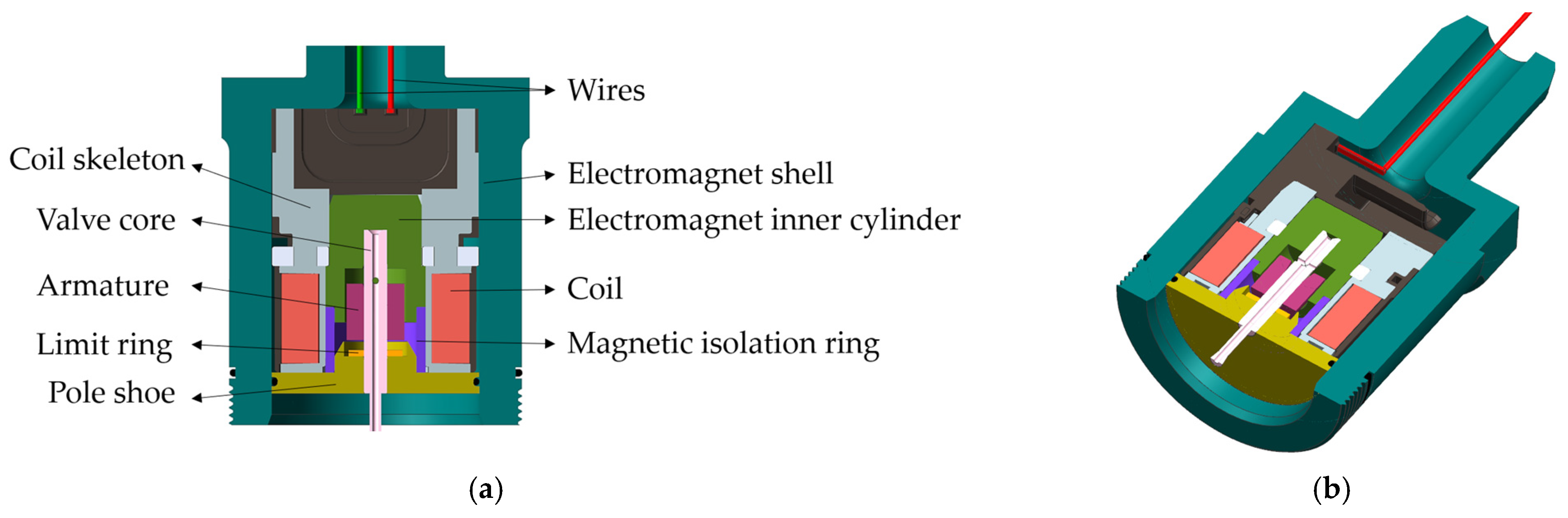
2.1. Structure of Proportional Electromagnets
2.2. Working Principle of Proportional Electromagnets
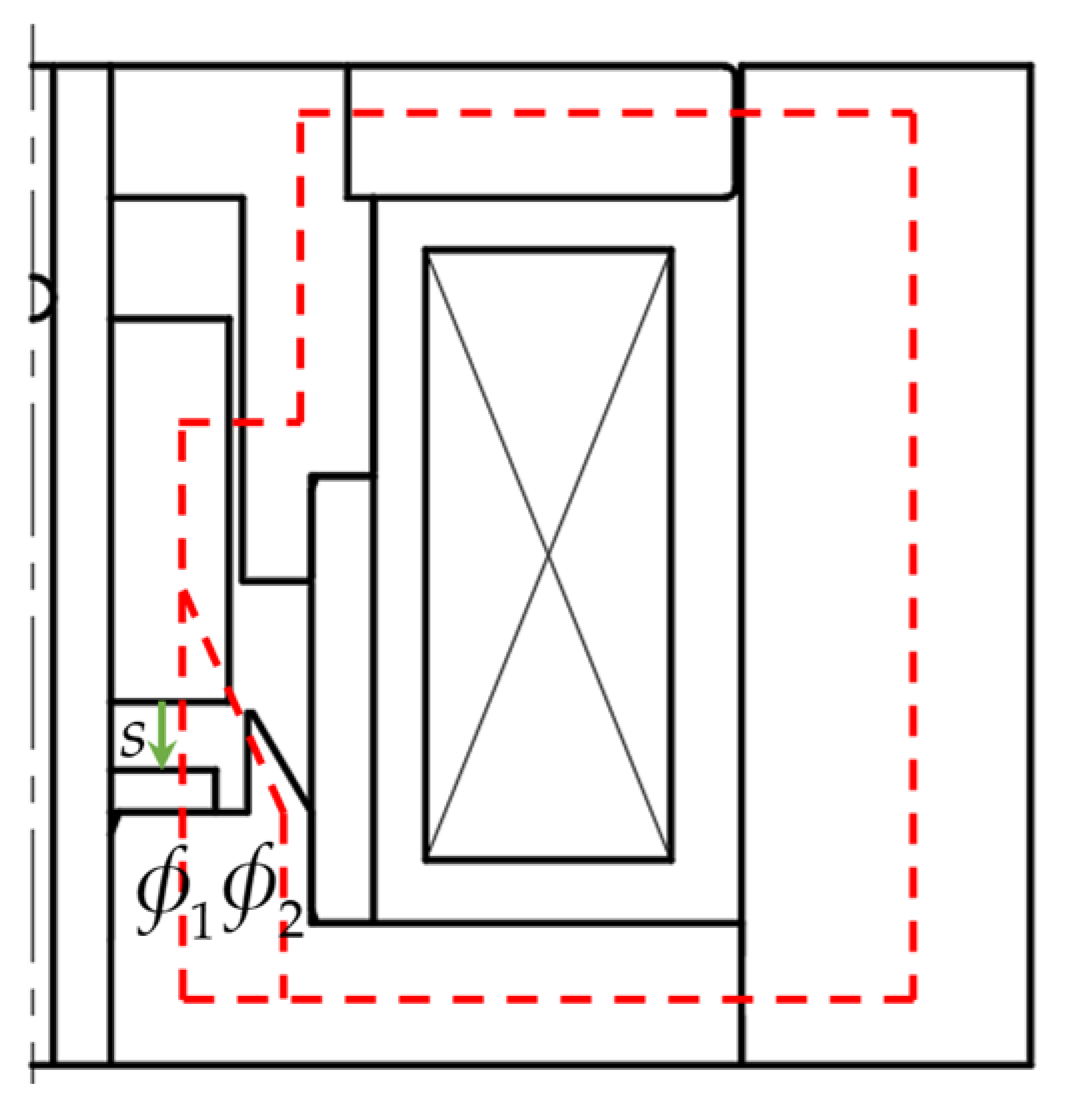
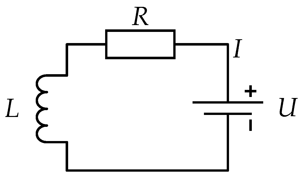
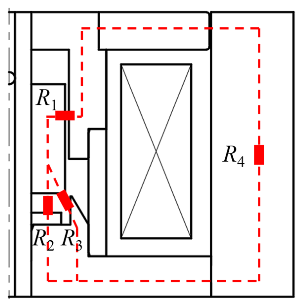
2.3. Mathematical Model of Electromagnetic Force
3. Parametric Analysis of Key Parameters of Electromagnet
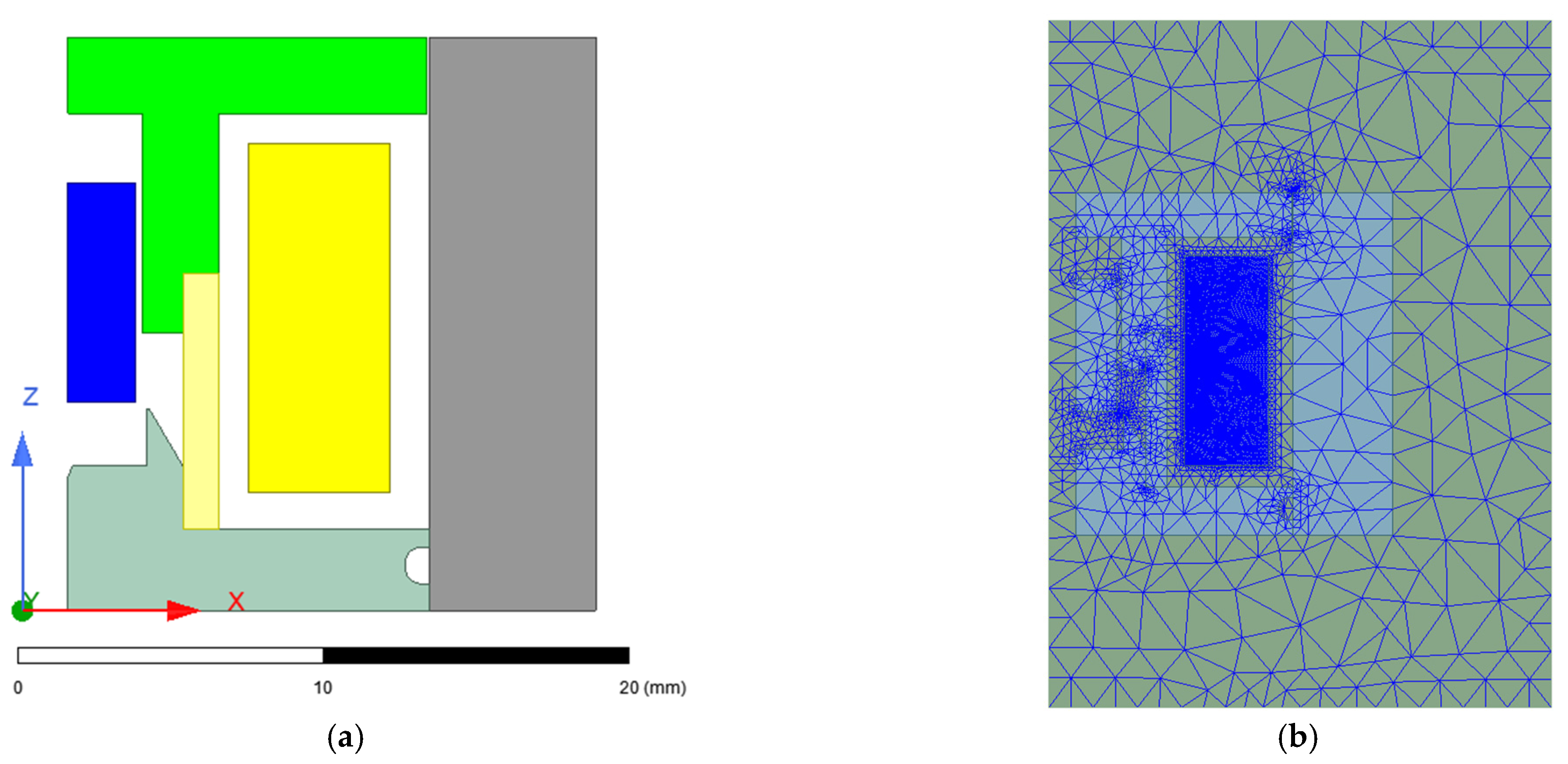
3.1. Simulation Settings
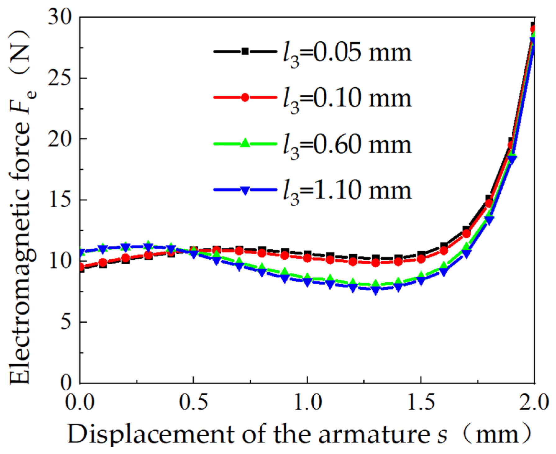
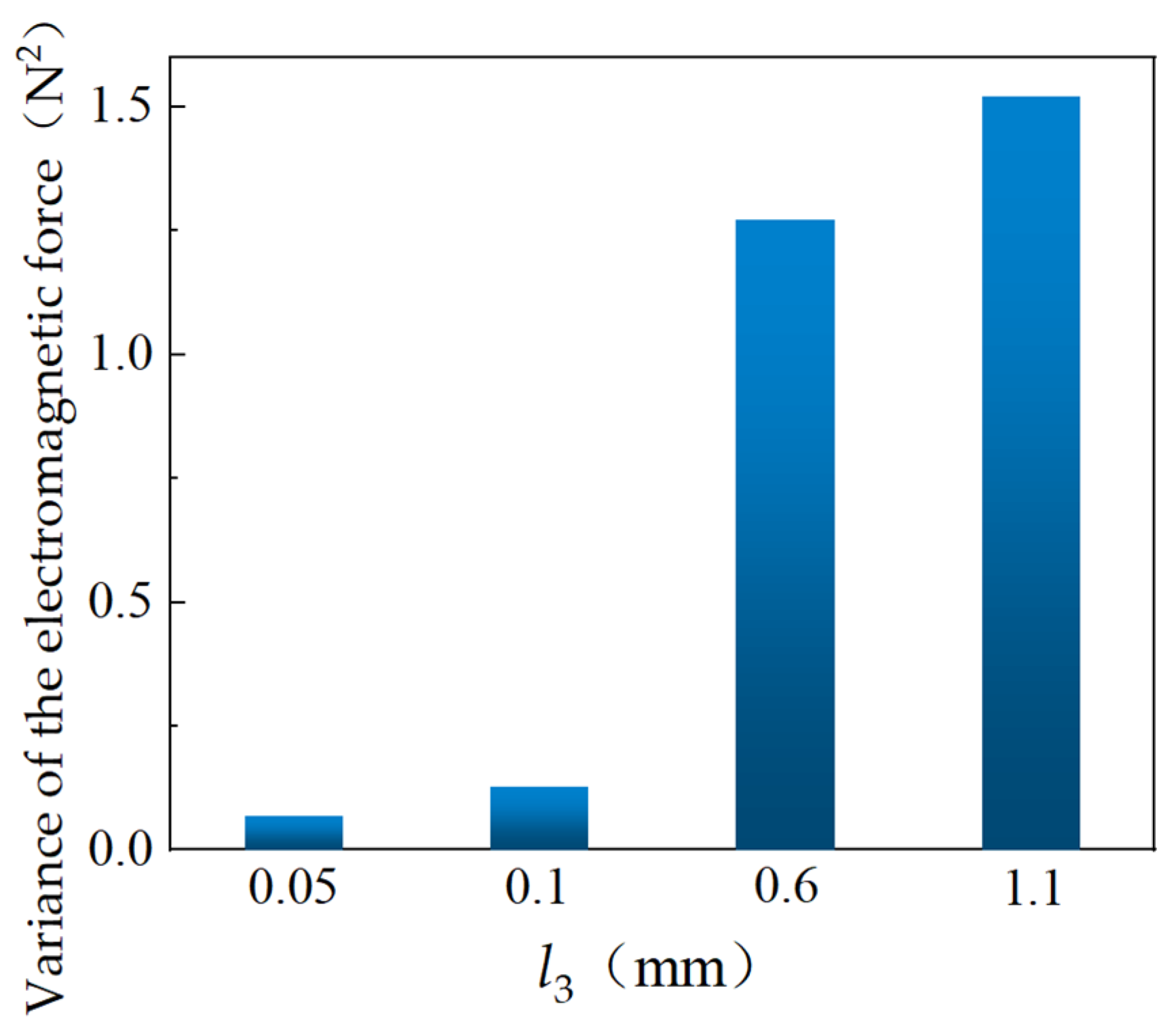
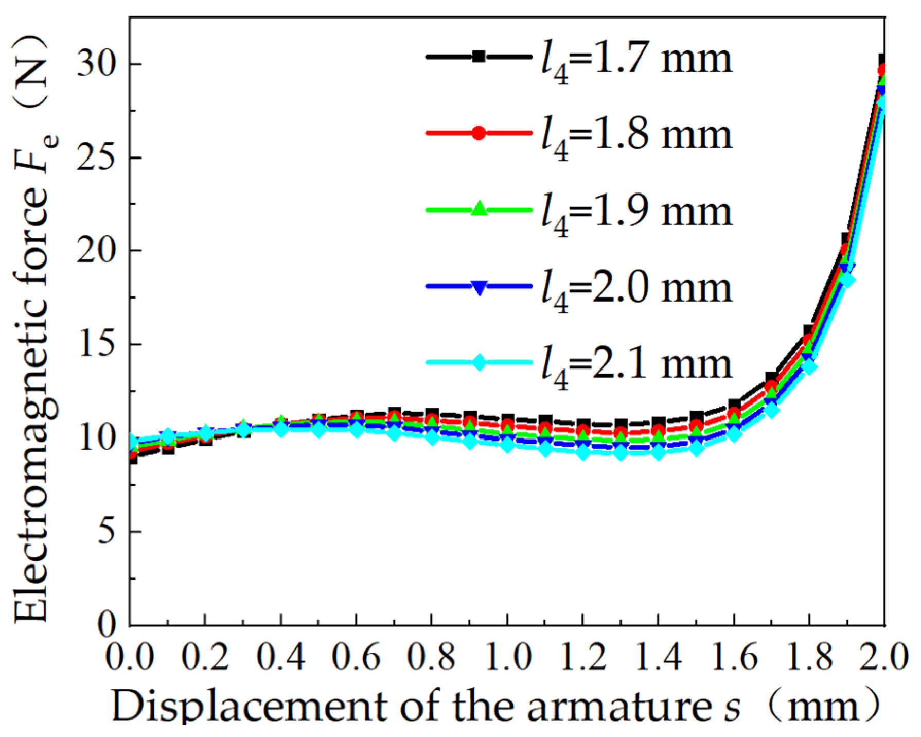
3.2. Parametric Simulation of Proportional Electromagnets
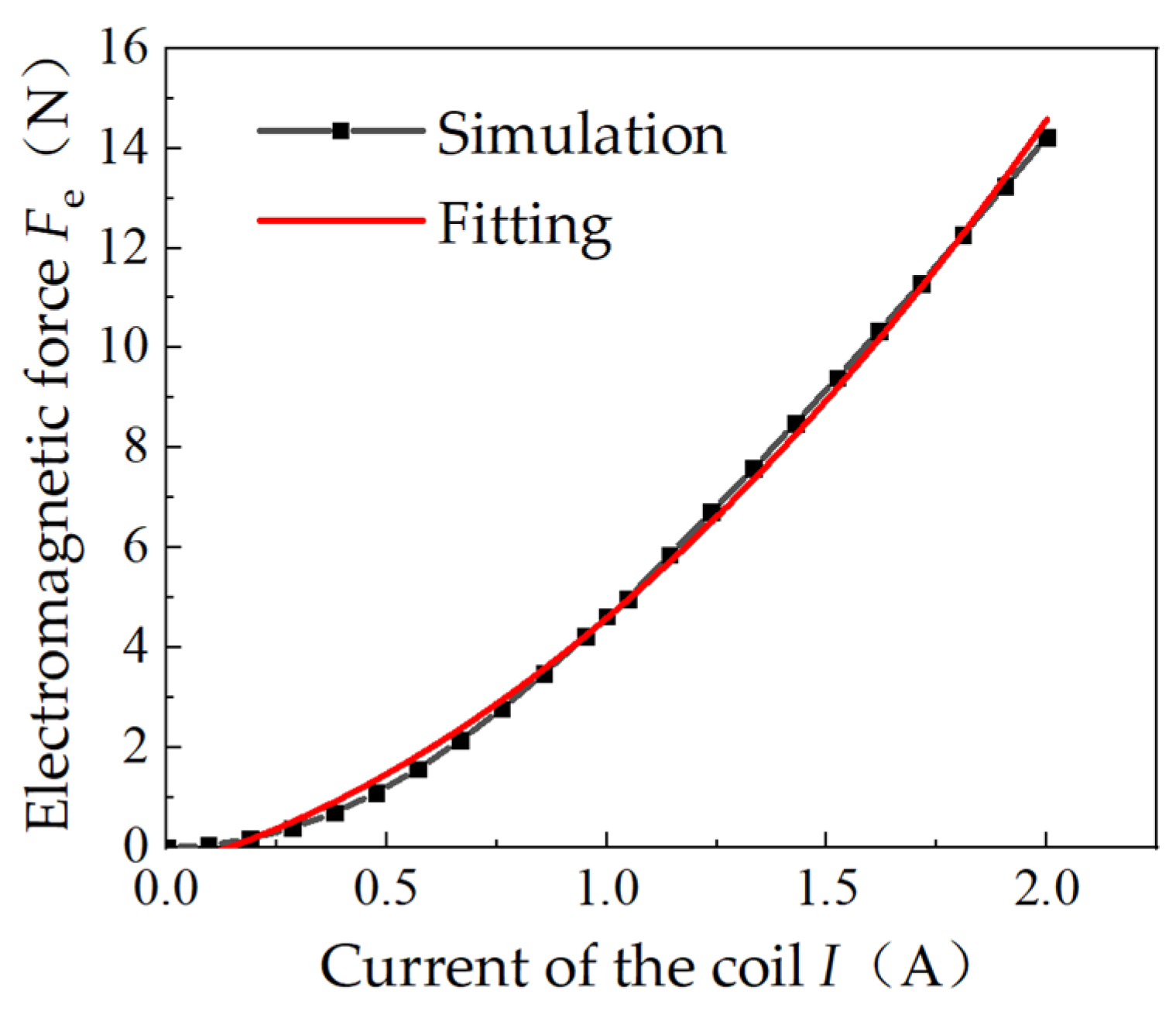
3.3. Electromagnetic Force Simulation
4. Test Verification of Proportional Electromagnets
4.1. Test Equipment
4.2. Test Scheme
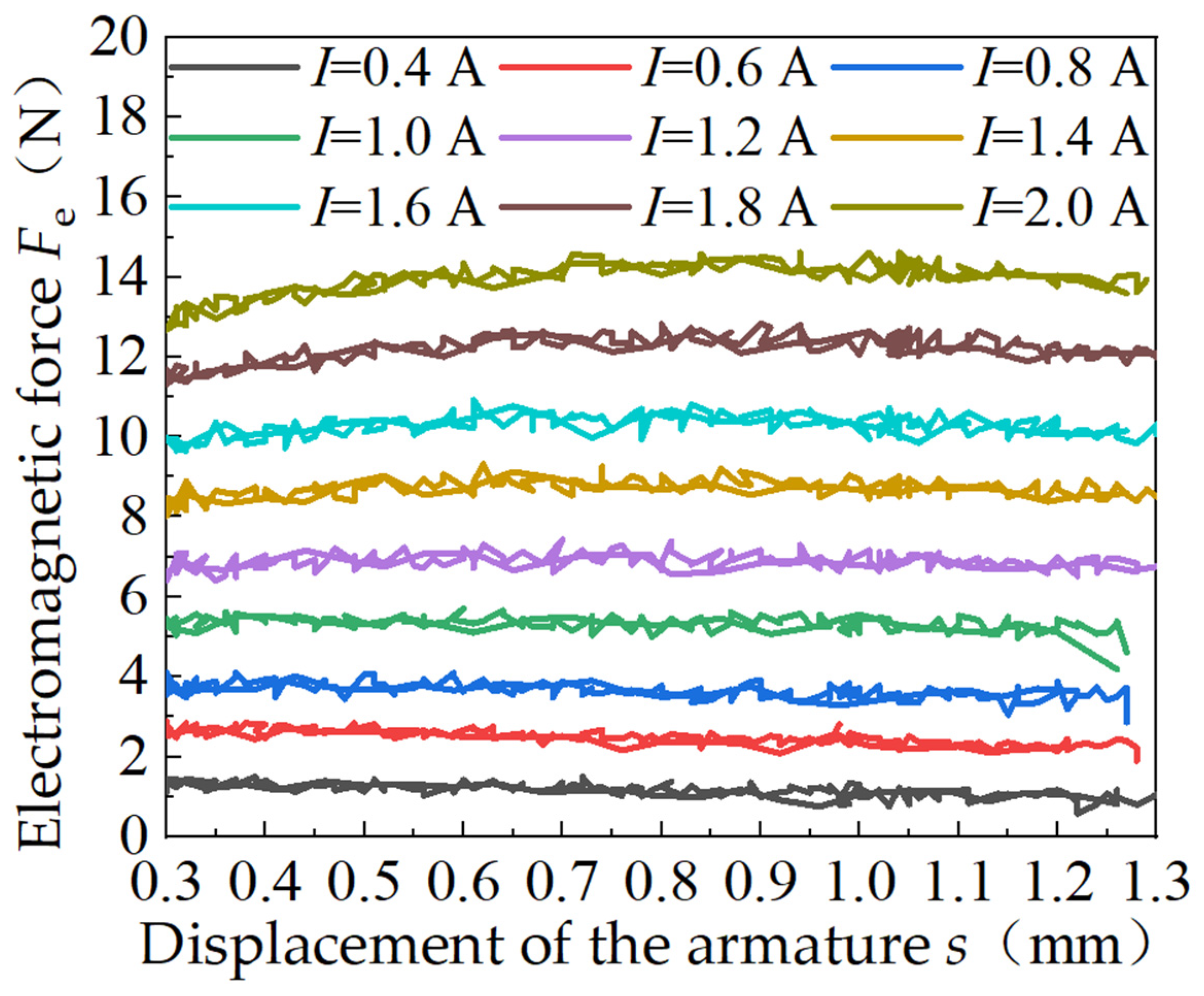
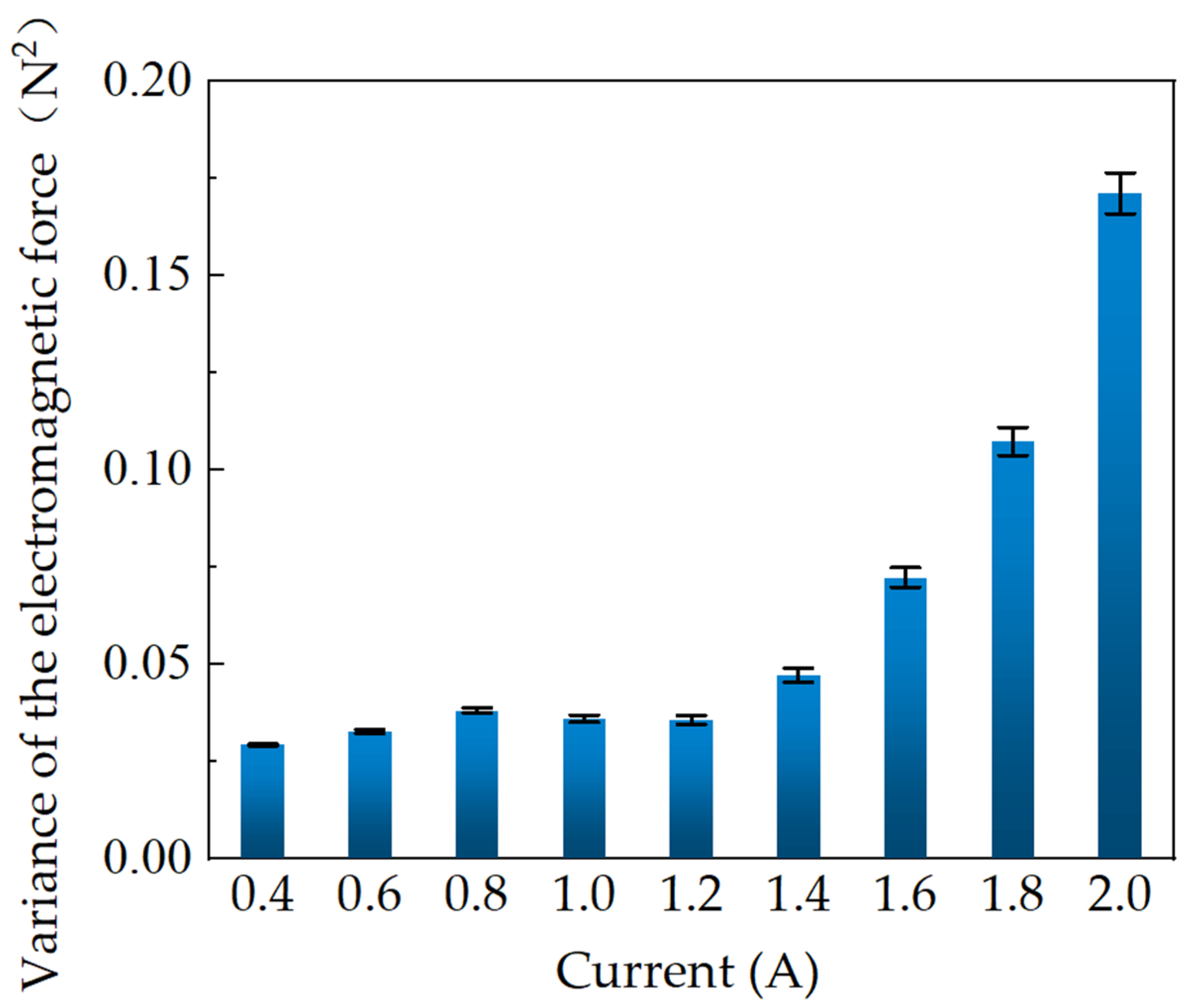
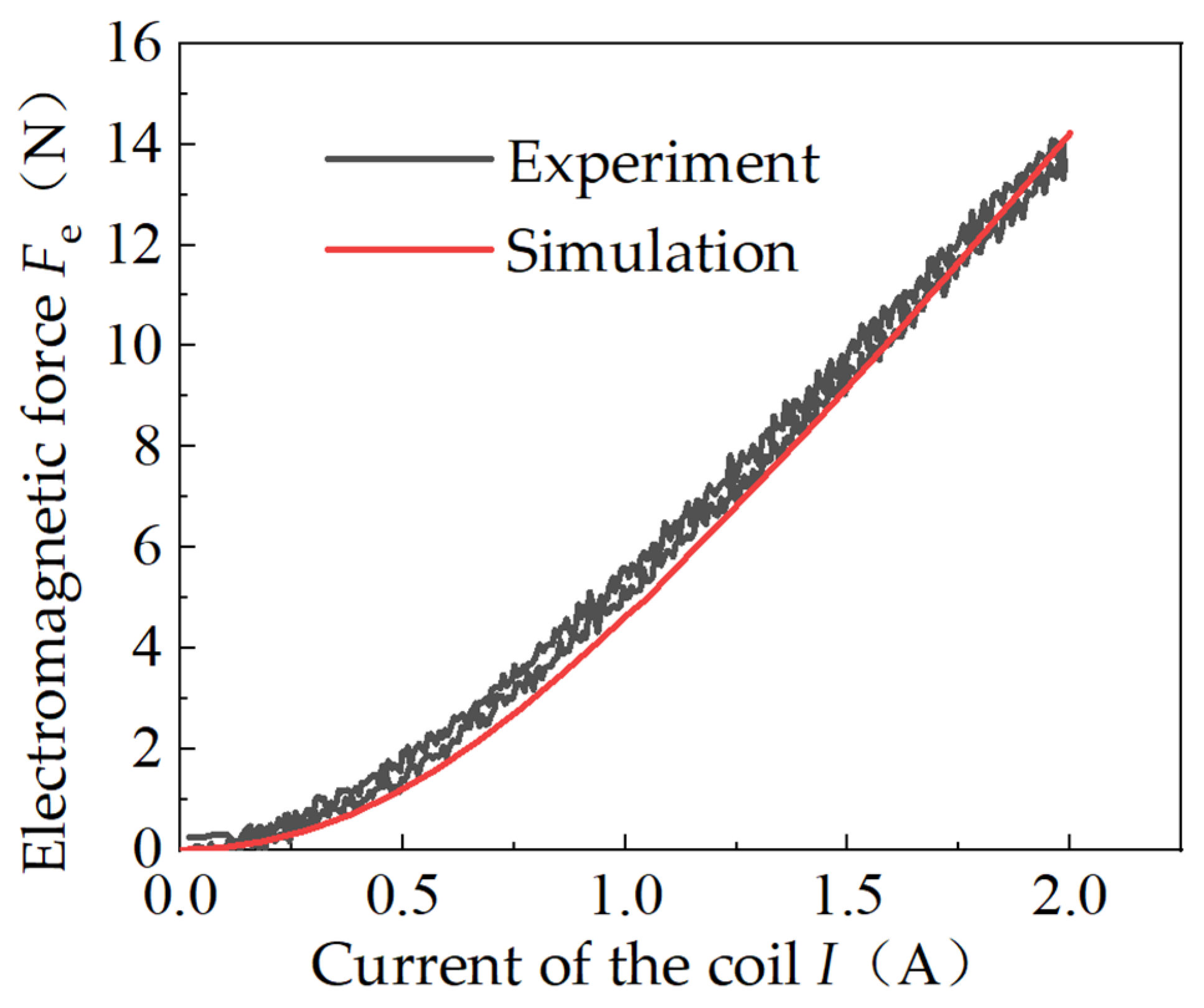
4.3. Test Results
5. Conclusions
Author Contributions
Funding
Data Availability Statement
Conflicts of Interest
References
- Xu, B.; Shen, J.; Liu, S.; Su, Q.; Zhang, J.H. Research and Development of Electro-hydraulic Control Valves Oriented to Industry 4.0: A Review. Chin. J. Mech. Eng. 2020, 33, 552–559. [Google Scholar] [CrossRef]
- Wang, H.; Chen, Z.; Huang, J.H.; Quan, L.; Zhao, B. Development of High-Speed On-Off Valves and Their Applications. Chin. J. Mech. Eng. 2022, 35, 37–57. [Google Scholar] [CrossRef]
- Zhao, J.G.; Luo, L.; Zhuo, Y.; Wang, M.H.; He, C.; Zhang, C.L.; Xie, G. Mechanical Characteristics and Miniaturization Design of the Electromagnetic Valve Used in Drilling Robots. Processes 2024, 12, 1685. [Google Scholar] [CrossRef]
- Pîslaru-Dănescu, L.; Morega, A.M.; Morega, M.; Dobre, A.A. Prototyping a Proportionally Electromagnetic Actuator with Wide Displacement of its Mobile Part. In Proceedings of the 2019 11th International Symposium on Advanced Topics in Electrical Engineering (ATEE), Bucharest, Romania, 28–30 March 2019; pp. 1–7. [Google Scholar]
- Davide, C.; Andrea, V. The Modeling of Electrohydraulic Proportional Valves. J. Dyn. Syst. Meas. Control 2011, 134, 021008. [Google Scholar]
- Lankin, M.V.; Lozin, O.I.; Lankina, M.Y. Magnetization Dynamic Characteristics Models for Hydraulic Drives of Proportional Electromagnets. Procedia Eng. 2017, 206, 443–448. [Google Scholar] [CrossRef]
- Wang, S.J.; Weng, Z.D.; Jin, B.; Cai, H.X. Multi-objective genetic algorithm optimization of linear proportional solenoid actuator. J. Braz. Soc. Mech. Sci. Eng. 2021, 43, 2. [Google Scholar] [CrossRef]
- Yue, D.L.; Li, L.F.; Wei, L.J.; Liu, Z.G.; Liu, C.; Zuo, X.K. Effects of Pulse Voltage Duration on Open-Close Dynamic Characteristics of Solenoid Screw-In Cartridge Valves. Processes 2021, 9, 1722. [Google Scholar] [CrossRef]
- Li, Y.C.; Li, R.C.; Yang, J.R.; Yu, X.D.; Xu, J.K. Review of Recent Advances in the Drive Method of Hydraulic Control Valve. Processes 2023, 11, 2537. [Google Scholar] [CrossRef]
- Wang, S.H.; Xiao, X.L.; Xiong, G.Y. Direct Current Electromagnets with Constant Traction Characteristic. Chin. J. Mech. Eng. 2008, 44, 244–247. [Google Scholar] [CrossRef]
- Shang, R.K.; Liu, P.; Quan, W.W.; Ouyang, Y.W. Comparative Analysis of Armature Structure on Constant Force Characteristics in Long-Stroke Moving-Iron Proportional Solenoid Actuator. Actuators 2024, 13, 408. [Google Scholar] [CrossRef]
- Xue, L.; Fan, X.; Tao, G.L. Development of test system for proportional electromagnet actuators’ performance. Mech. Electr. Eng. Mag. 2009, 26, 67–69. [Google Scholar]
- Xie, F.W.; Zhou, R.; Wang, D.S.; Ke, J.; Guo, X.J.; Nguyen, V.X. Simulation Study on Static and Dynamic Characteristics of Electromagnet for Electro-Hydraulic Proportional Valve Used in Shock Absorber. IEEE Access 2020, 8, 41870–41881. [Google Scholar] [CrossRef]
- Xu, J.N.; Kou, F.; Zhang, X.Q.; Wang, G.H. Modeling and testing for continuously adjustable damping shock absorber equipped with proportional solenoid valve. J. Mech. Sci. Technol. 2023, 37, 3851–3866. [Google Scholar] [CrossRef]
- Wu, W.; Wei, C.H.; Zhou, J.J.; Hu, J.B.; Yuan, S.H. Numerical and experimental nonlinear dynamics of a proportional pressure-regulating valve. Nonlinear Dyn. 2021, 103, 1415–1425. [Google Scholar] [CrossRef]
- Marian, L.; Lumír, H.; Adam, B.; Martin, V. Static and dynamic characteristics of proportional directional valve. EPJ Web. Conf. 2019, 213, 02052. [Google Scholar]
- Wang, S.; Weng, Z.; Jin, B. A performance improvement strategy for solenoid electromagnetic actuator in servo proportional valve. Appl. Sci. 2020, 10, 4352. [Google Scholar] [CrossRef]
- Yue, F.Y.; Guo, L.T.; Hao, L.; Wei, B. Study of a Bidirectional Proportional Electromagnet. Appl. Mech. Mater. 2013, 2218, 155–158. [Google Scholar]
- Yuan, X.J.; Ling, H.T.; Qiu, T.Y.; Zhou, J.W.; Zhao, R. Optimization for a proportional electro-magnet with high accuracy utilizing finite element method. Int. J. Appl. Electromagn. Mech. 2021, 65, 267–280. [Google Scholar] [CrossRef]
- Ercan, D.; Gürsel, Ş. Design and Analysis of a Proportional Electromagnet with Experimental Validation for Static and Dynamic Behavior. Preprints 2024, 2024101770. [Google Scholar] [CrossRef]
- Yang, L.; Gao, T.X.; Du, X.M.; Zhai, F.G.; Zhai, F.G.; Lu, C.; Kong, X.D. Electromagnetic Characteristics Analysis and Structure Optimization of High-Speed Fuel Electromagnets. Machines 2022, 10, 964. [Google Scholar] [CrossRef]
- Hong, Y.S.; Kwon, Y.C. Electromagnetic Analysis of a Flat-Type Proportional Solenoid by the Reluctance Method. Int. J. Precis. Eng. Manuf. 2006, 7, 46–51. [Google Scholar]
- Yu, Y.X.; Ke, S.D.; Jin, K.D. Structural parameters optimization for a proportional solenoid. Int. J. Simul. Model. 2020, 19, 689–700. [Google Scholar] [CrossRef]
- Liu, P.; Ouyang, Y.W.; Quan, W.W. Multi-objective optimization of a long-stroke moving-iron proportional solenoid actuator. Micromachines 2024, 15, 58. [Google Scholar] [CrossRef] [PubMed]
- Tang, J.H.; Zuo, Y.Y. The Design and Magnetic Field Analysis of a Double Rotor Permanent Magnet Braking Device. Processes 2022, 10, 346. [Google Scholar] [CrossRef]
- Wang, Y.B.; Chu, L.; Ma, W.T.; Cai, J.W.; Bai, G.J. Research on Hydraulic Response Characteristics of Inlet Valve Used in Hydraulic Braking System. Appl. Mech. Mater. 2014, 2963, 175–179. [Google Scholar] [CrossRef]


| Part | Material |
|---|---|
| Electromagnet shell | 1215 steel |
| Pole shoe | 1215 steel |
| Electromagnet inner cylinder | 1215 steel |
| Part of the coil skeleton | 1215 steel |
| Armature | 1215 steel |
| Magnetic isolation ring | Copper |
| Coil | Copper |
| Parameter | Parameter Value/mm |
|---|---|
| Valve core radius r1 | 1.50 |
| The radius of the armature r2 | 3.25 |
| The internal radius of electromagnet inner cylinder r3 | 4.00 |
| Basin bottom radius r4 | 4.10 |
| The maximum length of the front surface of the armature from the pole shoe basin bottom l1 | 2.10 |
| The air gap length between the armature and electromagnet inner cylinder l2 | 5.00 |
| Guide angle width l3 | 0.10 |
| Basin mouth depth l4 | 1.90 |
Disclaimer/Publisher’s Note: The statements, opinions and data contained in all publications are solely those of the individual author(s) and contributor(s) and not of MDPI and/or the editor(s). MDPI and/or the editor(s) disclaim responsibility for any injury to people or property resulting from any ideas, methods, instructions or products referred to in the content. |
© 2024 by the authors. Licensee MDPI, Basel, Switzerland. This article is an open access article distributed under the terms and conditions of the Creative Commons Attribution (CC BY) license (https://creativecommons.org/licenses/by/4.0/).
Share and Cite
Ren, W.; Wu, L.; Zhang, W.; Jiang, P.; Wang, Z.; Luo, C.; Guo, J.; Liu, C.; Wei, Y.; Chen, Z.; et al. Design and Parametric Analysis of the Constant Force Characteristics of the Electromagnet for Hydraulic Valves. Processes 2024, 12, 2632. https://doi.org/10.3390/pr12122632
Ren W, Wu L, Zhang W, Jiang P, Wang Z, Luo C, Guo J, Liu C, Wei Y, Chen Z, et al. Design and Parametric Analysis of the Constant Force Characteristics of the Electromagnet for Hydraulic Valves. Processes. 2024; 12(12):2632. https://doi.org/10.3390/pr12122632
Chicago/Turabian StyleRen, Wang, Liujie Wu, Wei Zhang, Pengfei Jiang, Ziyue Wang, Chao Luo, Jichang Guo, Chang Liu, Yaozhong Wei, Zhiliang Chen, and et al. 2024. "Design and Parametric Analysis of the Constant Force Characteristics of the Electromagnet for Hydraulic Valves" Processes 12, no. 12: 2632. https://doi.org/10.3390/pr12122632
APA StyleRen, W., Wu, L., Zhang, W., Jiang, P., Wang, Z., Luo, C., Guo, J., Liu, C., Wei, Y., Chen, Z., He, Z., Liu, Y., Yu, T., Song, Y., & Yu, B. (2024). Design and Parametric Analysis of the Constant Force Characteristics of the Electromagnet for Hydraulic Valves. Processes, 12(12), 2632. https://doi.org/10.3390/pr12122632