Article

Investigation of a Hydrophobic Sputtered Cu Electrode to Electrocatalyze CO2 Towards a C2+ Product: The Effect of Substrate and Catalyst Thickness

1
State Key Lab of Clean Energy Utilization, Zhejiang University, Hangzhou 310027, China
2
Baima Lake Lab, Hangzhou 310053, China
3
China Three Gorges Renewables (Group) Co., Ltd. Construction Management Branch, Beijing 100032, China
4
Zhejiang Zheneng Technology and Environment Group Co., Ltd., Hangzhou 310003, China
*
Authors to whom correspondence should be addressed.
Processes 2024, 12(11), 2374; https://doi.org/10.3390/pr12112374
Submission received: 18 September 2024 / Revised: 24 October 2024 / Accepted: 26 October 2024 / Published: 29 October 2024

Abstract

:
The overuse of fossil fuels has resulted in massive CO2 emissions, causing global environmental problems. Renewable energy-driven electrocatalysis, which can convert CO2 into fuels and chemicals, is considered an emerging technology for carbon resource recycling. Cu-based catalysts sputtered on hydrophobic carbon paper and a polytetrafluoroethylene (PTFE) membrane were comparatively investigated, while the effect of the thickness of the Cu sputtering layer on the electrocatalytic CO2 reduction performance was investigated. Additionally, the effect of substrate properties on the distribution and morphology of sputtered Cu metal was investigated by SEM and XRD. With carbon paper as the substrate, the highest FEC2+ achieved was 70% at 200 mA/cm2, while the maximum value of FEC2+ on the Cu/PTFE electrode was realized with a Cu thickness of 400 nm (72%). Additionally, the PTFE substrate demonstrated a better inhibiting effect on HER, with a lower FEH2 and high FEC2+ over different applied current densities.

1. Introduction

Rapid economic and social development is heavily reliant on the utilization of fossil fuel-based energy [1]. However, massive CO2 emissions derived from the overuse of fossil fuel-based energy have triggered severe environmental problems such as climate change and ocean acidification, leading to increasing attention from the public around the world [2,3]. By 2023, approximately 110 Mt of CO2 was released into the atmosphere every day. Therefore, it is crucial to mitigate the emission of CO2 by developing advanced utilization technologies. Electrocatalytic CO2 reduction reaction (CO2RR) is considered an emerging method for carbon resource recycling and can be powered by renewables and effectively convert CO2 into high-value chemicals and fuels.
Nevertheless, CO2RR involves a multi-electron transfer process, with different pathways leading to various products [4,5,6]. Among these, the electrochemical reduction of CO2 to C2+ products holds great promise, particularly in the production of ethylene (C2H4) and ethanol (C2H5OH), both of which are vital chemical products [7,8,9]. Thus, the development of efficient electrocatalyst materials for large-scale production of C2+ products is significantly important. According to previous studies, different materials have been employed for CO2RR based on their intrinsic activities. For instance, the weak adsorption of *H and *CO by Au, Ag, and Zn contributes to excellent CO selectivity [10,11,12], while monometallic Sn and In with strong O affinities and weak H affinities are prone to generate HCOOH [13,14,15]. Copper stands out for its capability to electrocatalytically convert CO2 into high value-added hydrocarbons via deep reduction of *CO intermediates [16,17,18]. Numerous studies have explored the types of Cu metal catalysts, including oxide-derived Cu [19,20], halide-derived Cu [21], and Cu bimetallic catalysts [22,23], as well as preparation methods such as electrodeposition [24], high-temperature pyrolysis [25], replacement reaction [26], and magnetron sputtering [27,28,29]. As a type of physical vapor deposition, magnetron sputtering is generally used for semiconductors, insulators, and other multi-functional material preparation, with the advantages of easy control, a large coating area, and strong adhesion [30,31]. Recently, magnetron sputtering-based Cu electrocatalysts have been widely used on carbon paper and polytetrafluoroethylene (PTFE) as substrate for CO2RR, especially using flow cells or membrane electrode assembly cells.
However, the detailed influence of the substrate is seldom analyzed compared to conventional thermal processes. The substrate plays an important role in providing a multi-functional interface for mass transfer and catalyst support to facilitate electrochemical reactions. For instance, Hu et al. [32] prepared a La(OH)3/Cu catalyst with carbon paper as a substrate, demonstrating a remarkable Faradaic efficiency (FEC2+) of 71%. Although carbon paper exhibits excellent electrical conductivity, it suffers from severe flooding due to the charging effect, which deteriorates its hydrophobicity with prominent hydrogen evolution reaction (HER). Therefore, hydrophobic PFTE has recently been proposed as a potential substrate to avoid flooding and suppress HER. For instance, John Pellessier et al. [33] used prepared polymer-modified Cu catalysts on PTFE, demonstrating a Faradaic efficiency of 78% for C2+ products.
In this study, Cu sputtering on different substrates (e.g., carbon paper and PTFE) was comparatively investigated for electrocatalytic CO2 reduction. The structure and morphology of prepared electrocatalysts were characterized by XRD and SEM. Furthermore, the hydrophobicity of the prepared Cu sputtering electrodes was analyzed via contact angle measurement. The results demonstrated that PTFE could better inhibit the HER despite its lower hydrophobicity compared to carbon paper. The highest FE of C2+ products can exceed 70% in alkaline flow cells, while the thickness of Cu layers had a prominent effect on the product distribution and C2H4/C2H5OH ratio.

2. Materials and Methods

2.1. Cathode Electrode Preparation

Carbon paper (SGL CARBON, SGL36BB, purchased from SCI Materials Hub, Wuhu, China) and PTFE (Zhongxingweiye, Co., Ltd., Beijing, China) were used as the substrates for magnetron sputtering, with pure Cu (99.9%) as the target material. The sputtering power was set at 100 W with a sputtering rate of 16 nm/min. The sputtered Cu layers with thicknesses of 100 nm, 200 nm, 300 nm, 400 nm, and 500 nm were obtained by adjusting the sputtering duration (375 s, 750 s, 1125 s, 1500 s, and 1875 s, respectively). The carbon paper-based Cu electrode was named Cu/CP, and the PTFE-based Cu electrode was named Cu/PTFE.

2.2. Anode Electrode Preparation

First, 0.5 mm-thick nickel foam was cut into a 3 cm × 3 cm square. Then, it was immersed into a solution of 3 mM Ni(NO3)2∙6H2O and 3 mM Fe(NO3)3∙9H2O. The electrodeposition was performed for 300 s at −1 V vs. Ag/AgCl, followed by rinsing with deionized water and ethanol, respectively. Eventually, the prepared electrode was dried at room temperature for CO2RR.

2.3. Characterization

An X-ray diffractometer (XRD, Rigaku SmartLab SE, Tokyo, Japan) was used to analyze the phase structure and crystallinity of the prepared catalysts via an X-ray line source with a scanning speed of 2° min−1 and a scanning angle in the range of 20°–80°. Scanning electron microscopy (SEM, ZEISS Gemini SEM 300, Baden-Württemberg, Germany) was used to characterize the surface micromorphology of the catalysts. Focused ion beam scanning electron microscopy (FIB-SEM) was used to characterize the planar and cross-sectional surfaces of the Cu-based electrodes at high resolution. The surface structure of the samples was observed using an SE2 detector inside the chamber, and high-resolution imaging was conducted using an Inlens/ESB detector inside the barrel. The contact angle test (Video Contact Angle Measuring Instrument, Dataphysics, Filderstadt, Germany) was performed using an OCA20 contact angle tester to evaluate the hydrophilicity.

2.4. Electrochemical CO2RR and Product Analysis

A typical three-electrode system was used for CO2RR in a homemade flow cell, with a sputtered Cu electrode as the working electrode, a mercury–mercury oxide (Hg/HgO) electrode as the reference electrode, and an NiFe-loaded nickel foam electrode as the counter electrode, respectively. An anion exchange membrane (FuMA-Tech FAB-130, Baden-Württemberg, Germany) was used to separate the anodic and cathodic chamber. The cathode and anode electrolytes were 1 M KOH, and the flow rates of the electrolytes were controlled by a peristaltic pump at 3 mL/min and 10 mL/min, respectively. The CO2 flow rate was controlled by a mass flow meter at 30 mL/min, while the gas flow rate after the reaction was further verified by a soap film flow meter. An electrochemical workstation (ChenHua, 1400 C, Shanghai, China) was used, and all potentials were converted into the reversible hydrogen electrode (RHE). The gas products during CO2RR were determined on-line by a gas chromatographer (GC, FULI 9790, Taizhou, China) equipped with a thermal conductivity detector (TCD) for H2 and CO measurement and a flame ionization detector (FID) to measure the CH4 and C2+ products. The liquid products were collected individually each time and evaluated by nuclear magnetic resonance hydrogen spectroscopy (NMR), while the spectra were analyzed via a Bruker 400 MHz spectrometer using DMSO as the internal standard.

3. Results

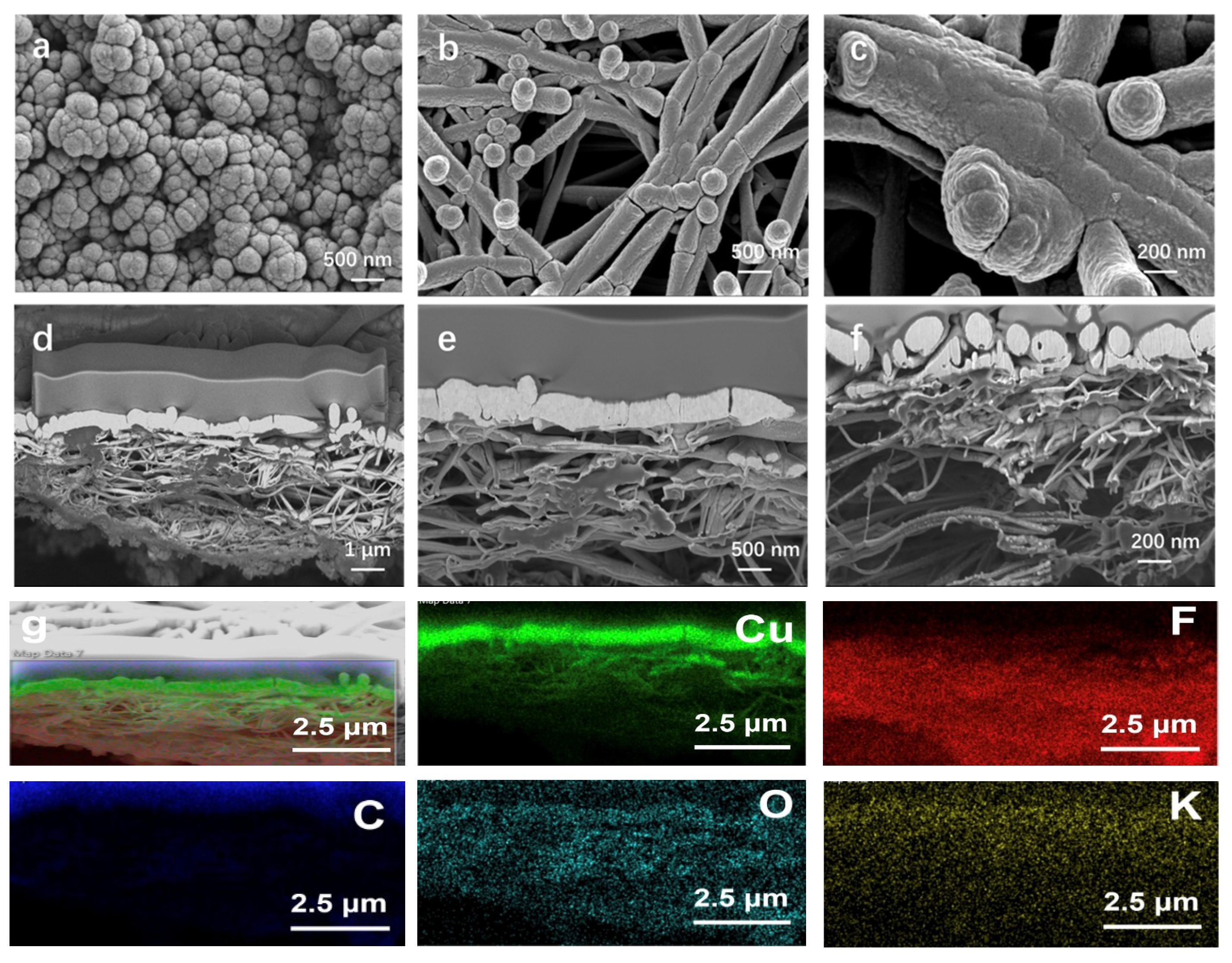
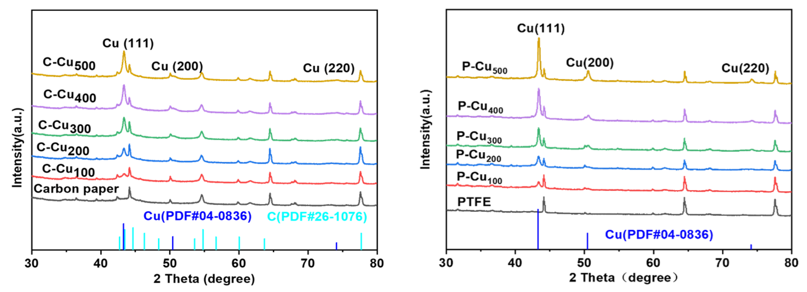
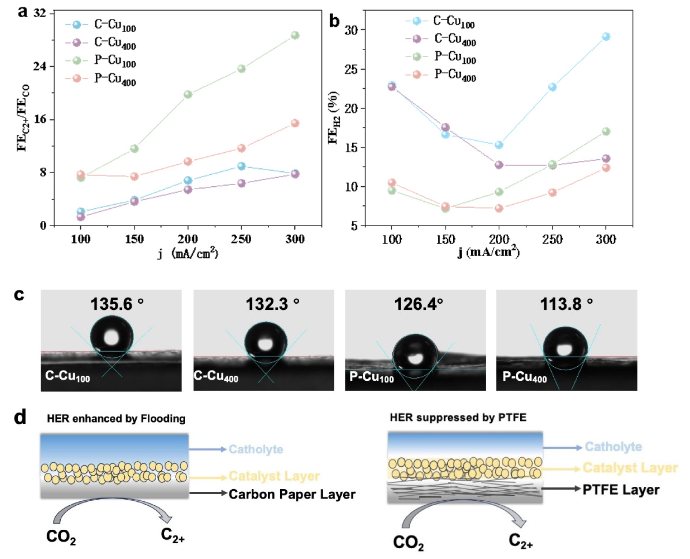
3.1. Characterization of the Sputtered Cu Electrocatalyst on Carbon and PTFE

In this study, Cu-based electrodes were successfully fabricated by sputtering Cu onto hydrophobic carbon paper and PTFE membranes. The sputtering thickness, ranging from 100 nm to 500 nm, was precisely controlled by adjusting the sputtering duration. As shown in Figure 1, the morphology of the Cu electrodes varied depending on the substrate. When carbon paper was used as the substrate, the Cu nanoparticles exhibited a tendency to increase in size and coalesce with increasing sputtering time. The average particle diameter approached approximately 500 nm at a sputtering thickness of 500 nm (Figure S1). In contrast, a dendritic structure was observed for Cu sputtered on the PTFE membrane. The original PTFE substrate exhibited fibrous structures with a diameter of approximately 100 nm, and the maximum pore size in the channels was ~1 μm. With prolonged sputtering, the Cu grew conformally along the PTFE substrate, gradually increasing in diameter, while the overall pore structure of the PTFE was maintained despite a reduction in the pore size of the electrode (Figure S2). Additionally, SEM-FIB technology was employed to perform cross-sectional imaging of the Cu/PTFE electrode. As shown in Figure 1d–f, a rich porous structure was observed within the PTFE layer, with a dense Cu catalyst layer, approximately 400 nm thick, deposited on top. At the interface between the Cu catalyst and PTFE layers, Cu was found to wrap around the PTFE fibers, as confirmed by elemental mapping through energy-dispersive X-ray spectroscopy (EDS). It is hypothesized that as the Cu catalyst further infiltrates the PTFE layer, the hydrophobicity of the membrane may degrade, potentially affecting the reaction within the PTFE matrix.
The phase structure of the Cu electrode was characterized using X-ray diffraction (XRD), and the resulting spectra, as shown in Figure 2, exhibited minimal variation regardless of the substrate material. By comparing the data with standard reference cards (Cu#PDF04-0836, Cu#PDF26-1027), the primary crystallographic planes of the sputtered Cu were identified as Cu (111), Cu (200), and Cu (220). As the sputtering thickness increased, the intensity of the diffraction peak at 43.32°, corresponding to the Cu (111) crystal plane, was significantly enhanced. In contrast, the intensity increases for the Cu (200) plane at 50.45° and the Cu (220) plane at 74.12° were less pronounced. This suggests that with the increasing thickness of the magnetron-sputtered Cu, a preferential orientation along the Cu (111) plane began to develop.

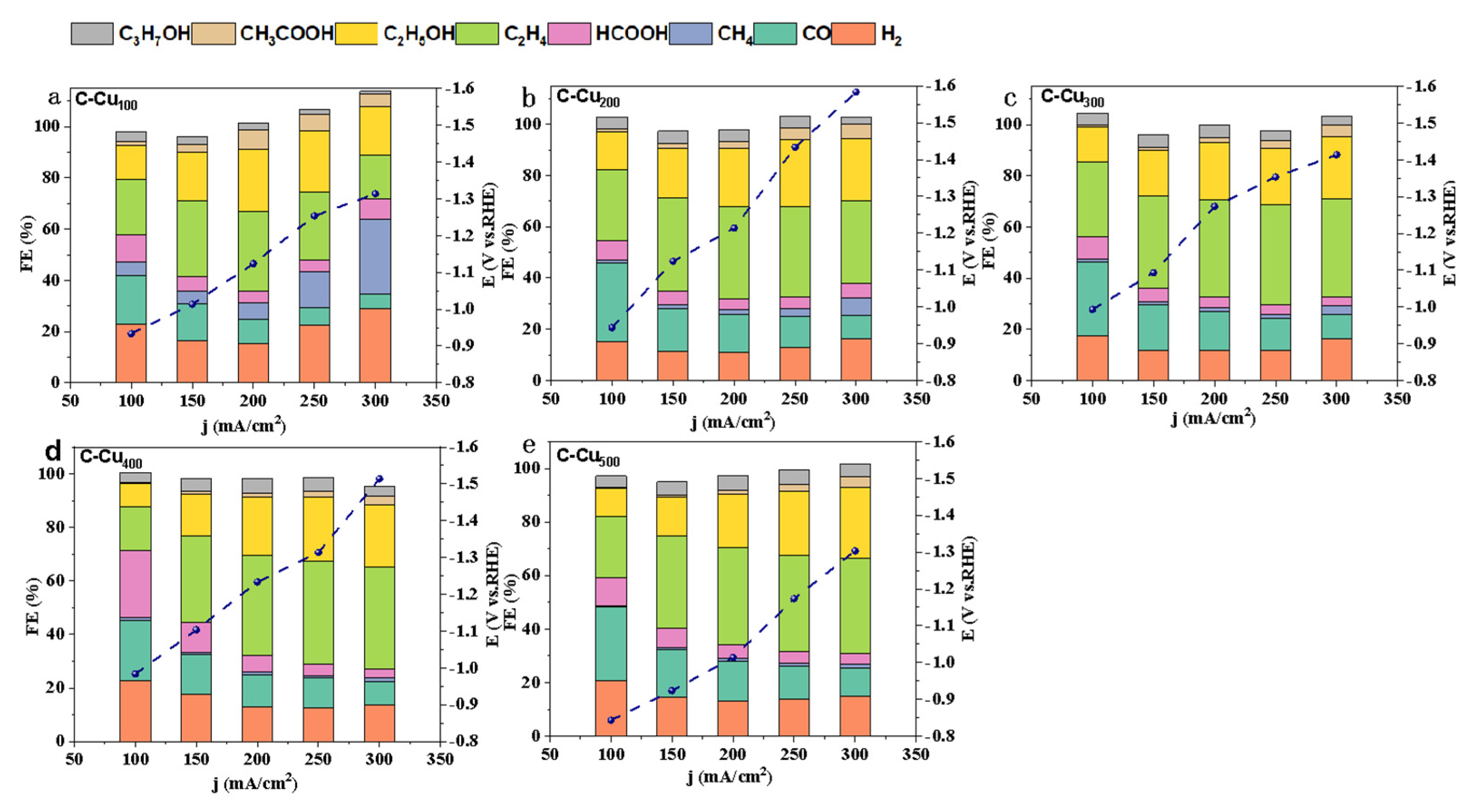
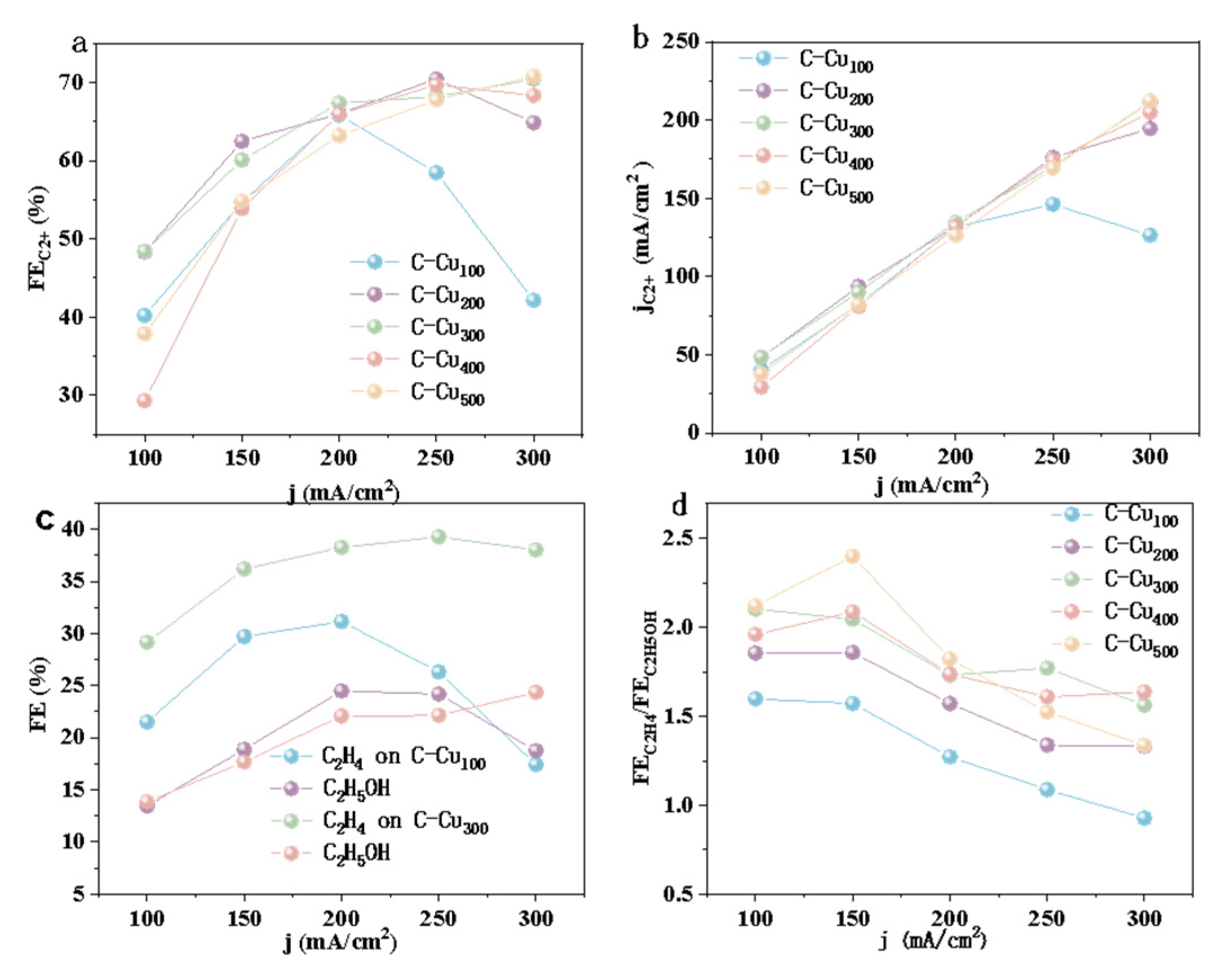
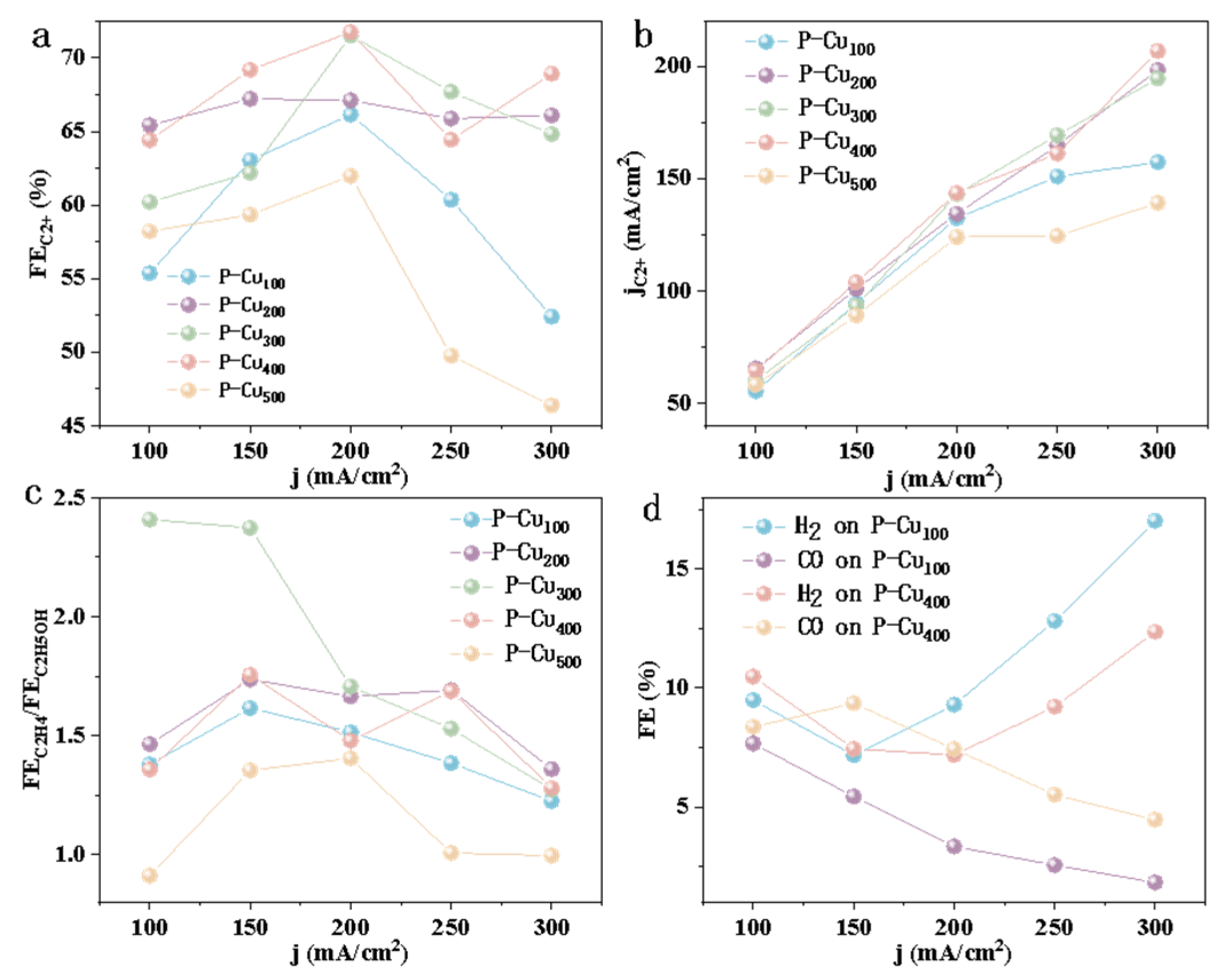
3.2. Electrocatalytic Activity of CO2RR

The electrocatalytic CO2 reduction performance of sputtered Cu/CP and Cu/PTFE electrodes with varying sputtering thicknesses was assessed in an alkaline flow electrolytic cell, with current densities ranging from 100 to 300 mA/cm2 as shown in Figure 3a–e. Overall, as the applied cathodic current density increased, the Faradaic efficiency (FE) for CO (FECO) decreased, while the FE for C2+ products (FEC2+) increased. This trend can be attributed to the enhanced reaction kinetics of C–C coupling, leading to greater C2+ product formation as more *CO intermediates are consumed at higher negative operating currents.
For the Cu/CP electrode with a 100 nm sputtering thickness (C-Cu100), FEH2 initially decreased from 23% to 15% before rising to 29% as the current density increased from 100 to 300 mA/cm2. Concurrently, FECO dropped from 19% to 5%, while FECH4 rose from 5% to 30%. At a current density of 200 mA/cm2, FEC2H4, FECH3COOH, and FEC2H5OH were 31%, 7%, and 24%, respectively, with the total FEC2+ reaching a maximum value of 66%. Upon increasing the Cu sputtering thickness to 200 nm, a significant suppression of hydrogen evolution reaction (HER) was observed, with FEH2 remaining below 11% within the 150–250 mA/cm2 range. FECO also decreased from 31% to 9%, while FEC2+ increased from 48% at 100 mA/cm2 to 65% at 300 mA/cm2, reaching a maximum of 70% at 250 mA/cm2. The product distribution and electrocatalytic CO2 reduction trends for C-Cu300, C-Cu400, and C-Cu500 electrodes were similar to those of C-Cu200.
As the current density increased from 100 to 300 mA/cm2, the Faradaic efficiency for C2+ products initially rose sharply and then reached saturation for Cu electrodes with thicknesses greater than 200 nm. However, as shown in Figure 4a, the performance of thinner Cu/CP electrodes degraded significantly under the same conditions. Similarly, the partial current density for C2+ products exhibited an almost linear increase with current density. At 300 mA/cm2, the C-Cu500 electrode achieved the highest partial current density for C2+ products, reaching 212.34 mA/cm2, which was 1.68 times higher than that of the C-Cu100 electrode. This suggests that increasing the sputtering layer thickness provides a greater number of active sites, which represents the range of the actual three-phase interface (TPB). The TPB can be effectively regulated according to the wetting state. The wetting state can be divided into the Cassie state, the Cassie–Wenzel coexistent state, and the Wenzel state [34]. The Cassie–Wenzel coexistence state was favorable to increasing the number of actual active sites, in which a rich TPB was formed on the catalyst layer, and the active sites were fully exposed to the local environment to realize high efficiency reactions [35,36]. When the Cu layer is thin, the TPB is limited, with few effective sites. When the Cu layer is too thick, the gas cannot pass through the solid to contact the liquid, thus reducing the TPB region.
The partial current densities of the C-Cu300 and C-Cu400 electrodes also exceeded 200 mA/cm2, similar to the C-Cu500 electrode, indicating only a slight increase in active sites with further increases in the sputtering layer thickness (Figure 4b).
The C2+ products for the sputtered Cu electrodes on the carbon paper substrate were predominantly C2H4 and C2H5OH. A comparison of the C-Cu100 and C-Cu300 electrodes revealed that C2H4 selectivity ranged from 17% to 31% for C-Cu100 and from 29% to 39% for C-Cu300. Similarly, C2H5OH selectivity ranged from 13% to 24% for C-Cu100 and from 14% to 24% for C-Cu300 (Figure 4c). Notably, the FEC2H4 for C-Cu300 was significantly higher than that for C-Cu100 and remained stable even at the high current density of 300 mA/cm2. Furthermore, as shown in Figure 4d, the C2H4/C2H5OH ratio in terms of Faradaic efficiency increased progressively with sputtering layer thickness but decreased with rising current density.
The CO2 reduction performance of Cu/PTFE electrodes was also evaluated. Figure 5a–e shows the distribution of FEH2, FECO, and FEC2+ for Cu/PTFE electrodes with varying sputtering thicknesses as a function of current density. As the current density increased from 100 to 300 mA/cm2, FECO gradually decreased, while FEC2+ increased, following a trend similar to that observed for Cu/CP electrodes. The acceleration of C–C coupling kinetics at higher current densities favored the formation of C2+ products. For the P-Cu200 electrode, FECO decreased from 13% at 100 mA/cm2 to 4% at 300 mA/cm2, while FEC2+ increased from 65% to 66%. Across all Cu/PTFE electrodes, the highest C2+ selectivity was achieved at a current density of 200 mA/cm2, with FEC2+ values of 66%, 67%, 72%, 72%, and 62% for P-Cu100, P-Cu200, P-Cu300, P-Cu400, and P-Cu500, respectively (Figure 5e).
It is noteworthy that thicker sputtering layers may reduce pore sizes, hindering the diffusion of CO2 and H2O and consequently decreasing the electrocatalytic CO2RR activity. Additionally, higher current densities were found to promote CH4 formation, particularly for P-Cu100 and P-Cu500 electrodes. The FECH4 of the P-Cu100 electrode increased from 1% to 9%, while that of the P-Cu500 electrode increased from 0.1% to 5%, indicating that enhanced protonation by *H likely contributed to CH4 generation. Compared to Cu/CP electrodes, Cu/PTFE electrodes consistently exhibited lower FEH2 and FECO (below 10%) while maintaining higher FEC2+ across a broad range of current densities, with C2+ products predominantly consisting of C2H4 and C2H5OH.
As the current density increased from 100 to 300 mA/cm2, the FEC2+ of the Cu/PTFE electrodes initially rose but then declined. For example, the FEC2+ of the P-Cu500 electrode increased from 58% to 62% before dropping to 46%, while the FEC2+ of the P-Cu200 electrode remained relatively stable throughout (Figure 6a). A similar trend in the partial current densities of C2+ products was observed across all Cu layer thicknesses as the current density increased (Figure 6b). According to Figure 6c, C2H4 was the predominant product among the C2+ species. Notably, the P-Cu300 electrode exhibited the highest FEC2H4/FEC2H5OH ratio of 2.41 at 100 mA/cm2, while the P-Cu500 electrode showed the lowest ratio of 0.91 at the same current density (Figure 6c). In comparing the FEH2 and FECO of the P-Cu100 and P-Cu400 electrodes, it was evident that FEH2 for both electrodes increased significantly at current densities above 200 mA/cm2, whereas FECO gradually decreased.
Furthermore, we investigated the electrode–electrolyte interface behavior through electrochemical impedance spectroscopy (EIS). On electrodes supported by carbon paper, the semicircle radius in the high-frequency region of the EIS gradually decreased with increasing catalyst thickness, indicating a reduction in the charge transfer resistance of the catalyst. As the copper thickness increased, the conductivity gradually improved, leading to a lower charge transfer resistance. However, the electrochemical behavior on PTFE was completely different from that on carbon paper (Figure S2). The EIS plots of the catalyst based on PTFE showed a linear trend, indicating that the overall behavior tends toward mass transfer control. Although the conductivity of the PTFE substrate is far inferior to that of carbon paper, it possesses a stable construction of the triple-phase boundary. Additionally, as shown in Figure 7a, the FEC2+/FECO ratios for both the P-Cu100 and P-Cu400 electrodes were higher than those for the C-Cu100 and C-Cu400 electrodes, indicating that using PTFE as a substrate enhanced the electrocatalytic conversion of CO2 to C2+ products. Additionally, HER was suppressed when PTFE was used as the substrate, as confirmed by the lower FEH2 values shown in Figure 7b. Contact angle measurements revealed that the carbon paper substrate exhibited a larger contact angle compared to PTFE, indicating stronger hydrophobic properties. However, despite this, HER was more pronounced with the Cu/CP electrode, suggesting that intrinsic hydrophobicity alone was insufficient to suppress HER. The superior conductivity of the carbon paper substrate likely contributed to a charging effect during CO2RR, inadvertently promoting HER. In contrast, the PTFE-based electrodes effectively prevented such electric infiltration, leading to enhanced CO2RR activity.

4. Discussion

In this study, sputtered Cu electrodes with varying thicknesses and substrates were systematically investigated in a flow cell for CO2 reduction reactions (CO2RRs). Spherical nanoparticles and dendritic structures of Cu-based electrocatalysts were synthesized using carbon paper and PTFE substrates, respectively. As the current density increased from 100 to 300 mA/cm2, the partial current density of C2+ products also increased, with the Cu layer thickness significantly influencing the distribution of C2+ products. The highest FEC2+ for Cu/CP electrodes reached 70% at 200 mA/cm2, while the maximum FEC2+ for Cu/PTFE electrodes, 72%, was obtained at a Cu thickness of 400 nm. By systematically analyzing the effects of electrode thickness and substrate properties using advanced magnetron sputtering technology, this work contributes to advancing CO2RR towards potential industrial applications.

Supplementary Materials

The following supporting information can be downloaded at: https://www.mdpi.com/article/10.3390/pr12112374/s1, Figure S1: (a) SEM electron micrographs of blank carbon paper, (b–f) shows SEM electron micrographs of carbon paper loaded with metal Cu of thicknesses of 100 nm, 200 nm, 300 nm, 400 nm, and 500 nm, respectively; Figure S2: (a) SEM electron micrographs of blank PTFE; (b–f) SEM electron micrographs of PTFE loaded with metal Cu with thicknesses of 100 nm, 200 nm, 300 nm, 400 nm and 500 nm, respectively; Figure S3: EIS measurements for different thicknesses of left: carbon and right: PTFE substrate.

Author Contributions

Conceptualization, A.W. and Z.Q.; methodology, D.W.; validation, X.M.; formal analysis, Q.Y.; investigation, Y.M.; writing—review and editing, Y.P., W.Z., Y.Y. and F.Y. All authors have read and agreed to the published version of the manuscript.

Funding

This research was funded by the Fundamental Research Funds for the Central Universities (2022ZFJH04), Zhejiang Energy Group Co., Ltd. (No. ZNKJ-2021-111) and Zhejiang Province key research and development program (No. 2022C03040).

Data Availability Statement

The original contributions presented in the study are included in the article/Supplementary Materials, further inquiries can be directed to the corresponding authors.

Conflicts of Interest

Authors Xiaoyu Mao, Wei Zhang Yan Yang and Fengping Yu were employed by the Zhejiang Zheneng Technology and Environment Group Co., Ltd. Author Dongdong Wang was employed by the China Three Gorges Renewables (Group) Co., Ltd. The remaining authors declare that the research was conducted in the absence of any commercial or financial relationships that could be construed as a potential conflict of interest. The Zhejiang Zheneng Technology and Environment Group Co., Ltd., China Three Gorges Renewables (Group) Co., Ltd. and Zhejiang Energy Group Co., Ltd. had no role in the design of the study; in the collection, analyses, or interpretation of data; in the writing of the manuscript, or in the decision to publish the results.

References

  1. Zeng, C.; Stringer, L.C.; Lv, T. The spatial spillover effect of fossil fuel energy trade on CO2 emissions. Energy 2021, 223, 120038. [Google Scholar] [CrossRef]
  2. Shanmugam, G. 200 Years of Fossil Fuels and Climate Change (1900–2100). J. Geol. Soc. India 2023, 99, 1043–1062. [Google Scholar] [CrossRef]
  3. Stougie, L.; Giustozzi, N.; van der Kooi, H.; Stoppato, A. Environmental, economic and exergetic sustainability assessment of power generation from fossil and renewable energy sources. Int. J. Energy Res. 2018, 42, 2916–2926. [Google Scholar] [CrossRef]
  4. Tang, T.; Wang, Z.; Guan, J. Optimizing the Electrocatalytic Selectivity of Carbon Dioxide Reduction Reaction by Regulating the Electronic Structure of Single-Atom M-N-C Materials. Adv. Funct. Mater. 2022, 32, 2111504. [Google Scholar] [CrossRef]
  5. Li, X.; Yu, X.; Yu, Q. Research progress on electrochemical CO2 reduction for Cu-based single-atom catalysts. Sci. China Mater. 2023, 66, 3765–3781. [Google Scholar] [CrossRef]
  6. Zhao, X.; Du, L.; You, B.; Sun, Y. Integrated design for electrocatalytic carbon dioxide reduction. Catal. Sci. Technol. 2020, 10, 2711–2720. [Google Scholar] [CrossRef]
  7. Gao, Y.; Yu, S.; Zhou, P.; Ren, X.; Wang, Z.; Zheng, Z.; Wang, P.; Cheng, H.; Liu, Y.; Wei, W.; et al. Promoting Electrocatalytic Reduction of CO2 to C2H4 Production by Inhibiting C2H5OH Desorption from Cu2O/C Composite. Small 2022, 18, 2105212. [Google Scholar] [CrossRef]
  8. Li, M.; Song, N.; Luo, W.; Chen, J.; Jiang, W.; Yang, J. Engineering Surface Oxophilicity of Copper for Electrochemical CO2 Reduction to Ethanol. Adv. Sci. 2023, 10, 2204579. [Google Scholar] [CrossRef]
  9. Xu, X.-Y.; Guo, J.-Y.; Zhang, W.; Jie, Y.; Song, H.T.; Lu, H.; Zhang, Y.-F.; Zhao, J.; Hua, C.-X.; Yan, H. Theoretical study on electrocatalytic carbon dioxide reduction over copper with copper-based layered double hydroxides. Phys. Chem. Chem. Phys. 2024, 26, 4480–4491. [Google Scholar] [CrossRef]
  10. Morrison, A.R.T.; Ramdin, M.; van der Broeke, L.J.P.; De Jong, W.; Vlugt, T.J.; Kortlever, R. Surface Coverage as an Important Parameter for Predicting Selectivity Trends in Electrochemical CO2 Reduction. J. Phys. Chem. C 2022, 126, 11927–11936. [Google Scholar] [CrossRef]
  11. da Silva AH, M.; Raaijman, S.J.; Santana, C.S.; Assaf, J.M.; Gomes, J.F.; Koper, M.T. Reprint of “Electrocatalytic CO2 reduction to C2+ products on Cu and CuxZny electrodes: Effects of chemical composition and surface morphology”. J. Electroanal. Chem. 2021, 896, 115609. [Google Scholar] [CrossRef]
  12. Kang, M.; Kolb, M.; Calle-Vallejo, F.; Yeo, B.S.J. Tandem Electrochemical Conversion of CO2 to Liquid Fuels and Chemical Feedstocks. ECS Meet. Abstr. 2022, MA2022-01, 1615. [Google Scholar] [CrossRef]
  13. Zhong, X.; Zhong, Z.; Liang, S.; Zeng, G.; Cheng, S.; Deng, H.; Lin, Z. Towards a broad-operation window for stable CO2 electroreduction to HCOOH by a design involving upcycling electroplating sludge-derived Sn@N/P-doped carbon. Environ. Sci. Nano 2022, 9, 511–522. [Google Scholar] [CrossRef]
  14. Guo, Z.; Yu, Y.; Li, C.; Campos dos Santos, E.; Wang, T.; Li, H.; Xu, J.; Liu, C.; Li, H. Deciphering Structure-Activity Relationship Towards CO2 Electroreduction over SnO2 by A Standard Research Paradigm. Angew. Chem. Int. Ed. 2024, 63, e202319913. [Google Scholar] [CrossRef] [PubMed]
  15. Liu, H.-Y.; Lin, S.-F.; Lee, D.-W.; Chou, J.; Lee, S.-W.; Wang, K.-W. Selective Formate Production from the Electrochemical CO2 Reduction Reaction of Surface Oxide-Modified InSn4 Binary Catalysts. ACS Appl. Energy Mater. 2022, 5, 9895–9901. [Google Scholar] [CrossRef]
  16. Shi, H.; Luo, L.; Li, C.; Li, Y.; Zhang, T.; Liu, Z.; Cui, J.; Gu, L.; Zhang, L.; Hu, Y.; et al. Stabilizing Cu+ Species in Cu2O/CuO Catalyst via Carbon Intermediate Confinement for Selective CO2RR. Adv. Funct. Mater. 2024, 34, 2310913. [Google Scholar] [CrossRef]
  17. Woldu, A.R.; Huang, Z.; Zhao, P.; Hu, L.; Astruc, D. Electrochemical CO2 reduction (CO2RR) to multi-carbon products over copper-based catalysts. Coord. Chem. Rev. 2022, 454, 214340. [Google Scholar] [CrossRef]
  18. Zhu, S.; Jiang, B.; Cai, W.-B.; Shao, M. Direct Observation on Reaction Intermediates and the Role of Bicarbonate Anions in CO2 Electrochemical Reduction Reaction on Cu Surfaces. J. Am. Chem. Soc. 2017, 139, 15664–15667. [Google Scholar] [CrossRef]
  19. Jang, J.; Zhu, S.; Delmo, E.P.; Li, T.; Zhao, Q.; Wang, Y.; Zhang, L.; Huang, H.; Ge, J.; Shao, M. Facile design of oxide-derived Cu nanosheet electrocatalyst for CO2 reduction reaction. EcoMat 2023, 5, e12334. [Google Scholar] [CrossRef]
  20. Mu, S.; Lu, H.; Wu, Q.; Li, L.; Zhao, R.; Long, C.; Cui, C. Hydroxyl radicals dominate reoxidation of oxide-derived Cu in electrochemical CO2 reduction. Nat. Commun. 2022, 13, 3694. [Google Scholar] [CrossRef]
  21. Zhang, Y.; Zhou, Q.; Qiu, Z.-F.; Zhang, X.Y.; Chen, J.Q.; Zhao, Y.; Gong, F.; Sun, W.-Y. Tailoring Coordination Microenvironment of Cu(I) in Metal–Organic Frameworks for Enhancing Electroreduction of CO2 to CH4. Funct. Mater. 2022, 32, 2203677. [Google Scholar] [CrossRef]
  22. Li, H.; Zhang, N.; Bai, S.; Zhang, L.; Lai, F.; Chen, Y.; Zhu, X.; Liu, T. Strain-Regulated Pd/Cu Core/Shell Icosahedra for Tunable Syngas Electrosynthesis from CO2. Chem. Mater. 2022, 34, 7995–8003. [Google Scholar] [CrossRef]
  23. Ting LR, L.; Piqué, O.; Lim, S.Y.; Tanhaei, M.; Calle-Vallejo, F.; Yeo, B.S. Enhancing CO2 Electroreduction to Ethanol on Copper–Silver Composites by Opening an Alternative Catalytic Pathway. ACS Catal. 2020, 10, 4059–4069. [Google Scholar] [CrossRef]
  24. Huo, S.; Lu, J.; Wang, X. Electrodeposition of Ni on MWNTs as a promising catalyst for CO2RR. Energy Sci. Eng. 2021, 9, 1042–1047. [Google Scholar] [CrossRef]
  25. Huo, S.; Lu, J.; Wang, X. Recent progress in electrochemical reduction of carbon dioxide on metal single-atom catalysts. Energy Sci. Eng. 2022, 10, 1584–1600. [Google Scholar] [CrossRef]
  26. Li, X.; Qin, M.; Wu, X.; Lv, X.; Wang, J.; Wang, Y.; Bin Wu, H. Enhanced CO Affinity on Cu Facilitates CO2 Electroreduction toward Multi-Carbon Products. Small 2023, 19, 2302530. [Google Scholar] [CrossRef] [PubMed]
  27. Du, X.; Qin, Y.; Gao, B.; Wang, K.; Li, D.; Li, Y.; Ding, S.; Song, Z.; Su, Y.; Xiao, C. Plasma-assisted and oxygen vacancy-engineered In2O3 films for enhanced electrochemical reduction of CO2. Appl. Surf. Sci. 2021, 563, 150405. [Google Scholar] [CrossRef]
  28. Wang, X.; Ou, P.; Wicks, J.; Xie, Y.; Wang, Y.; Li, J.; Tam, J.; Ren, D.; Howe, J.Y.; Wang, Z.; et al. Gold-in-copper at low *CO coverage enables efficient electromethanation of CO2. Nat. Commun. 2021, 12, 3387. [Google Scholar] [CrossRef]
  29. Luo, M.; Wang, Z.; Li, Y.C.; Li, J.; Li, F.; Lum, Y.; Nam, D.-H.; Chen, B.; Wicks, J.; Xu, A.; et al. Hydroxide promotes carbon dioxide electroreduction to ethanol on copper via tuning of adsorbed hydrogen. Nat. Commun. 2019, 10, 5814. [Google Scholar] [CrossRef]
  30. Rossnagel, S.M. Magnetron sputtering. J. Vac. Sci. Technol. A 2020, 38, 060805. [Google Scholar] [CrossRef]
  31. Gudmundsson, J.T. Physics and technology of magnetron sputtering discharges. Plasma Sources Sci. Technol. 2020, 29, 113001. [Google Scholar] [CrossRef]
  32. Hu, S.; Chen, Y.; Zhang, Z.; Li, S.; Liu, H.; Kang, X.; Liu, J.; Ge, S.; Wang, J.; Lv, W.; et al. Ampere-Level Current Density CO2 Reduction with High C2+ Selectivity on La(OH)3-Modified Cu Catalysts. Small 2024, 20, 2308226. [Google Scholar] [CrossRef] [PubMed]
  33. Pellessier, J.; Gong, X.; Li, B.; Zhang, J.; Gang, Y.; Hambleton, K.; Podder, C.; Gao, Z.; Zhou, H.-C.; Wang, G.; et al. PTFE nanocoating on Cu nanoparticles through dry processing to enhance electrochemical conversion of CO2 towards multi-carbon products. J. Mater. Chem. A 2023, 11, 26252–26264. [Google Scholar] [CrossRef]
  34. He, Y.; Liu, S.; Wang, M.; Cheng, Q.; Qian, T.; Yan, C. Deciphering engineering principle of three-phase interface for advanced gas-involved electrochemical reactions. J. Energy Chem. 2023, 80, 302–323. [Google Scholar] [CrossRef]
  35. Wang, P.; Wang, Q.; Liu, H.; Hashimoto, K.; Jiang, L. Highly Boosted Oxygen Reduction Reaction Activity by Tuning the Underwater Wetting State of the Superhydrophobic Electrode. Small 2016, 13, 1601250. [Google Scholar] [CrossRef]
  36. Shi, R.; Shang, L.; Zhang, T. Three Phase Interface Engineering for Advanced Catalytic Applications. ACS Appl. Energy Mater. 2021, 4, 1045–1052. [Google Scholar] [CrossRef]
Figure 1. (a) SEM image of a Cu electrode with carbon paper as a substrate; (b,c) SEM images of a Cu electrode with PTFE as a substrate; (df) SEM-FIB images and (g) an EDS mapping image of a Cu electrode with PTFE as a substrate.
Processes 12 02374 g001
Figure 2. XRD diffraction spectra of the Cu catalyst with carbon paper and PTFE substrates, respectively.
Processes 12 02374 g002
Figure 3. (ae) The product distribution of electrocatalytic CO2 reduction using Cu/CP with Cu thicknesses of 100 nm, 200 nm, 300 nm, 400 nm, and 500 nm, termed C-Cu100, C-Cu200, C-Cu300, C-Cu400, and C-Cu500, respectively.
Processes 12 02374 g003
Figure 4. The effect of current density on (a) the Faradaic efficiency of C2+ products and (b) the fractional current density of C2+ products with different thicknesses using carbon paper as a substrate; The effect of current density on (c) the Faradaic efficiency of C2H4 and C2H5OH and (d) the Faradaic efficiency ratio of C2H4 to C2H5OH, respectively.
Processes 12 02374 g004
Figure 5. (ae) The product distribution of electrocatalytic CO2 reduction using Cu/PTFE with Cu thicknesses of 100 nm, 200 nm, 300 nm, 400 nm, and 500 nm, termed P-Cu100, P-Cu200, P-Cu300, P-Cu400, and P-Cu500, respectively.
Processes 12 02374 g005
Figure 6. The effect of current density on (a) the Faradaic efficiency of C2+ products and (b) the fractional current density of C2+ products with different thicknesses using PTFE as a substrate; The effect of current density on (c) the FEC2H4/FEC2H5OH ratio and (d) the Faradaic efficiency of H2 and CO.
Processes 12 02374 g006
Figure 7. The effect of current density on (a) the FEC2+/FECO ratio and (b) FEH2. (c) The contact angles of Cu/CP and Cu/PTFE with Cu layer thicknesses of 100 nm and 400 nm, respectively. (d) The structure of Cu/CP and Cu/PTFE.
Processes 12 02374 g007
Disclaimer/Publisher’s Note: The statements, opinions and data contained in all publications are solely those of the individual author(s) and contributor(s) and not of MDPI and/or the editor(s). MDPI and/or the editor(s) disclaim responsibility for any injury to people or property resulting from any ideas, methods, instructions or products referred to in the content.

