Thermodynamic Model-Based Synthesis of Heat-Integrated Work Exchanger Networks
Abstract
1. Introduction
2. Synthesis Task and Prediction of Maximum Mechanical Energy Recovery
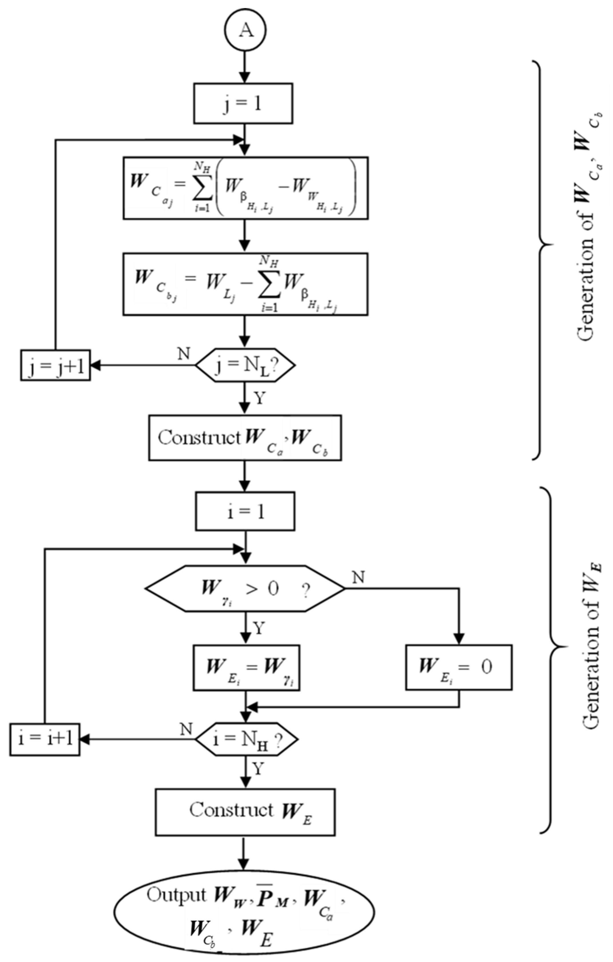
3. Synthesis Strategy
4. Thermodynamic-Model-Guided WEN Synthesis
4.1. Placement of Work Exchangers
4.2. Placement of Compressors and Expanders
5. Heat Integration with a WEN Design
6. WEN Design Modification after Heat Integration
7. Case Studies
7.1. Case 1—HIWEN Synthesis with Detailed Steps
7.2. Case 2—HIWEN Synthesis with Comprehensive Cost Comparison
8. Concluding Remarks
Author Contributions
Funding
Data Availability Statement
Conflicts of Interest
Nomenclature
| NH | the number of high-pressure streams |
| NL | the number of low-pressure streams |
| the matrix containing all of the identified pressure intervals between all of the pairs of high-pressure and low-pressure streams | |
| the source pressure of the high-pressure stream | |
| the target pressure of the high-pressure stream | |
| the source pressure of the low-pressure stream | |
| the target pressure of the low-pressure stream | |
| the matrix containing the pressure intervals of the work exchangers | |
| the lower bound of the pressure exchange interval for the low-pressure stream | |
| the upper bound of the pressure exchange interval for the low-pressure stream | |
| the vector of the streams’ source pressures | |
| the vector of the streams’ target pressures | |
| the vector of the streams’ inlet temperatures of a work exchanger network | |
| the vector of the streams’ outlet temperatures of a work exchanger network | |
| the vector of the streams’ source temperatures | |
| the vector of the streams’ target temperatures | |
| the vector containing the compression needed from external sources | |
| the vector containing the expansion needed from external sources | |
| the vector of the mechanical energy that can be provided by high-pressure streams | |
| the vector of the mechanical energy required by low-pressure streams | |
| the maximum amount of recoverable mechanical energy | |
| the matrix containing the workloads of the work exchangers | |
| the matrix storing all of the calculated energy transfer data | |
| the vector containing information about whether each individual high-pressure stream can provide sufficient mechanical energy to low-pressure streams | |
| ΔPmin | the minimum driving pressure differential |
| ΔTmin | the minimum driving temperature differential |
References
- Energetics Inc. Manufacturing Energy and Carbon Footprint. Prepared for the U.S. Department of Energy, Advanced Manufacturing Office; Energetics Inc.: Washington, DC, USA, 2014. [Google Scholar]
- Huang, Y.L.; Fan, L.T. Analysis of a work exchanger network. Ind. Eng. Chem. Res. 1996, 35, 3528–3538. [Google Scholar] [CrossRef]
- Deng, J.Q.; Shi, J.Q.; Zhang, Z.X.; Feng, X.A. Thermodynamic analysis on work transfer process of two gas streams. Ind. Eng. Chem. Res. 2010, 49, 12496–12502. [Google Scholar] [CrossRef]
- Chen, H.; Feng, X. Graphical approach for targeting work exchange networks. World Acad. Sci. Enginerring Technol. 2012, 6, 977–981. [Google Scholar]
- Liu, G.L.; Zhou, H.; Shen, R.J.; Feng, X. A graphical method for integrating work exchange network. Appl. Energy 2014, 114, 588–599. [Google Scholar] [CrossRef]
- Razib, M.S.; Hasan, M.M.F.; Karimi, I.A. Preliminary synthesis of work exchange networks. Comput. Chem. Eng. 2012, 37, 262–277. [Google Scholar] [CrossRef]
- Onishi, V.C.; Ravagnani, M.; Caballero, J.A. Simultaneous synthesis of work exchange networks with heat integration. Chem. Eng. Sci. 2014, 112, 87–107. [Google Scholar] [CrossRef]
- Huang, K.; Karimi, I. Work-heat exchanger network synthesis (WHENS). Energy 2016, 113, 1006–1017. [Google Scholar] [CrossRef]
- Du, J.; Zhuang, Y.; Liu, L.L.; Li, J.L.; Fan, J.; Meng, Q.W. Synthesis of indirect work exchanger network based on transhipment model. Comput. Aided Chem. Eng. 2015, 37, 1139–1144. [Google Scholar]
- Amini-Rankouhi, A.; Huang, Y. Mechanical energy recovery through work exchanger network integration: Challenges and opportunities. Comput. Aided Chem. Eng. 2018, 44, 409–414. [Google Scholar]
- Deng, J.Q.; Cao, Z.; Zhang, D.B.; Feng, X. Integration of energy recovery network including recycling residual pressure energy with pinch technology. Chin. J. Chem. Eng. 2017, 25, 453–462. [Google Scholar] [CrossRef]
- Fu, C.; Gundersen, T. Heat, and work integration: Fundamental insights and applications to carbon dioxide capture processes. Energy Convers. Manag. 2016, 121, 36–48. [Google Scholar] [CrossRef]
- Yu, H.; Gendersen, T. Review of work exchange networks (WENs) and work and heat exchange networks (WHENs). Chem. Eng. Trans. 2017, 61, 1345–1356. [Google Scholar]
- Yu, H.; Fu, C.; Vikse, M.; He, C.; Gundersen, T. Identifying optimal thermodynamic paths in work and heat exchange network synthesis. AIChE J. 2018, 65, 549–561. [Google Scholar] [CrossRef]
- Yu, H.; Vikse, M.; Anantharaman, R.; Gundersen, T. Model reformulations for work and heat exchange network (WHEN) synthesis problems. Comput. Chem. Eng. 2019, 125, 89–97. [Google Scholar] [CrossRef]
- Hamedi, H.; Karimi, I.; Gundersen, T. Simulation-based approach for integrating work within heat exchange networks for sub-ambient processes. Energy Convers. Manag. 2020, 203, 112276. [Google Scholar] [CrossRef]
- Huang, Y.; Zhuang, Y.; Zhuang, L.; Du, J. Synthesis of Work-integrated Heat Exchanger Networks Coupled with Organic Rankine Cycles. Chem. Eng. Trans. 2023, 103, 139–144. [Google Scholar]
- Pavão, L.; Costa, C.; Ravagnani, M. A new framework for work and heat exchange network synthesis and optimization. Energy Convers. Manag. 2019, 183, 617–632. [Google Scholar] [CrossRef]
- Pavão, L.; Mirandaa, C.B.; Caballerob, J.A.; Ravagnani, M.; Costa, C. Multiperiod work and heat integration. Energy Convers. Manag. 2021, 227, 113587. [Google Scholar] [CrossRef]
- Santos, L.; Costa, C.; Caballero, J.; Ravagnani, M. Synthesis and optimization of work and heat exchange networks using an MINLP model with a reduced number of decision variables. Appl. Energy 2020, 262, 114441. [Google Scholar] [CrossRef]
- Santos, L.; Costa, C.; Caballero, J.; Ravagnani, M. MINLP model for work and heat exchange networks synthesis considering unclassified streams. Comput. Aided Chem. Eng. 2022, 51, 793–798. [Google Scholar]
- Zhuang, Y.; Zhang, L.; Liu, L.; Du, J.; Shen, S. An upgraded superstructure-based model for simultaneous synthesis of direct work and heat exchanger networks. Chem. Eng. Res. Des. 2020, 159, 377–394. [Google Scholar] [CrossRef]
- Ibric, N.; Fu, C.; Gundersen, T. Simultaneous optimization of work and heat exchange networks. Energies 2024, 17, 1753. [Google Scholar] [CrossRef]
- Amini-Rankouhi, A.; Huang, Y. Prediction of maximum recoverable mechanical energy via work integration: A Thermodynamic Modeling and Analysis Approach. AIChE J. 2017, 63, 4814–4826. [Google Scholar] [CrossRef]
- Amini-Rankouhi, A.; Huang, Y. Modeling and simulation of a piston-type work exchanger for mechanical energy recovery. Ind. Eng. Chem. Res. 2019, 58, 18292–18300. [Google Scholar] [CrossRef]
- Walas, S.M. Chemical Process Equipment—Selection and Design. In Butterman-Heinemam Series; Gulf Professional Publishing: Houston, TX, USA, 1990. [Google Scholar]
- Yee, T.; Grossman, I. Simultaneous optimization models for heat integration—II. Heat exchanger network synthesis. Comput. Chem. Eng. 1990, 14, 1165–1184. [Google Scholar] [CrossRef]
- Linnhoff, B. Pinch analysis—A state-of-the-art overview. Chem. Eng. Res. Des. 1993, 71, 503–522. [Google Scholar]


| Stream No. | Supply Pressure (Ps, kPa) | Target Pressure (Pt, kPa) | Flowrate (kg/s) | Source Temperature (Ts, K) | Target Temperature (Tt, K) | Heat Capacity (CP, kJ/kg·K) |
|---|---|---|---|---|---|---|
| H1 | 850 | 100 | 3 | 600 | 430 | 1.432 |
| H2 | 960 | 160 | 5 | 580 | 300 | 0.982 |
| H3 | 800 | 300 | 2 | 960 | 300 | 1.046 |
| L1 | 100 | 510 | 3 | 300 | 700 | 1.432 |
| L2 | 100 | 850 | 3 | 300 | 600 | 1.432 |
| Parameter | Placement of the HEN | |
|---|---|---|
| Before WEN | After WEN | |
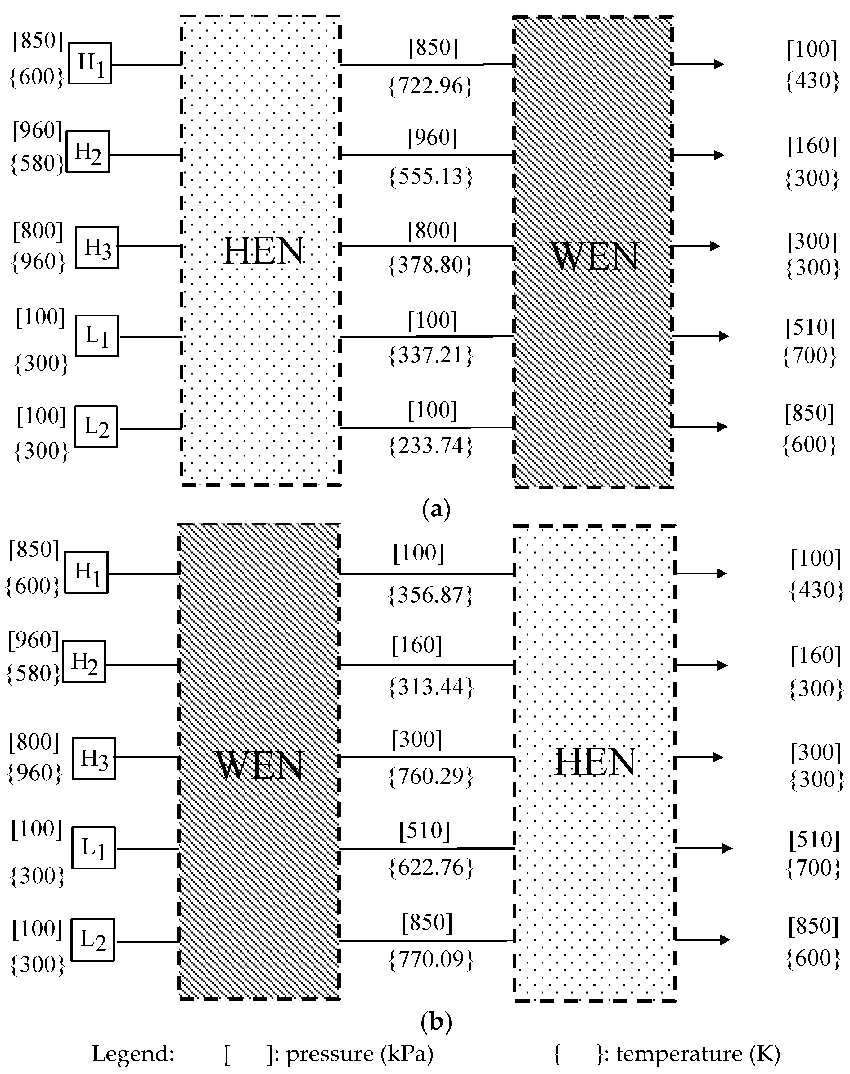
| Mech. energy recovery by WEs (kW) | 1,700.04 | 1,777.97 |
| External compression power (kW) | 1,431.98 | 1,628.13 |
| External expansion power (kW) | 976.04 | 993.13 |
| Thermal energy recovery by HEs (kW) | 688.07 | 645.95 |
| External cooling (kW) | 934.54 | 1,113.14 |
| Operating cost (k$/year) | 1,382 | 1,572 |
| Celec = 0.12 $/kWh; Csteam = 0.035 $/kWh; CCW = 0.001 kWh; Operational time = 8000 h/yr | ||
| Work Transfer Units and Symbols | Stream(s) | Pressure Interval of the H Stream | Pressure Interval of the L Stream | Workload (kW) | |
|---|---|---|---|---|---|
| Work Exchanger | W1 | H1/L1 | [850, 100] | [170, 230] | 266.69 |
| W2 | H1/L2 | [850, 100] | [170, 230] | 180.68 | |
| W3 | H2/L1 | [960, 160] | [230, 510] | 902.93 | |
| W4 | H2/L2 | [960, 160] | [610, 850] | 1,128.36 | |
| Compressor | C1 | L2 | [230, 610] | 778.52 | |
| C2 | L1 | [170, 230] | 389.04 | ||
| C3 | L2 | [170, 230] | 264.42 | ||
| Expander | E1 | H1 | [100, 850] | 811.18 | |
| E2 | H3 | [300, 800] | 164.86 | ||
| Design | This Work | Razib et al. [6] |
|---|---|---|
| Mech. energy exchange (kW) | 2,479 | 1,573 |
| Thermal energy exchange (kW) | 688 | - |
| Compression utility (kW) | 653 | 875 |
| Expansion utility (kW) | 198 | 1,415 |
| Heating utility (kW) | 80 | 688 |
| Cooling utility (kW) | 935 | 1,619 |
| No. of WEs | 5 piston-type (3 Vessel) WEs | 4 SSTC compressors plus 3 SSTC turbines |
| No. of HEs | 2 | - |
| No. of HT and CL | 4 | 11 |
| No. of compressors | 2 | 2 |
| No. of expanders/valves | 2 | 2 |
| CAPEX (k$/yr) | 1,440 | 1,253 |
| OPEX (k$/yr) | 657 | 2,404 |
| TAC (k$/yr) | 2,097 | 3,657 |
| Stream No. | Source Pressure (Ps, kPa) | Target Pressure (Pt, kPa) | Flowrate (kg/s) | Source Temperature (Ts, K) | Target Temperature (Tt, K) | Heat Capacity (CP, kJ/kg·K) |
|---|---|---|---|---|---|---|
| H1 | 900 | 100 | 15 | 350 | 350 | 2.454 |
| H2 | 850 | 150 | 15 | 350 | 350 | 0.982 |
| H3 | 700 | 200 | 15 | 400 | 400 | 1.432 |
| L1 | 100 | 700 | 18 | 390 | 390 | 1.432 |
| L2 | 100 | 900 | 15 | 420 | 420 | 2.454 |
| Statistic | Placement of the HEN | |
|---|---|---|
| Before WEN | After WEN | |
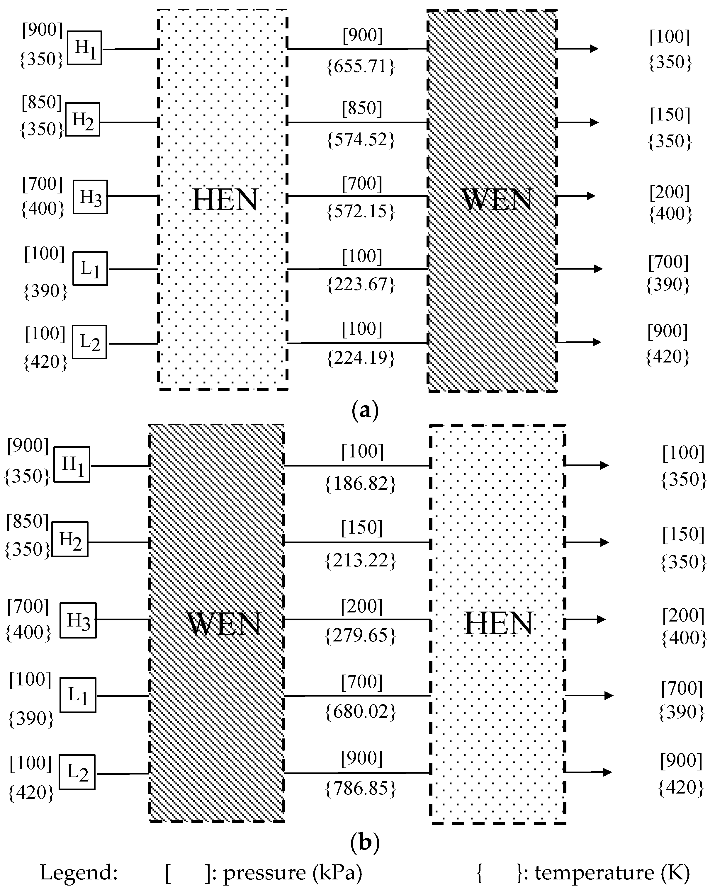
| Mech. Energy Recovery by WEs (kW) | 8,846.94 | 6,006.59 |
| External Compressor Energy (kW) | 2,648.29 | 14,972.56 |
| External Expander Energy (kW) | 9,410.97 | 4,599.90 |
| Thermal Energy Recovery by HEs (kW) | 2,908.20 | 10,606.54 |
| External Heater Energy (kW) | 15,349.71 | - |
| External Cooler Energy (kW) | 8,587.03 | 10,372.76 |
| OPEX (k$/year) | 6,909 | 14,457 |
| Celec = 0.12 $/kWh; Csteam = 0.035 $/kWh; CCW = 0.001 kWh; Operational time = 8000 h/yr | ||
| Process Units | Size Factor | CAPEX ($/Year) | OPEX ($/Year) | |
|---|---|---|---|---|
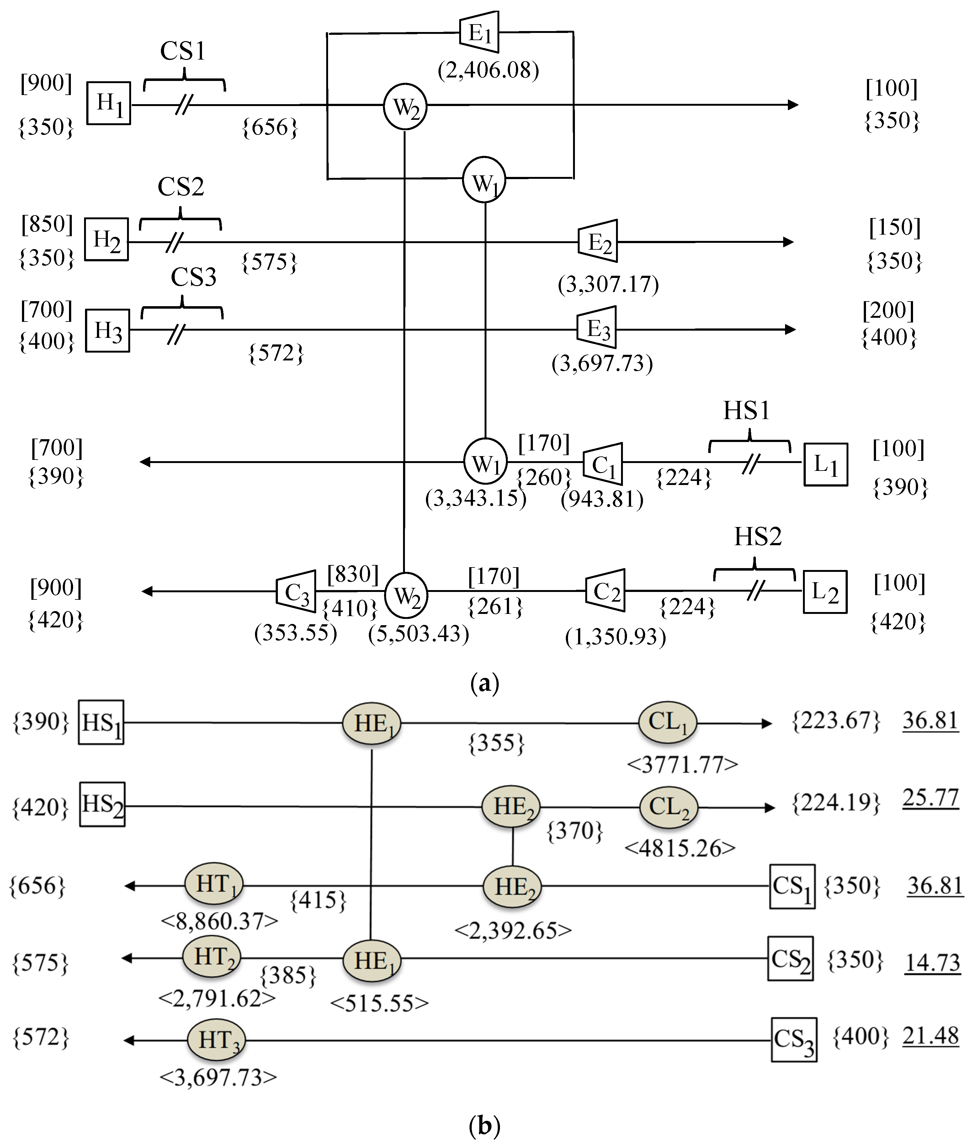
| Heat exchanger | HE1 | A = 9570 m2 | 290,118 | - |
| HE2 | A = 952 m2 | 31,554 | - | |
| Heater | HT1 | A = 734 m2 | 118,226 | 2,480,904 |
| HT2 | A = 182 m2 | 76,816 | 781,654 | |
| HT3 | A = 245 m2 | 25,021 | 1,035,364 | |
| Cooler | CL1 | A = 3841 m2 | 8469 | 38,522 |
| CL2 | A = 2461 m2 | 10,351 | 30,174 | |
| Compressor | C1 | F = 25.77 kW/k | 275,776 | 906,058 |
| C2 | F = 36.81 kW/k | 286,810 | 339,408 | |
| C3 | F = 36.81 kW/k | 286,810 | 1,296,893 | |
| Expander | E1 | F = 7.87 kW/k | 207,871 | - |
| E2 | F = 14.73 kW/k | 214,730 | - | |
| E3 | F = 21.48 kW/k | 221,480 | - | |
| Work exchanger | W1 | S = 20 L (10 vessels) | 351,993 | - |
| W2 | S = 20 L (10 vessels) | 351,993 | - | |
| Total | 2,758,018 | 6,908,976 | ||
| Design | This Work | Onishi et al. [7] | Huang and Karimi [8] |
|---|---|---|---|
| Mech. energy exchange (kW) | 8,847 | 10,474 | 11,579 |
| Thermal energy exchange (kW) | 2,908 | 8,794 | 15,920 |
| Compression utility (kW) | 2,648 | 8,840 | 7,734 |
| Expansion utility (kW) | 9,411 | - | - |
| Heating utility (kW) | 15,349 | 1,680 | 5,276 |
| Cooling utility (kW) | 8,587 | 10,520 | 13,010 |
| No. of WEs | 2 piston-type WEs | 3 SSTC compressors plus 3 SSTC turbines | 3 SSTC compressors plus 3 SSTC turbines |
| No. of HEs | 2 | 8 | 6 |
| No. of HT and CL | 5 | 5 | 9 |
| No. of compressors | 3 | 2 | 1 |
| No. of expanders/valves | 3 | 1 | - |
| CAPEX (k$/yr) | 2,758 | - | 1,180 |
| OPEX (k$/yr) | 6,909 | - | 9,006 |
| TAC (k$/yr) | 9,667 | 10,502 | 10,187 |
Disclaimer/Publisher’s Note: The statements, opinions and data contained in all publications are solely those of the individual author(s) and contributor(s) and not of MDPI and/or the editor(s). MDPI and/or the editor(s) disclaim responsibility for any injury to people or property resulting from any ideas, methods, instructions or products referred to in the content. |
© 2024 by the authors. Licensee MDPI, Basel, Switzerland. This article is an open access article distributed under the terms and conditions of the Creative Commons Attribution (CC BY) license (https://creativecommons.org/licenses/by/4.0/).
Share and Cite
Amini-Rankouhi, A.; Siddiqui, A.; Huang, Y. Thermodynamic Model-Based Synthesis of Heat-Integrated Work Exchanger Networks. Processes 2024, 12, 2293. https://doi.org/10.3390/pr12102293
Amini-Rankouhi A, Siddiqui A, Huang Y. Thermodynamic Model-Based Synthesis of Heat-Integrated Work Exchanger Networks. Processes. 2024; 12(10):2293. https://doi.org/10.3390/pr12102293
Chicago/Turabian StyleAmini-Rankouhi, Aida, Abdurrafay Siddiqui, and Yinlun Huang. 2024. "Thermodynamic Model-Based Synthesis of Heat-Integrated Work Exchanger Networks" Processes 12, no. 10: 2293. https://doi.org/10.3390/pr12102293
APA StyleAmini-Rankouhi, A., Siddiqui, A., & Huang, Y. (2024). Thermodynamic Model-Based Synthesis of Heat-Integrated Work Exchanger Networks. Processes, 12(10), 2293. https://doi.org/10.3390/pr12102293


