Abstract
Heat integration has been widely and successfully practiced for recovering thermal energy in process plants for decades. It is usually implemented through synthesizing heat exchanger networks (HENs). It is recognized that mechanical energy, another form of energy that involves pressure-driven transport of compressible fluids, can be recovered through synthesizing work exchanger networks (WENs). One type of WEN employs piston-type work exchangers, which demonstrates techno-economic attractiveness. A thermodynamic-model-based energy recovery targeting method was developed to predict the maximum amount of mechanical energy feasibly recoverable by piston-type work exchangers prior to WEN configuration generation. In this work, a heat-integrated WEN synthesis methodology embedded by the thermodynamic model is introduced, by which the maximum mechanical energy, together with thermal energy, can be cost-effectively recovered. The methodology is systematic and general, and its efficacy is demonstrated through two case studies that highlight how the proposed methodology leads to designs simpler than those reported by other researchers while also having a lower total annualized cost (TAC).
1. Introduction
Continuous improvement of process sustainability is a significant endeavor for the industry, largely due to natural resource depletion, environmental pressures, and global competition. A key indicator of process sustainability is energy efficiency. Over the past few decades, the process industry has demonstrated great success in thermal energy recovery, frequently through the incorporation of cost-effective heat exchanger networks (HENs). In contrast, mechanical energy recovery, while having a large scope in industrial settings with about a 30% mechanical energy loss in production [1], has not drawn sufficient attention.
From a thermodynamic point of view, heat flow, for which temperature is the state variable, can be holistically controlled to ensure thermal energy efficiency. Workflow, on the other hand, for which pressure is the state variable, is yet to be fully characterized so that opportunities for recovering mechanical energy can be thoroughly identified. In process plants, many process streams need to be pressurized to different levels, which require work for compression, while many others should be depressurized, also to different levels, which produce work through expansion. This provides opportunities for work exchange among process streams for mechanical energy recovery. One of the technical approaches is to design work exchanger networks (WENs) for process plants. The concept of WEN synthesis was first introduced by Huang and Fan [2]. In their work, work exchangers (WEs) were piston-type devices that can be called direct WEs, and a detailed thermodynamic analysis of work integration was provided.
WEN synthesis did not catch sufficient attention initially until around 2010. Deng et al. conducted a basic thermodynamic analysis on gas–gas work exchange using direct WEs [3]. Chen and Feng described a graphical method for the design of a WEN for ammonia synthesis [4]. Liu et al. proposed a method using the pressure–work diagram that was initially introduced by Huang and Fan [5].
Razib et al. proposed the use of two-stream single-shaft-turbine-compressor (SSTC) units, a type of indirect work exchange unit, to design a WEN [6]. A superstructure-based modeling method was introduced, and a network was designed using a mixed-integer nonlinear programming (MINLP) technique. Onishi et al. described a new MINLP optimization model for WEN synthesis with hypothetic heat integration for optimal pressure recovery of gaseous processes that also uses SSTC units [7]. Huang and Karimi included a HEN in a WEN system and minimized total annualized cost (TAC) [8]. Meanwhile, Du et al. presented a transshipment model for WEN synthesis, where SSTC units were used under isothermal conditions [9]. The above studies have made significant strides in the advancement of WEN synthesis; however, many of them use SSTC units or indirect WEs. It is noted from Amini-Rankouhi and Huang’s study that indirect WEs may greatly limit mechanical energy recovery [10].
In a study by Deng et al., both direct and indirect WEs were analyzed alongside heat integration [11]. A pinch analysis technique was used for the WEN design. However, the efficiency of mechanical energy recovery could not be guaranteed. Gundersen and associates discussed the importance of work integration alongside heat integration and analyzed the effect of compressor and expander placement on overall energy recovery in HENs [12,13,14,15]. They used these ideas to introduce the work–heat exchange network (WHEN) synthesis problem. This type of synthesis problem was also studied by Hamedi et al. [16], Huang et al. [17], Pavão et al. [18,19], Santos et al. [20,21], and Zhuang et al. [22], who used different optimization or meta-heuristic techniques in solution derivation. Very recently, Ibric et al. described an MINLP-based solution method for integrating a HEN into a WEN that was composed of compressors and expanders only [23]. These proposed methods, while effective at mechanical energy recovery, only use compressors and expanders. They do not make use of WEs for integration and, as such, do not fall under the scope of this study. The piston-type work exchanger is a cylindrical device for direct pressure exchange between a high-pressure stream on one side of the piston and a low-pressure stream on the other side of the piston. It is structurally and operationally different from the single-shaft-turbine-compressor (SSTC), which has a single shaft, with part of the turbine’s output driving the compressor. Thus, the thermodynamic modeling and analysis and the model-based synthesis methodology proposed in this work cannot be directly applied to the SSTC-based work exchanger network design. On the other hand, the introduction of piston-type work exchangers is intended to reduce the number of compressors, which are generally more expensive.
As is clear from the extensive work conducted in the area, researchers have made substantial progress on the subject of WENs. However, there is still much room for advancement, especially for the design of WENs using piston-type direct WEs. Amini-Rankouhi and Huang introduced a thermodynamic analysis method for the evaluation of the maximum amount of feasibly recoverable mechanical energy by this type of WEN prior to flowsheet generation [24]. It shows that the preset mechanical energy recovery target is theoretically achievable and the energy efficiency of such a WEN is higher than in previous studies. The robustness of the proposed thermodynamic method allowed it to be used by the authors in this work as well. A further study by this group also reported a low capital cost feature of this type of WEN, as compared with the WENs that use other types of units [10]. Additionally, a comprehensive study on the design of direct WEs was conducted, and a detailed dynamic analysis of such a unit type in operation was performed [25].
WENs are highly complex because of the effects of pressurization and depressurization on the temperature of process streams. This, coupled with the fact that stream temperatures entering and leaving a WEN are usually determined by the operational requirements of the upstream and downstream process units, necessitates the incorporation of heat integration in the WEN design. In this work, we introduce a thermodynamic-model-based synthesis methodology, building upon the previous work introduced by Amini-Rankouhi and Huang [10,24], to develop a heat-integrated work exchanger network (HIWEN).
This paper is organized as follows: We first define the HIWEN synthesis task and summarize the thermodynamic-model-based method for the prediction of the maximum mechanical energy recovery prior to WEN synthesis. We then describe a synthesis strategy for HIWEN development. After that, we introduce a systematic synthesis methodology for stepwise HIWEN flowsheet development. Two case studies are then illustrated to detail the application of the synthesis methodology. The methodological efficacy is finally discussed, and future work is presented.
2. Synthesis Task and Prediction of Maximum Mechanical Energy Recovery
The WEN synthesis task can be described as follows: Given a set of high-pressure and low-pressure process streams, whose source and target pressures and temperatures, flowrates, heat capacities, and phases are specified, design a work exchanger network (WEN) using piston-type direct work exchangers (referred to simply as WEs in this paper), which maximizes energy recovery while also presenting the lowest possible cost for that scenario. The minimum driving pressure differential (ΔPmin) in each WE is pre-defined, and compressors and expanders are available to provide “external” power for pressurization and depressurization of process streams as needed.
To address such a problem statement, the maximum amount of mechanical energy recoverable by a WEN should be determined prior to network design. To do this, Amini-Rankouhi and Huang developed a rigorous and general thermodynamic modeling and analysis method to accurately identify the maximum amount of recoverable mechanical energy of any process plant [24]. The following is a summarized three-step procedure that briefly describes the method; for detailed formula derivations, please read Amini-Rankouhi and Huang [24].
(1) Identify the pressure intervals of the low-pressure streams (denoted as L streams) for pressurization by the high-pressure streams (denoted as H streams). Since WEN synthesis involves a series of stream matchings through which a certain amount of mechanical energy is transferred from each pair of H streams and L streams, it is necessary to identify the pressure intervals for the set of H streams and L streams. The formulations for this task are listed in boxes No. 1 and 2 in Figure 1, where matrix contains all of the identified pressure intervals between all of the pairs of H and L streams. Alongside the derivation of matrix , two vectors should also be determined based on the given stream data: (the mechanical energy that can be provided by H streams) and (the mechanical energy required by L streams).
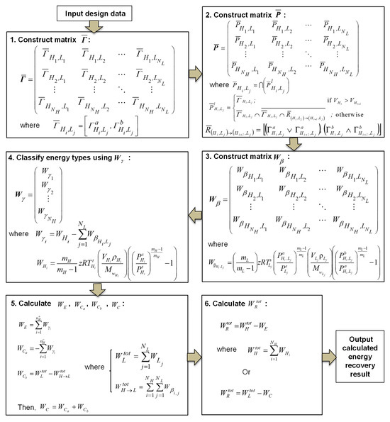
Figure 1.
Systematic procedure for the evaluation of maximum recoverable mechanical energy.
(2) Evaluate the mechanical energy transfer from H streams to L streams. By using the pressure interval information contained in matrix , the mechanical energy transferrable from each pair of H and L streams can be calculated using the formulas listed in boxes No. 3 and 4 of Figure 1. Matrix Wβ should be created to store all the calculated energy transfer data, and vector should be created to contain information about whether each individual H stream can provide sufficient mechanical energy to the L streams if they are matched.
(3) Determine the minimum amount of external energy required and the maximum amount of recoverable mechanical energy. This task is accomplished in two steps. The first step is to estimate the minimum amount of external energy required. The formulas listed in box No. 5 are for the calculation of and , which are the compression and expansion power needed from external sources, respectively. With these derived, the maximum amount of recoverable mechanical energy, , can be determined using either of the two formulas listed in box No. 6 of Figure 1.
3. Synthesis Strategy
As discussed above, meeting the temperature specifications for upstream and downstream processes requires the incorporation of heat integration into the design. This causes the WEN design to be coupled with an additional task: the integration of a HEN into a WEN, thereby rendering a heat-integrated WEN (HIWEN). To do this, two strategies for heat integration are proposed: either the integration is synthesized after the WEN synthesis or during the synthesis. Of the two strategies, synthesizing heat integration during WEN synthesis is not preferable. Such an integration strategy makes the whole synthesis not only very complex but, more importantly, also not efficient for thermal energy recovery. Alongside this, the dynamic characteristics and operational features of piston-type WEs explained by Amini-Rankouhi and Huang may bring additional operational challenges if a heat transfer unit is placed between two WEs [10]. Thus, it is more appropriate to synthesize a WEN first and use the resulting temperature profiles to define a heat integration problem. The simultaneous optimization of both networks is a direction that will be considered in the future. Thus, based on the identified hot and cold process streams of the synthesized WEN, a HEN can be developed. The resulting HEN can then be integrated into the WEN to generate a HIWEN that should result in the maximum recovery of mechanical and thermal energies at the lowest total annualized cost.
4. Thermodynamic-Model-Guided WEN Synthesis
For a synthesis problem involving NH high-pressure (H) streams and NL low-pressure (L) streams, the maximum amount of recoverable energy by a WEN can be determined by the methodology developed by Amini-Rankouhi and Huang prior to network design [24]. The main tasks of the synthesis can be accomplished using the thermodynamic models to determine: (1) the placement of the minimum number of WEs between a set of H streams (NH) and a set of L streams (NL) such that the maximum amount of mechanical energy is recovered, and (2) the placement of the minimum number of compressors and expanders such that the least amount of external energy is consumed.
4.1. Placement of Work Exchangers
Determining the optimal placement of WEs requires the selection of stream pairs within the proper pressure intervals for recovering the maximum amount of mechanical energy. To select stream pairs, two matrices, and , are used, referring to the workload and pressure interval of each WE match, respectively. Figure 2 shows how matrices and are derived.
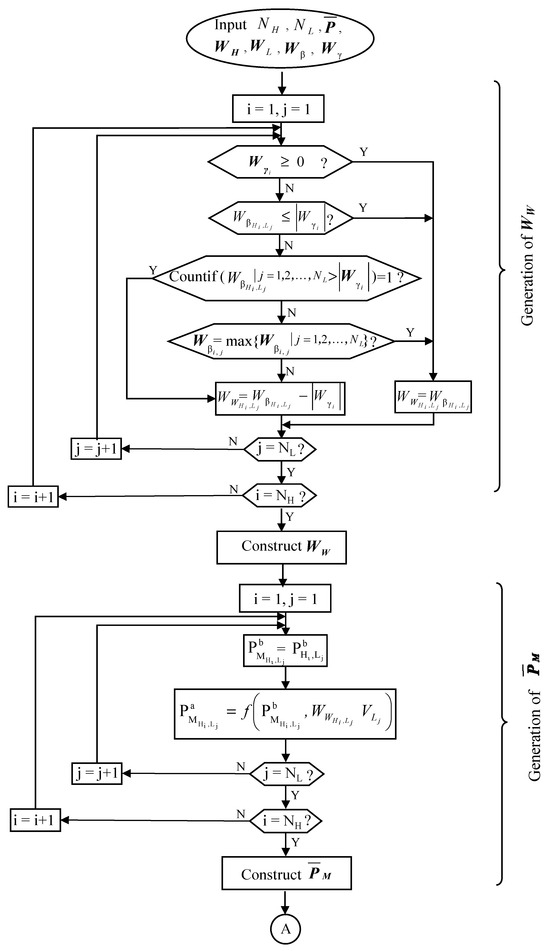
Figure 2.
Generation of and .
Detailed steps for matrix construction are described below.
Step 1. Determination of pairs of H streams and L streams for matching and the amount of mechanical energy to recover in each WE. This can be realized by constructing matrix below.
where is the workload of the WE that is used to match the Hi stream with the Lj stream.
To determine the element values of the matrix, the information contained in the following matrices and vectors is used: (), (), (), (), and (). Each of these matrices and vectors were derived when predicting the maximum recoverable mechanical energy, and as a result, their derivations are not detailed here. For more detailed explanations, refer to Figure 1 or Amini-Rankouhi and Huang’s previous work [24].
The procedure for deriving matrix is shown in Figure 2. Note that matrix contains the amount of mechanical energy that can be feasibly transferred from each H stream to each L stream. However, the amount of energy that can be provided by an H stream can be either higher, equal, or lower than that of an L stream based on the data in vector . Therefore, to generate matrix , matrix and vector need to be used to find the most appropriate locations for placing WEs. Any positive term in vector indicates that the relevant H stream can provide sufficient mechanical energy to the L streams assigned to it. As shown in Figure 2, for the situation where has a positive value of the i-th H stream or an absolute value less than a WE should be placed with a workload equal to . If has a negative value and its absolute value is higher than , a WE should also be placed, but the workload should be unless is the largest number in the j-th column of .
Step 2. Determination of the pressure intervals of the stream pairs where work exchangers are placed. This can be realized by constructing matrix below.
where
Note that gives the pressure interval of low-pressure stream Lj such that within this interval it can receive mechanical energy from high-pressure stream Hi. The high-pressure stream is also within its own given pressure range of . Once matrix is completed, each element in it, as long as it is not a null interval (i.e., [0, 0]), should be indicative of one WE to be placed in the interval of for the Hi stream and in the interval of for the Lj stream. The energy exchange between the two streams is equal to , which was calculated in Step 1.
Note that the amount of mechanical energy that needs to be removed from the Hi stream in the pressure range of may be transferrable to more than one low-pressure stream. In this case, stream Hi can be split into two or more branches.
The interval values of element are determined using the following equations. The upper bound is set to be the upper bound of the interval , i.e.,
and the lower bound is to be calculated depending on the operating condition below:
In the above formula, parameter k is a ratio of the heat capacity at constant pressure and volume (i.e., ), and parameter m is related to parameter k (i.e., ), where is the polytropic efficiency. If reaches 100% (i.e., no friction), then parameters k and m are equal. Hence, . For more detailed information about formula derivation, see Walas and Liu et al. [5,26].
For cases where a HEN will be located before the WEN, the formulation shown in Equation (5) will be slightly changed. This will be discussed later.
4.2. Placement of Compressors and Expanders
For any L stream, if its outlet pressure when leaving a WEN after receiving mechanical energy from one or more H streams still has not reached its target pressure, then one or more compressors will be needed. The location(s) and power(s) of such compressor(s) can be determined by constructing two vectors: and . Figure 3 shows a procedure for generating these vectors.
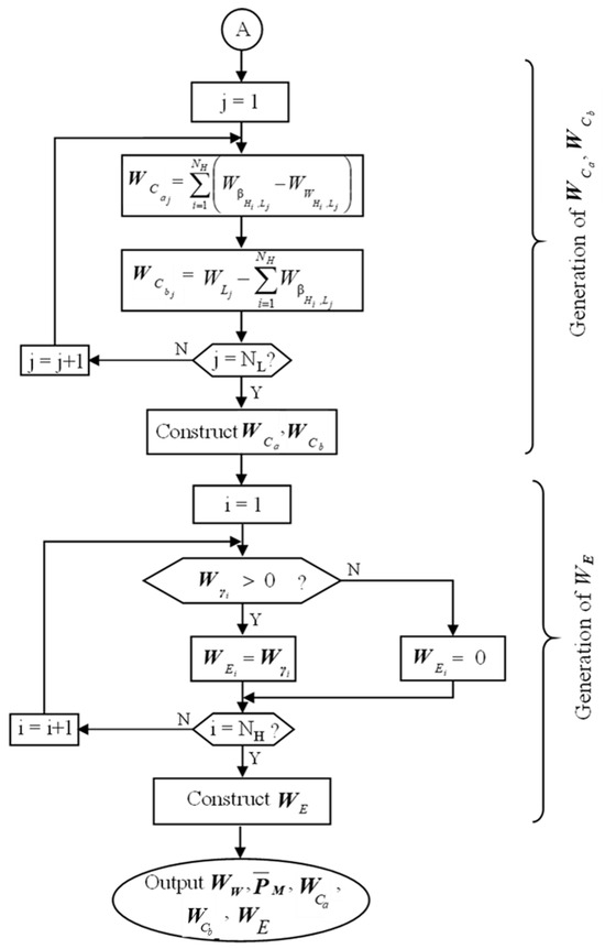
Figure 3.
Generation of , , and .
Vector is of the following structure:
where
Note that is the amount of mechanical energy that can be feasibly transferred from the Hi stream to the Lj stream. However, this does not mean the energy needs to be fully transferred; it is possible that a certain amount of energy from the Hi stream may be transferred to some other low-pressure stream(s); is the amount of mechanical energy that the Lj stream has received from the Hi stream through a WE that matches this pair of streams. Thus, gives the power needed for a compressor to be placed on the Lj stream if its value is not zero.
It is possible that the Lj stream, even after having a compressor placed to raise its pressure, may still have not received all the necessary amount of compression in order to be pressurized to its target pressure (). For this reason, vector is introduced to identify the location(s) and the power(s) for additional compressor(s) for all L streams. Figure 3 shows how to generate this vector. A more detailed explanation is provided below:
where
Note that is the total amount of mechanical energy needed in order to raise the low-pressure stream’s source pressure () to its target pressure (). If it is still greater than the total amount of mechanical energy that can be feasibly transferred from all the high-pressure streams (i.e., ), then additional compressor(s) need to be placed.
It is possible that a high-pressure stream (Hi), after a feasible transfer of mechanical energy to one or more L streams, has an outlet pressure that is higher than its target pressure (). If this is the case, then an expander is needed. Thus, vector is introduced, which has the following structure:
where
Note that a positive value of means the amount of mechanical energy left in the Hi stream is unable to be feasibly transferred to any L streams. Under this situation, an expander is needed so that the Hi stream can reduce its pressure to its target pressure ().
5. Heat Integration with a WEN Design
The WEN synthesis methodology described in the last section is applicable to any design problem where stream target temperatures are not defined. However, in industrial applications, there are requirements for the temperatures of the streams leaving the WENs that are set by the downstream systems for their operations. In particular, Deng et al. suggested that more attention should be given to a WEN where streams are in the gas phase [3]. As such, processes with adiabatic conditions where the outlet temperatures of streams, after each stage of pressurization or depressurization, are different from the desired temperatures are of particular focus. These systems will require heating or cooling, and thus heat integration will have to be applied alongside work integration.
Heat integration is realized through synthesizing a cost-effective HEN. The HEN can be placed either before or after the WEN, as shown in Figure 4, where vectors and are the source and target pressures of all high-pressure and low-pressure streams, respectively, and vectors and are their source and target temperatures, respectively.
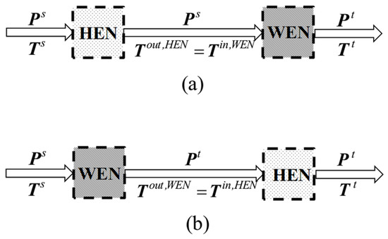
Figure 4.
Options for the placement of a HEN: (a) HEN located before WEN and (b) WEN located before HEN.
Note that the pressures of the streams entering and leaving the HEN are the same, as it is commonly assumed that the pressure drop of a stream through a heat transfer unit is negligible. However, the stream temperatures in the middle of the two networks, in Case (a) and Case (b), are different from either or . These stream temperatures are calculated as follows for each case:
Case (a)—the HEN is positioned before the WEN. As shown in Figure 4a, the inlet temperatures of each stream in the HEN are known, i.e., and . In addition, the outlet temperatures and pressures of the WEN are also known, i.e., , , , and Between the HEN and the WEN, and , as it is assumed that there is no pressure drop in any heat transfer unit. The values of (i.e., ) and (i.e., ) are unknown and can be calculated based on the given stream target temperatures (i.e., ). These temperatures can be calculated based on each stream’s target temperatures () and source and target pressures ( and , respectively), which are also known.
As an example, the i-th stream’s temperature when entering the WEN () can be calculated using the equation below, assuming it is under the polytropic (adiabatic frictional) condition.
Case (b)—the HEN is positioned after the WEN. As shown in Figure 4b, the only unknown parameters are the stream temperatures between the WEN and the HEN, which are (i.e., ) and (i.e., ). The outlet temperatures of the streams when leaving the WEN (i.e., ) can be calculated based on the given stream source temperatures (i.e., ). As an example, the i-th stream’s temperature when leaving the WEN () can be calculated using the equation below, again assuming a polytropic (adiabatic frictional) condition.
The above two formulas are applicable to both high-pressure and low-pressure streams.
After determining the streams’ temperatures in the middle of the two networks in either Case (a) or Case (b), the HEN design problems are fully defined, as is the WEN design problem. Figure 5 shows a procedure for selecting the location of the HEN based on an estimation of energy recovery and TAC.
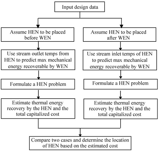
Figure 5.
Flowchart for the determination of a HEN location.
Note that in the estimation process, the prediction of the maximum recoverable mechanical energy by the WEN should be performed using the methodology developed by Amini-Rankouhi and Huang [24]. Thermal energy recovery alongside external heating and cooling can be developed by various matured methods, such as mixed-integer nonlinear programming (MILP)-based methods [27] or Pinch Analysis-based methods [28].
6. WEN Design Modification after Heat Integration
The synthesized WEN, when connected to the derived HEN, generates a heat-integrated WEN (i.e., HIWEN) that can recover both mechanical and thermal energies at the lowest possible cost. Note that there could be further opportunities to recover more mechanical energy in the integrated network because the temperatures and flowrates of some high-pressure and low-pressure streams may be adjustable within some small ranges. Thus, some compressor(s) and expander(s) in the WEN design may be replaceable by additional WE(s). Therefore, the derived HIWEN needs to be evaluated for an improvement opportunity. The following procedure can be followed to identify such an opportunity for further improvement of the energy recovery in the system:
Step 1. Identify the compressor on the L stream that consumes the highest external power in the flowsheet.
Step 2. Identify an expander on an H stream that can provide the mechanical energy required by the identified compressor. If no expander is left, then identify the next compressor and repeat Step 2; otherwise, go to Step 4.
Step 3. Check the matching feasibility using the thermodynamic models.
(a) If feasible, then determine the maximum amount of mechanical energy recoverable by a WE, which is to be used to replace the compressor and the expander. The relevant streams’ inlet and outlet pressures and temperatures should be calculated. This may result in a smaller compressor or expander and a heater or cooler to meet the process specifications. Whether this replacement is acceptable or not depends on the cost estimation. If acceptable, then modify the process.
(b) If infeasible, then identify another compressor on an L stream that consumes the next highest external power in the flowsheet and go to Step 2.
Step 4. Stop the process modification. The resultant HIWEN is the final design.
7. Case Studies
The synthesis methodology introduced in this work has been successfully used to solve a number of HIWEN design problems. In this section, two of them, selected from the open literature, are illustrated to show the robustness of the introduced methodology. For the work transfer units (piston-type WEs, compressors, and expanders), isentropic (adiabatic) conditions, reversibility, and 100% efficiency are assumed. Stream heat capacities are assumed to be constant, and pressure drops in heat transfer units (heat exchangers, heaters, and coolers) are assumed negligible.
7.1. Case 1—HIWEN Synthesis with Detailed Steps
The design problem reported by Razib et al. is selected for study [6]. In their work, single-shaft-turbine-compressor (SSTC) units are used as work exchangers. In this study, piston-type direct work exchangers are employed. This problem was analyzed in previous studies for predicting the maximum recoverable mechanical energy, and thus the prediction result in that study is adopted [24]. Table 1 lists the stream data for this synthesis problem, which has three high-pressure streams (H1 to H3) and two low-pressure streams (L1 and L2).

Table 1.
Process stream data for Case 1.
To implement the methodology introduced in this work, the WEN and the HEN design problems should be defined by following the steps listed in Figure 5. For the HEN, ΔTmin was defined as 10 K.
Option 1—HEN placed before the WEN. Taking streams H1 and L1 as an example, and are evaluated as follows:
and
where is the heat capacity and is the specific gas constant given by Razib et al. [6].
Figure 6a lists all the pressure and temperature data of the process streams for the WEN and HEN synthesis problems. As shown, for the HEN problem, there are three hot streams (H2, H3, and L2) and two cold streams (H1 and L1).
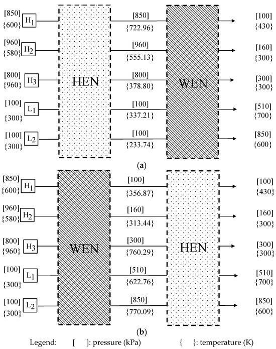
Figure 6.
(a) HEN located before the WEN design and (b) HEN located after the WEN design for Case 1.
At the same time, a WEN synthesis problem is completely defined, as shown in Figure 6a. The maximum recoverable mechanical energy of this problem can be predicted using the methodology by Amini-Rankouhi and Huang [24]. The three high-pressure streams (H1 to H3) listed in Table 1 and Figure 6a can provide a total of 2,676 kW of mechanical energy, while the two low-pressure streams (L1 and L2) also in Table 1 and Figure 6a require a total of 3,132.02 kW. However, the transferable mechanical energy from the high-pressure streams to the low-pressure streams is calculated as 1,700.04 kW. This accounts for 63.5% of the total mechanical energy of the three high-pressure streams and 54.3% of the total mechanical energy required by the two low-pressure streams.
For the HEN design problem, the hot streams (H2, H3, and L1) need to remove a total of 1,623 kW in different temperature ranges, while the cold streams (H1 and L2) require a total of 688 kW. By the Pinch Analysis method, the pinch point is located at 960 K for the hot streams and 950 K for the cold streams. This is a simple synthesis problem as all the streams are below the pinch temperature. The maximum amount of thermal energy recoverable is found to be 688 kW, and the minimum number of heat transfer units is 5. Note that a few design alternatives for the HEN design use the Pinch Analysis method. The one with the lowest TAC is chosen. It is also of note that because all the streams are below the pinch point, each derived HEN can recover the maximum amount of thermal energy while also using the minimum number of heat transfer units.
Option 2—HEN placed after the WEN. Taking streams H1 and L1 as an example, and are evaluated as follows:
and
Figure 6b lists all the pressure and temperature data of the process streams for the WEN and HEN synthesis problems. As shown, for the HEN problem, there are also three hot streams (H2, H3, and L2) and two cold streams (H1 and L1). Note that the temperature ranges of the streams in Figure 6b are very different from those in Figure 6a.
The WEN synthesis problem is also completely defined, as shown in Figure 6b. The maximum recoverable mechanical energy of this problem design can also be predicted using the methodology by Amini-Rankouhi and Huang [24]. The three high-pressure streams (H1 to H3) listed in Table 1 and Figure 6b can provide 2,771 kW of mechanical energy, and the two low-pressure streams (L1 and L2) require 3,406 kW. However, the transferable mechanical energy from the high-pressure streams to the low-pressure streams is calculated as 1,777.97 kW. This accounts for 64.15% of the total mechanical energy of the high-pressure streams and 52.2% of the total mechanical energy required by the low-pressure streams.
For the HEN design problem, the hot streams (H2, H3, and L2) need to remove a total of 1,759.84 kW in different temperature ranges, while the cold streams (H1 and L1) require a total of 646.25 kW. By the Pinch Analysis method, the pinch point is identified as 770.09 K for the hot streams and 760.09 K for the cold streams. This makes the design simple, as all the streams are below the pinch point.
The results of both options are summarized in Table 2. If comparing the operating costs of the two designs, the HEN should be placed before the WEN. These two networks can be designed separately.

Table 2.
Energy recovery and operating cost comparison of the HIWENs with a HEN placed before or after a WEN for Case 1.
WEN flowsheet development. The process stream data are provided in Table 1 and Figure 6a. The following matrices are calculated using the prediction methodology by Amini-Rankouhi and Huang, which is shown in Figure 1 [24]. For this design problem involving three high-pressure streams (H1 to H3) and two low-pressure streams (L1 and L2), matrix contains the identified pressure intervals between all of the pairs of high-pressure and low-pressure streams, which are as follows:
Vector contains the mechanical energy that can be provided by each of the three high-pressure streams; it is obtained as follows:
Vector lists the required mechanical energy of each of the two low-pressure streams; it is calculated as follows:
Matrix contains information about the transferrable mechanical energy between each pair of high-pressure and low-pressure streams. It is derived as follows:
Vector includes the data that show whether each individual high-pressure stream can provide mechanical energy to the low-pressure streams. It is calculated as follows:
Determination of the placement of work exchangers (WEs). WEs are to be placed by identifying pairs of streams for matching. Matrix shown below is designed to contain all the stream matching information.
The six elements in the matrix are derived as follows:
Since is a positive value (811.18 kW), the two elements related to high-pressure stream H1 can be readily obtained as follows:
Corresponding to stream H2, has a negative value (−778.52 kW), but its absolute value is smaller than (902.83 kW). Thus, we have the following:
As for , since has a negative value (−778.52 kW) and its absolute value is less than (1128.36 kW), we have the following:
Since is a positive value (164.86 kW), we have the following:
and
Thus, matrix can be obtained as follows:
As shown, four WEs need to be placed, and the workload of each exchanger is listed in the matrix.
Determination of the pressure intervals of the WEs placed. From the operational stability point of view, if two or more WEs are used to transfer mechanical energy from a high-pressure stream, it is better to split the high-pressure stream so that the WEs are operated in parallel. This strategy is used here to split both streams H1 and H2 that are to be matched with streams L1 and L2. The pressure intervals of the low-pressure streams are contained in matrix as follows:
The derivations of and are shown below.
Calculation of . This interval is derived from . According to Equation (4), the upper bounds of both intervals are the same, i.e.,
The lower bound is calculated as follows:
Thus,
Calculation of . This interval is derived from . According to Equation (4), the upper bounds of both intervals are the same, i.e.,
The lower bound is calculated in the same way as Equation (33).
Therefore,
The other four elements in matrix can be calculated using the same approach. The complete matrix is as follows:
Placement of the compressors. The amount of mechanical energy transferred from high-pressure streams H1 and H2 is insufficient for the low-pressure streams L1 and L2 to be pressurized to their target pressures. Thus, compressors are needed, which require the determination of the number of compressors, their powers, and placement locations. This task can be accomplished below.
Using Equations (6) and (7) and the data in Equations (23) and (32), vector is obtained as follows:
As shown above, one compressor, named C1, should be placed to pressurize stream L2 in the pressure range of [230, 610.40], and the power is 778.52 kW. This pressure interval is found by comparing the pressure intervals from the second columns and the second rows of matrices in Equation (18) and in Equation (38).
Matrix is derived below using Equations (8) and (9) and the data in Equations (20) and (21).
After comparing the pressure intervals in matrix in Equation (18) with the source and target pressures of each low-pressure stream from Table 1, it is determined that two compressors, named C2 and C3, should be placed. C2 is used to pressurize L1 in the pressure interval of [100, 170] with a workload of 389.04 kW, and C3 is used for L2 with a workload of 264.42 kW in the pressure interval of [100, 170].
Placement of the expanders. Note that the mechanical energy possessed by high-pressure stream H3 cannot be used to pressurize any low-pressure stream at this stage. Vector is derived below using Equations (10) and (11) and the data in Equation (22).
As shown, two expanders, named E1 and E2, are needed. E1 is for H1 with a workload of 811.18 kW in the pressure interval of [100, 850], and E2 is for H3 with a workload of 164.86 kW in the pressure interval of [300, 800].
Summary of the placement of the work transfer units and the process flowsheet. Table 3 summarizes the information derived above, which includes four work exchangers (W1 to W4), three compressors (C1 to C3), two expanders (E1 and E2), and the pressure intervals of the streams and their workloads. Figure 7a gives the derived flowsheet of the WEN.

Table 3.
Placement of work transfer units in the WEN for Case 1.
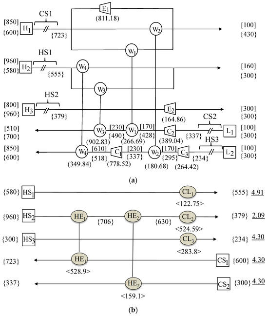
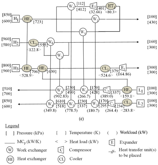
Figure 7.
Flowsheet of the heat-integrated work exchange network for Case 1: (a) the WEN, (b) the HEN, and (c) the HIWEN.
HEN design. It has been decided that the HEN is to be placed before the WEN. Figure 6a has listed the inlet and outlet temperatures of the three hot and two cold streams. These streams are marked in Figure 7a as well. They are hot streams named HS1, HS2, and HS3, which are the first part of high-pressure streams H2 and H3 and low-pressure stream L2, respectively, and cold streams named CS1 and CS2, which are the first part of high-pressure stream H1 and low-pressure stream L1, respectively. This is a simple synthesis problem, as all of the streams are below the pinch point. By using the Pinch Analysis method, an optimal flowsheet is obtained, which is shown in Figure 7b, where two heat exchangers (HE1 and HE2) and three coolers (CL1 to CL3) are employed to recover the maximum amount of thermal energy of 646.25 kW.
Design improvement. The HEN in Figure 7b should be integrated into the WEN in Figure 7a to generate a HIWEN. The design should be evaluated using the four-step method in Section 5 for possible design improvement. By executing Step 1, compressor C1 on stream L2 is identified. As shown in vector , the workload of the compressor is 778.52 kW in the pressure interval of [230, 610]. In Step 2, expander E1 on a branch of stream H1 is selected, which has a workload of 811.18 kW in the pressure interval of [850, 100]. In Step 3, it is confirmed that the mechanical energy of H1 is 778.52 kW and can be used to pressurize L2 by adding exchanger W5. In this way, compressor C1 is no longer needed, and expander E1 can be much smaller as the workload is reduced from 811.18 kW to 32.66 kW. With this design modification, the total mechanical energy recovery is improved by 45.8% (from 1,700 kW to 2,479 kW), and the external compression and expansion utility requirements are decreased, respectively, by 54% (from 1,432 kW to 653 kW) and 83% (976.04 kW to 164.86 kW). The TAC is also decreased from $2,964,000 to $2,097,000. In particular, the operating cost decreased by more than 52% from $1,382,000 to $657,000. A complete HIWEN flowsheet is shown in Figure 7c.
This HIWEN design was compared to the design by Razib et al. [6] and can be seen in Table 4. It is of note that the TAC reported in this study for the design made by Razib et al. is different from their report. This is because the method and assumptions for calculating the operating cost were changed to those used by the authors of this study in the interest of consistency. However, the capital cost calculations were not changed. Assumptions for capital cost can be found in Razib et al. [6]. As is shown in Table 4, the design by Razib et al. has a slightly lower capital cost, but the operating cost for the design proposed in this study is significantly less. In fact, the TAC decreased by more than 42% when compared to that of the optimal design proposed by Razib et al., showing clearly the efficacy of this design and the significant improvements it can make on proposed designs from the literature.

Table 4.
Performance comparison of HIWENs to different methods for Case 1.
7.2. Case 2—HIWEN Synthesis with Comprehensive Cost Comparison
The design problem studied by Onishi et al. [7] and Huang and Karimi [8] is selected for this case study, which makes a comprehensive cost comparison possible due to the data available in those studies. Both studies used single-shaft-turbine-compressor (SSTC) units, and the designs were obtained using mathematical programming techniques to achieve the lowest possible TAC. The data for the synthesis problem are summarized in Table 5.

Table 5.
Process stream data for Case 2.
HIWEN design. The same synthesis methodology used in Case 1 is used here. The network development steps are exactly followed. Thus, the calculation details are omitted here. Figure 8 shows two design options: (a) a HEN before the WEN and (b) a HEN after the WEN.
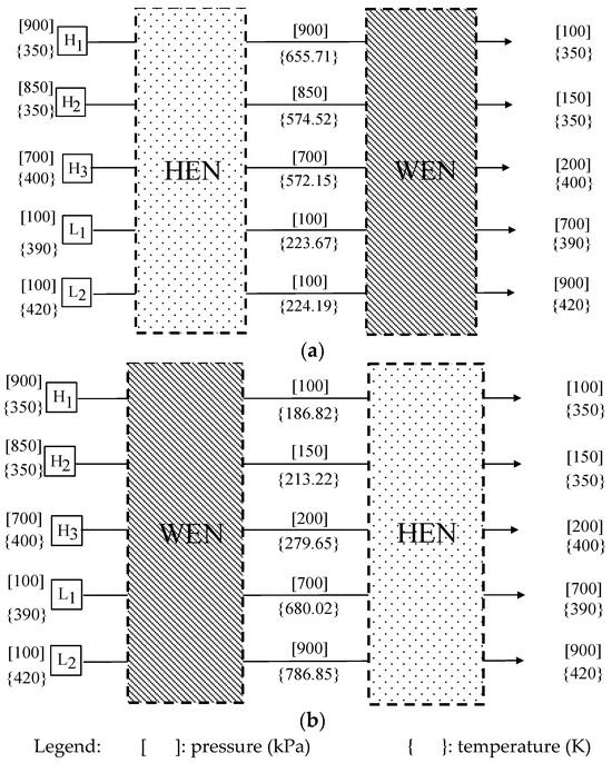
Figure 8.
(a) HEN located before the WEN design and (b) HEN located after the WEN design for Case 2.
A more detailed study of their energy recovery capabilities and annual operating costs is listed in Table 6.

Table 6.
Energy recovery and operation cost comparison based on the HEN location for Case 2.
It is shown that the HIWEN design where a HEN is placed before the WEN would cost 6,909 k$/yr, which is 48.4% of the cost for the HIWEN with a HEN placed after the WEN (14,457 k$/yr). Note that the total number of work transfer units (5) and heat transfer units (7) for the designs are estimated to be the same, and the annualized capital costs are also very close. Thus, a HIWEN is synthesized with a HEN placed before the WEN. Figure 9a,b depict, respectively, the flowsheets of the WEN and the HEN. A final design of the HIWEN is obtained by combining the WEN and the HEN, which is shown in Figure 9c.
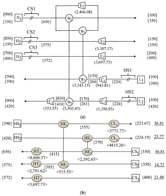
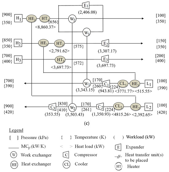
Figure 9.
Flowsheet of the heat-integrated work exchange network for Case 2: (a) the WEN, (b) the HEN, and (c) the HIWEN.
Cost comparison with known designs. The TAC, including the annualized capital cost (CAPEX) and the operating cost (OPEX), is used to compare the design in Figure 9c with the designs by Onishi et al. [7] and Huang and Karimi [8]. To ensure a fair comparison, the same assumptions are used in cost calculation, such as formulation, equipment cost coefficient, fixed cost, and utility cost. Their studies used SSTC units for mechanical energy recovery. The capital cost of external expanders () is computed as follows:
where is the external expander fixed cost and is assumed to be 200 k$/year; is the cost coefficient and is equal to 1 k$/year; and is the flowrate of stream flows through the expander. The capital cost of external compressors () is computed using the following formula:
where is the external compressor fixed cost and is assumed to be 250 k$/year; is the cost coefficient and is equal to 1 k$/year; and is the flowrate of stream flows through the compressor. The capital costs of heat exchangers, heaters, and coolers () are computed as follows:
where is the heat exchanger fixed cost and is assumed to be 3 k$/year; is the cost coefficient and is equal to 0.03 k$/year; is the heat exchanger area; and is the exponent for the area cost of the HE and is equal to 1.
The capital cost of the work exchanger () is computed as follows:
where S is the volume of one vessel and cost parameters assuming stainless steel, the pressure tolerance of 1034 MPa for a vessel and 5 MPa for valves are 995.78 and 0.36 for and , respectively. Amini-Rankouhi and Huang provide a chart for the cost estimation of a WE based on the volume of the displacement vessel made of stainless steel, working in different conditions with a maximum pressure tolerance of the vessels and valves [10].
The operating cost is estimated using the following formula:
where is the cost of electricity ($/kWh); is the cost of steam used as a heating utility ($/kWh); is the cost of cooling water used as a cooling utility; and represent the heat duty of the heating and cooling utilities, respectively; is the total number of heaters; and is the total number of coolers.
The utility cost is listed in Table 6. The cost estimation of all of the units for Case 2 shown in Figure 9c is summarized in Table 7, which gives a TAC of $9,666,994.

Table 7.
CAPEX and OPEX of units in Case 2.
Table 8 provides a detailed design comparison of this HIWEN system with those by Onishi et al. [7] and Huang and Karimi [8], whose TACs are, respectively, 5.67% and 8.64% higher.

Table 8.
Performance comparison of HIWENs to different methods for Case 2.
For the capital cost estimation of the piston-type WEs in our design, the cost formula by Amini-Rankouhi and Huang is used [10].
In general, the design in Figure 9c is less complicated and easier to implement than the known designs. Note that due to pressure and temperature correlations, the assumptions made regarding the heat integration made an impact on the total amount of energy that can be provided by the high-pressure streams for pressurizing low-pressure streams. In this case, the total mechanical energy recovery is not necessarily the best parameter for comparison. The capital cost for our design is higher than the design by Huang and Karimi; this can be explained as the result of more compressors and expanders, in addition to the cost of work exchangers [8]. The operating cost of our design is significantly lower than the design by Huang and Karimi because of lower utility consumption [8].
8. Concluding Remarks
In this paper, a thermodynamic-model-based synthesis methodology for designing cost-effective heat-integrated work exchanger networks (HIWENs) that can recover significant amounts of mechanical and thermal energies was introduced. Using this methodology, the maximum amount of mechanical energy recoverable by piston-type work exchangers estimated by the methodology by Amini-Rankouhi and Huang can be fully implemented into the network design, and heat integration can ensure that all the process stream specifications regarding temperature can be achieved [24]. The synthesis methodology is systematic and general. The two case studies have demonstrated methodological efficacy. Each of these studies created simple HIWEN designs, which lowered the TAC compared to previous works. The first study decreased the TAC by 42% due to the addition of a HEN and a decrease in compression utility. The second case study, while having only a slightly lower TAC than previous studies, significantly improved the operating costs, lowering them very significantly.
Future work will be in two directions. First, the current method for WEN design modification after heat integration is basically an exhaustive search approach for design modification. In fact, the authors of this study are fully aware that even after the implementation of the design modification to produce the final HIWEN, the approach used in this study does not guarantee the global optimality of the solution. The simultaneous synthesis of a hybrid network containing work transfer units (work exchangers, compressors, and expanders) and heat transfer units (heat exchangers, heaters, and coolers) would produce better results for the TAC than the current approach, especially when the minimum TAC is targeted. However, such a derived hybrid network may be more difficult to control, especially as the controls of the intermediate and final target pressures and temperatures of each stream have close interaction. The current approach is more straightforward, and the resultant networks are relatively easier to control. Thus, the authors of this study intend to develop a simultaneous synthesis approach that minimizes the TAC. Second, the current methodology will be applied to a number of real-world problems, such as ammonia manufacturing, hydrogen manufacturing, and LNG production in the gas processing industry.
Author Contributions
Conceptualization: Y.H.; Data curation: A.A.-R. and A.S.; Formal analysis: Y.H., A.A.-R., and A.S.; Methodology: Y.H. and A.A.-R.; Project administration and supervision: Y.H.; Resources: Y.H., A.A.-R., and A.S.; Software: Y.H., A.A.-R., and A.S.; Validation: Y.H., A.A.-R., and A.S.; Visualization: Y.H., A.A.-R., and A.S.; Writing—original draft: A.A.-R. and A.S.; Writing—review and editing: Y.H. and A.S. All authors have read and agreed to the published version of the manuscript.
Funding
This work is supported in part by the U.S. National Science Foundation (No. 2031385 and 2348993).
Data Availability Statement
Available upon request.
Conflicts of Interest
The authors declare no conflicts of interest.
Nomenclature
| NH | the number of high-pressure streams |
| NL | the number of low-pressure streams |
| the matrix containing all of the identified pressure intervals between all of the pairs of high-pressure and low-pressure streams | |
| the source pressure of the high-pressure stream | |
| the target pressure of the high-pressure stream | |
| the source pressure of the low-pressure stream | |
| the target pressure of the low-pressure stream | |
| the matrix containing the pressure intervals of the work exchangers | |
| the lower bound of the pressure exchange interval for the low-pressure stream | |
| the upper bound of the pressure exchange interval for the low-pressure stream | |
| the vector of the streams’ source pressures | |
| the vector of the streams’ target pressures | |
| the vector of the streams’ inlet temperatures of a work exchanger network | |
| the vector of the streams’ outlet temperatures of a work exchanger network | |
| the vector of the streams’ source temperatures | |
| the vector of the streams’ target temperatures | |
| the vector containing the compression needed from external sources | |
| the vector containing the expansion needed from external sources | |
| the vector of the mechanical energy that can be provided by high-pressure streams | |
| the vector of the mechanical energy required by low-pressure streams | |
| the maximum amount of recoverable mechanical energy | |
| the matrix containing the workloads of the work exchangers | |
| the matrix storing all of the calculated energy transfer data | |
| the vector containing information about whether each individual high-pressure stream can provide sufficient mechanical energy to low-pressure streams | |
| ΔPmin | the minimum driving pressure differential |
| ΔTmin | the minimum driving temperature differential |
References
- Energetics Inc. Manufacturing Energy and Carbon Footprint. Prepared for the U.S. Department of Energy, Advanced Manufacturing Office; Energetics Inc.: Washington, DC, USA, 2014. [Google Scholar]
- Huang, Y.L.; Fan, L.T. Analysis of a work exchanger network. Ind. Eng. Chem. Res. 1996, 35, 3528–3538. [Google Scholar] [CrossRef]
- Deng, J.Q.; Shi, J.Q.; Zhang, Z.X.; Feng, X.A. Thermodynamic analysis on work transfer process of two gas streams. Ind. Eng. Chem. Res. 2010, 49, 12496–12502. [Google Scholar] [CrossRef]
- Chen, H.; Feng, X. Graphical approach for targeting work exchange networks. World Acad. Sci. Enginerring Technol. 2012, 6, 977–981. [Google Scholar]
- Liu, G.L.; Zhou, H.; Shen, R.J.; Feng, X. A graphical method for integrating work exchange network. Appl. Energy 2014, 114, 588–599. [Google Scholar] [CrossRef]
- Razib, M.S.; Hasan, M.M.F.; Karimi, I.A. Preliminary synthesis of work exchange networks. Comput. Chem. Eng. 2012, 37, 262–277. [Google Scholar] [CrossRef]
- Onishi, V.C.; Ravagnani, M.; Caballero, J.A. Simultaneous synthesis of work exchange networks with heat integration. Chem. Eng. Sci. 2014, 112, 87–107. [Google Scholar] [CrossRef]
- Huang, K.; Karimi, I. Work-heat exchanger network synthesis (WHENS). Energy 2016, 113, 1006–1017. [Google Scholar] [CrossRef]
- Du, J.; Zhuang, Y.; Liu, L.L.; Li, J.L.; Fan, J.; Meng, Q.W. Synthesis of indirect work exchanger network based on transhipment model. Comput. Aided Chem. Eng. 2015, 37, 1139–1144. [Google Scholar]
- Amini-Rankouhi, A.; Huang, Y. Mechanical energy recovery through work exchanger network integration: Challenges and opportunities. Comput. Aided Chem. Eng. 2018, 44, 409–414. [Google Scholar]
- Deng, J.Q.; Cao, Z.; Zhang, D.B.; Feng, X. Integration of energy recovery network including recycling residual pressure energy with pinch technology. Chin. J. Chem. Eng. 2017, 25, 453–462. [Google Scholar] [CrossRef]
- Fu, C.; Gundersen, T. Heat, and work integration: Fundamental insights and applications to carbon dioxide capture processes. Energy Convers. Manag. 2016, 121, 36–48. [Google Scholar] [CrossRef]
- Yu, H.; Gendersen, T. Review of work exchange networks (WENs) and work and heat exchange networks (WHENs). Chem. Eng. Trans. 2017, 61, 1345–1356. [Google Scholar]
- Yu, H.; Fu, C.; Vikse, M.; He, C.; Gundersen, T. Identifying optimal thermodynamic paths in work and heat exchange network synthesis. AIChE J. 2018, 65, 549–561. [Google Scholar] [CrossRef]
- Yu, H.; Vikse, M.; Anantharaman, R.; Gundersen, T. Model reformulations for work and heat exchange network (WHEN) synthesis problems. Comput. Chem. Eng. 2019, 125, 89–97. [Google Scholar] [CrossRef]
- Hamedi, H.; Karimi, I.; Gundersen, T. Simulation-based approach for integrating work within heat exchange networks for sub-ambient processes. Energy Convers. Manag. 2020, 203, 112276. [Google Scholar] [CrossRef]
- Huang, Y.; Zhuang, Y.; Zhuang, L.; Du, J. Synthesis of Work-integrated Heat Exchanger Networks Coupled with Organic Rankine Cycles. Chem. Eng. Trans. 2023, 103, 139–144. [Google Scholar]
- Pavão, L.; Costa, C.; Ravagnani, M. A new framework for work and heat exchange network synthesis and optimization. Energy Convers. Manag. 2019, 183, 617–632. [Google Scholar] [CrossRef]
- Pavão, L.; Mirandaa, C.B.; Caballerob, J.A.; Ravagnani, M.; Costa, C. Multiperiod work and heat integration. Energy Convers. Manag. 2021, 227, 113587. [Google Scholar] [CrossRef]
- Santos, L.; Costa, C.; Caballero, J.; Ravagnani, M. Synthesis and optimization of work and heat exchange networks using an MINLP model with a reduced number of decision variables. Appl. Energy 2020, 262, 114441. [Google Scholar] [CrossRef]
- Santos, L.; Costa, C.; Caballero, J.; Ravagnani, M. MINLP model for work and heat exchange networks synthesis considering unclassified streams. Comput. Aided Chem. Eng. 2022, 51, 793–798. [Google Scholar]
- Zhuang, Y.; Zhang, L.; Liu, L.; Du, J.; Shen, S. An upgraded superstructure-based model for simultaneous synthesis of direct work and heat exchanger networks. Chem. Eng. Res. Des. 2020, 159, 377–394. [Google Scholar] [CrossRef]
- Ibric, N.; Fu, C.; Gundersen, T. Simultaneous optimization of work and heat exchange networks. Energies 2024, 17, 1753. [Google Scholar] [CrossRef]
- Amini-Rankouhi, A.; Huang, Y. Prediction of maximum recoverable mechanical energy via work integration: A Thermodynamic Modeling and Analysis Approach. AIChE J. 2017, 63, 4814–4826. [Google Scholar] [CrossRef]
- Amini-Rankouhi, A.; Huang, Y. Modeling and simulation of a piston-type work exchanger for mechanical energy recovery. Ind. Eng. Chem. Res. 2019, 58, 18292–18300. [Google Scholar] [CrossRef]
- Walas, S.M. Chemical Process Equipment—Selection and Design. In Butterman-Heinemam Series; Gulf Professional Publishing: Houston, TX, USA, 1990. [Google Scholar]
- Yee, T.; Grossman, I. Simultaneous optimization models for heat integration—II. Heat exchanger network synthesis. Comput. Chem. Eng. 1990, 14, 1165–1184. [Google Scholar] [CrossRef]
- Linnhoff, B. Pinch analysis—A state-of-the-art overview. Chem. Eng. Res. Des. 1993, 71, 503–522. [Google Scholar]
Disclaimer/Publisher’s Note: The statements, opinions and data contained in all publications are solely those of the individual author(s) and contributor(s) and not of MDPI and/or the editor(s). MDPI and/or the editor(s) disclaim responsibility for any injury to people or property resulting from any ideas, methods, instructions or products referred to in the content. |
© 2024 by the authors. Licensee MDPI, Basel, Switzerland. This article is an open access article distributed under the terms and conditions of the Creative Commons Attribution (CC BY) license (https://creativecommons.org/licenses/by/4.0/).