Article

Performance Evaluation of CO2 + SiCl4 Binary Mixture in Recompression Brayton Cycle for Warm Climates

by
Muhammad Ehtisham Siddiqui
* and
Khalid H. Almitani
Mechanical Engineering Department, Faculty of Engineering, King Abdulaziz University, Jeddah 21589, Saudi Arabia
*
Author to whom correspondence should be addressed.
Processes 2024, 12(10), 2155; https://doi.org/10.3390/pr12102155
Submission received: 6 September 2024 / Revised: 25 September 2024 / Accepted: 30 September 2024 / Published: 2 October 2024

Abstract

:
This work demonstrates the potential of CO2 + SiCl4 binary mixture as a working fluid for power generation cycle. Recompression Brayton cycle configuration is considered due to its proven record of high performance for medium- to high-temperature sources. The objective of this study is to assess the thermodynamic performance of a recompression Brayton cycle using a CO2 + SiCl4 binary mixture as a working fluid, particularly under warm climate conditions. The cycle is simulated using the Peng–Robinson equation of state in Aspen Hysys (v11) software, and the model is validated by comparing VLE data against experimental data from the literature. The analysis involves the assessment of cycle’s thermal efficiency and exergy efficiency under warm climatic conditions, with a minimum cycle temperature of 40 °C. The results demonstrate a notable improvement in the cycle’s thermodynamic performance with CO2 + SiCl4 binary mixture compared to pure CO2. A small concentration (5%) of SiCl4 in CO2 increases the thermal efficiency of the cycle from 41.7% to 43.4%. Moreover, irreversibility losses in the cooler and the heat recovery unit are significantly lower with the CO2 + SiCl4 binary mixture than with pure CO2. This improvement enhances the overall exergy efficiency of the cycle, increasing it from 62.1% to 70.2%. The primary reason for this enhancement is the substantial reduction in irreversibility losses in both the cooler and the HTR. This study reveals that when using a CO2 + SiCl4 mixture, the concentration must be optimized to avoid condensation in the compressor, which can cause physical damage to the compressor blades and other components, as well as increase power input. This issue arises from the higher glide temperature of the mixture at increased SiCl4 concentrations and the limited heat recovery from the cycle.

1. Introduction

In recent decades, carbon dioxide (CO2) has been proven to be an efficient alternative working fluid for power generation cycles with a medium to high heat source, whether subcritical, transcritical, or supercritical [1,2,3,4]. This is mainly due to the thermodynamic properties of the carbon dioxide near its critical point, which helps in reducing compression work. Over the last two decades, there has been growing interest in power generation cycle using CO2 as an alternative to steam Rankine cycle. CO2 offers superior energetic and exergetic performance than steam-driven power cycles that are inherently inefficient due to high irreversibility losses associated with a phase change during the heat rejection process [5]. Moreover, CO2 is eco-friendly and requires relatively compact turbomachinery [6,7]. CO2-driven power generation cycles have also been extensively studied for various types of heat sources, including nuclear, solar, and waste heat recovery modules [8,9,10,11,12,13].
From a design point of view, CO2 as a working fluid must be compatible with different cycle components, especially pumps, compressors, and heat exchangers. Compressors must be designed to operate near the critical state of CO2, as a slight change in the inlet conditions (temperature and pressure) can lead to the initiation of dew formation near compressor blades due to the local acceleration of the fluid [14]. The critical pressure of CO2 is nearly 7.4 MPa, which is generally the minimum cycle pressure. Therefore, the cycle operating above critical pressure must have components specially designed to withstand extremely high pressures. Among heat exchangers, printed circuit heat exchanger (PCHE) technology is the most promising to use for supercritical carbon dioxide (sCO2) cycles [15,16]. There are many studies available on PCHEs in the context of their use for supercritical carbon dioxide applications [17,18]. Wang et al. investigated the structural integrity of PCHEs [19]; they analyzed how temperature, pressure, and the variations between them impact stress levels in PCHEs. Their work suggests the structural robustness of PCHEs employed in supercritical carbon dioxide Brayton cycles. Liu et al. investigated the heat transfer characteristics of CO2 in PCHE in transcritical and supercritical states. The suggested heat transfer correlation works well with the experimental findings [20].
From an ambient operating conditions point of view, warm and hot regions do not allow CO2 to cool down to its near critical temperature (nearly 31 °C), and so the cycle loses the advantage that CO2 offers. Studies found in the literature suggest that the use of proper additives to CO2 potentially improves the overall thermodynamic performance of the power generation cycle operating in warm and hot environments [21,22,23]. Various additives for CO2, primarily organic fluids, have recently been proposed to enhance the critical temperature and thereby mitigate this issue [24,25]. The selection of additives is not a straightforward process; it depends on multiple factors, including cycle maximum operating temperature and pressure, ambient conditions, compatibility with cycle components, thermal stability, and so on. Most organic fluids, commercially available ones and those used in organic Rankine cycles, are thermal unstable when operated at higher temperatures. The thermal breakdown threshold for some of these organic fluids is listed in Table 1. For this reason, organic Rankine power generation systems generally operate below 350 °C [26].
Building upon the work carried out and present in the literature, this study explores how incorporating SiCl4 can further improve the performance of CO2-based cycles, especially in warm climates where pure CO2 has a limited cooling capacity. In essence, the present work is motivated by a recent proposal from Doninelli et al. [38] regarding the use of the novel fluid silicon tetrachloride (SiCl4) as a potential additive to CO2. Through an experimental evaluation, they found that the CO2 + SiCl4 mixture exhibited remarkable thermal stability, withstanding temperatures exceeding 650 °C without decomposition. The literature also suggests the usage of titanium tetrachloride (TiCl4) as an additive for high-temperature operations due to its high thermal stability, which is nearly 500 °C [39,40]. However, the rate of the decomposition of SiCl4 is much slower than TiCl4. Moreover, the manufacturing process of solar-grade silicon is accompanied by a substantial byproduct in the form of silicon tetrachloride (SiCl4) [41]. This is reflected in the high market availability of SiCl4, which thus makes it relatively cheaper. The current study aims to assess the thermodynamic performance of the recompression Brayton cycle (RBC) using pure CO2 and a CO2 + SiCl4 mixture at varying molar concentrations of SiCl4. The performance indicators are assessed using energy and exergy analyses of the cycle. The cycle is studied for warm climate regions with a minimum cycle temperature of 40 °C.

2. System Arrangement: Modeling and Operating Parameters

The recompression Brayton cycle (RBC) is considered for studying the CO2 + SiCl4 binary mixture. For medium to high source temperatures, the simple Brayton cycle’s efficiency is limited due to restricted heat recovery resulting from the pinch temperature in the heat exchange process. This limitation is overcome by employing RBC configuration, which allows for more effective heat recovery, thereby enhancing the overall performance of the cycle [42,43,44].
The RBC layout is shown in Figure 1a. The system is designed with two compression processes and two heat recovery stages. Notably, at the cycle’s minimum pressure–temperature operating condition (at the cooler outlet), the CO2 + SiCl4 binary mixture can be cooled down to the liquid phase; therefore, a pump is utilized instead of a compressor (which is originally used in a pure sCO2 cycle). After the turbine discharge at state 2, the working fluid undergoes a series of heat recovery processes. It first flows through the high-temperature recuperator (HTR) and then proceeds to the low-temperature recuperator (LTR). The working fluid exiting the LTR splits into two paths. One stream moves toward the cooler, where it releases heat to the ambient sink (with water utilized as the coolant), followed by a compression process to achieve the cycle’s high pressure. The second stream combines with the first stream after being compressed in the compressor and preheated in the LTR. The combined flow at state 9 undergoes heat recovery in the HTR before being heated further in the heater to reach the target turbine inlet temperature (TIT).
Figure 1b presents the temperature–entropy diagram of the cycle with a 2% molar concentration of SiCl4 in the CO2 + SiCl4 binary mixture. It can be seen that the temperature of the mixture at the turbine exit is significantly higher than the ambient temperature. Therefore, the available heat energy is recuperated in the HTR, followed by the LTR, before being rejected in the cooler. In other words, an increased temperature difference between the hot and cold streams in either the HTR or LTR will result in higher heat recovery, reflected by the higher exit temperature of the cold stream from the HTR and LTR. Improvement in heat recovery will result in decreased heat input and improved overall performance of the cycle. The state of the mixture at the pump inlet is saturated liquid, while it is in a supercritical state at the compressor inlet.
The cycle is simulated in Aspen Hysys (V11), and the Peng–Robinson model is employed to calculate the thermodynamic properties of the CO2 and CO2 + SiCl4 binary mixture. The model has been validated in previous studies for various configurations of the cycle, including RBC for pure CO2 as a working fluid [1]. The current study utilizes CO2 + SiCl4 mixture as a working fluid; thus, it is imperative to validate the model (Peng–Robinson) used to obtain the thermo-physical properties in the analysis. Therefore, the vapor–liquid equilibrium (VLE) data obtained from the model are compared with recently published experimental data by Doninelli et al. [38]. Figure 2 shows the vapor–liquid equilibrium (VLE) diagram for the CO2 + SiCl4 mixture obtained using the Peng–Robinson model at mixture temperatures of 35 °C, 60 °C, and 70 °C. The experimental data for bubble pressure are also plotted. It should be noted that experimental data from the cited literature are only available for the molar concentrations of CO2 between 80% and 90%. Table 2 shows the percentage errors in bubble pressures between the experimental data and the model predictions. It is observed that the model produced very good results, especially for molar concentrations above 85%, where the error is less than 2% [38]. The operating conditions of the cycle are provided in Table 3.

3. Mathematical Model for the Quantitative Assessment of the Cycle

To assess the energetic performance of the cycle shown in Figure 1a, the first law efficiency ( η t h ) of the cycle is calculated as follows:
η t h = ( W ˙ T W ˙ P W ˙ C ) / ( Q ˙ i n )
where W ˙ T is the power output of the turbine; W ˙ P and W ˙ C represent the power consumption of the pump and the compressor, respectively. Q ˙ i n denotes the heat input needed to operate the cycle at the desired temperature and pressure.
To evaluate the exergetic performance of the cycle, component wise losses are calculated. The rate of exergy at any given state point ( ψ ˙ i ) in the cycle is obtained as follows:
ψ ˙ i = m ˙ i h i T o s i
where m ˙ i , h i , and s i , respectively, denote the mass flow rate, specific enthalpy, and specific entropy at any given state point in the cycle. T o denotes the temperature of the dead state, as specified in Table 3.
The rate of exergy loss incurred by different components in the cycle is calculated as follows:
ψ ˙ l o s s ,   T = ψ ˙ 1 ψ ˙ 2 W ˙ T
ψ ˙ l o s s , P = W ˙ P ψ ˙ 6 ψ ˙ 5
ψ ˙ l o s s ,   C = W C 2 ψ ˙ 8 ψ ˙ 4 b
ψ ˙ l o s s ,   H T R = ψ ˙ 2 ψ ˙ 3 ψ ˙ 10 ψ ˙ 9
ψ ˙ l o s s ,   L T R = ψ ˙ 3 ψ ˙ 4 ψ ˙ 7 ψ ˙ 6
ψ ˙ l o s s ,   C o o l e r = ψ ˙ 4 a ψ ˙ 5 + ψ ˙ 12 ψ ˙ 11
ψ ˙ l o s s ,   H e a t e r = ψ ˙ 14 ψ ˙ 13 ψ ˙ 1 ψ ˙ 10
The exergy efficiency ( η e x ) of the cycle is calculated as follows:
η e x = 1 ψ ˙ l o s s ,   n e t ψ ˙ i n p u t   × 100
where ψ ˙ l o s s ,   n e t represents the net rate of exergy loss in the cycle which can be obtained by adding the rate of exergy losses occurring in various components of the cycle from Equations (3)–(9). The rate of exergy input ( ψ ˙ i n p u t ) to the cycle is considered the rate of exergy loss by the hot air (heat source) in the heater, and it is calculated as follows:
ψ ˙ i n p u t = ψ ˙ 14 ψ ˙ 13
It is important to note that the presented mathematical model assumes that the cycle operates under steady-state conditions, where compression and expansion processes are considered adiabatic. Furthermore, the model disregards pressure losses across the various components and within the interconnecting pipelines of the cycle.

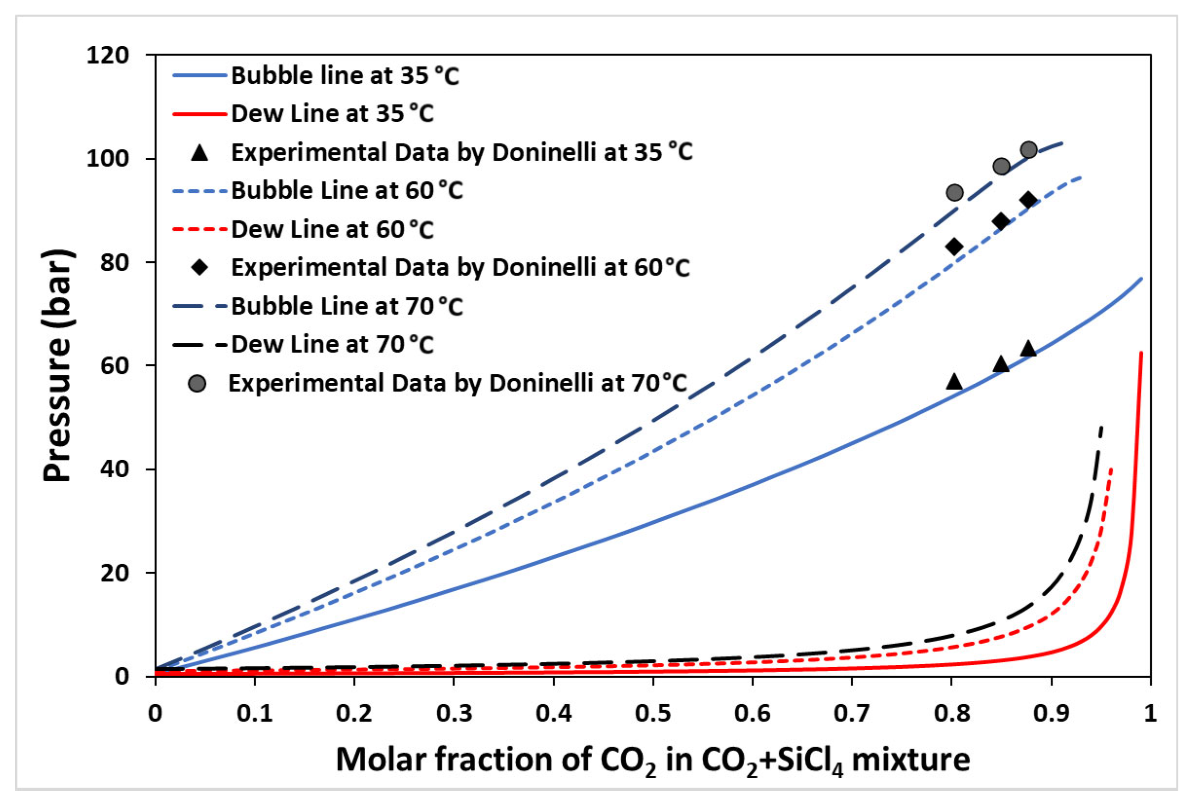
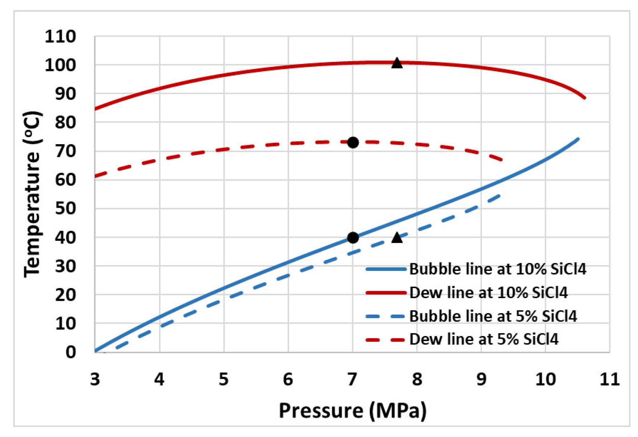
4. Findings and Analyses

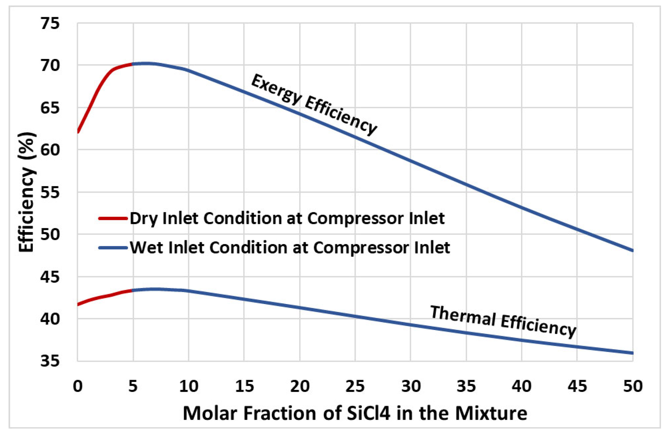
4.1. Factors Influencing Cycle Performance

The thermodynamic performance of the cycle shown in Figure 1a depends on multiple factors, including the turbine inlet temperature and pressure, the mass flow ratio ( m ˙ 4 b / m ˙ 4 ) at the “Flow Divider”, the cycle minimum pressure and temperature (at the pump inlet), and the pressure losses in the heat exchangers and in the pipelines connecting various components of the cycle. In the current investigation, the turbine inlet pressure and the flow ratio are the optimization variables, whereas the fixed operating parameters are mentioned in Table 3. Figure 3 shows how the efficiency of the system is affected by two factors: the ratio of the flow rates and the pressure at the turbine inlet. As evident from these plots, fixing either the turbine inlet pressure (TIP) or the flow ratio results in the cycle’s thermal efficiency reaching the same maximum value. Therefore, for the remaining study, the flow ratio is fixed at 30%, and only the turbine inlet pressure is considered an optimization variable. Readers are referred to the authors’ previous work for a detailed analysis of parameters such as flow ratio, turbine inlet pressure, and minimum allowable pinch temperature, etc., on the cycle performance [42,45].
Figure 4 presents the plots of thermal efficiency and vapor fraction at the compressor inlet (state 4b in Figure 1) versus turbine inlet pressure. As observed from the plots, the thermal efficiency of the cycle increases with increasing turbine inlet pressure, regardless of the mixture concentration. However, it is noteworthy that the system operates more efficiently when the mixture contains 6% silicon tetrachloride (SiCl4) compared to when the SiCl4 percentage is 4%. For example, at a 25 MPa turbine inlet pressure, the thermal efficiency of the cycle is 43.5% when operating with a 6% mole fraction of SiCl4 in the mixture, and 43.1% with a 4% mole fraction. On the other hand, increasing the mole fraction of SiCl4 in the mixture leads to the decreased vapor fraction of the working fluid at the compressor inlet (as evident from Figure 4). This means that the compressor will experience a wet inlet condition if the cycle is operated with a mole fraction of SiCl4 in the mixture at or above 6%. This is mainly due to the increasing temperature glide with increasing the molar concentration of SiCl4 in the mixture. Figure 5 presents bubble and dew lines obtained for 5% and 10% molar concentrations of SiCl4. Recalling that the pump inlet temperature is fixed at 40 °C, this corresponds to glide temperatures of nearly 33 °C and 61 °C for 5% and 10% molar concentrations of SiCl4 in the mixture, respectively. This implies that the LTR must recover sufficient heat energy to achieve the required glide temperature for an isobaric heat transfer process, ensuring a dry inlet condition at the compressor inlet. It is important to remember that this study does not consider pressure drops in the components, which is something that cannot be avoided in real-world situations. As a result, the temperature glide phenomenon presents significant challenges for the design and operation of the LTR. In simpler terms, to accommodate these varying temperature profiles during the phase change process, the LTR’s design may need to incorporate multiple zones with different temperatures to maintain an effective temperature difference and heat transfer throughout the phase change region.

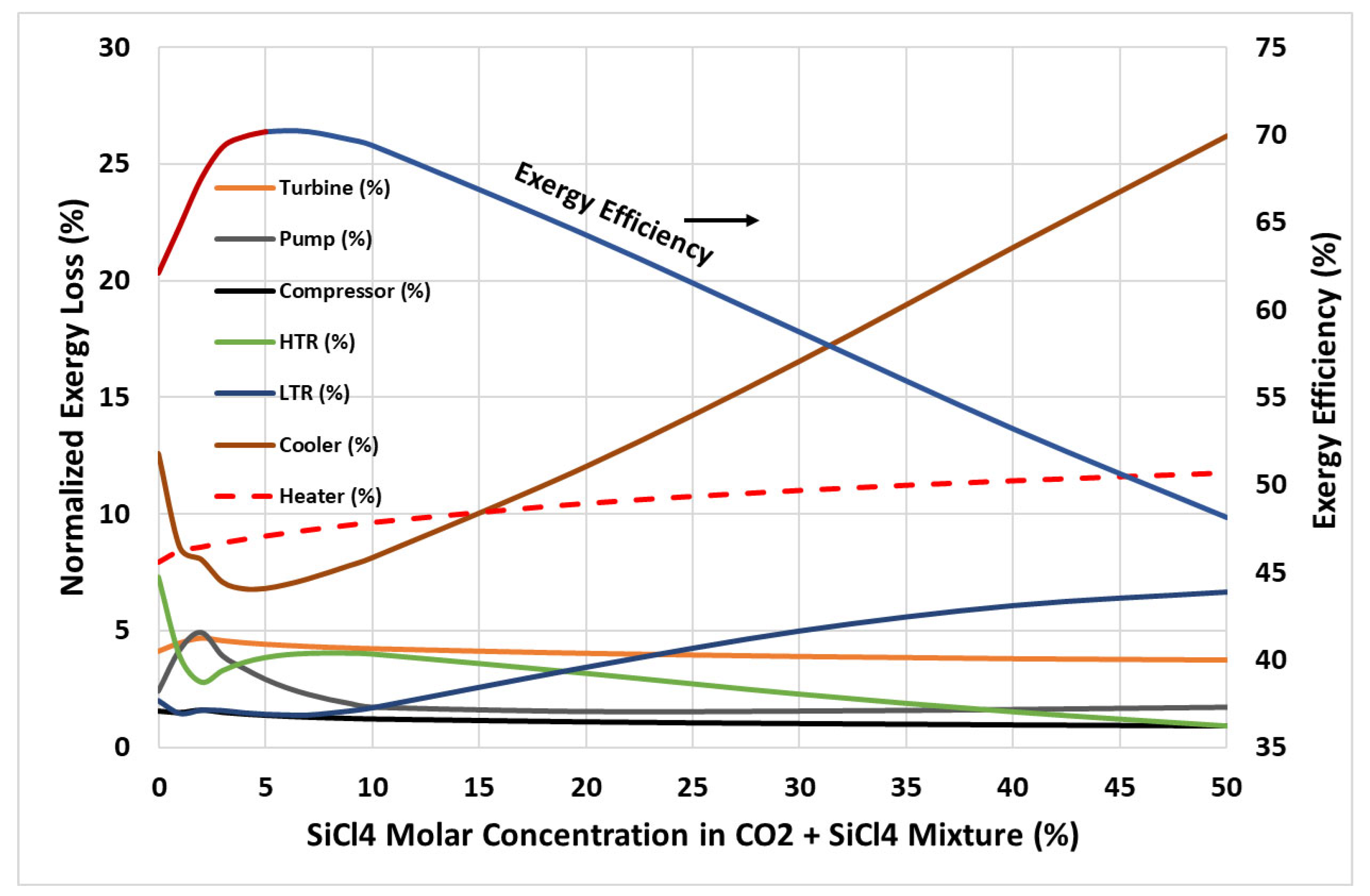
4.2. Energy and Exergy Performance

This section discusses the energy and exergy performance of the cycle. As evident from the study in the section above, the cycle attains the maximum thermal efficiency when operated at optimal turbine inlet pressure, regardless of the molar fraction of the additive (SiCl4) in the CO2-based binary mixture. Therefore, a case study was conducted to find the maximum attainable performance of the cycle at various molar concentrations of SiCl4 in the mixture. Figure 6 presents the thermal efficiency and the exergy efficiency of the cycle obtained at optimized turbine inlet pressure. It is observed that adding a small amount of SiCl4 to CO2 significantly improved the energetic and exergetic performance of the cycle. Considering energy performance, the thermal efficiency of the cycle increases with the increasing molar fraction reaching a maximum of nearly 43.5% at a 7% molar fraction of SiCl4 in the mixture; this represents an increase of nearly 1.75 percentage points in thermal efficiency compared to pure CO2 (which is nearly 41.75%). As mentioned earlier, when the mole fraction of SiCl4 increases, the temperature glide also increases. However, if not enough heat is recovered in the LTR, this can result in a wet inlet condition at the compressor. It is important to note that the compressor will experience this wet inlet condition if the mole fraction of SiCl4 is above 5% (see Figure 6). To ensure dry inlet conditions at the compressor inlet, the optimal molar fraction of SiCl4 in the mixture is 5%, which achieves a nearly 43.36% thermal efficiency of the cycle, considered the highest possible in the current study. The thermal efficiency curve exhibits a steady decline, indicating poor heat recovery in the LTR and increased energy input during the compression process. A similar trend is observed for the exergy efficiency; the cycle achieves a maximum of nearly 70% exergy efficiency at a 5% molar concentration of SiCl4. This represents a significant improvement of 8 percentage points in the exergy performance compared to pure CO2.
The analysis of exergy loss rates across various components highlights critical insights into the performance of the cycle. The rate of exergy loss in various components, calculated using equations Equations (2)–(9) normalized by the net rate of the exergy input, is plotted in Figure 7 along with the exergy efficiency curve as a reference. It is found that the rate of exergy loss in various components of the cycle is less than 5% of the net rate of the exergy input, except for the cooler and heater. Focusing on the dry compressor inlet with SiCl4 concentrations between 0% and 5%, a significant drop in irreversibility losses in the cooler and HTR is observed, compared to pure CO2, which is ultimately reflected in an improved exergy performance of the cycle (refer to Figure 6). However, for molar concentrations above 5%, the increase in irreversibility losses in the low-temperature recuperator (LTR) and cooler becomes significant. This trend is associated with the increased temperature glide observed at higher SiCl4 concentrations, leading to greater losses during the phase change in the mixture in the heat exchange process.

5. Conclusions

The thermodynamic performance of the CO2 + SiCl4 binary mixture as a working fluid for the recompression Brayton cycle was evaluated through analyses of its thermal efficiency and exergy efficiency. The cycle was modeled in the commercial software Aspen Hysys (V11) using the Peng–Robinson equation as the thermodynamic model to obtain the thermo-physical properties for CO2 and the CO2 + SiCl4 binary mixture. The model worked well with the experimental findings reported in the literature. The cycle’s performance was assessed for warm climatic conditions with a cycle minimum temperature of 40 °C and turbine inlet temperature of 500 °C. The key outcomes of the present work are highlighted pointwise below.
  • The cycle thermodynamic performance improved significantly when using CO2 + SiCl4 binary mixture as a working fluid compared to pure CO2.
  • At optimal mixture concentration, the thermal efficiency of the cycle improved by 1.6 percentage points, which corresponds to a nearly 4% improvement compared to pure CO2.
  • A great improvement in the exergy performance of the cycle was observed for CO2 + SiCl4 binary mixture. At optimal operating conditions, the exergy efficiency increased by 8 percentage points, reflecting a nearly 13% improvement compared to pure CO2. This was mainly due to a significant decrease in irreversibility losses in the cooler and the HTR.
  • With CO2 + SiCl4 as a working fluid, the energy and exergy performance parameters of the cycle improved with an increased molar concentration of SiCl4 in the mixture to a limit, and then a decline in the performance was observed.
  • The increasing molar concentration of SiCl4 also resulted in a wet inlet condition to the compressor inlet, which resulted from the increasing trend of temperature glide with the increasing molar concentration of SiCl4 in the mixture. This was due to limited heat recovery from the LTR between hot and cold streams.
The current study demonstrates the potential of CO2 + SiCl4 as a working fluid for power generation cycles. However, the scope of this research was limited to the recompression Brayton cycle. Therefore, the authors recommend exploring other configurations, such as the recompression Brayton cycle with partial cooling, to further evaluate performance.
Additionally, the observed temperature glide has a significant impact on the overall efficiency of the cycle due to its effects on heat recovery. Future work should focus on designing heat exchangers optimized for specific temperature–pressure ranges to mitigate these limitations. This targeted approach could enhance the overall performance of the cycle and broaden the applicability of CO2 + SiCl4 in various power generation systems.

Author Contributions

Methodology, M.E.S.; software, M.E.S.; validation, M.E.S.; formal analysis, M.E.S.; investigation, M.E.S. and K.H.A.; resources, K.H.A.; writing—original draft, M.E.S.; writing—review and editing, K.H.A.; funding acquisition, M.E.S. All authors have read and agreed to the published version of the manuscript.

Funding

This research work was funded by Institutional Fund Projects under grant no. (IFPIP: 1367-135-1443). The authors gratefully acknowledge the technical and financial support provided by the Ministry of Education and King Abdulaziz University, DSR, Jeddah, Saudi Arabia.

Data Availability Statement

The original contributions presented in the study are included in the article; further inquiries can be directed to the corresponding author.

Conflicts of Interest

The authors declare no conflict of interest.

Nomenclature

CO2carbon dioxide
hispecific enthalpy at i-th state point in the cycle
HTRhigh-temperature recuperator
LTR low-temperature recuperator
m ˙ i mass flow rate of the working fluid at i-th state point in the cycle
ORCorganic Rankine cycle
PCHEprinted circuit heat exchanger
Q ˙ i n heat input to the cycle
RBCrecompression Brayton cycle
sspecific entropy
SiCl4silicon tetrachloride
TITturbine inlet temperature
T 0 dead-state temperature
VLEvapor–liquid equilibrium
W ˙ T turbine power output
W ˙ P pump power input
W ˙ C compressor power input
η e x exergy efficiency of the cycle
η t h thermal efficiency of the cycle
ψ ˙ i rate of exergy at any i-th state point in the cycle
ψ ˙ l o s s _ T rate of exergy loss in turbine
ψ ˙ l o s s _ P rate of exergy loss in pump
ψ ˙ l o s s _ C rate of exergy loss in compressor
ψ ˙ l o s s _ L T R rate of exergy loss in low-temperature recuperator
ψ ˙ l o s s _ H T R rate of exergy loss in high-temperature recuperator
ψ ˙ l o s s _ C o o l e r rate of exergy loss in cooler
ψ ˙ l o s s _ H e a t e r rate of exergy loss in heater
ψ ˙ l o s s , n e t net rate of exergy loss in condenser
ψ ˙ i n p u t rate of exergy input to the cycle

References

  1. Chen, Y.; Lundqvist, P.; Johansson, A.; Platell, P. A Comparative Study of the Carbon Dioxide Transcritical Power Cycle Compared with an Organic Rankine Cycle with R123 as Working Fluid in Waste Heat Recovery. Appl. Therm. Eng. 2006, 26, 2142–2147. [Google Scholar] [CrossRef]
  2. Santini, L.; Accornero, C.; Cioncolini, A. On the Adoption of Carbon Dioxide Thermodynamic Cycles for Nuclear Power Conversion: A Case Study Applied to Mochovce 3 Nuclear Power Plant. Appl. Energy 2016, 181, 446–463. [Google Scholar] [CrossRef]
  3. Turchi, C.S.; Ma, Z.; Neises, T.W.; Wagner, M.J. Thermodynamic Study of Advanced Supercritical Carbon Dioxide Power Cycles for Concentrating Solar Power Systems. J. Sol. Energy Eng. 2013, 135, 041007. [Google Scholar] [CrossRef]
  4. Yang, M.-H.; Yeh, R.-H. Analyzing the Optimization of an Organic Rankine Cycle System for Recovering Waste Heat from a Large Marine Engine Containing a Cooling Water System. Energy Convers. Manag. 2014, 88, 999–1010. [Google Scholar] [CrossRef]
  5. Cheang, V.T.; Hedderwick, R.A.; McGregor, C. Benchmarking Supercritical Carbon Dioxide Cycles against Steam Rankine Cycles for Concentrated Solar Power. Solar Energy 2015, 113, 199–211. [Google Scholar] [CrossRef]
  6. Yang, Z.; Le Moullec, Y.; Zhang, J.; Zhang, Y. Dynamic Modeling of 5 MWe Supercritical CO2 Recompression Brayton Cycle. AIP Conf. Proc. 2018, 2033, 70003. [Google Scholar] [CrossRef]
  7. Khatoon, S.; Ishaque, S.; Kim, M.H. Modeling and Analysis of Air-Cooled Heat Exchanger Integrated with Supercritical Carbon Dioxide Recompression Brayton Cycle. Energy Convers. Manag. 2021, 232, 113895. [Google Scholar] [CrossRef]
  8. Dostal, V.; Hejzlar, P.; Driscoll, M.J. High-Performance Supercritical Carbon Dioxide Cycle for next-Generation Nuclear Reactors. Nucl. Technol. 2006, 154, 265–282. [Google Scholar] [CrossRef]
  9. Vesely, L.; Dostal, V.; Hajek, P. Design of Experimental Loop with Supercritical Carbon Dioxide. In Next Generation Reactors and Advanced Reactors: Nuclear Safety and Security, Proceedings of the 22nd International Conference on Nuclear Engineering, Prague, Czech Republic, 7 July 2014; American Society of Mechanical Engineers (ASME): New York, NY, USA, 2014; Volume 3. [Google Scholar]
  10. Crespi, F.; Sánchez, D.; Rodríguez, J.M.; Gavagnin, G. A Thermo-Economic Methodology to Select SCO2 Power Cycles for CSP Applications. Renew. Energy 2020, 147, 2905–2912. [Google Scholar] [CrossRef]
  11. Binotti, M.; Astolfi, M.; Campanari, S.; Manzolini, G.; Silva, P. Preliminary Assessment of SCO2 Cycles for Power Generation in CSP Solar Tower Plants. Appl. Energy 2017, 204, 1007–1017. [Google Scholar] [CrossRef]
  12. Gotelip, T.; Gampe, U.; Glos, S. Optimization Strategies of Different SCO2 Architectures for Gas Turbine Bottoming Cycle Applications. Energy 2022, 250, 123734. [Google Scholar] [CrossRef]
  13. Manente, G.; Fortuna, F.M. Supercritical CO2 Power Cycles for Waste Heat Recovery: A Systematic Comparison between Traditional and Novel Layouts with Dual Expansion. Energy Convers. Manag. 2019, 197, 111777. [Google Scholar] [CrossRef]
  14. Romei, A.; Gaetani, P.; Persico, G. Computational Fluid-Dynamic Investigation of a Centrifugal Compressor with Inlet Guide Vanes for Supercritical Carbon Dioxide Power Systems. Energy 2022, 255, 124469. [Google Scholar] [CrossRef]
  15. Meshram, A.; Jaiswal, A.K.; Khivsara, S.D.; Ortega, J.D.; Ho, C.; Bapat, R.; Dutta, P. Modeling and Analysis of a Printed Circuit Heat Exchanger for Supercritical CO2 Power Cycle Applications. Appl. Therm. Eng. 2016, 109, 861–870. [Google Scholar] [CrossRef]
  16. Nikitin, K.; Kato, Y.; Ngo, L. Printed Circuit Heat Exchanger Thermal—Hydraulic Performance in Supercritical CO 2 Experimental Loop “Circuit Imprime” Dans Une Boucle Echangeur de Chaleur a’ Rimentale Au CO2 Supracritique: Performance Expe Thermique et Hydraulique. Int. J. Refrig. 2006, 29, 807–814. [Google Scholar] [CrossRef]
  17. Hu, Z.C.; Wang, K. Effect of Channel Size on the Performance of a PCHE-Based Supercritical CO2 Thermoacoustic Engine. Appl. Therm. Eng. 2024, 236, 121457. [Google Scholar] [CrossRef]
  18. Arslan, F.; Güzel, B. Numerical and Experimental Thermal–Hydraulic Performance Analysis of a Supercritical CO2 Brayton Cycle PCHE Recuperator. Arab. J. Sci. Eng. 2021, 46, 7543–7556. [Google Scholar] [CrossRef]
  19. Wang, J.; Yan, X.; Lu, M.; Sun, Y.; Wang, J. Structural Assessment of Printed Circuit Heat Exchangers in Supercritical CO2 Waste Heat Recovery Systems for Ship Applications. J. Therm. Sci. 2022, 31, 689–700. [Google Scholar] [CrossRef]
  20. Liu, K.; Zhao, F.; Jin, Y.; Hu, C.; Ming, Y.; Liu, Y.; Tian, R.; Liu, S. S–CO2 Heat Transfer Characteristics Analysis in PCHE and Vertical Channel. Prog. Nucl. Energy 2022, 154, 104472. [Google Scholar] [CrossRef]
  21. Shahrooz, M.; Lundqvist, P.; Nekså, P. Performance of Binary Zeotropic Mixtures in Organic Rankine Cycles (ORCs). Energy Convers. Manag. 2022, 266, 115783. [Google Scholar] [CrossRef]
  22. Siddiqui, M.E.; Almatrafi, E.; Bamasag, A.; Saeed, U. Adoption of CO2-Based Binary Mixture to Operate Transcritical Rankine Cycle in Warm Regions. Renew Energy 2022, 199, 1372–1380. [Google Scholar] [CrossRef]
  23. Haroon, M.; Sheikh, N.A.; Ayub, A.; Tariq, R.; Sher, F.; Baheta, A.T.; Imran, M. Exergetic, Economic and Exergo-Environmental Analysis of Bottoming Power Cycles Operating with CO2-Based Binary Mixture. Energies 2020, 13, 5080. [Google Scholar] [CrossRef]
  24. Niu, X.; Ma, N.; Bu, Z.; Hong, W.; Li, H. Thermodynamic Analysis of Supercritical Brayton Cycles Using CO2-Based Binary Mixtures for Solar Power Tower System Application. Energy 2022, 254, 124286. [Google Scholar] [CrossRef]
  25. Shu, G.; Yu, Z.; Tian, H.; Liu, P.; Xu, Z. Potential of the Transcritical Rankine Cycle Using CO2-Based Binary Zeotropic Mixtures for Engine’s Waste Heat Recovery. Energy Convers. Manag. 2018, 174, 668–685. [Google Scholar] [CrossRef]
  26. Invernizzi, C.M.; Iora, P.; Manzolini, G.; Lasala, S. Thermal Stability of N-Pentane, Cyclo-Pentane and Toluene as Working Fluids in Organic Rankine Engines. Appl. Therm. Eng. 2017, 121, 172–179. [Google Scholar] [CrossRef]
  27. Calderazzi, L.; Colonna di Paliano, P. Thermal Stability of R-134a, R-141b, R-13I1, R-7146, R-125 Associated with Stainless Steel as a Containing Material. Int. J. Refrig. 1997, 20, 381–389. [Google Scholar] [CrossRef]
  28. Angelino, G.; Invernizzi, C. Experimental Investigation on the Thermal Stability of Some New Zero ODP Refrigerants. Int. J. Refrig. 2003, 26, 51–58. [Google Scholar] [CrossRef]
  29. Huo, E.; Liu, C.; Xin, L.; Li, X.; Xu, X.; Li, Q.; Wang, S.; Dang, C. Thermal Stability and Decomposition Mechanism of HFO-1336mzz(Z) as an Environmental Friendly Working Fluid: Experimental and Theoretical Study. Int. J. Energy Res. 2019, 43, 4630–4643. [Google Scholar] [CrossRef]
  30. Liu, J.; Liu, Y.; Liu, C.; Xin, L.; Yu, W. Experimental and Theoretical Study on Thermal Stability of Mixture R1234ze(E)/R32 in Organic Rankine Cycle. J. Therm. Sci. 2023, 32, 1595–1613. [Google Scholar] [CrossRef]
  31. Irriyanto, M.Z.; Lim, H.S.; Choi, B.S.; Myint, A.A.; Kim, J. Thermal Stability and Decomposition Behavior of HFO-1234ze(E) as a Working Fluid in the Supercritical Organic Rankine Cycle. J. Supercrit. Fluids 2019, 154, 104602. [Google Scholar] [CrossRef]
  32. Invernizzi, C.M.; Iora, P.; Preßinger, M.; Manzolini, G. HFOs as Substitute for R-134a as Working Fluids in ORC Power Plants: A Thermodynamic Assessment and Thermal Stability Analysis. Appl. Therm. Eng. 2016, 103, 790–797. [Google Scholar] [CrossRef]
  33. Invernizzi, C.; Binotti, M.; Bombarda, P.; Marcoberardino, G.D.; Iora, P.; Manzolini, G. Water Mixtures as Working Fluids in Organic Rankine Cycles. Energies 2019, 12, 2629. [Google Scholar] [CrossRef]
  34. Pasetti, M.; Invernizzi, C.M.; Iora, P. Thermal Stability of Working Fluids for Organic Rankine Cycles: An Improved Survey Method and Experimental Results for Cyclopentane, Isopentane and n-Butane. Appl. Therm. Eng. 2014, 73, 764–774. [Google Scholar] [CrossRef]
  35. Dai, X.; Shi, L.; An, Q.; Qian, W. Screening of Hydrocarbons as Supercritical ORCs Working Fluids by Thermal Stability. Energy Convers. Manag. 2016, 126, 632–637. [Google Scholar] [CrossRef]
  36. Lasala, S.; Invernizzi, C.; Iora, P.; Chiesa, P.; Macchi, E. Thermal Stability Analysis of Perfluorohexane. Energy Procedia 2015, 75, 1575–1582. [Google Scholar] [CrossRef]
  37. Doninelli, M.; Di Marcoberardino, G.; Iora, P.; Gelfi, M.; Invernizzi, C.M.; Manzolini, G. Silicon Tetrachloride as Innovative Working Fluid for High Temperature Rankine Cycles: Thermal Stability, Material Compatibility, and Energy Analysis. Appl. Therm. Eng. 2024, 249, 123239. [Google Scholar] [CrossRef]
  38. Doninelli, M.; Morosini, E.; Di Marcoberardino, G.; Invernizzi, C.M.; Iora, P.; Riva, M.; Stringari, P.; Manzolini, G. Experimental Investigation of the CO2 + SiCl4 Mixture as Innovative Working Fluid for Power Cycles: Bubble Points and Liquid Density Measurements. Energy 2024, 299, 131197. [Google Scholar] [CrossRef]
  39. Wan, Y.; Zhao, X.; Yan, D.; Yang, D.; Li, Y.; Guo, S. Research and Preparation of Ultra Purity Silicon Tetrachloride. AIP Conf. Proc. 2017, 1890, 40026. [Google Scholar] [CrossRef]
  40. Okamoto, Y.; Sumiya, M.; Nakamura, Y.; Suzuki, Y. Effective Silicon Production from SiCl4 Source Using Hydrogen Radicals Generated and Transported at Atmospheric Pressure. Sci. Technol. Adv. Mater. 2020, 21, 482–491. [Google Scholar] [CrossRef]
  41. Cheng, C.; Zhang, C.; Jiang, J.; Ma, E.; Bai, J.; Wang, J. Raman Spectroscopy Characterization of Dissolved Polysilicon Byproduct SiCl4 in Ionic Liquids. J. Spectrosc. 2018, 2018, 2329189. [Google Scholar] [CrossRef]
  42. Siddiqui, M.E.; Almitani, K.H. Proposal and Thermodynamic Assessment of S-CO2 Brayton Cycle Layout for Improved Heat Recovery. Entropy 2020, 22, 305. [Google Scholar] [CrossRef]
  43. Astolfi, M.; Alfani, D.; Lasala, S.; Macchi, E. Comparison between ORC and CO2 Power Systems for the Exploitation of Low-Medium Temperature Heat Sources. Energy 2018, 161, 1250–1261. [Google Scholar] [CrossRef]
  44. Alfani, D.; Astolfi, M.; Binotti, M.; Silva, P.; Macchi, E. Off-Design Performance of CSP Plant Based on Supercritical CO2 Cycles. AIP Conf. Proc. 2020, 2303, 130001. [Google Scholar] [CrossRef]
  45. Siddiqui, M.E.; Taimoor, A.A.; Almitani, K.H. Energy and Exergy Analysis of the S-CO2 Brayton Cycle Coupled with Bottoming Cycles. Processes 2018, 6, 153. [Google Scholar] [CrossRef]
Figure 1. (a) Cycle configuration and (b) temperature–entropy diagram of the cycle.
Processes 12 02155 g001
Figure 2. Vapor–liquid equilibrium diagram depicting the Peng–Robinson model for a CO2 + SiCl4 mixture. The dotted points represent experimental data obtained from the work of Doninelli et al. [38].
Processes 12 02155 g002
Figure 3. Thermal efficiency of the cycle versus (a) flow ratio and (b) turbine inlet pressure.
Processes 12 02155 g003
Figure 4. Cycle thermal efficiency and compressor inlet vapor fraction for 4% and 6% SiCl4 mole fractions in the working fluid mixture.
Processes 12 02155 g004
Figure 5. Saturation pressure and temperature curve of CO2 + SiCl4 binary mixture at 5% and 10% molar concentration. The dots represent state points on the bubble and dew lines corresponding to the bubble pressure at cycle minimum temperature, i.e., 40 °C.
Processes 12 02155 g005
Figure 6. Thermal and exergy efficiency of the cycle versus molar fraction of SiCl4 in CO2 + SiCl4 mixture.
Processes 12 02155 g006
Figure 7. Exergy loss due to irreversibilities in various components of the cycle for molar concentration of SiCl4 in CO2 + SiCl4 mixture.
Processes 12 02155 g007
Table 1. Maximum operating temperature limits of various potential working fluids for ORCs.
Organic FluidsChemical FormulaThermal Stability Cutoff (°C)Reference
R-1311CF3I102[27]
R-141bC2H3Cl2F90[27]
HFC-245faC3F5H3300–320[28]
HFC-143aC2H3F3350[28]
HFC-236faC3H2F6400[28]
HFC-23CHF3400[28]
HFC-227eaC3HF7425[28]
HFC-134aC2H2F4368[27]
HFO-1336mzz(Z)C4H2F6250–270[29]
HFO-1336mzz(E)C4H2F6230–250[30]
HFO-1234ze(E)C3H2F4180[31]
HFO-1234yfC3F4H2170–200[32]
HFC-32CH2F2250–270[30]
HFC-125CH2F5396[27]
TFEC2H3F3O250[33]
n-butanolC4H10O220[33]
n-butaneC4H10290[34]
IsopentaneC5H12290[34]
CyclopentaneC5H10350[34]
n-pentaneC5H12280–320[26,27]
TolueneC7H8400[26]
n-hexaneC6H14260–280[35]
PerfluorohexaneC6F14350–400[36]
Part of this table is reproduced from [37].
Table 2. Percentage errors in bubble pressures between experiments and model data.
Molar Fraction of CO2 in CO2 + SiCl4 MixtureMixture Temperature
35 °C60 °C70 °C
0.805.5%4.2%4.2%
0.852.6%1.5%1.8%
0.882.0%1.4%1.2%
Table 3. Working parameters of the cycle for CO2 and CO2-SiCl4 binary mixture.
Cycle Components/ParametersOperating Conditions
Source Temperature550 °C (Air)
Coolant Temperature35 °C (Water)
Turbine Inlet Temperature500 °C
Cycle Maximum Pressure (State 1)25 MPa
Cycle Minimum Temperature (State 5)40 °C
Cycle Minimum Pressure (State 5)Saturation Pressure at 40 °C
Minimum Pinch Temperature in HTR, LTR, and Cooler5 °C [38]
Minimum Pinch Temperature in Heater10 °C
Turbine Isentropic Efficiency92% [38]
Pump/Compressor Isentropic Efficiency88% [38]
Pressure Loss in Heat Exchangers and in PipelinesNeglected
Dead State101 kPa; 35 °C
Disclaimer/Publisher’s Note: The statements, opinions and data contained in all publications are solely those of the individual author(s) and contributor(s) and not of MDPI and/or the editor(s). MDPI and/or the editor(s) disclaim responsibility for any injury to people or property resulting from any ideas, methods, instructions or products referred to in the content.

