Sizing and Selection of Pressure Relief Valves for High-Pressure Thermal–Hydraulic Systems


Abstract
:1. Introduction
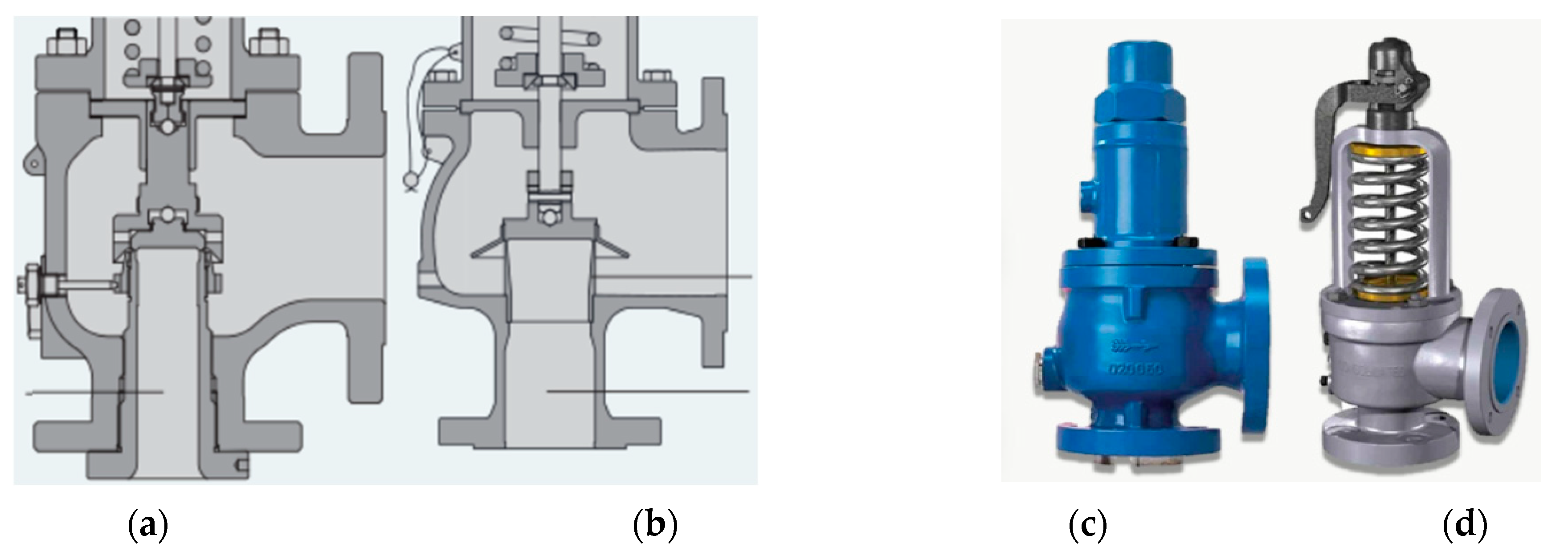
- (a)
- PRVs gradually open as the fluid pressure further exceeds the setpoint pressure whereas PSVs pop open once the setpoint pressure value is reached.
- (b)
- During operation, PRVs remain partially open, whereas PSVs cycle between being fully open and fully closed.
- (c)
- Last, PRVs are installed to prevent unnecessary opening of PSVs during pressure transients.
2. Aspects Related to Industrial Processes and Case Studies
2.1. PSV in High-Pressure Thermal–Hydraulic Experiments
2.2. PSV in Industrial Process and Power Plants
2.3. Case Studies: Plant-Level Accidents Due to PSV Failure
3. Terminology and Factors Related to PSV
- Pressure Relief Valves: PRVs are spring-loaded devices—characterized by a rapid opening, often proportional to the pressure, due to overpressure—that open when excess pressure is present and close when normal conditions have been restored.
- Relief Valves: Relief valves are pressure relief devices that are actuated by static pressure at the inlet and raise gradually when the opening pressure is exceeded. This device is primarily used for liquid service, and it contains a spring enclosure for closed discharge systems.
- Safety Relief Valves: These valves are used for liquid or compressible fluids and exhibit features like rapid opening, popping actions, or opening proportionally to the increased pressure.
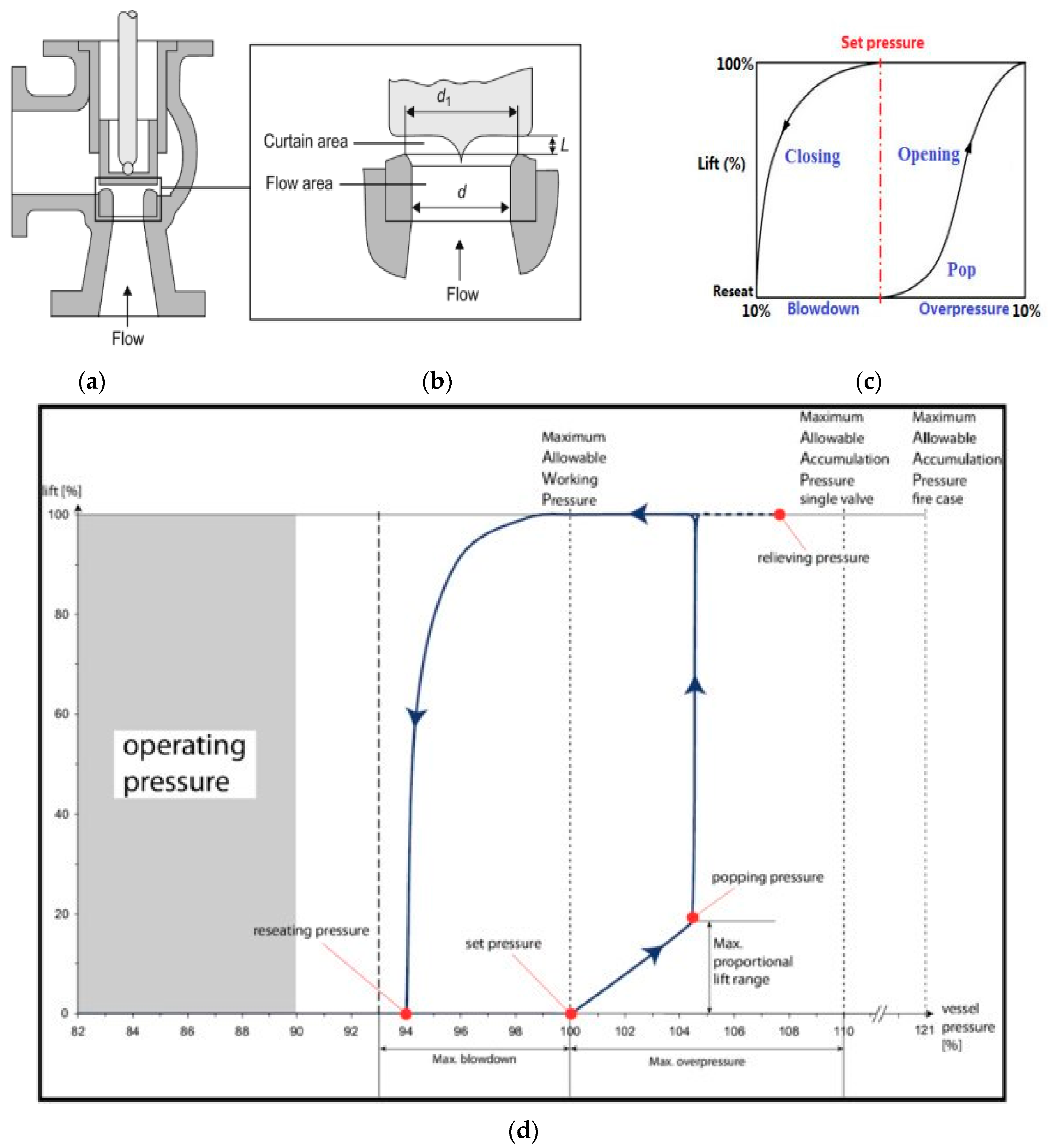
- Blowdown: The pressure difference between the PSV’s/PRV’s popping and reseating pressure, expressed as a percentage or pressure units.
- Popping pressure: The inlet static pressure causing the PSV/PRV disc to move faster in the opening direction, applicable to compressible fluids.
- Set pressure: The pressure at which a PSV/PRV starts relieving fluid, displaying opening, popping, or start-to-leak characteristics.
- Reseating: The closing of a PSV/PRV after normal operating conditions is restored, requiring pressure to drop below the set point.
- Accumulation: The pressure increase over a PSV’s/PRV’s set pressure, expressed as a percentage. A normal accumulation is 10% of the set pressure, 10% for compressible fluids, 3% for high-temperature fluid (steam), and 16% for multiple PSVs.
- Considering process data and parameters: The process data and parameters are prerequisites for selecting the valve type, orifice, and accessories. The required process parameters are the flow rate, pressure, temperature, fluid properties (such as density, viscosity, Cp/Cv), and service conditions.
- Orifice and valve selection: The selection of the orifice size is based on the minimum required flow rate using the valve capacity tables. Selection of the valve is based on the process temperature and pressure. Valve characteristics should be selected based on the required process control parameters.
- Options and accessories: Options and accessories like the rapture disc, rapture pin, and pilot-operated safety relief valve must be separately specified. In this study, safety relief valve sizing for vaporizing liquids (i.e., fire condition) is emphasized.
4. Sizing PSVs/PRVs for Vaporizing Liquids, Considering Fire Conditions
- Determine the total heat absorption and environmental safety factors: The calculation procedure and associated equations used to determine the total heat absorption and environmental safety factors are presented in Table 4.
- Determine the valve orifice size: The minimum area required is estimated, and the size of the orifice is selected from the manufacturer’s valve capacity table. The steps for valve orifice size estimation and correction factors are presented in Table 5.

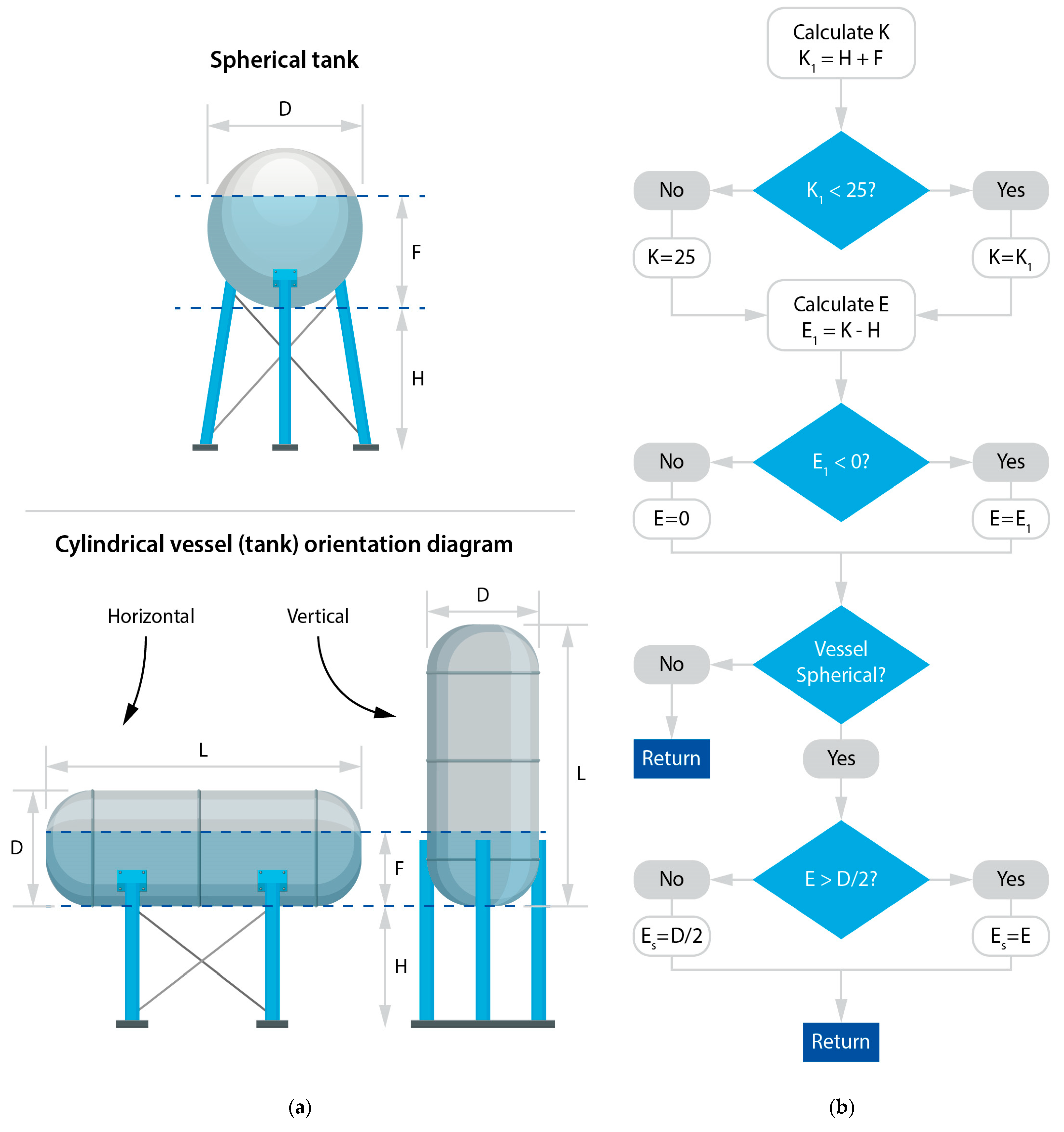
| PV Geometry | Wetted Surface Area, | Parameters |
|---|---|---|
| Sphere | , Total wetted area, . B, Effective liquid level angle, degrees. L, Vessel end-to-end length, . E, Effective liquid level, . , Effective spherical liquid level, . , Initial liquid level, . D, Vessel diameter, . K, Effective total height of the liquid surface, . , Height of the liquid surface, feet. H, Vessel elevation, . F, Liquid depth in the vessel, . | |
| H-cylinder with flat ends | ||
| H-cylinder with spherical ends | ||
| V-cylinder with flat ends | ||
| V-cylinder with spherical ends | ||
| Effective liquid level angle, degrees |

| Conditions (Prompt Firefighting and Adequate Drainage Options) | Total Heat Absorption, | Parameters |
|---|---|---|
| Available | , total wetted area, , total heat absorption, F, factor F based on vessel type | |
| Not available | ||
| Vessel type | Environmental factor, F (IC) | |
| Bare vessel | 1 | IC, insulation conductance values, |
| Insulated vessel, with IC value | 0.3 (4), 0.15 (2), 0.075 (1), 0.05 (0.67), 0.0376 (0.5), 0.03 (0.4), 0.026 (0.33) | |
| Water application facilities, on bare vessels, F =1 | ||
| Depressurizing and emptying facilities, F = 1 | ||
| Rate of vapor from liquid, W, | , latent heat, , rate of vapor from liquid | |
| Determine the fluid mass flow converted to gas from the liquid, | ||
| Orifice Area | Parameters | |
|---|---|---|
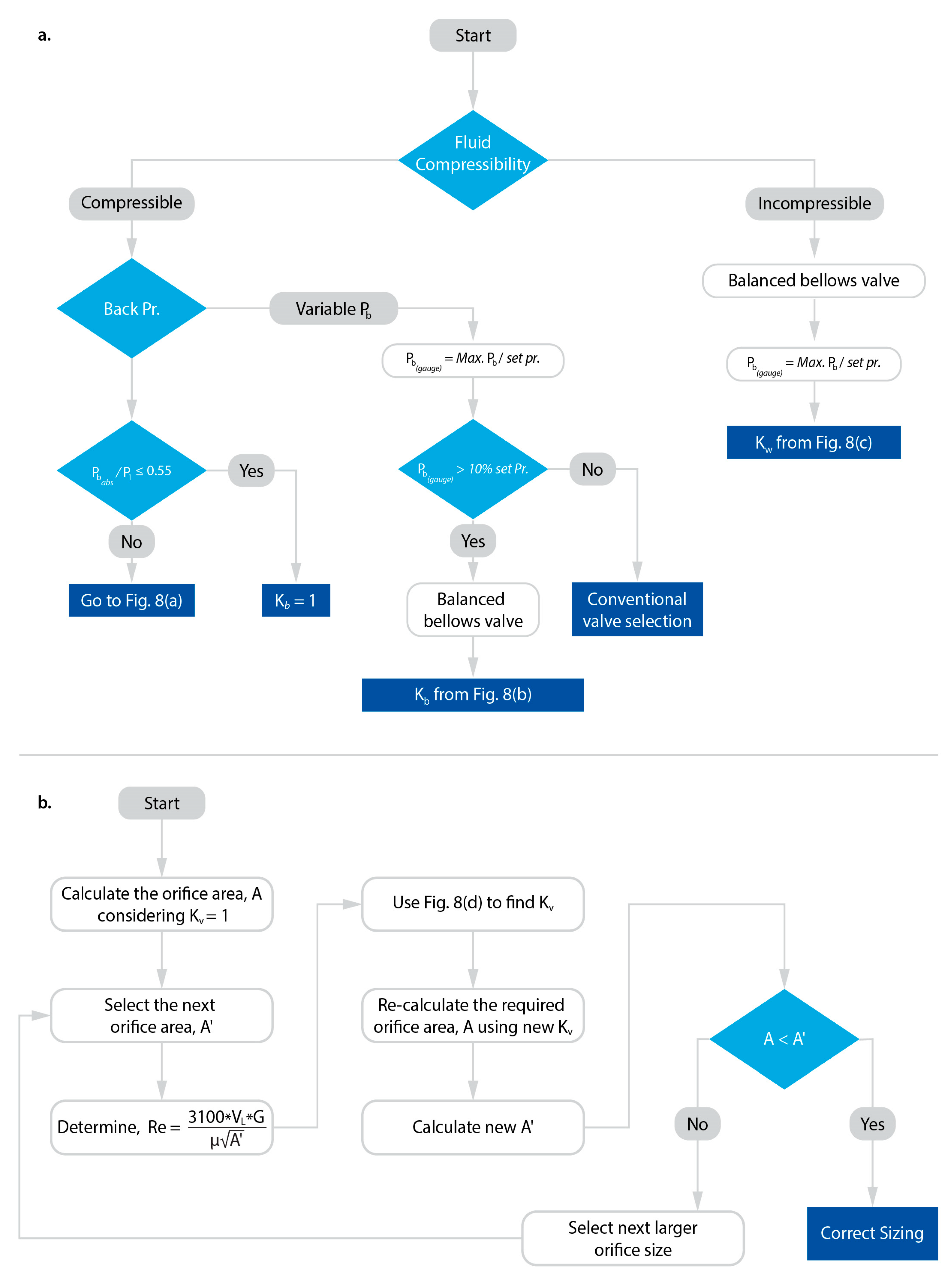
| General | Correction factors: , back pressure, , for superheated steam, , back pressure for liquids, , viscosity (for water, = 1), , for valves with uncertified, (for 10% o/v pr., = 0.6; for 15% o/v, = 0.8; and for 25% o/v pr. = 1), and , for Napier equation | |
| For gas or steam (kg/hr) | ||
| For steam (kg/hr) For liquid (m3/h) For air (Nm3/h) |
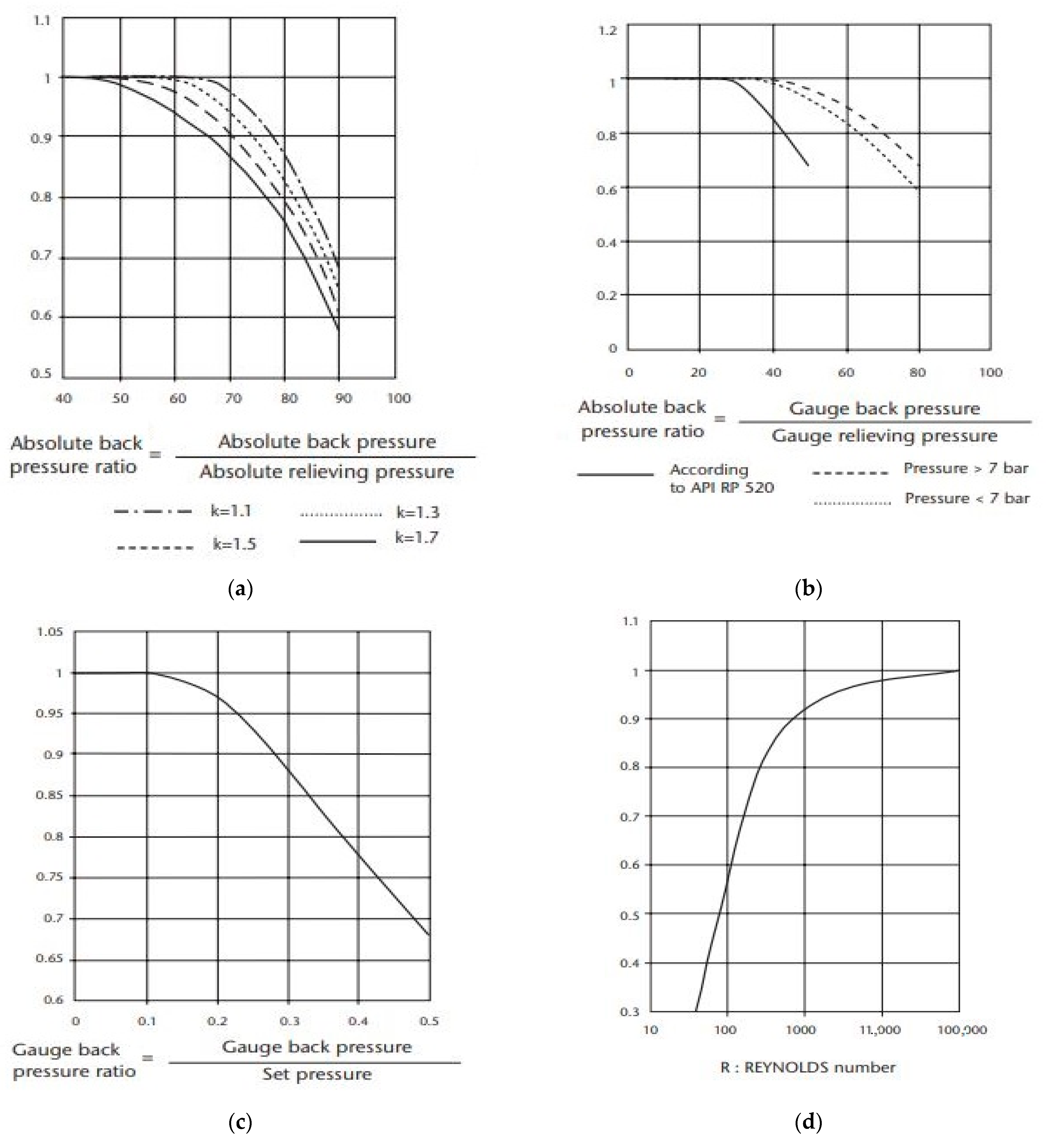
4.1. Calculate the Correction Factors
4.2. Selecting the Orifice Size and Valve Model
4.3. Case Studies: PSV Selection
| Relevant | Calculation | Parameters |
|---|---|---|
| Relieving pressure (absolute) | = set Pr. + over Pr. + atm. Pr. = 3.2 + (3.2 × 16%) + 1.013 Bar = 4.725 Bar | Gas, relieving fluid W = 50,000 kg/hr, required relieving capacity (each valve) M = 94 kg/k. Mole, molecular weight Z = 1, compressibility factor (If unknown, use Z = 1) T = 473 K, relieving temperature (absolute) C = 344, gas constant (specific heat ratio, k = 1.27) K = 0.975, flow factor (for gas and steam, K = 0.975) P = 3.2 bar, set pressure = 0, back pressure Use three PSVs for the application |
| Required number of PSVs is 3 | So, over pressure= 16% of set Pr From Figure 8, back pressure correction factor, = 1 | |
| Orifice area for gas or steam (kg/h) | = 93.1665 cm2 | |
| Next higher orifice size | from Table 6, = 103 cm2 | |
| Modified valve flow rate | A’/A × W = 55,277.4 kg/hr | |
| Using the Serasin-RSBD valve manufacturer, we select the valve model for the R orifice, with an orifice size of 103 cm2, a relieving temperature of 473K, and a set pressure of 3.2 bar as follows: The preliminary valve model: P68R1 6RB 150 lb; Dimensions: A (239.7), B (241.3); Inlet/outlet DN (6 in. × 150 lb/8 in. × 150 lb), Weight (215 kg), Valve type (conventional type because there is no back pressure).The final valve model is determined as P68R1 330 | ||
5. Testing and Servicing Procedures
5.1. Procedure for PSV Disassembly
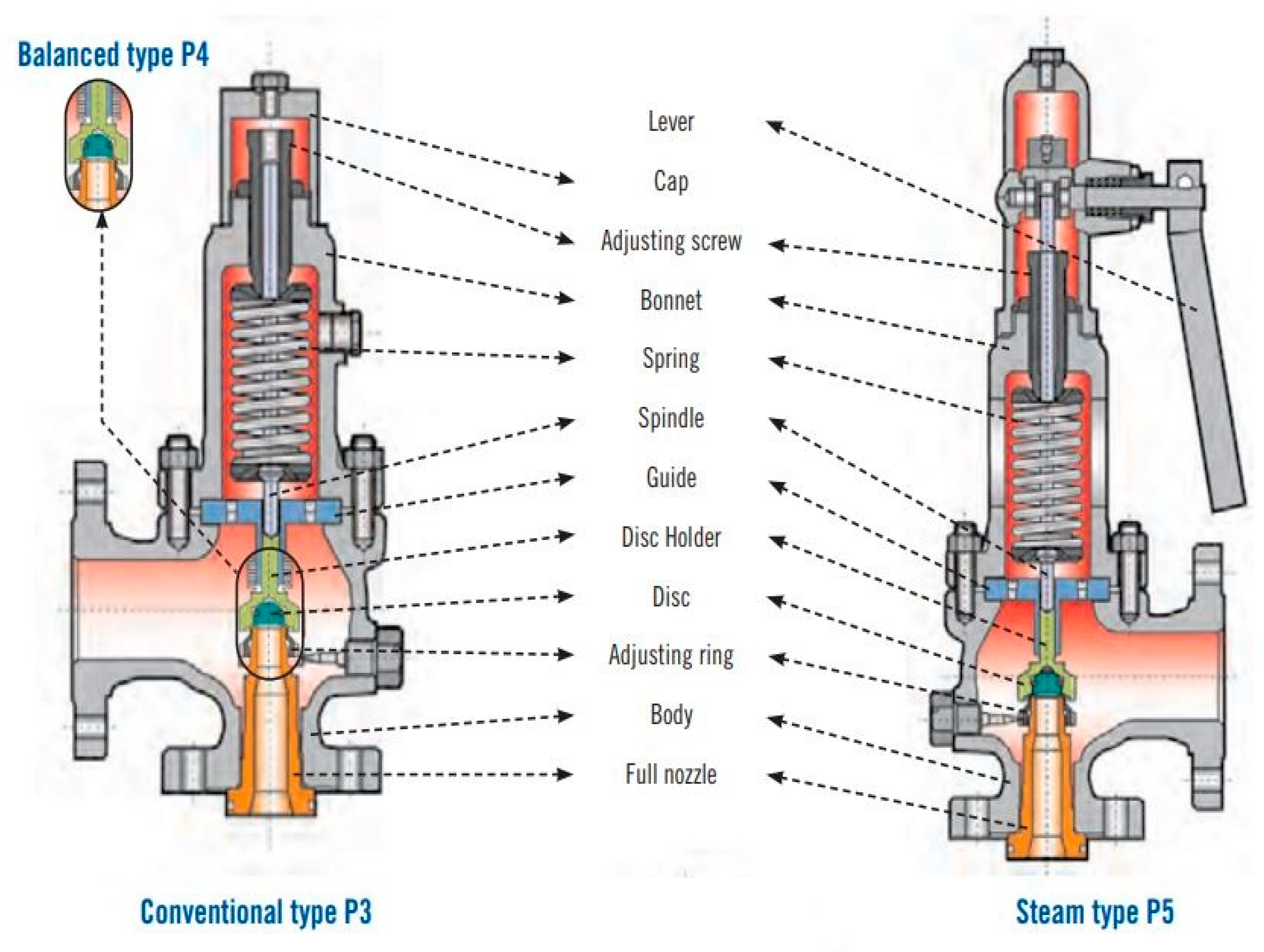
- Step 1: Remove the valve cap, note the length of the adjusting screws, loosen the locknut, and adjust the screw to remove the bonnet, spring, and spring washers.
- Step 2: Remove the spindle, ball, disc, and bellow. Loosen and unscrew the adjusting ring. Invert the valve body and dismantle the nozzle using drift.
5.2. Procedure for Servicing and Reassembly
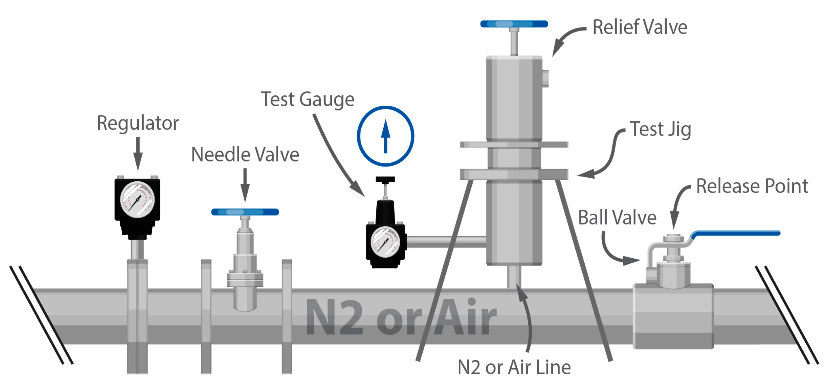
5.3. Procedure for PSV Testing and Servicing
- Step 1: Open the PSV from the process line with marking (e.g., inlet, outlet, blow line). Pre-test the PSV. If the first pre-test result is not satisfactory, test again.
- Step 2: Disassemble the PSV, clean, and service. Lap the nozzle. Assemble the PSV.
- Step 3: Test the PSV:
- ○
- Gradually increase the inlet pressure in the test bench. Outlet (blow line of PSV) pressure is measured by bubble formation in water. When static inlet Pr. ≥ set Pr. => Pop action, PSV will operate. After the blow, PSV will stop within a short time.
- ○
- If the operating pressure and set pressure differ, readjust the spring pressure/tension. If the operating point is the same in several test results and leakage is very low, the valve is ready for qualification testing.
- ○
- Keep a record of the pre-test, test, set pressure, and operating pressure in the record book signed by the inspector. If the spring performance degrades, changing the spring is recommended.
- ○
- In general, case ±10% accumulation is considered. For special PSVs, considering the process and test condition case, ±3% or ±16% accumulation is used.
- ○
- Because there is no option for giving back pressure, the bellows type PSV has to allow higher leakages. This leakage is compensated by the back pressure.
- ○
- After testing, PSVs should be sealed with the proper tag.
- Step 4: Seat tightness checking procedure:
- ○
- Make sure that the valve is properly installed and all connections are tight.
- ○
- Set the pressure at the valve inlet to the MAWP. Open the valve and allow it to discharge until the pressure drops to the set pressure. Repeat this process three to four times to ensure the valve has been fully exercised.
- ○
- After exercising the valve, reduce the pressure to 90% of the set pressure. Close the outlet of the valve and measure the leakage rate for one minute.
- ○
- If the valve has a metal seat, compare the leakage rate with the values given in Table 8 of API 527. The leakage rate should be within the desired value.
- ○
- If the leakage rate is within the acceptable limits, the valve is considered to be seat tight. Otherwise, the valve should be disassembled and inspected for any damage or wear. The seat and disc should be replaced if necessary.
- ○
- Reassemble the valve and repeat the seat tightness test. Once the valve passes the seat tightness test, it can be put back into service.
6. Conclusions
- Provides an overview of the PSV/PRV systems to support safety of the pressurized system.
- Defines and discusses the basic terminology related to PSV/PRV design and operation.
- Addresses the special design features and their pros and cons for specific process applications.
- Demonstrates standard procedures with associated equations and characteristic curves to size and select the suitable PSV/PRV for specific applications.
- Identifies that the major causes of PSV performance degradation are cavitation and wear, which are the root cause of disruption in fluid flow distribution/dynamics, boundary-layer formation and pressure drops across valve flow regions, gas bubble formation and collapse, variations in geometric configuration and the shape of components and inlet/outlet piping, and acoustic resonance.
- Examines a case study to show the correctness of the presented procedure to select and size a PSV/PRV with associated features that match with the original design model.
- Offers an outline of the servicing and testing of PSVs/PRVs, which is considered an industry standard and driven by proven practice.
Funding
Acknowledgments
Conflicts of Interest
Disclaimer
Abbreviations
| API | American Petroleum Institute |
| ASME | American Society of Mechanical Engineers |
| ISO | International Organization for Standardization |
| MAWP | maximum allowable working pressure |
| MP | megapascals |
| PSEP | process safety and environmental protection |
| PSV | pressure safety valve |
| PRV | pressure relief valve |
| Variables and Greek symbols | |
| A | flow area, [m2] |
| Awet | wetted surface area, [ft2] |
| B | effective liquid level angle, degrees |
| C | gas constant (Cp for constant pressure, and Cv for constant volume) |
| D | vessel diameter [ft] |
| E | effective liquid level [ft] |
| effective spherical liquid level [ft] | |
| initial liquid level [ft] | |
| F | liquid depth in vessel [ft] |
| F | environmental factor |
| G | density of a gas to air or liquid compared to water |
| H | vessel elevation [ft] |
| H_vap | latent heat, [Btu/lb] |
| IC | insulation conductance values, [Btu/(hr.ft2.F)] |
| K | effective total height of liquid surface [ft] |
| total height of liquid surface [ft] | |
| K | flow factor (for gas/steam, = 0.975, for liquid, = 0.70, for API 520, liquid, , = 0.62) |
| K | correction factor ( for constant back pressure and for variable back pressure) |
| L | vessel end-to-end length [ft] |
| M | molecular weight |
| relieving pressure (pr.) (abs) = set pr. + over pr.+ 1.013 | |
| P | set pressure |
| Pr | pressure |
| back pressure | |
| total heat absorption [Btu/hr] | |
| T | relieving temperature, absolute |
| V | required capacity, [Nm2/hr] |
| VL | required capacity, [m3/hr] |
| rate of vapor from liquid [lbs/hr] | |
| compressibility factor, if unknown, use =1 | |
| k | specific heat ratio, k = /, if unknown, use k = 1.001 |
| Subscript: b-back pressure, w-variable break pressure, and L-liquid | |
References
- Sotoodeh, K. The Design of Pressure Safety and Relief Valves for Overpressure Protection: Essential considerations. Trans. Indian Natl. Acad. Eng. 2023, 8, 273–287. [Google Scholar] [CrossRef]
- ASME. BPVC-VIII-1—Section VIII Division 1 Rules for Construction of Pressure Vessels; American Society of Mechanical Engineers: New York, NY, USA, 2022. [Google Scholar]
- ASME BPVC. Boiler and Pressure Vessel Code (BPVC); Section I & VIII; American Society of Mechanical Engineers (ASME): New York, NY, USA, 2022. [Google Scholar]
- ASME PTC-25; Performance Test Codes Standards Committee, Pressure Relief Devices. American Society of Mechanical Engineers: New York, NY, USA, 2022.
- API 520; Sizing, Selection, and Installation of Pressure-Relieving Devices, Sixth Edition. American Petroleum Institute: Washington, DC, USA, 2022.
- API STD 521; Pressure-Relieving and Depressuring Systems. American Petroleum Institute (API): Washington, DC, USA, 2022.
- API RP 520; Recommended Practice for the Design and Construction of Pressure Relieving Systems in Refineries, Sixth Edition. American Petroleum Institute: Washington, DC, USA, 2022.
- API 527; Seat Tightness of Pressure Relief Valves, Fourth Edition. American Petroleum Institute: Washington, DC, USA, 2022.
- Crowl, D.A.; Tipler, S.A. Sizing pressure-relief devices. Chem. Eng. Prog. 2013, 109, 68–76. [Google Scholar]
- Signoret, J.P.; Leroy, A. Reliability Assessment of Safety and Production Systems: Analysis, Modelling, Calculations and Case Studies; Springer Nature: Berlin/Heidelberg, Germany, 2021. [Google Scholar]
- Bhowmik, P.K. Sizing and selection of pressure relief safety valve. In Proceedings of the 6th International Mechanical Engineering Conference & 14th Annual Paper Meet (6IMEC&14APM), Dhaka, Bangladesh, 28–29 September 2012. [Google Scholar]
- Bhowmik, P.K.; Shamim, J.A.; Sabharwall, P. A review on the sizing and selection of control valves for thermal hydraulics for reactor system applications. Prog. Nucl. Energy 2023, 164, 104887. [Google Scholar] [CrossRef]
- Dempster, W.; Taggart, S.; Doyle, C. Limitations in the use of pressure scaling for safety relief valve design. In Pressure Vessels and Piping Conference; American Society of Mechanical Engineers: New York, NY, USA, 2018; Volume 51623, p. V03AT03A002. [Google Scholar]
- Hellemans, M. The Safety Relief Valve Handbook: Design and Use of Process Safety Valves to ASME and International Codes and Standards; Elsevier: Amsterdam, The Netherlands, 2009. [Google Scholar]
- Kerr, T.A.; Myers, D.B.; Piggott, B.D.; Vance, A.E. Solving Pressure Relief Valve and Piping Capacity Problems. 2018. Available online: http://trimeric.com/assets/solving-pressure-relief-valve-and-piping-capacity-problems-rev-1.pdf (accessed on 1 October 2023).
- Hős, C.; Bazsó, C.; Champneys, A. Model reduction of a direct spring-loaded pressure relief valve with upstream pipe. IMA J. Appl. Math. 2014, 80, 1009–1024. [Google Scholar] [CrossRef]
- Bhowmik, P.K.; Suh, K.Y. Flow mapping using 3D full-scale CFD simulation and hydrodynamic experiments of an ultra-supercritical turbine’s combined valve for nuclear power plant. Int. J. Energy Environ. Eng. 2021, 12, 365–381. [Google Scholar] [CrossRef]
- Beune, A. Analysis of High-Pressure Safety Valves. Ph.D. Thesis, Eindhoven University of Technology, Eindhoven, Netherlands, 2009. [Google Scholar]
- Moktadir, M.A.; Ali, S.M.; Kusi-Sarpong, S.; Shaikh, M.A.A. Assessing challenges for implementing Industry 4.0: Implications for process safety and environmental protection. Process Saf. Environ. Prot. 2018, 117, 730–741. [Google Scholar] [CrossRef]
- De Rademaeker, E.; Suter, G.; Pasman, H.J.; Fabiano, B. A review of the past, present and future of the European loss prevention and safety promotion in the process industries. Process. Saf. Environ. Prot. 2014, 92, 280–291. [Google Scholar] [CrossRef]
- Belles, R.J. Key reactor system components in integral pressurized water reactors (iPWRs). In Handbook of Small Modular Nuclear Reactors; Woodhead Publishing: Sawston, UK, 2021; pp. 95–115. [Google Scholar]
- Bhowmik, P.K. Nanofluid Operation and Valve Engineering of SUPER for Small Unit Passive Enclosed Reactor. Master’s Thesis, Department of Nuclear Engineering, Seoul National University, Seoul, Republic of Korea, 2016. [Google Scholar]
- Wang, M.; Qiu, S.; Su, G.; Tian, W. Research on the leak-rate characteristics of leak-before-break (LBB) in pressurized water reactor (PWR). Appl. Therm. Eng. 2014, 62, 133–140. [Google Scholar] [CrossRef]
- Bae, B.U.; Lee, J.B.; Park, Y.S.; Kim, J.; Kang, K.H. Experimental investigation on thermal hydraulic interaction of RCS (reactor coolant system) and containment for intermediate break loss-of-coolant accident (IBLOCA) scenario in AT-LAS-CUBE test facility. Prog. Nucl. Energy 2022, 146, 104156. [Google Scholar] [CrossRef]
- Galbally, D.; García, G.; Hernando, J.; Sánchez, J.d.D.; Barral, M. Analysis of pressure oscillations and safety relief valve vibrations in the main steam system of a Boiling Water Reactor. Nucl. Eng. Des. 2015, 293, 258–271. [Google Scholar] [CrossRef]
- Oh, K.S.; Jeong, E.; Shim, W.S.; Baek, J.B. The Effectiveness of Pressure Safety Valves in Chemical Supply Systems to Prevent Fire, Explosion, and Overpressure in the Korean Semiconductor Industry. Fire 2023, 6, 344. [Google Scholar] [CrossRef]
- Schmidt, J. Sizing of safety valves for multi-purpose plants according to ISO 4126-10. J. Loss Prev. Process. Ind. 2012, 25, 181–191. [Google Scholar] [CrossRef]
- Ade, N.; Liu, G.; Al-Douri, A.F.; El-Halwagi, M.M.; Mannan, M.S. Investigating the effect of inherent safety principles on system reliability in process design. Process. Saf. Environ. Prot. 2018, 117, 100–110. [Google Scholar] [CrossRef]
- Bhowmik, P.K.; Perez, C.E.E.; Fishler, J.D.; Prieto, S.A.B.; Reichow, I.D.; Johnson, J.T.; Sabharwall, P.; O’Brien, J.E. Integral and Separate Effects Test Facilities To Support Water Cooled Small Modular Reactors: A Review. Prog. Nucl. Energy 2023, 160, 104697. [Google Scholar] [CrossRef]
- Yang, L.; Wang, Z.; Dempster, W.; Yu, X.; Tu, S.-T. Experiments and transient simulation on spring-loaded pressure relief valve under high temperature and high pressure steam conditions. J. Loss Prev. Process. Ind. 2017, 45, 133–146. [Google Scholar] [CrossRef]
- NUREG-0800; Standard Review Plan for the Review of Safety Analysis Reports for Nuclear Power Plants: LWR Edition (NUREG-0800, Formerly issued as NUREG-75/087). U.S. Nuclear Regulatory Commission (USNRC): Rockville, MD, USA, 2008.
- Mengjie, Z.; Biao, H.; Zhongdong, Q.; Taotao, L.; Qin, W.; Hanzhe, Z.; Guoyu, W. Cavitating flow structures and corre-sponding hydrodynamics of a transient pitching hydrofoil in different cavitation regimes. Int. J. Multiph. Flow 2020, 132, 103408. [Google Scholar] [CrossRef]
- Ou, G.; Xu, J.; Li, W.; Chen, B. Investigation on cavitation flow in pressure relief valve with high pressure differentials for coal liquefaction. Procedia Eng. 2015, 130, 125–134. [Google Scholar] [CrossRef]
- Tandiono, T.; Kang, C.W.; Lu, X.; Turangan, C.K.; Tan, M.; Bin Osman, H.; Lim, F. An experimental study of gas nuclei-assisted hydrodynamic cavitation for aquaculture water treatment. J. Vis. 2020, 23, 863–872. [Google Scholar] [CrossRef]
- Soares, A.K.; Martins, N.M.C.; Covas, D.I.C. Transient vaporous cavitation in a horizontal copper pipe. J. Hydraul. Res. 2017, 55, 731–736. [Google Scholar] [CrossRef]
- Rajasekar, J.; Kim, T.H.; Kim, H.D. Visualization of shock wave propagation due to underwater explosion. J. Vis. 2020, 23, 825–837. [Google Scholar] [CrossRef]
- Sharma, A.K.; Kumar, N.; Das, A.K. Cavitation analysis in a re-designed direct acting pressure relief valve through flow visualization method. J. Vis. 2023, 26, 1299–1319. [Google Scholar] [CrossRef]
- Yang, Q.; Aung, N.Z.; Li, S. Confirmation on the effectiveness of rectangle-shaped flapper in reducing cavitation in flapper–nozzle pilot valve. Energy Convers. Manag. 2015, 98, 184–198. [Google Scholar] [CrossRef]
- Han, M.; Liu, Y.; Wu, D.; Zhao, X.; Tan, H. A numerical investigation in characteristics of flow force under cavitation state inside the water hydraulic poppet valves. Int. J. Heat Mass Transf. 2017, 111, 1–16. [Google Scholar] [CrossRef]
- Kang, J.; Tang, Y. Dynamic cavitation in soft solids under monotonically increasing pressure. Int. J. Mech. Sci. 2021, 209, 106730. [Google Scholar] [CrossRef]
- Hős, C.J.; Champneys, A.R.; Paul, K.; McNeely, M. Dynamic behavior of direct spring loaded pressure relief valves in gas service: Model development, measurements, and instability mechanisms. J. Loss Prev. Process Ind. 2014, 31, 70–81. [Google Scholar] [CrossRef]
- Zheng, F.; Zong, C.; Zhang, C.; Song, X.; Qu, F.; Dempster, W. Dynamic Instability Analysis of a Spring-Loaded Pressure Safety Valve Connected to a Pipe by Using Computational Fluid Dynamics Methods. J. Press. Vessel. Technol. 2021, 143, 041403. [Google Scholar] [CrossRef]
- Izuchi, H.; Swindell, R.; Mann, A. Combining Acoustic Induced Vibration and Flow Induced Vibration. In Pressure Vessels and Piping Conference; American Society of Mechanical Engineers: New York, NY, USA, 2022; Volume 86168, p. V003T04A010. [Google Scholar]
- Johnston, D.N.; Edge, K.A.; Brunelli, M. Impedance and Stability Characteristics of a Relief Valve. Proc. Inst. Mech. Eng. 2002, 216, 371–382. [Google Scholar]
- Khan, F.I.; Abbasi, S.A. Major accidents in process industries and an analysis of causes and consequences. J. Loss Prev. Process. Ind. 1999, 12, 361–378. [Google Scholar] [CrossRef]
- Abdolhamidzadeh, B.; Abbasi, T.; Rashtchian, D.; Abbasi, S. Domino effect in process-industry accidents—An inventory of past events and identification of some patterns. J. Loss Prev. Process. Ind. 2011, 24, 575–593. [Google Scholar] [CrossRef]
- Chang, J.I.; Lin, C.C. A study of storage tank accidents. J. Loss Prev. Process Ind. 2006, 19, 51–59. [Google Scholar] [CrossRef]
- Shareefdeen, Z.; Bhojwani, J. Hazardous waste accidents: From the past to the present. In Hazardous Waste Management: Advances in Chemical and Industrial Waste Treatment and Technologies; Springer Nature: Berlin/Heidelberg, Germany, 2022; pp. 27–56. [Google Scholar]
- Tamim, N.; Scott, S.; Zhu, W.; Koirala, Y.; Mannan, M.S. Roles of contractors in process safety. J. Loss Prev. Process. Ind. 2017, 48, 358–366. [Google Scholar] [CrossRef]
- Leveson, N. Safety III: A systems approach to safety and resilience. MIT Eng. Syst. Lab 2020, 16, 2021. [Google Scholar]
- SERASIN RSBD, Sarasin RSBD Starflow Brochure, SRV-S-8-1012, Full-version, Trillium Flow Technologies 2020. Available online: https://trilliumflow.com/wp-content/uploads/2019/10/Sarasin-RSBD-Starflow-Brochure-SRV-S-8-1012-Full-version.pdf (accessed on 1 October 2023).
- Emerson. Pressure Relief Valve Engineering Handbook; Anderson Greenwood, Crosby and Varec products, Technical publication; Emerson: St. Louis, MI, USA, 2012; No. TP-V300. [Google Scholar]
- LESER. Safety Valve Handbook, Product Catalogue. 2023. Available online: https://www.leser.com/en-us/products/spring-loaded-pressure-relief-valves/ (accessed on 1 October 2023).
- SPIRAX SARCO. Safety Valves. 2023. Available online: https://www.spiraxsarco.com/learn-about-steam/safety-valves/safety-valves (accessed on 1 October 2023).
- Emerson. Pressure Relief Valves Product Overview, VCPBR-08579-EN 20/04. 2020. Available online: https://www.emerson.com/documents/automation/product-brochure-pressure-relief-valves-product-overview-europe-anderson-greenwood-crosby-marston-sempell-en-en-6001990.pdf (accessed on 1 October 2023).
- PIPING Mart. What Is the Process Of PSV Testing Popping Test Methods and PSV Calibration? 2022. Available online: https://blog.thepipingmart.com/other/what-is-the-process-of-psv-testing-popping-test-methods-and-psv-calibration/ (accessed on 1 October 2023).


| Facility and Location | Date | Incident/Accident Description | Key Root Causes |
|---|---|---|---|
| Petrochemical factory, Texas City, USA [47] | 30 May 1978 | An overpressure event in an LPG storage vessel during filling; the vessel cracked, resulting in an LPG leak. The leaked LPG ignited, creating a massive fireball. The explosion shattered the vessel and damaged two adjacent vessels. | A pressure gauge and a relief valve malfunctioned. This led to an overpressure event. |
| Petrochemical, Icmesa Chemical Company at Seveso [48] | 10 July 1976 | Explosion at a chemical process plant contaminated two square miles of crops and vegetables. | An overpressure event occurred, and the PSV on a reactor vented as a result. |
| Phillips explosion, Pasadena, Texas [49] | 23 October 1989 | Explosion, resulting in 23 fatalities. Primary causes of the accident included the (a) absence of process hazard analysis and human factor considerations and (b) insufficient operating and isolation procedures. | Incorrect connection of the actuating signal made the valve open when it should have been closed. |
| Petrochemical, Thunder Horse PDQ Tilting, Gulf of Mexico [49] | 11 July 2005 | The main cause of the incident was the uncontrolled water flow due to Hurricane Dennis. Water moved uncontrollably between several ballast tanks. | Incorrect valve positioning and operational mistakes triggered the event. |
| Petrochemical, T2 Laboratories Explosion in Jacksonville, Florida [49] | 19 December 2007 | The cooling system malfunctioned. This led to an uncontrolled chemical reaction while producing a gasoline additive. | The main issue was traced back to the poor design of the cooling and pressure relief systems. |
| Special Design Features | Applicability |
|---|---|
| Open Bonnet | If the process fluid has a high temperature and is non-hazardous, an open bonnet is generally used to prevent spring expansion. |
| Closed Bonnet | If process fluid is hazardous, a closed bonnet is used. |
| Full-Nozzle | This is suitable for high-pressure and corrosive fluid applications. |
| Semi-Nozzle | This design offers only the replacement of the seat instead of a full inlet. |
| Bellows | This is used when the back pressure of the process to PSVs is considered. |
| Orifice Area | D | E | F | G | H | J | K | L |
|---|---|---|---|---|---|---|---|---|
| Area (cm2) | 0.71 | 1.26 | 1.98 | 3.24 | 5.06 | 8.3 | 11.86 | 18.41 |
| Orifice Area | M | N | P | Q | R | T | V | W |
| Area (cm2) | 23.2 | 28 | 41.2 | 71.2 | 103 | 168 | 271 | 406 |
| Set Pressure | Leakage Rate for Effective Orifice Size, A [in2] (F Orifice) (Bubbles/min) | ||
|---|---|---|---|
| PSI (G) | Kg/cm2 (G) | A <= 0.307 in2 | A > 0.307 in2 |
| 15–1000 | 1–70 | 40 | 20 |
| 1500 | 105 | 60 | 30 |
| 2000 | 141 | 80 | 40 |
| 2500 | 176 | 100 | 50 |
| 3000 | 211 | 100 | 60 |
| 4000 | 281 | 100 | 80 |
| 5000 | 352 | 100 | 100 |
| 6000 | 422 | 100 | 100 |
Disclaimer/Publisher’s Note: The statements, opinions and data contained in all publications are solely those of the individual author(s) and contributor(s) and not of MDPI and/or the editor(s). MDPI and/or the editor(s) disclaim responsibility for any injury to people or property resulting from any ideas, methods, instructions or products referred to in the content. |
© 2023 by the authors. Licensee MDPI, Basel, Switzerland. This article is an open access article distributed under the terms and conditions of the Creative Commons Attribution (CC BY) license (https://creativecommons.org/licenses/by/4.0/).
Share and Cite
Bhowmik, P.K.; Sabharwall, P. Sizing and Selection of Pressure Relief Valves for High-Pressure Thermal–Hydraulic Systems. Processes 2024, 12, 21. https://doi.org/10.3390/pr12010021
Bhowmik PK, Sabharwall P. Sizing and Selection of Pressure Relief Valves for High-Pressure Thermal–Hydraulic Systems. Processes. 2024; 12(1):21. https://doi.org/10.3390/pr12010021
Chicago/Turabian StyleBhowmik, Palash K., and Piyush Sabharwall. 2024. "Sizing and Selection of Pressure Relief Valves for High-Pressure Thermal–Hydraulic Systems" Processes 12, no. 1: 21. https://doi.org/10.3390/pr12010021
APA StyleBhowmik, P. K., & Sabharwall, P. (2024). Sizing and Selection of Pressure Relief Valves for High-Pressure Thermal–Hydraulic Systems. Processes, 12(1), 21. https://doi.org/10.3390/pr12010021