
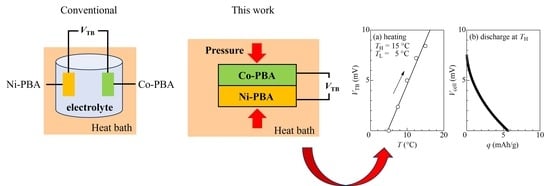
An Electrolyte-Free Thermo-Rechargeable Battery Made of Prussian Blue Analog Thin Films


Abstract
1. Introduction
2. Materials and Methods
2.1. Materials
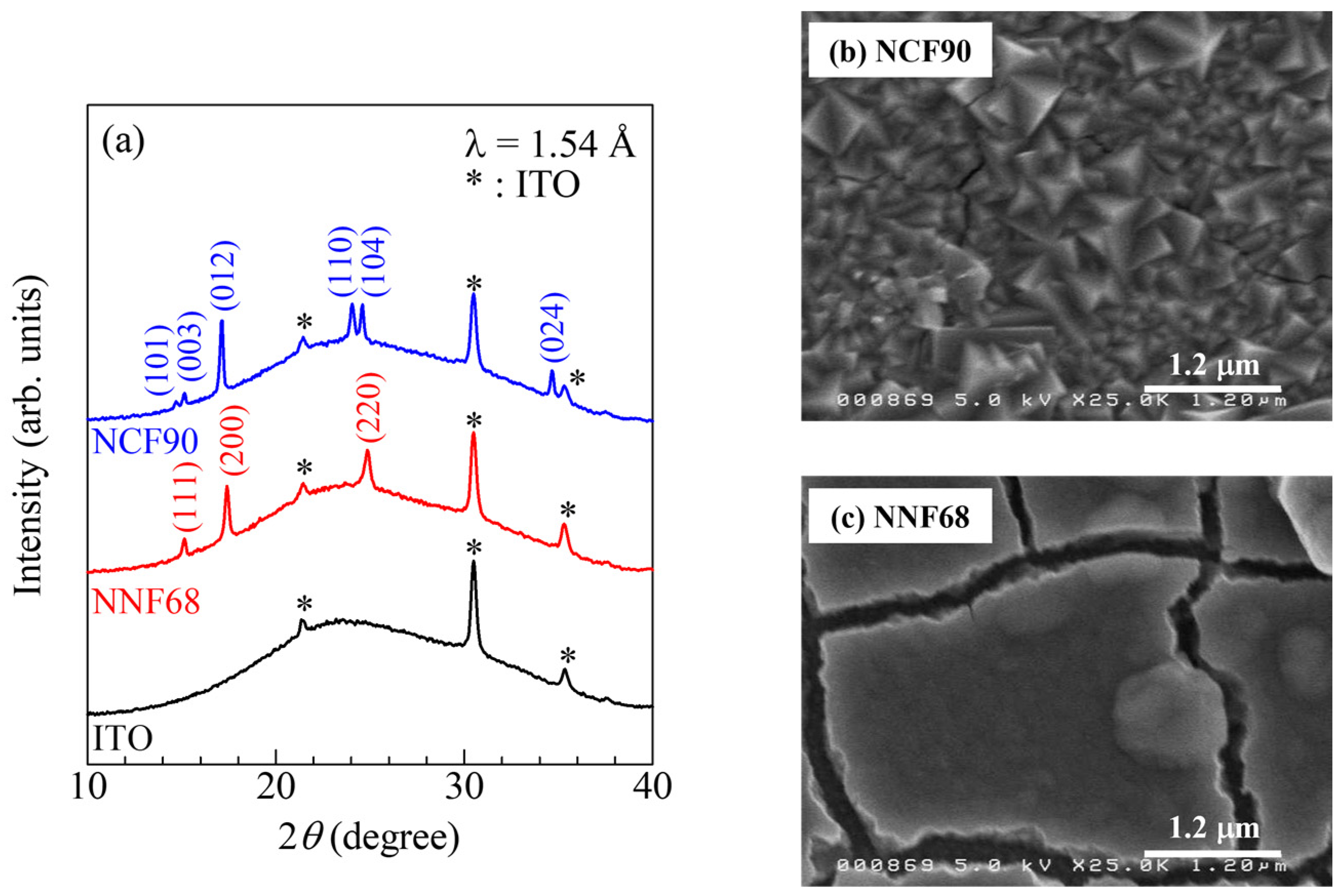
2.2. Sample Preparation and Characterization
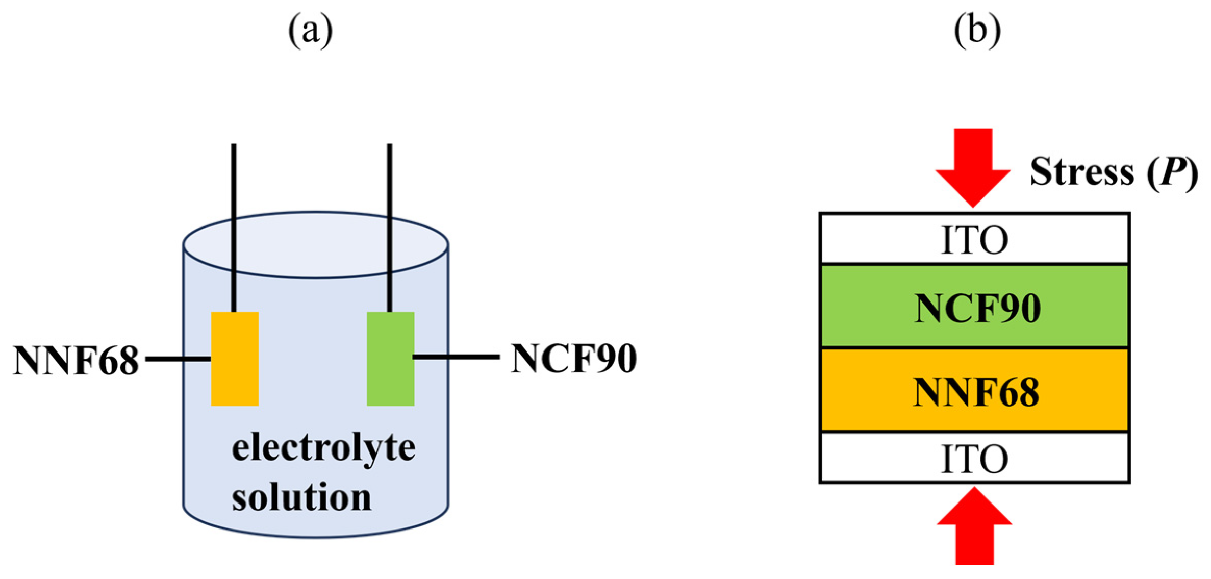
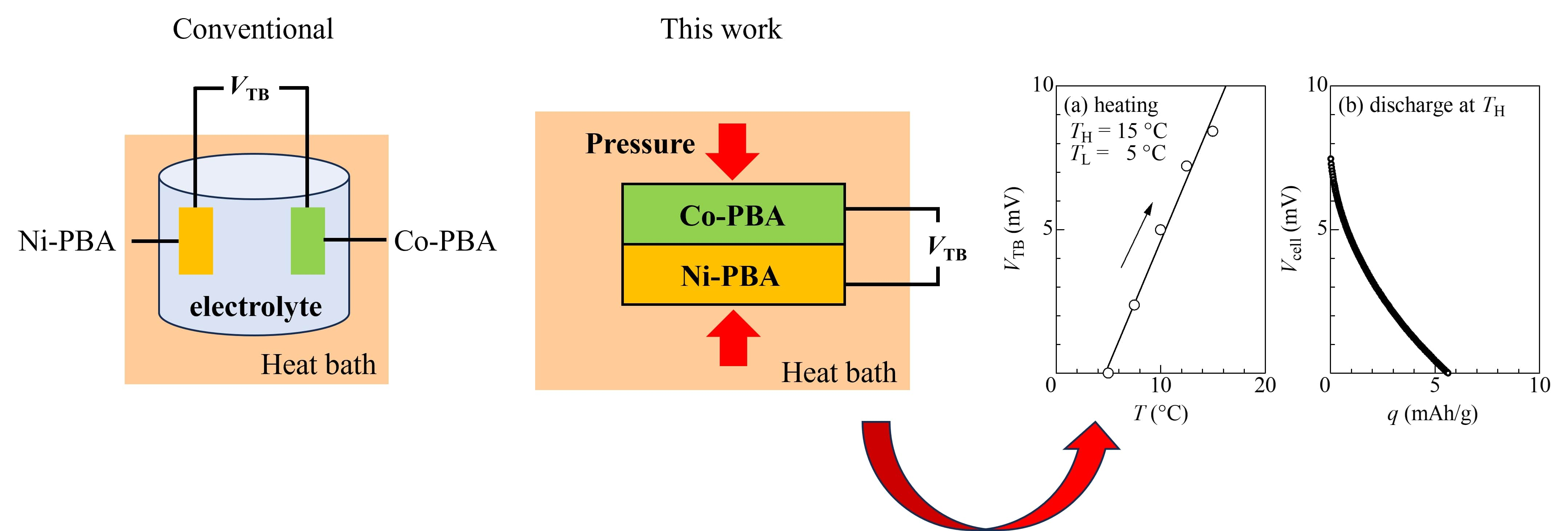
2.3. Electrolyte-Free Tertiary Battery Assembly
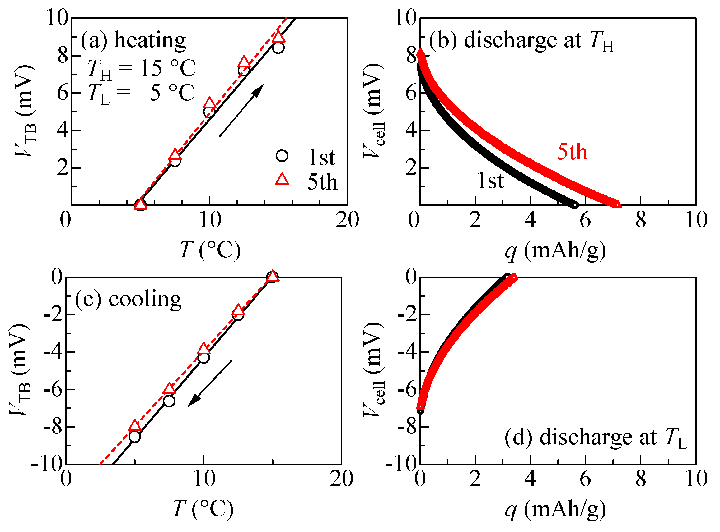
2.4. Thermal Cycle Measurement
3. Results and Discussion
4. Conclusions
Author Contributions
Funding
Data Availability Statement
Acknowledgments
Conflicts of Interest
References
- Lee, S.W.; Yang, Y.; Lee, H.-W.; Ghasemi, H.; Kraemer, D.; Chen, G.; Cui, Y. An electrochemical system for efficiently harvesting low-grade heat energy. Nat. Commun. 2014, 5, 3942. [Google Scholar] [CrossRef]
- Yang, Y.; Lee, S.W.; Ghasemi, H.; Loomis, J.; Li, X.; Kraemer, D.; Zheng, G.; Cui, Y.; Chen, G. Charging-free electrochemical system for harvesting low-grade thermal energy. Proc. Natl. Acad. Sci. USA 2014, 111, 17011–17016. [Google Scholar] [CrossRef]
- Wang, J.; Feng, S.-P.; Yang, Y.; Hau, N.Y.; Munro, M.; Ferreira-Yang, E.; Chen, G. “Thermal Charging” Phenomenon in Electrical Double Layer Capacitors. Nano Lett. 2015, 15, 5784–5790. [Google Scholar] [CrossRef]
- Gao, C.; Lee, S.W.; Yang, Y. Thermally Regenerative Electrochemical Cycle for Low-Grade Heat Harvesting. ACS Energy Lett. 2017, 2, 2326–2334. [Google Scholar] [CrossRef]
- Shibata, T.; Fukuzumi, Y.; Kobayashi, W.; Moritomo, Y. Thermal power generation during heat cycle near room temperature. Appl. Phys. Express 2018, 11, 017101. [Google Scholar] [CrossRef]
- Fukuzumi, Y.; Amaha, K.; Kobayashi, W.; Niwa, H.; Moritomo, Y. Prussian Blue Analogues as Promising Thermal Power Generation Materials. Energy Technol. 2018, 6, 1865–1870. [Google Scholar] [CrossRef]
- Shibata, T.; Fukuzumi, Y.; Moritomo, Y. Thermal efficiency of a thermocell made of Prussian blue analogues. Sci. Rep. 2018, 8, 14784. [Google Scholar] [CrossRef]
- Takahara, I.; Shibata, T.; Fukuzumi, Y.; Moritomo, Y. Improved Thermal Cyclability of Tertiary Battery Made of Prussian Blue Analogues. ChemistrySelect 2019, 4, 8558–8563. [Google Scholar] [CrossRef]
- Shibata, T.; Iwaizumi, H.; Fukuzumi, Y.; Moritomo, Y. Energy harvesting thermocell with use of phase transition. Sci. Rep. 2020, 10, 1813. [Google Scholar] [CrossRef]
- Shibata, T.; Nakamura, K.; Nozaki, S.; Iwaizumi, H.; Ohnuki, H.; Moritomo, Y. Optimization of electrode parameters of NaxCo[Fe(CN)6]0.88/NaxCd[Fe(CN)6]0.99 tertiary battery. Sustain. Mater. Technol. 2022, 33, e00483. [Google Scholar]
- Li, X.; Li, J.; Yun, J.; Wu, A.; Gao, C.; Lee, S.W. Continuous thermally regenerative electrochemical systems for directly converting low-grade heat to electricity. Nano Energy 2022, 101, 107547. [Google Scholar] [CrossRef]
- Wu, A.; Li, X.; Lee, D.; Li, J.; Yun, J.; Jiang, C.; Li, Z.; Lee, S.W. Thermoresponsive ionic liquid for electrochemical low-grade heat harvesting. Nano Energy 2023, 105, 108022. [Google Scholar] [CrossRef]
- Choi, A.; Song, Y.-Y.; Kim, J.; Kim, D.; Kim, M.-H.; Lee, S.W.; Seo, D.-H.; Lee, H.-W. Enhancing Efficiency of Low-Grade Heat Harvesting by Structural Vibration Entropy in Thermally Regenerative Electrochemical Cycles. Adv. Mater. 2023, 35, 2303199. [Google Scholar] [CrossRef]
- Atkins, P.; De Paula, J. Elements of Physical Chemistry, 7th ed.; Oxford University Press: Oxford, UK, 2017. [Google Scholar]
- Buser, H.J.; Schwarzenbach, D.; Petter, W.; Ludi, A. The crystal structure of Prussian Blue: Fe4[Fe(CN)6]3∙xH2O. Inorg. Chem. 1977, 16, 2704–2710. [Google Scholar] [CrossRef]
- Herren, F.; Fischer, P.; Ludi, A.; Haelg, W. Neutron diffraction study of Prussian Blue, Fe4[Fe(CN)6]3∙xH2O. Location of water molecules and long-range magnetic order. Inorg. Chem. 1980, 19, 956–959. [Google Scholar] [CrossRef]
- Niwa, H.; Kobayashi, W.; Shibata, T.; Nitani, H.; Moritomo, Y. Invariant nature of substituted element in metal-hexacyanoferrate. Sci. Rep. 2017, 7, 13225. [Google Scholar] [CrossRef] [PubMed]
- Imanishi, N.; Morikawa, T.; Kondo, J.; Takeda, Y.; Yamamoto, O.; Kinugasa, N.; Yamagishi, T. Lithium intercalation behavior into iron cyanide complex as positive electrode of lithium secondary battery. J. Power Sources 1999, 79, 215–219. [Google Scholar] [CrossRef]
- Imanishi, N.; Morikawa, T.; Kondo, J.; Yamane, R.; Takeda, Y.; Yamamoto, O.; Sakaebe, H.; Tabuchi, M. Lithium intercalation behavior of iron cyanometallates. J. Power Sources 1999, 81–82, 530–534. [Google Scholar] [CrossRef]
- Okubo, M.; Asakura, D.; Mizuno, Y.; Kim, J.-D.; Mizokawa, T.; Kudo, T.; Honma, I. Switching Redox-Active Sites by Valence Tautomerism in Prussian Blue Analogues AxMny[Fe(CN)6]·nH2O (A: K, Rb): Robust Frameworks for Reversible Li Storage. J. Phys. Chem. Lett. 2010, 1, 2063–2071. [Google Scholar] [CrossRef]
- Matsuda, T.; Moritomo, Y. Thin Film Electrode of Prussian Blue Analogue for Li-ion Battery. Appl. Phys. Express 2011, 4, 047101. [Google Scholar] [CrossRef]
- Takachi, M.; Matsuda, T.; Moritomo, Y. Structural, Electronic, and Electrochemical Properties of LixCo[Fe(CN)6]0.902.9H2O. Jpn. J. Appl. Phys. 2013, 52, 044301. [Google Scholar] [CrossRef]
- Shen, L.; Wang, Z.; Chen, L. Prussian Blues as a Cathode Material for Lithium Ion Batteries. Chem. Eur. J. 2014, 20, 12559–12562. [Google Scholar] [CrossRef] [PubMed]
- Shi, D.-R.; Fu, J.; Shadike, Z.; Cao, M.-H.; Wang, W.-W.; Fu, Z.-W. All-Solid-State Rechargeable Lithium Metal Battery with a Prussian Blue Cathode Prepared by a Nonvacuum Coating Technology. ACS Omega 2018, 3, 7648–7654. [Google Scholar] [CrossRef]
- Zhang, Z.; Avdeev, M.; Chen, H.; Yin, W.; Kan, W.H.; He, G. Lithiated Prussian blue analogues as positive electrode active materials for stable non-aqueous lithium-ion batteries. Nat. Commun. 2022, 13, 7790. [Google Scholar] [CrossRef] [PubMed]
- Wu, C.; Hu, J.; Chen, H.; Zhang, C.; Xu, M.; Zhuang, L.; Ai, X.; Qian, J. Chemical lithiation methodology enabled Prussian blue as a Li-rich cathode material for secondary Li-ion batteries. Energy Storage Mater. 2023, 60, 102803. [Google Scholar] [CrossRef]
- Lu, Y.; Wang, L.; Cheng, J.; Goodenough, J.B. Prussian blue: A new framework of electrode materials for sodium batteries. Chem. Commun. 2012, 48, 6544–6546. [Google Scholar] [CrossRef] [PubMed]
- Matsuda, T.; Takachi, M.; Moritomo, Y. A sodium manganese ferrocyanide thin film for Na-ion batteries. Chem. Commun. 2013, 49, 2750–2752. [Google Scholar] [CrossRef]
- Takachi, M.; Matsuda, T.; Moritomo, Y. Redox Reactions in Prussian Blue Analogue Films with Fast Na+ Intercalation. Jpn. J. Appl. Phys. 2013, 52, 090202. [Google Scholar] [CrossRef]
- Yang, D.; Xu, J.; Liao, X.-Z.; He, Y.-S.; Liu, H.; Ma, Z.-F. Structure optimization of Prussian blue analogue cathode materials for advanced sodium ion batteries. Chem. Commun. 2014, 50, 13377–13380. [Google Scholar] [CrossRef]
- Lee, H.W.; Wang, R.Y.; Pasta, M.; Lee, S.W.; Liu, N.; Cui, Y. Manganese hexacyanomanganate open framework as a high-capacity positive electrode material for sodium-ion batteries. Nat. Commun. 2014, 5, 5280. [Google Scholar] [CrossRef]
- Wang, L.; Song, J.; Qiao, R.Q.; Wray, L.A.; Hossain, M.A.; Chung, Y.-D.; Yang, W.; Lu, Y.; Evans, D.; Lee, J.-J.; et al. Rhombohedral Prussian White as Cathode for Rechargeable Sodium-Ion Batteries. J. Am. Chem. Soc. 2015, 137, 2548–2554. [Google Scholar] [CrossRef]
- Yu, S.; Li, Y.; Lu, Y.; Xu, B.; Wang, Q.; Yan, M.; Jiang, Y. A promising cathode material of sodium iron–nickel hexacyanoferrate for sodium ion batteries. J. Power Sources 2015, 275, 45–49. [Google Scholar] [CrossRef]
- Pasta, M.; Wang, R.Y.; Ruffo, R.; Qiao, R.; Lee, H.-W.; Shyam, B.; Guo, M.; Wang, Y.; Wray, L.A.; Yang, W.; et al. Manganese–cobalt hexacyanoferrate cathodes for sodium-ion batteries. J. Mater. Chem. A 2016, 4, 4211–4223. [Google Scholar] [CrossRef]
- Nakamoto, K.; Sakamoto, R.; Ito, M.; Ktajou, A.; Okada, S. Effect of Concentrated Electrolyte on Aqueous Sodium-ion Battery with Sodium Manganese Hexacyanoferrate Cathode. Electrochemistry 2017, 85, 179–185. [Google Scholar] [CrossRef]
- Rehman, R.; Peng, J.; Yi, H.; Shen, Y.; Yin, J.; Li, C.; Fang, C.; Li, Q.; Han, J. Highly crystalline nickel hexacyanoferrate as a long-life cathode material for sodium-ion batteries. RSC Adv. 2020, 10, 27033–27041. [Google Scholar] [CrossRef]
- Xu, Z.; Sun, Y.; Xie, J.; Nie, Y.; Xu, X.; Tu, J.; Shen, C.; Jin, Y.; Li, Y.; Lu, Y.; et al. High-performance Ni/Fe-codoped manganese hexacyanoferrate by scale-up synthesis for practical Na-ion batteries. Mater. Today Sustain. 2022, 18, 100113. [Google Scholar] [CrossRef]
- Eftekhari, A. Potassium secondary cell based on Prussian blue cathode. J. Power Sources 2004, 126, 221–228. [Google Scholar] [CrossRef]
- Bie, X.; Kubota, K.; Hosaka, T.; Chihara, K.; Komaba, S. A novel K-ion battery: Hexacyanoferrate (II)/graphite cell. J. Mater. Chem. A 2017, 5, 4325–4330. [Google Scholar] [CrossRef]
- Wu, X.; Jian, Z.; Li, Z.; Ji, X. Prussian white analogues as promising cathode for non-aqueous potassium-ion batteries. Electrochem. Commun. 2017, 77, 54–57. [Google Scholar] [CrossRef]
- Jiang, L.; Lu, Y.; Zhao, C.; Liu, L.; Zhang, J.; Zhang, Q.; Shen, X.; Zhao, J.; Yu, X.; Li, H.; et al. Building aqueous K-ion batteries for energy storage. Nat. Energy 2019, 4, 495–503. [Google Scholar] [CrossRef]
- Chong, S.; Yang, J.; Sun, L.; Guo, S.; Liu, Y.; Liu, H.K. Potassium nickel iron hexacyanoferrate as ultra-long-life cathode material for potassium-ion batteries with high energy density. ACS Nano 2020, 14, 9807–9818. [Google Scholar] [CrossRef]
- Li, L.; Hu, Z.; Lu, Y.; Wang, C.; Zhang, Q.; Zhao, S.; Peng, J.; Zhang, K.; Chou, S.-L.; Chen, J. A Low-Strain Potassium-Rich Prussian Blue Analogue Cathode for High Power Potassium-Ion Batteries. Angew. Chem. 2021, 133, 13160–13166. [Google Scholar] [CrossRef]
- Ge, J.; Fan, L.; Rao, A.M.; Zhou, J.; Lu, B. Surface-substituted Prussian blue analogue cathode for sustainable potassium-ion batteries. Nat. Sustain. 2022, 5, 225–234. [Google Scholar] [CrossRef]
- Le Pham, P.N.; Wernert, R.; Cahu, M.; Sougrati, M.T.; Aquilanti, G.; Johansson, P.; Monconduit, L.; Stievano, L. Prussian blue analogues for potassium-ion batteries: Insights into the electrochemical mechanisms. J. Mater. Chem. A 2023, 11, 3091–3104. [Google Scholar] [CrossRef]
- Gotoh, A.; Uchida, H.; Ishizaki, M.; Satoh, T.; Kaga, S.; Okamoto, S.; Ohta, M.; Sakamoto, M.; Kawamoto, T.; Tanaka, H. Simple synthesis of three primary colour nanoparticle inks of Prussian blue and its analogues. Nanotechnology 2007, 18, 345609. [Google Scholar] [CrossRef]
- Hara, S.; Shiozaki, H.; Omura, A.; Tanaka, H.; Kawamoto, T.; Tokumoto, M.; Yamada, M.; Gotoh, A.; Kurihara, M.; Sakamoto, M. Color-Switchable Glass and Display Devices Fabricated by Liquid Processes with Electrochromic Nanoparticle “Ink”. Appl. Phys. Express 2008, 1, 104002. [Google Scholar] [CrossRef]
- Shibata, T.; Kamioka, H.; Moritomo, Y. Simultaneous Measurement of Electron and Ion Transfer in All-Solid Ion-Transfer Device Made of Transition Metal Cyanide Films. Jpn. J. Appl. Phys. 2011, 50, 124101. [Google Scholar] [CrossRef]
- Ishizaki, M.; Kanaizuka, K.; Abe, M.; Hoshi, Y.; Sakamoto, M.; Kawamoto, T.; Tanaka, H.; Kurihara, M. Preparation of electrochromic Prussian blue nanoparticles dispersible into various solvents for realisation of printed electronics. Green Chem. 2012, 14, 1537–1544. [Google Scholar] [CrossRef]
- Lee, K.-M.; Tanaka, H.; Takahashi, A.; Kim, K.H.; Kawamura, M.; Abe, Y.; Kawamoto, T. Accelerated coloration of electrochromic device with the counter electrode of nanoparticulate Prussian blue-type complexes. Electrochim. Acta 2015, 163, 288–295. [Google Scholar] [CrossRef]
- Assis, L.M.N.; Leones, R.; Kanicki, J.; Pawlicka, A.; Silva, M.M. Prussian blue for electrochromic devices. J. Electroanal. Chem. 2016, 777, 33–39. [Google Scholar] [CrossRef]
- Li, Z.; Tang, Y.; Zhou, K.; Wang, H.; Yan, H. Improving Electrochromic Cycle Life of Prussian Blue by Acid Addition to the Electrolyte. Materials 2019, 12, 28. [Google Scholar] [CrossRef]
- Tang, D.; Wang, J.; Liu, X.-A.; Tong, Z.; Ji, H.; Qu, H.-Y. Low-Spin Fe Redox-Based Prussian Blue with excellent selective dual-band electrochromic modulation and energy-saving applications. J. Colloid Interface Sci. 2023, 636, 351–362. [Google Scholar] [CrossRef]
- Moritomo, Y.; Yoshida, Y.; Inoue, D.; Iwaizumi, H.; Kobayashi, S.; Kawaguchi, S.; Shibata, T. Origin of the Material Dependence of the Temperature Coefficient of the Redox Potential in Coordination Polymers. J. Phys. Soc. Jpn. 2021, 90, 063801. [Google Scholar] [CrossRef]
- Izumi, F.; Momma, K. Three-dimensional visualization in powder diffraction. Solid State Phenom. 2007, 130, 15–20. [Google Scholar] [CrossRef]


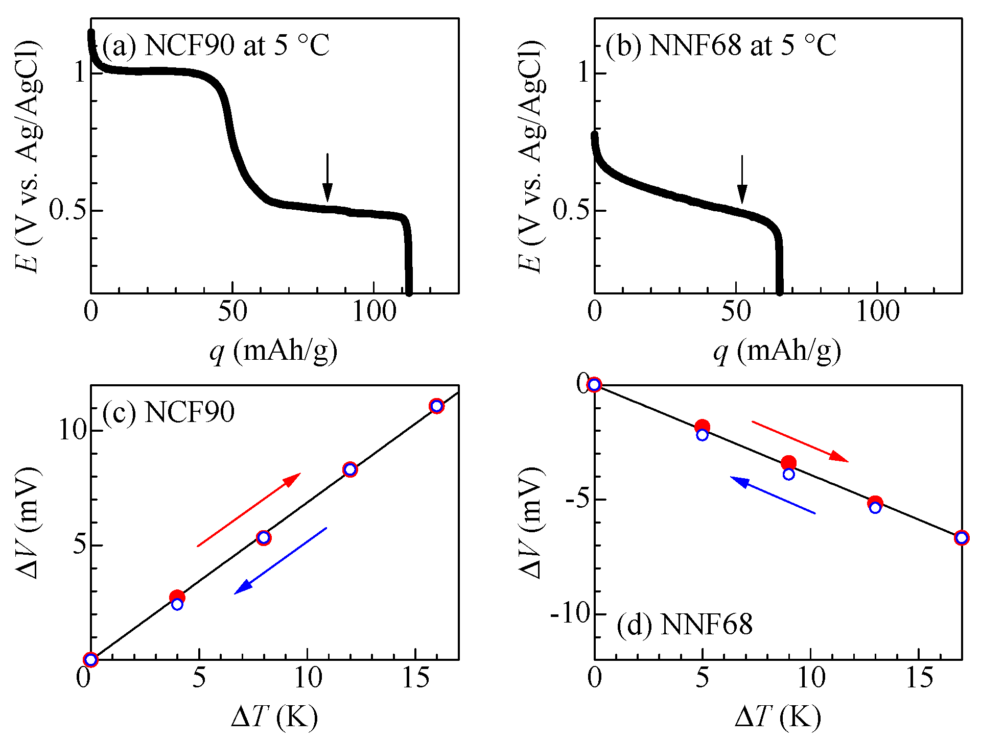
| Material | α (mV/K) | β (Ωg/h) | d (nm) | S(cm2) | m (μg) | E0 (mV) | |
| Electrolyte-free | NCF90 | 0.69 | 0.14 | 220 | 0.04 | 1.1 | 500 |
| NNF68 | −0.39 | 0.82 | 700 | 0.04 | 3.7 | 500 | |
| Conventional [8] | NCF90 | 1.53 | 3.3 | 300 | 1.0 | 36.4 | 500 |
| NNF68 | 0.23 | 2.0 | 280 | 1.0 | 37.1 | 500 |
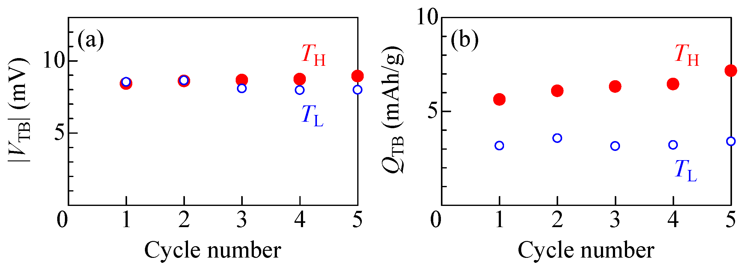
| Cathode | Anode | VTB (mV) | QTB (mAh/g) | ΔT (K) | VTB* (mV) | QTB* (mAh/g) | Ref. | |
| Electrolyte-free | NCF90 | NNF68 | 8.4 | 5.6 | 10 | 8.4 | 5.6 | This work |
| Conventional | NCF90 | NNF68 | 40 | 5 | 40 | 10 | 1.3 | [8] |
Disclaimer/Publisher’s Note: The statements, opinions and data contained in all publications are solely those of the individual author(s) and contributor(s) and not of MDPI and/or the editor(s). MDPI and/or the editor(s) disclaim responsibility for any injury to people or property resulting from any ideas, methods, instructions or products referred to in the content. |
© 2024 by the authors. Licensee MDPI, Basel, Switzerland. This article is an open access article distributed under the terms and conditions of the Creative Commons Attribution (CC BY) license (https://creativecommons.org/licenses/by/4.0/).
Share and Cite
Shibata, T.; Matsushima, H.; Nagai, I.; Ohnuki, H. An Electrolyte-Free Thermo-Rechargeable Battery Made of Prussian Blue Analog Thin Films. Processes 2024, 12, 175. https://doi.org/10.3390/pr12010175
Shibata T, Matsushima H, Nagai I, Ohnuki H. An Electrolyte-Free Thermo-Rechargeable Battery Made of Prussian Blue Analog Thin Films. Processes. 2024; 12(1):175. https://doi.org/10.3390/pr12010175
Chicago/Turabian StyleShibata, Takayuki, Hirotada Matsushima, Ichiro Nagai, and Hitoshi Ohnuki. 2024. "An Electrolyte-Free Thermo-Rechargeable Battery Made of Prussian Blue Analog Thin Films" Processes 12, no. 1: 175. https://doi.org/10.3390/pr12010175
APA StyleShibata, T., Matsushima, H., Nagai, I., & Ohnuki, H. (2024). An Electrolyte-Free Thermo-Rechargeable Battery Made of Prussian Blue Analog Thin Films. Processes, 12(1), 175. https://doi.org/10.3390/pr12010175