
Research on AGC Nonlinear Compensation Control for Electro-Hydraulic Servo Pump Control of a Lithium Battery Pole Strip Mill

Abstract
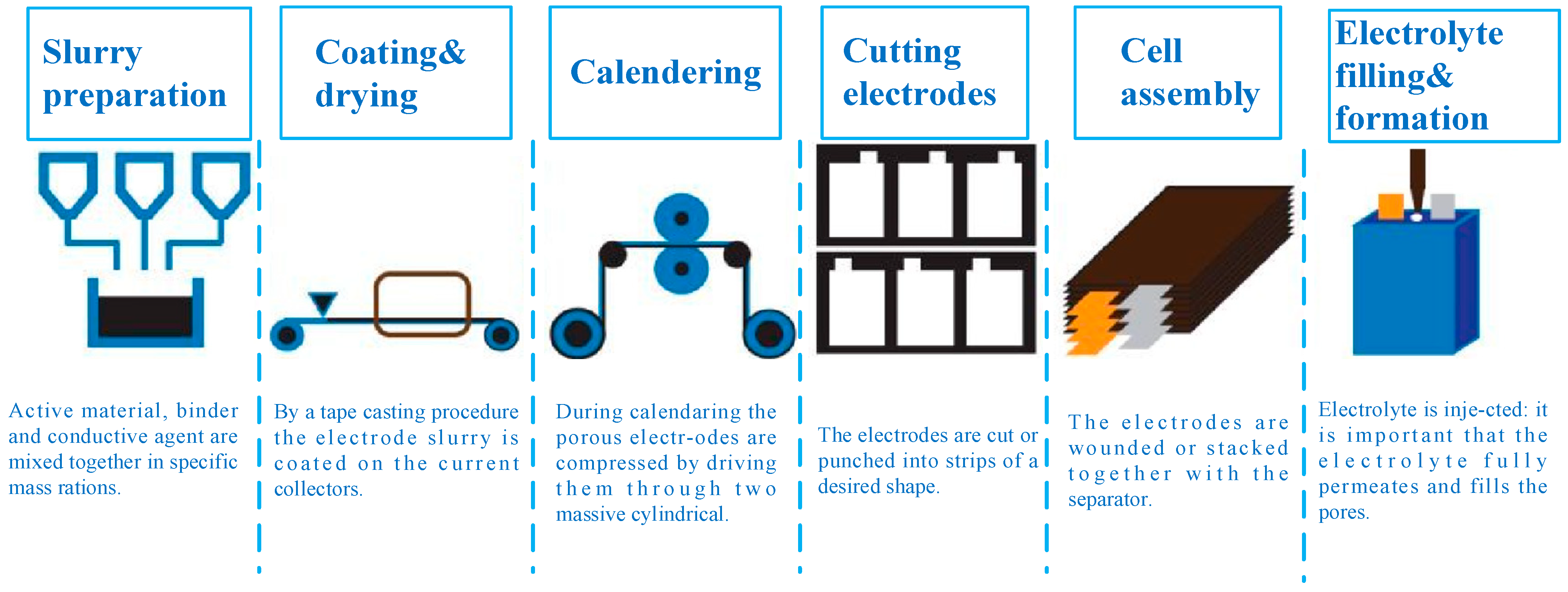
1. Introduction
2. Study on Nonlinear Stiffness Characteristics of Pole Mill
2.1. Research on Nonlinear Stiffness Characteristics of Polar Plate
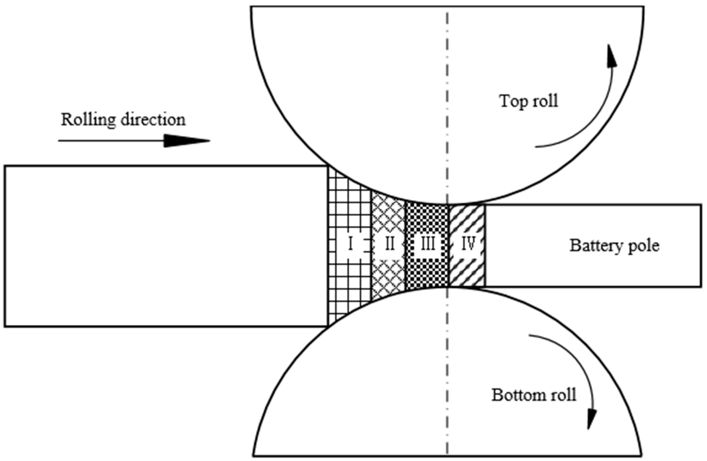
2.1.1. Theoretical Rolling Force Calculation of Pole Sheet
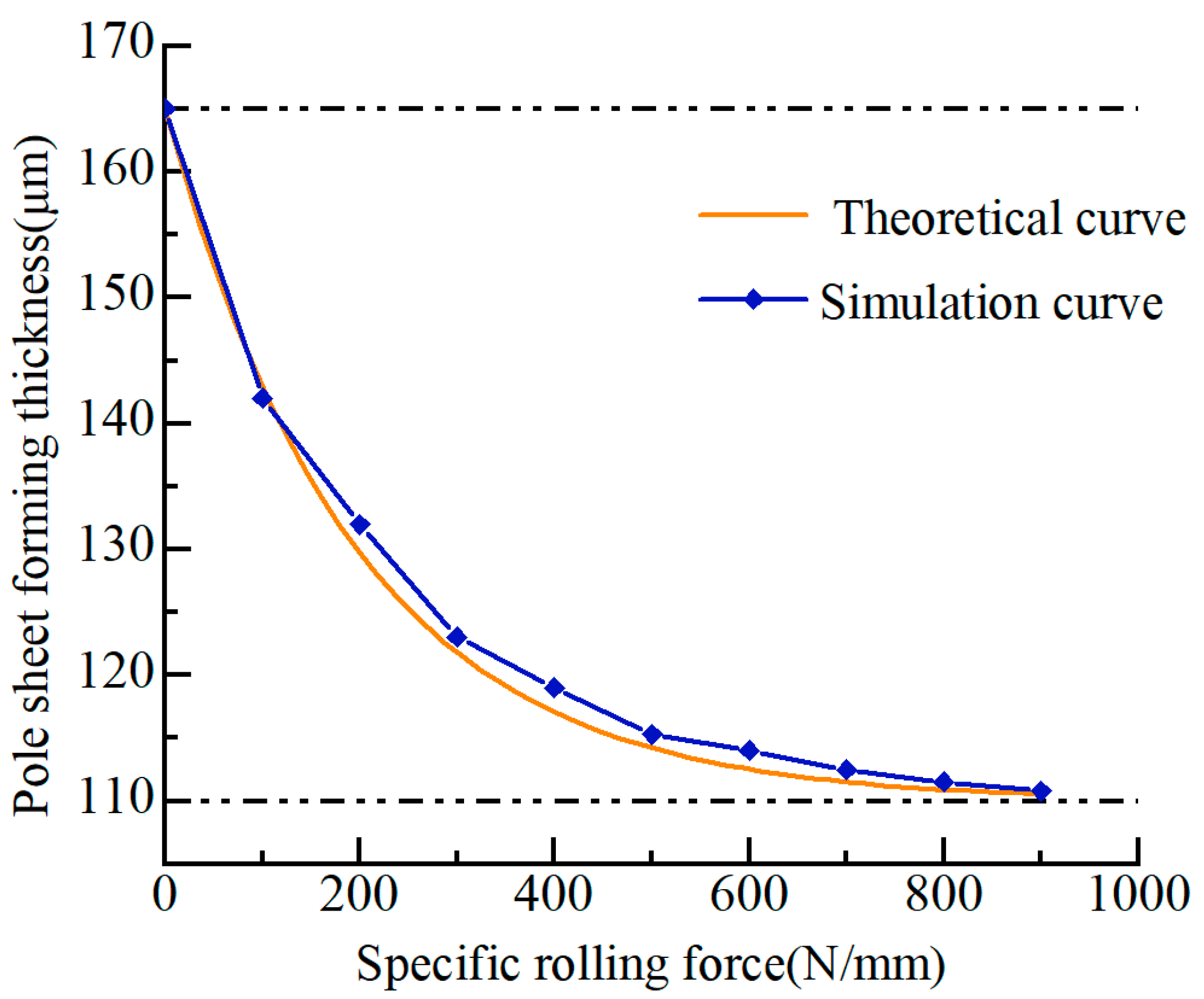
2.1.2. Theoretical Calculation of Rolling Thickness of Pole Sheet
2.1.3. Simulation of Nonlinear Stiffness Characteristics of Polar Plate
2.2. Research on Nonlinear Stiffness Characteristics of Hydraulic Cylinder
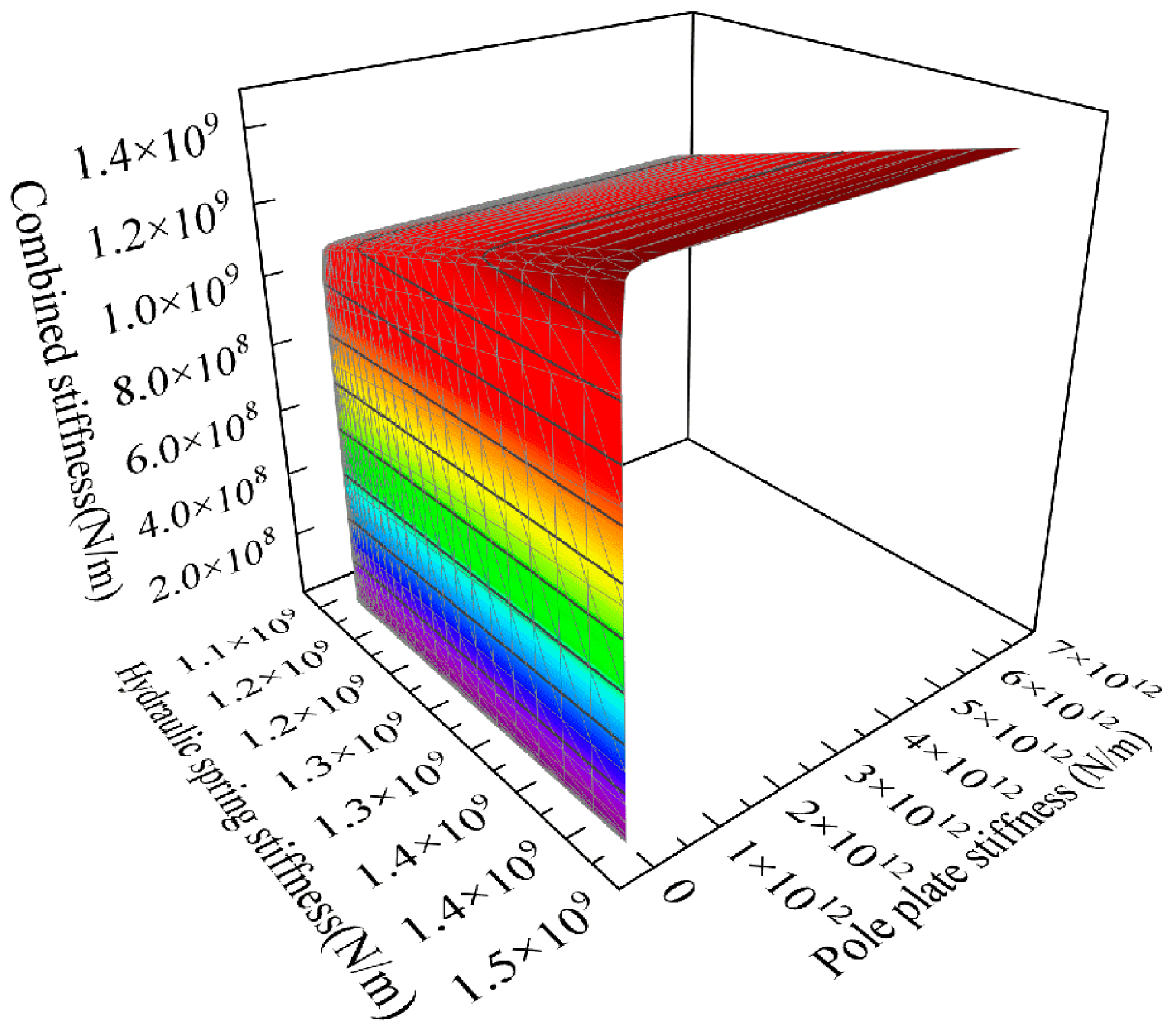
2.3. Nonlinear Stiffness Characteristic Analysis
3. Research on Nonlinear Transmission Characteristics of Pump-Controlled AGC
3.1. Study on Transmission Characteristics of Motor Pump Group
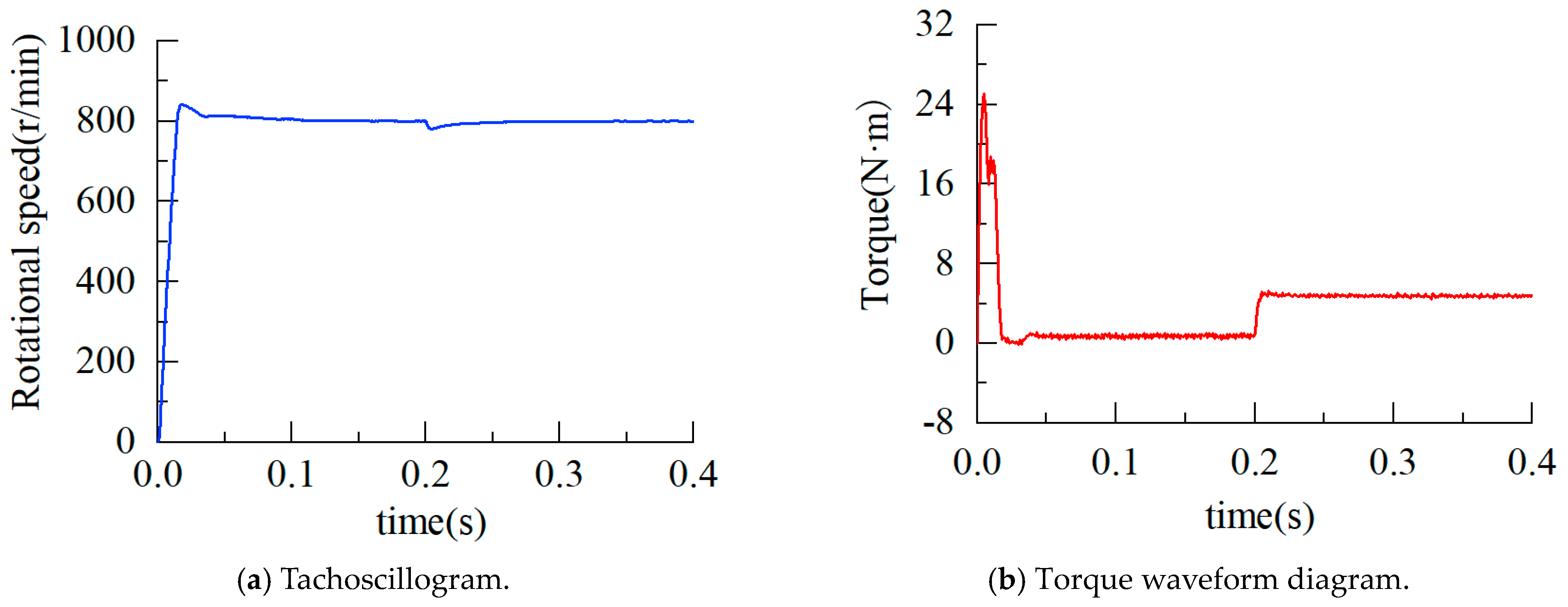
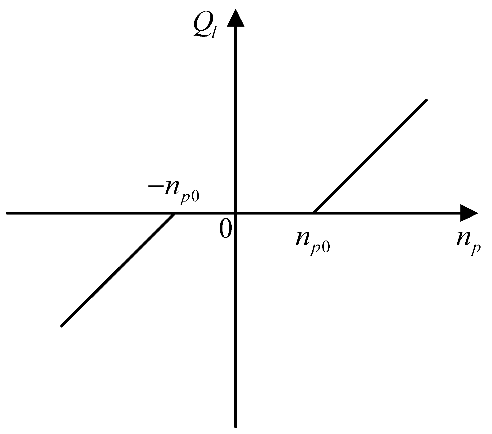
3.1.1. Research on Low-Speed Characteristics of Servo Motor
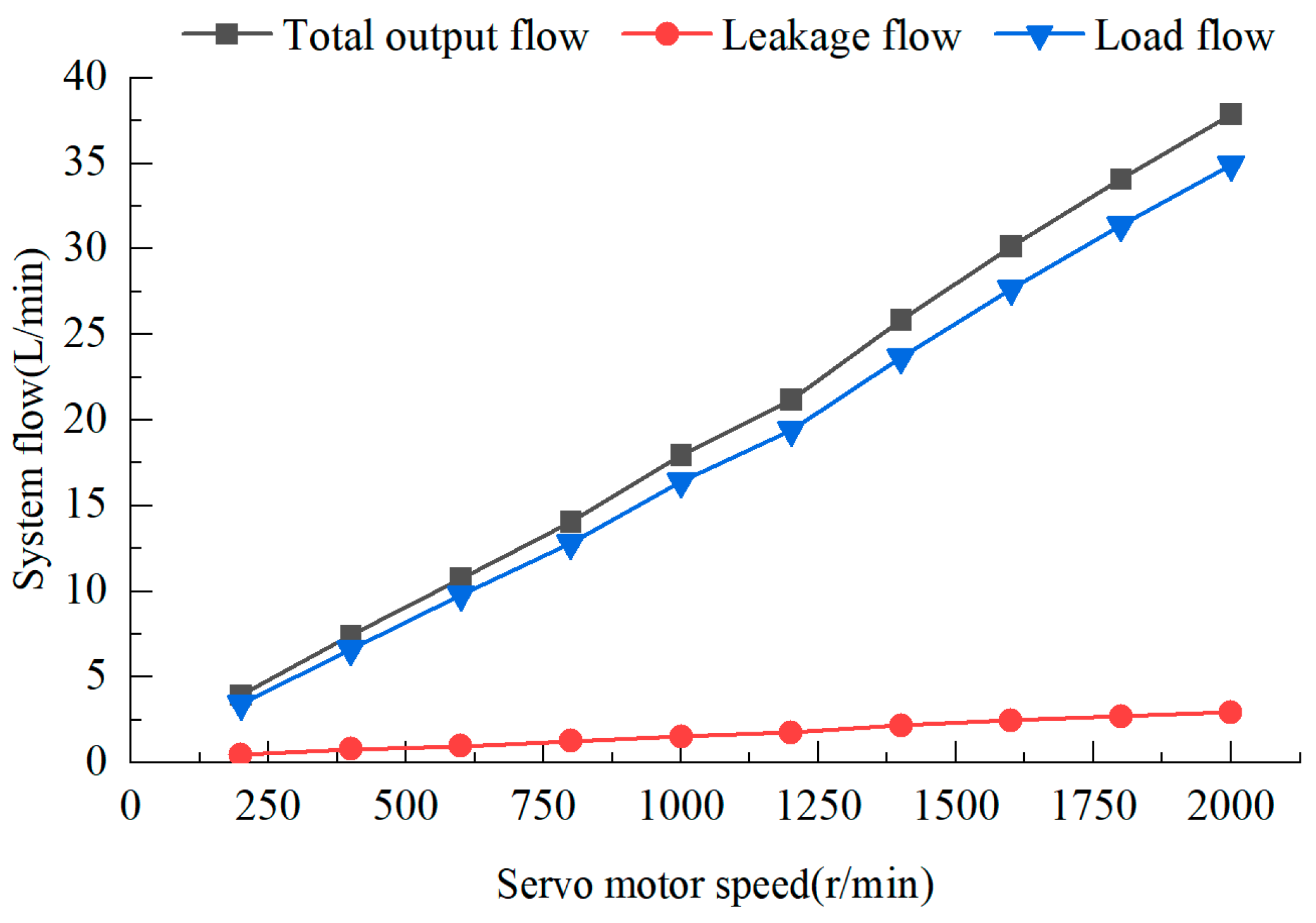
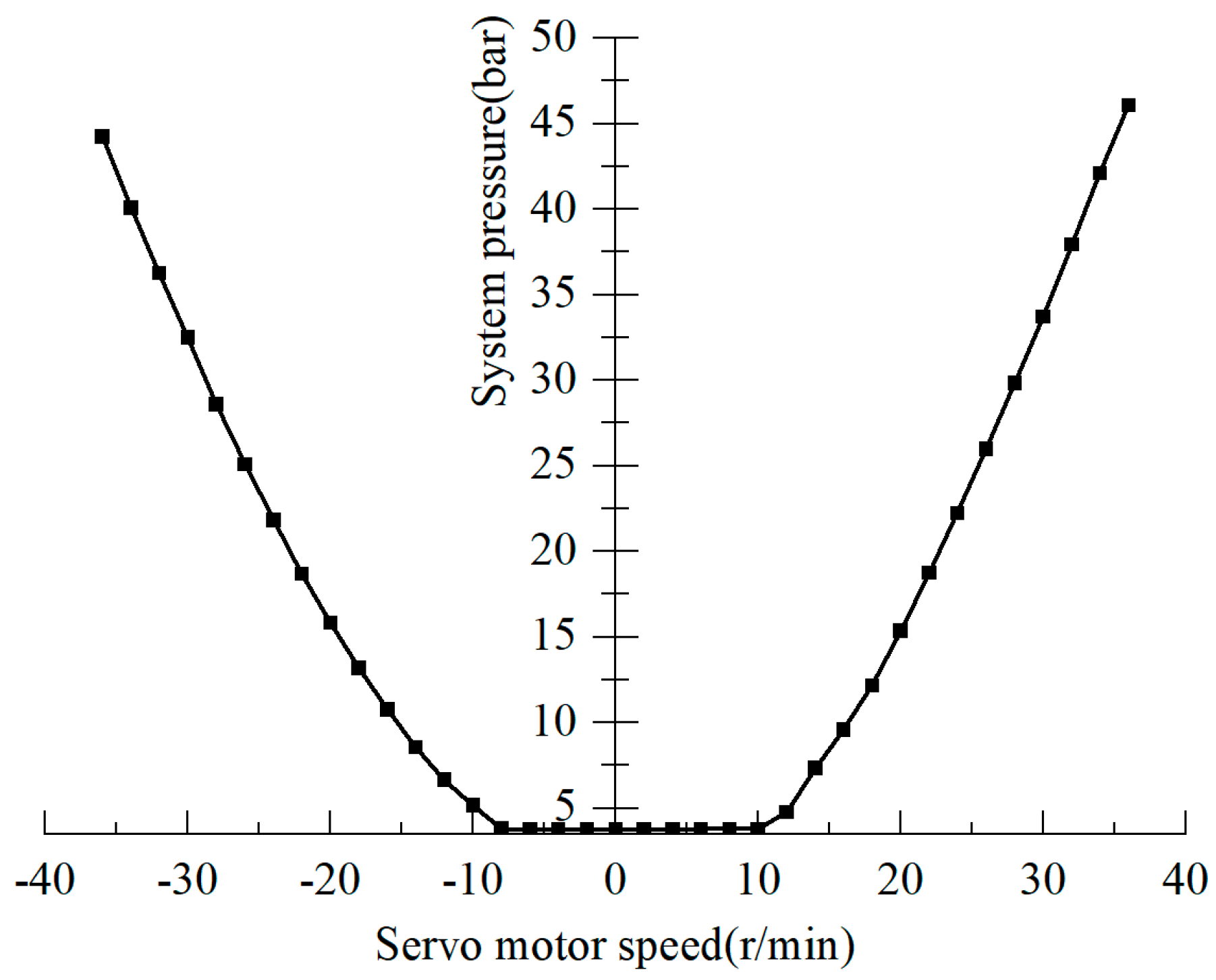
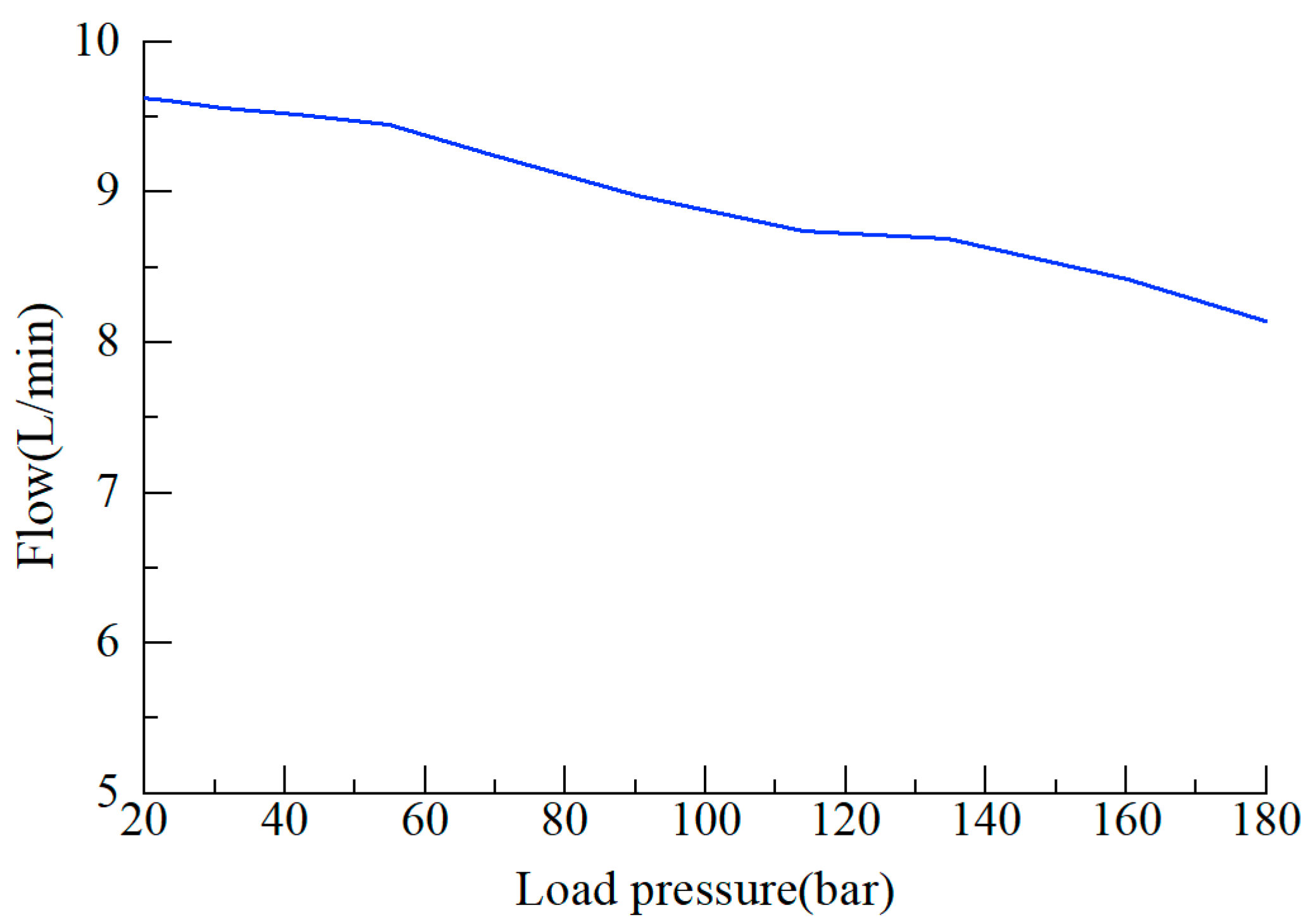
3.1.2. Research on Flow Output Characteristics of Hydraulic Pump
3.2. Research on Coupling Characteristics of Pump-Controlled Cylinder Drive System
4. Research on Pump-Controlled AGC High-Performance Thickness Control Strategy
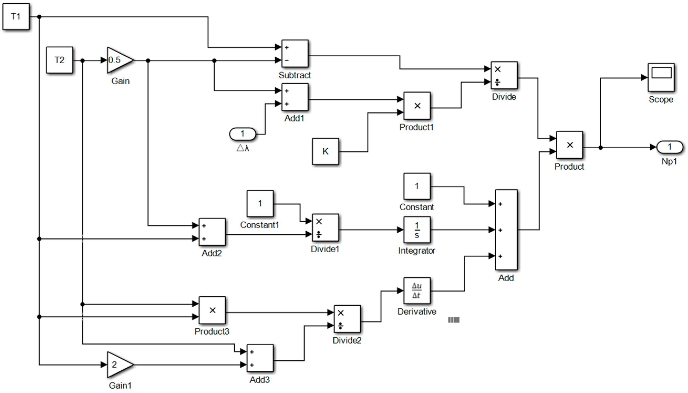
4.1. Research on Characteristic Compensation
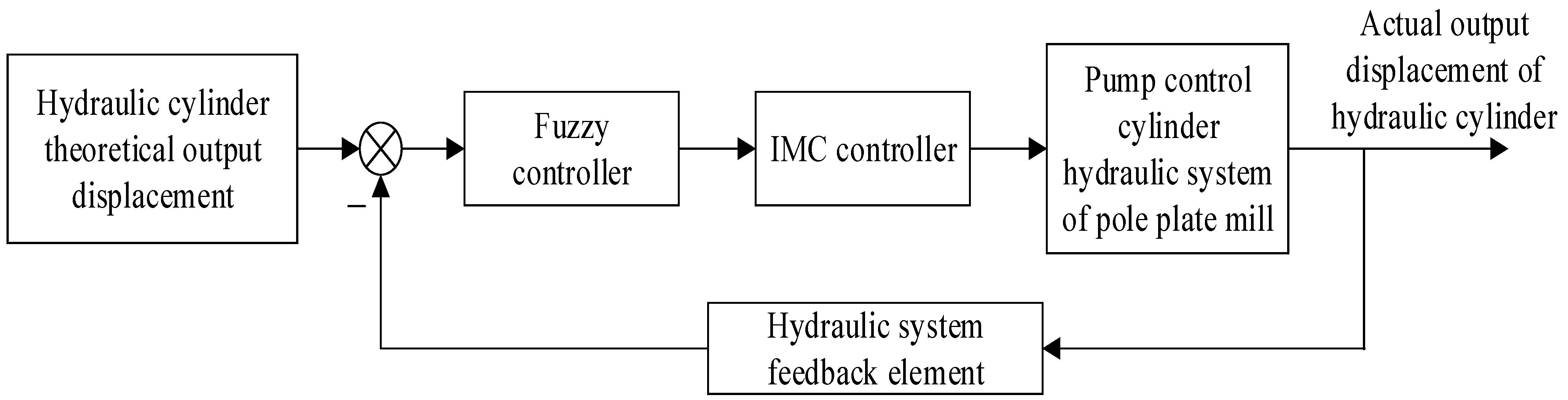
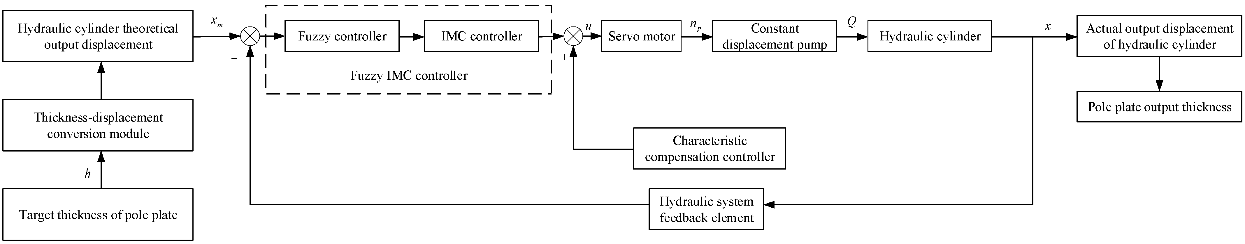
4.2. Research on Fuzzy Internal Model Structure Compensation Control
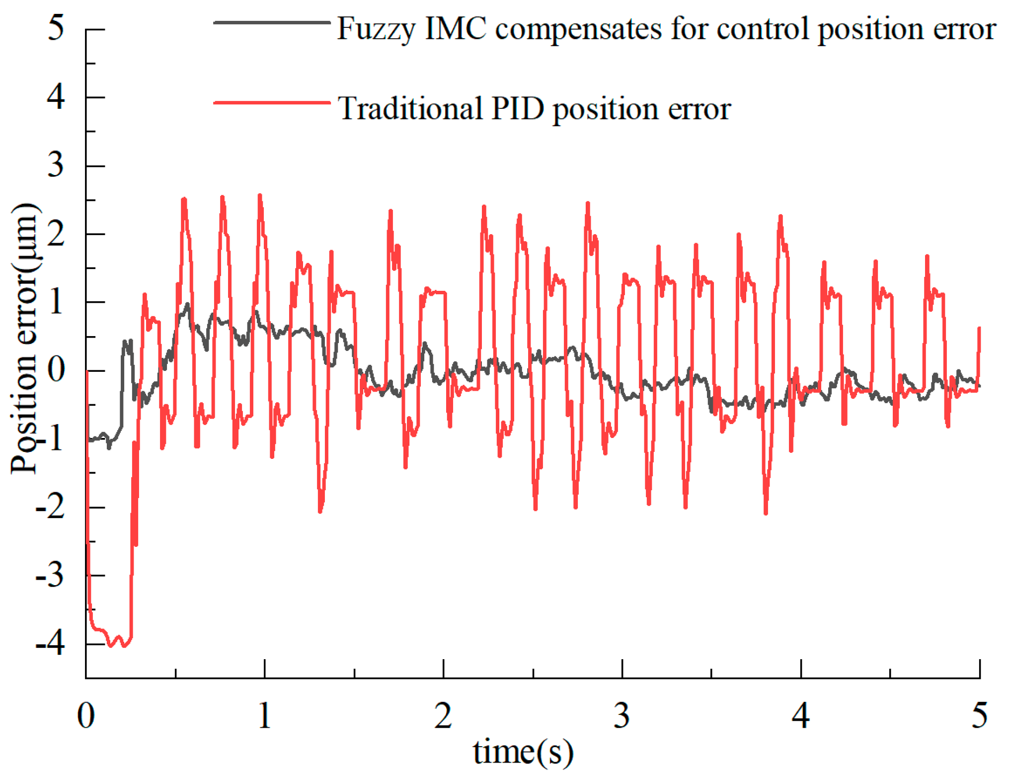
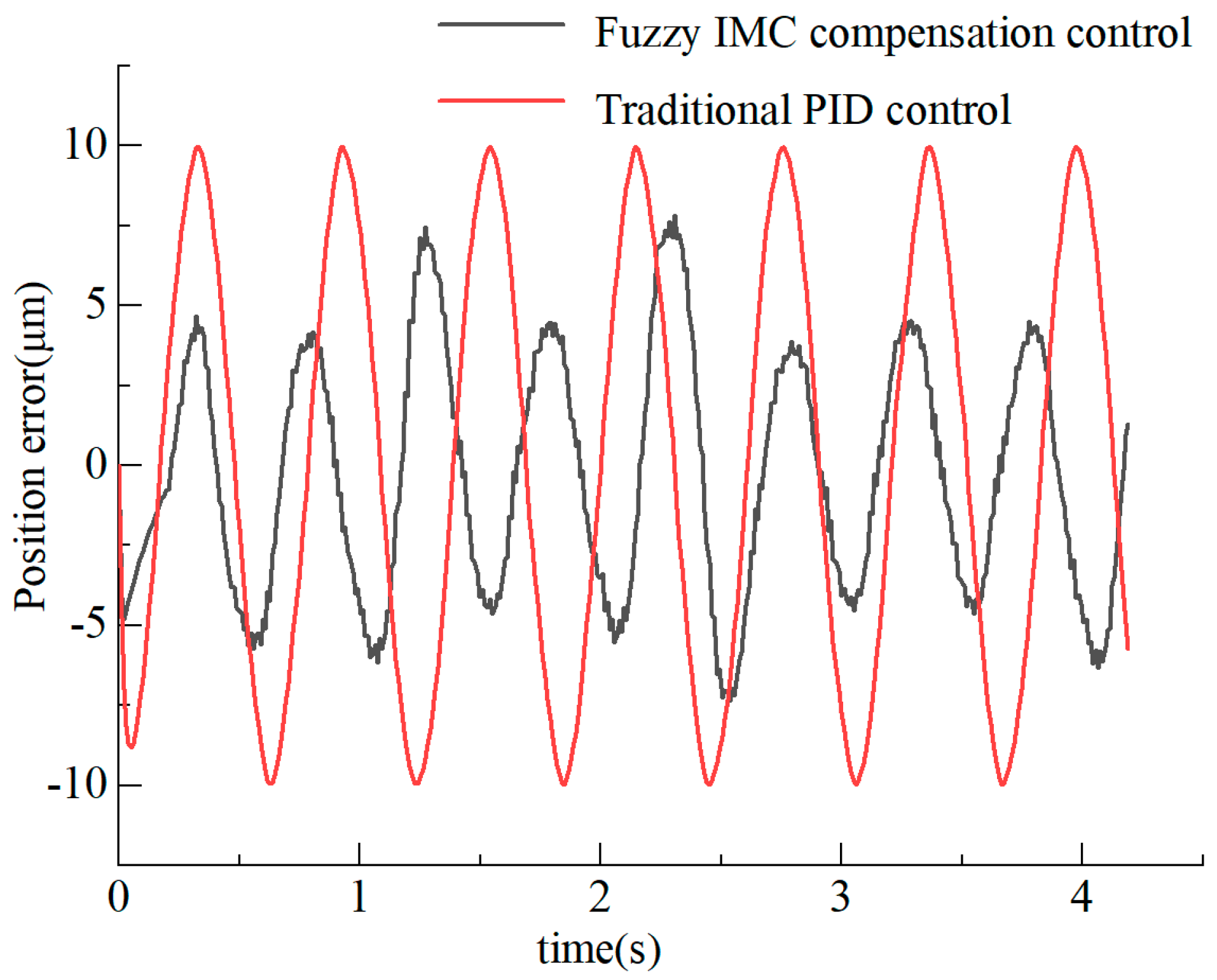
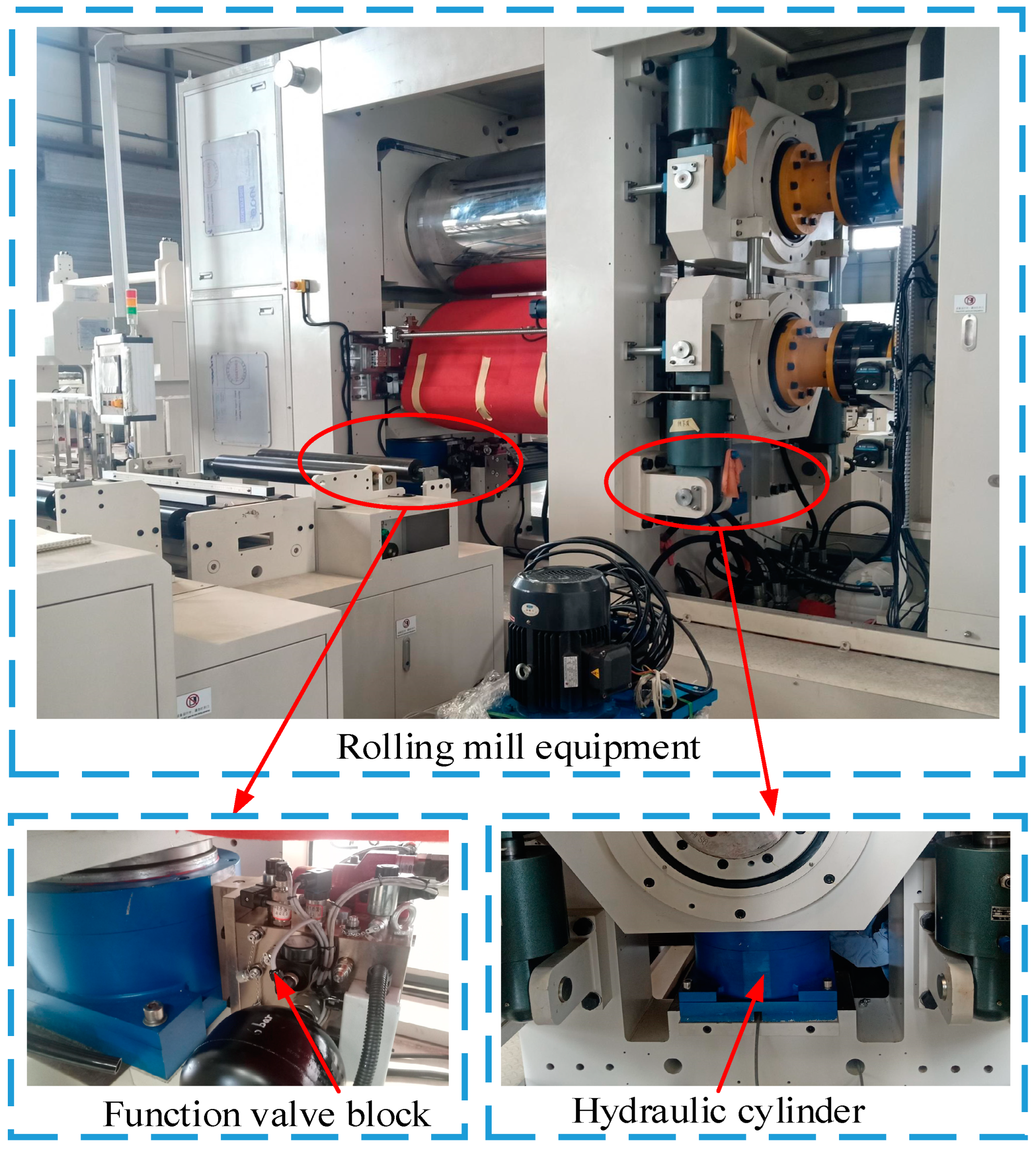
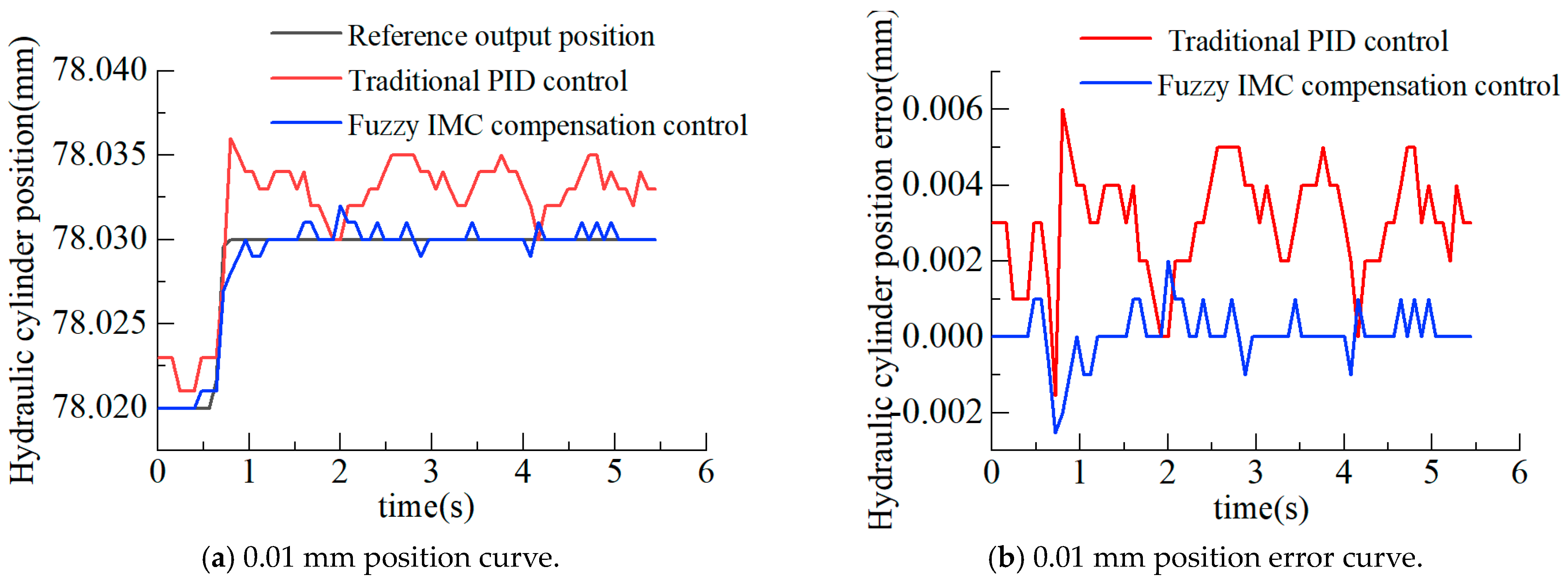
5. Engineering Experiment Application
6. Conclusions
Author Contributions
Funding
Institutional Review Board Statement
Informed Consent Statement
Data Availability Statement
Conflicts of Interest
References
- Xiao, Y.; Deng, S.; Liu, W.; Zhou, W.; Wan, F. Optimized Design of Battery Pole Control System Based on Dual-chip Architecture. PLoS ONE 2022, 17, e0264285. [Google Scholar] [CrossRef] [PubMed]
- Meyer, C.; Weyhe, M.; Haselrieder, W.; Kwade, A. Heated Calendering of Cathodes for Lithium-Ion Batteries with Varied Carbon Black and Binder Contents. Energy Technol. 2020, 8, 1900175. [Google Scholar] [CrossRef]
- Jiang, W.; Jia, P.; Yan, G.; Chen, G.; Ai, C.; Zhang, T.; Shen, W. Dynamic Response Analysis of Control Loops in an Electro-Hydraulic Servo Pump Control System. Processes 2022, 10, 1647. [Google Scholar] [CrossRef]
- Yan, G.; Jin, Z.; Zhang, T.; Zhang, C.; Ai, C.; Chen, G. Exploring the Essence of Servo Pump Control. Processes 2022, 10, 786. [Google Scholar] [CrossRef]
- Meyer, C.; Kosfeld, M.; Haselrieder, W.; Kwade, A. Process Modeling of the Electrode Calendering of Lithium-ion Batteries Regarding Variation of Cathode Active Materials and Mass Loadings. J. Energy Storage 2018, 18, 371–379. [Google Scholar] [CrossRef]
- Xu, Y.X.; Niu, L.C.; Yang, H.; Xiao, Y.C.; Xiao, Y.J. Optimization of Lithium Battery Pole Piece Thickness Control System Based on GA-BP Neural Network. J. Nanoelectron. Optoelectron. 2019, 14, 978–986. [Google Scholar] [CrossRef]
- Giménez, C.S.; Finke, B.; Nowak, C.; Schilde, C.; Kwade, A. Structural and Mechanical Characterization of Lithium-ion Battery Electrodes Via DEM Simulations. Adcanced Powder Technol. 2018, 29, 2312–2321. [Google Scholar] [CrossRef]
- Giménez, C.S.; Finke, B.; Schilde, C.; Froböse, L.; Kwade, A. Numerical Simulation of the Behavior of Lithium-ion Battery Electrodes During the Calendaring Process Via the Discrete Element Method. Powder Technol. 2019, 349, 1–11. [Google Scholar] [CrossRef]
- Sangrós Giménez, C.; Schilde, C.; Froböse, L.; Ivanov, S.; Kwade, A. Mechanical Electrical and Ionic Behavior of Lithium on Battery Electrodes Via DEM Simulations. Energy Technol. 2020, 8, 1900180. [Google Scholar] [CrossRef]
- Park, K.; Myeong, S.; Shin, D.; Cho, C.W.; Kim, S.C.; Song, T. Improved Swelling Behavior of Li Ion Batteries by Microstructural Engineering of Anode. J. Ind. Eng. Chem. 2019, 71, 270–276. [Google Scholar] [CrossRef]
- Duffner, F.; Kronemeyer, N.; Tübke, J.; Leker, J.; Winter, M.; Schmuch, R. Post-lithium-ion Battery Cell Production and its Compatibility with Lithium-ion Cell Production Infrastructure. Nat. Energy 2021, 6, 123–134. [Google Scholar] [CrossRef]
- Maghareh, A.; Silva, C.E.; Dyke, S.J. Servo-Hydraulic Actuator in Controllable Canonical Form: Identification and Experimental Validation. Mech. Syst. Signal Process. 2018, 100, 398–414. [Google Scholar] [CrossRef]
- Park, H.G.; Jeong, K.H.; Park, M.K.; Lee, S.H.; Ahn, K.K. Electro Hydrostatic Actuator System Based on Active Stabilizer System for Vehicular Suspension Systems. Int. J. Precis. Eng. Manuf. 2018, 19, 993–1001. [Google Scholar] [CrossRef]
- Tri, N.M.; Binh, P.C.; Ahn, K.K. Power Take-off System Based on Continuously Variable Transmission Configuration for Wave Energy Converter. Int. J. Precis. Eng. Manuf.-Green Technol. 2018, 5, 103–110. [Google Scholar] [CrossRef]
- Zhang, J.; Li, Y.; Xu, B.; Chen, X.; Pan, M. Churning Losses Analysis on the Thermal-hydraulic Model of a High-speed Electro-hydrostatic Actuator Pump. Int. J. Heat Mass Transf. 2018, 127, 1023–1030. [Google Scholar] [CrossRef]
- Li, Y.H.; Ji, Z.L.; Yang, L.M.; Zhang, P.; Xu, B.; Zhang, J.H. Thermal-Fluid-Structure Coupling Analysis for Valve Plate Friction Pair of Axial Piston Pump in Electro-hydrostatic Actuator (EHA) of Aircraft. Appl. Math. Model. 2017, 47, 839–858. [Google Scholar] [CrossRef]
- Zhang, J.; Chen, Y.; Xu, B.; Pan, M.; Chao, Q. Effects of Splined Shaft Bending Rigidity on Cylinder Tilt Behaviour for High-Speed Electrohydrostatic Actuator Pumps. Chin. J. Aeronaut. 2019, 32, 499–512. [Google Scholar] [CrossRef]
- Lee, W.; Kim, M.J.; Chung, W.K. Asymptotically Stable Disturbance Observer-Based Compliance Control of Electro-hydrostatic Actuators. IEEE/ASME Trans. Mechatron. 2019, 25, 195–206. [Google Scholar] [CrossRef]
- Antartis, D.; Dillon, S.; Chasiotis, I. Effect of Porosity on Electrochemical and Mechanical Properties of Composite Li-ion Anodes. J. Compos. Mater. 2015, 49, 1849–1862. [Google Scholar] [CrossRef]
- Guan, Y.M.; Jiang, Z.; Zhao, F.H.; Qiu, Z.Z. Research on the Unevenness of Lithium Battery Plate and Structure Optimization Analysis of Roller Press. Mech. Sci. Technol. Aerosp. Eng. 2018, 37, 287–292. [Google Scholar]
- Zad, H.S.; Ulasyar, A.; Zohaib, A. Robust Model Predictive Position Control of Direct Drive Electro-Hydraulic Servo System. In Proceedings of the 2016 International Conference on Intelligent Systems Engineering (ICISE), Islamabad, Pakistan, 15–17 January 2016; pp. 100–104. [Google Scholar]
- Soon, C.C.; Ghazali, R.; Jaafar, H.I.; Hussien, S.Y.S. Sliding Mode Controller Design with Optimized PID Sliding Surface Using Particle Swarm Algorithm. Procedia Comput. Sci. 2017, 105, 235–239. [Google Scholar] [CrossRef]
- Ren, G.; Esfandiari, M.; Song, J.; Sepehri, N. Position Control of an Electro-hydrostatic Actuator with Tolerance to Internal Leakage. IEEE Trans. Control. Syst. Technol. 2016, 24, 2224–2232. [Google Scholar] [CrossRef]
- Cao, F. PID Controller Optimized by Genetic Algorithm for Direct-Drive Servo System. Neural Comput. Appl. 2020, 32, 23–30. [Google Scholar] [CrossRef]
- Hong, W.; Wang, S.; Tomovic, M.M.; Liu, H.; Shi, J.; Wang, X. A Novel Indicator for Mechanical Failure and Life Prediction Based on Debris Monitoring. IEEE Trans. Reliab. 2016, 66, 161–169. [Google Scholar] [CrossRef]
- Lu, C.; Wang, S.; Makis, V. Fault Severity Recognition of Aviation Piston Pump Based on Feature Extraction of EEMD Paving and Optimized Support Vector Regression Model. Aerosp. Sci. Technol. 2017, 67, 105–117. [Google Scholar] [CrossRef]
- Li, X.; Jiao, Z.; Yan, L.; Cao, Y. Modeling and Experimental Study on a Novel Linear Electromagnetic Collaborative Rectification Pump. Sens. Actuators A Phys. 2020, 309, 111883. [Google Scholar] [CrossRef]
- Fallahi, M.; Zareinejad, M.; Baghestan, K.; Tivay, A.; Rezaei, S.M.; Abdullah, A. Precise Position Control of an Electro-Hydraulic Servo System Via Robust Linear Approximation. ISA Trans. 2018, 80, 503–512. [Google Scholar] [CrossRef] [PubMed]
- Wang, Z. Research on Rolling Mechanism and Simulation of Battery Pole Sheet Roll; Hebei University of Technology: Tianjin, China, 2018; pp. 12–13. [Google Scholar]
- Zhou, J.; Wen, C.; Zhang, Y. Adaptive Output Control of Nonlinear Systems with Uncertain Dead-Zone Nonlinearity. IEEE Trans. Autom. Control. 2006, 51, 504–511. [Google Scholar] [CrossRef]
- Song, J.Q.; Liu, X.J.; Tian, J.H. Multi-model internal model control method for steam generator water level control in nuclear power plant. J. Taiyuan Univ. Sci. Technol. 2014, 35, 166–170. [Google Scholar]
- Chen, Y.T. Paper Quantitative Control based on fuzzy setpoint weighted IMC-PID Algorithm. Packag. Eng. 2018, 39, 157–162. [Google Scholar]


| Physical Name | Parameter | Unit |
|---|---|---|
| Roll diameter | 600 | mm |
| Roll body length | 500 | mm |
| Roll gap size | 110 | μm |
| Initial thickness of pole plate | 165 | μm |
| Polar sheet material | Graphite | - |
| Compressive impedance parameters | 195 | - |
| Name | Type | Manufacturers |
|---|---|---|
| Oil filter | DF ON 30 Q E 20 D 1.0 | HYDAC |
| Two position three-way directional valve | DWDA-MAN-224 | SUN |
| Check valve | CXED-XAN | SUN |
| Safety relief valve | RDBA-LCV | SUN |
| Two position two-way switch valve | DTDA-MCN-224 | SUN |
Disclaimer/Publisher’s Note: The statements, opinions and data contained in all publications are solely those of the individual author(s) and contributor(s) and not of MDPI and/or the editor(s). MDPI and/or the editor(s) disclaim responsibility for any injury to people or property resulting from any ideas, methods, instructions or products referred to in the content. |
© 2024 by the authors. Licensee MDPI, Basel, Switzerland. This article is an open access article distributed under the terms and conditions of the Creative Commons Attribution (CC BY) license (https://creativecommons.org/licenses/by/4.0/).
Share and Cite
Wang, K.; Chen, G.; Zhang, C.; Liu, K.; Wang, F. Research on AGC Nonlinear Compensation Control for Electro-Hydraulic Servo Pump Control of a Lithium Battery Pole Strip Mill. Processes 2024, 12, 158. https://doi.org/10.3390/pr12010158
Wang K, Chen G, Zhang C, Liu K, Wang F. Research on AGC Nonlinear Compensation Control for Electro-Hydraulic Servo Pump Control of a Lithium Battery Pole Strip Mill. Processes. 2024; 12(1):158. https://doi.org/10.3390/pr12010158
Chicago/Turabian StyleWang, Kai, Gexin Chen, Cheng Zhang, Keyi Liu, and Fei Wang. 2024. "Research on AGC Nonlinear Compensation Control for Electro-Hydraulic Servo Pump Control of a Lithium Battery Pole Strip Mill" Processes 12, no. 1: 158. https://doi.org/10.3390/pr12010158
APA StyleWang, K., Chen, G., Zhang, C., Liu, K., & Wang, F. (2024). Research on AGC Nonlinear Compensation Control for Electro-Hydraulic Servo Pump Control of a Lithium Battery Pole Strip Mill. Processes, 12(1), 158. https://doi.org/10.3390/pr12010158