
Combustion Process of the Compound Supply CNG Engine

Abstract
:1. Introduction
2. Structural Design of a Natural Gas Engine with Compound Gas Supply
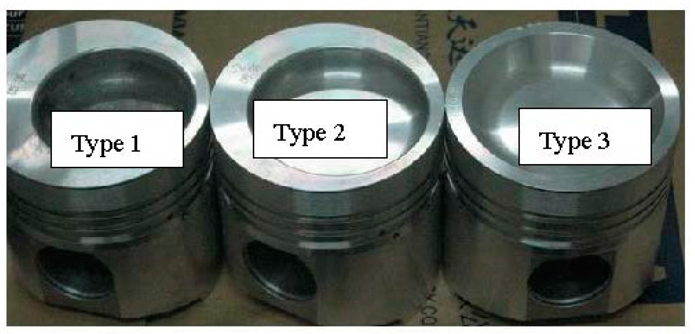
2.1. Piston Design
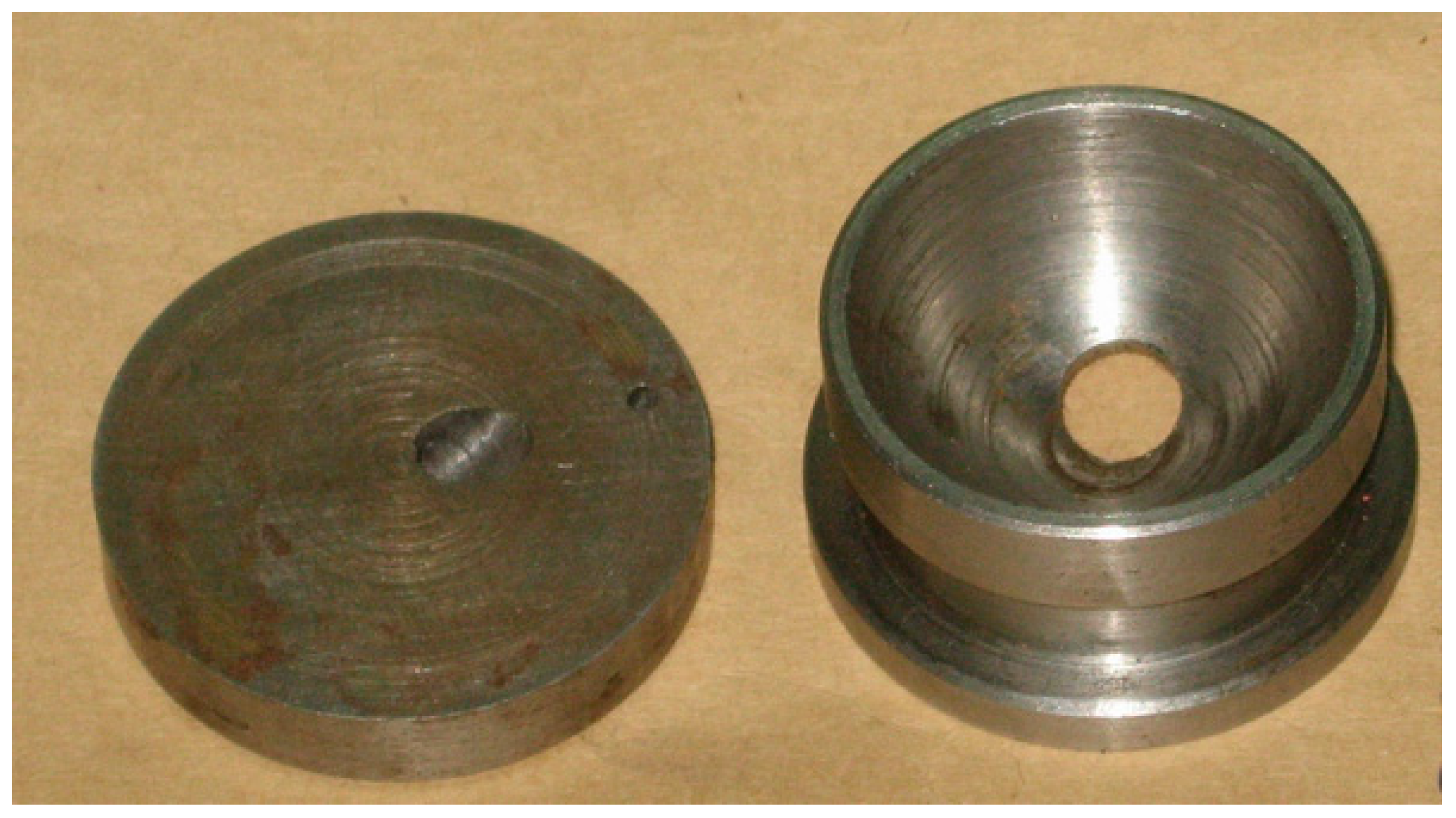
2.2. Inserts Design
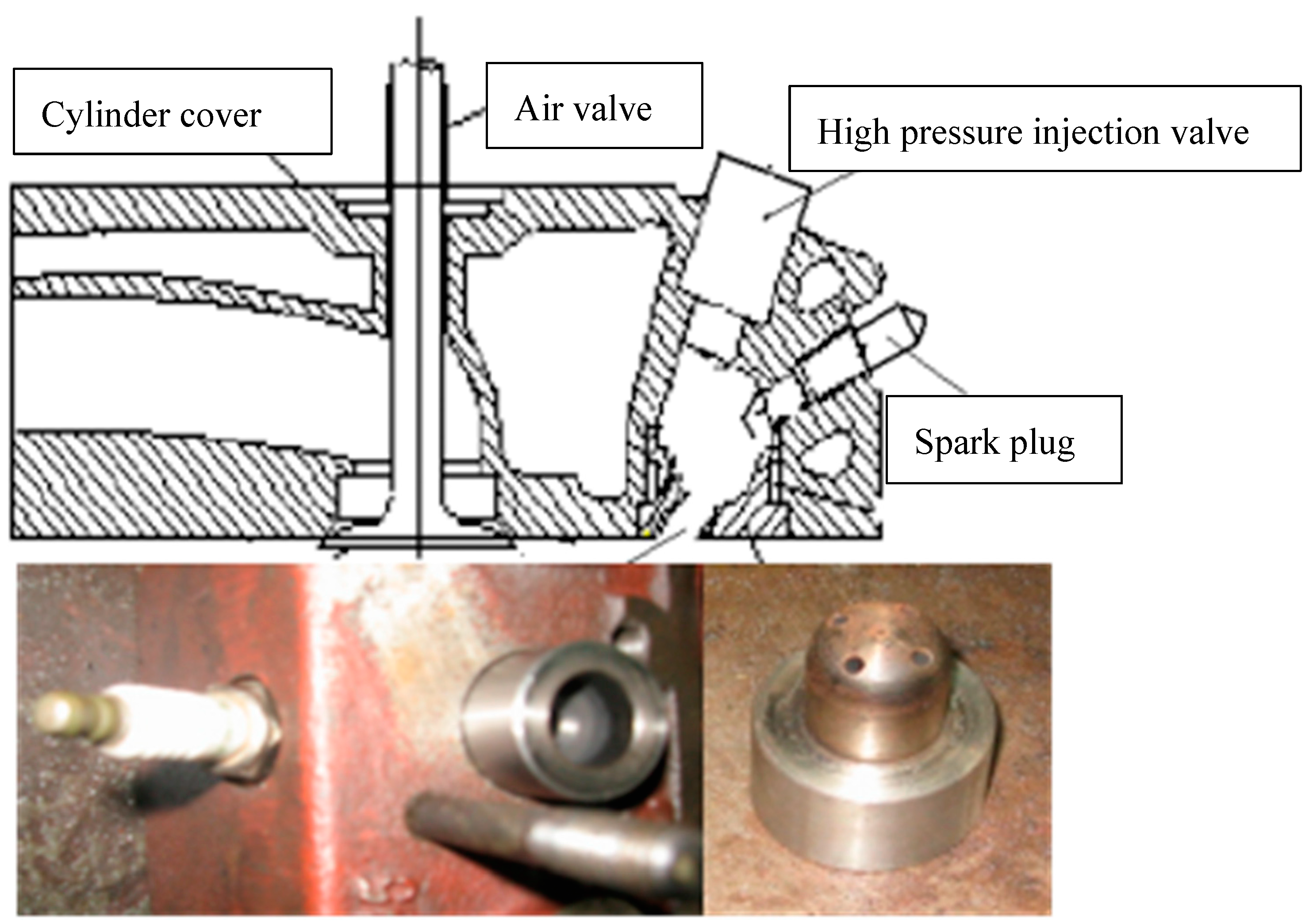
2.3. Installation of Injection Valve and Spark Plug
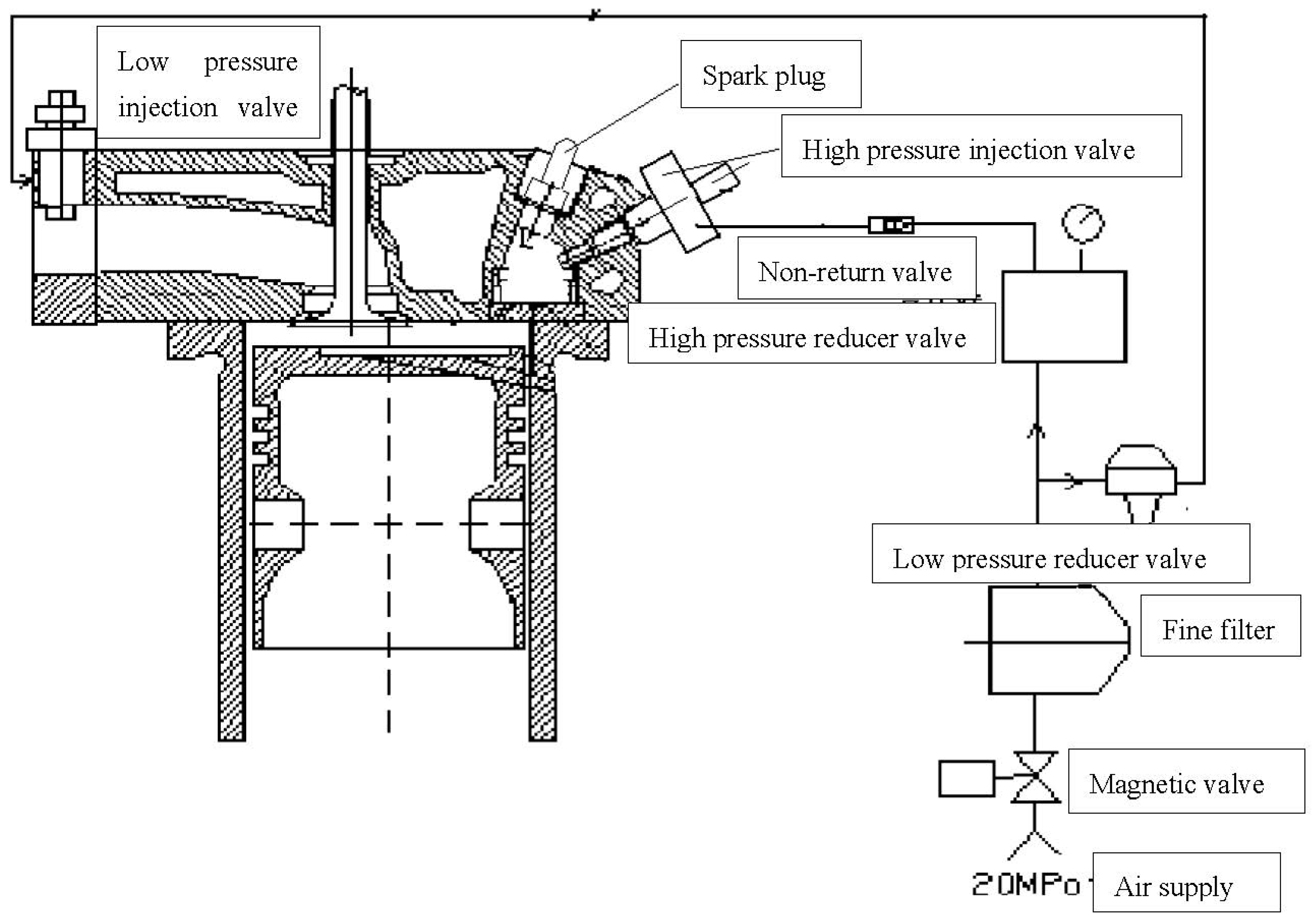
2.4. Natural Gas Supply System Composition
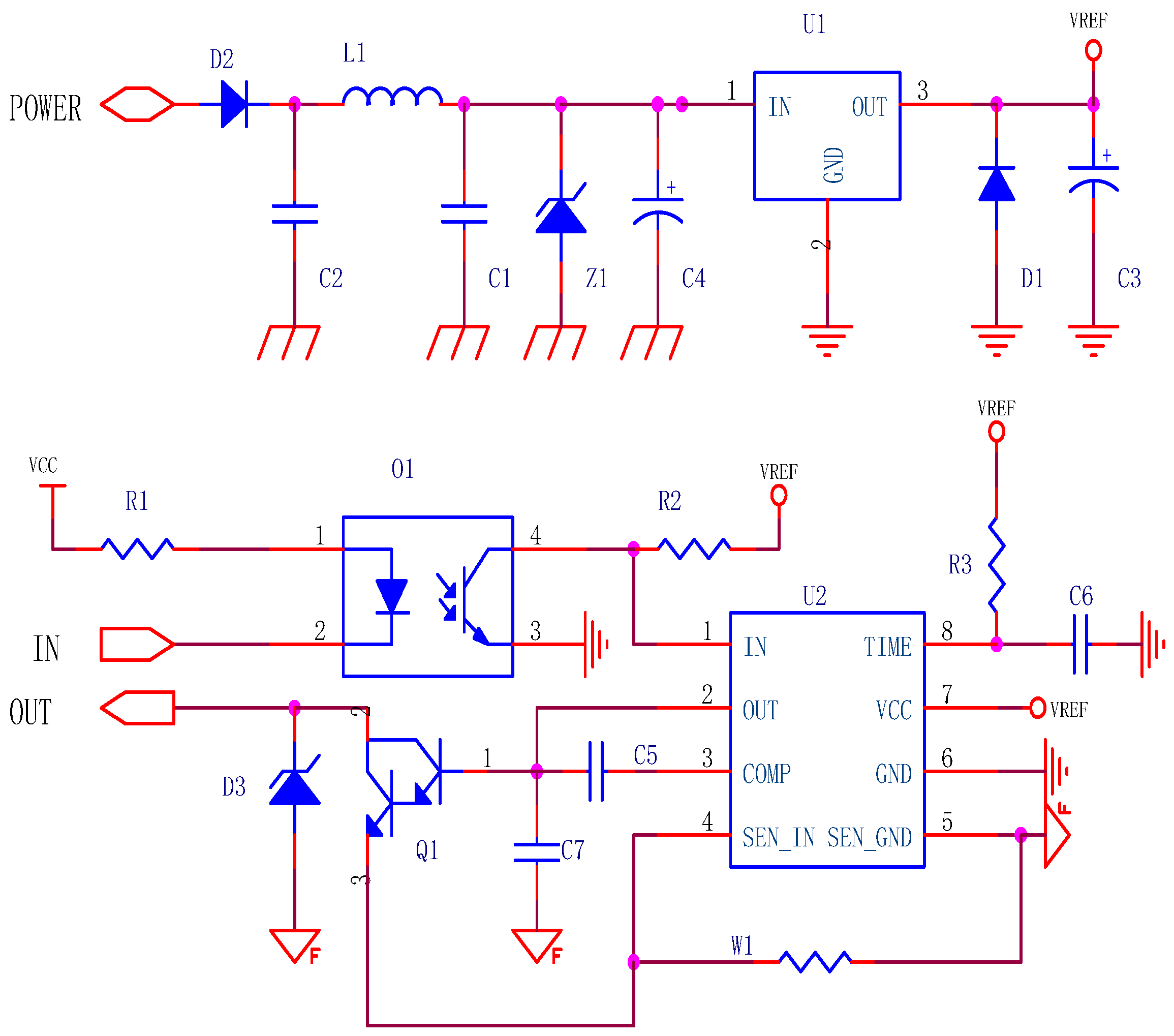
2.5. Injection Valve Drive Module Design
- (1)
- Voltage and current range
- (2)
- Input signal
- (3)
- Table 1 describes the drive ports.
3. Design of Electric Control System of Natural Gas Engine with Compound Gas Supply
3.1. Design of Electronic Control System for Gas Supply
3.1.1. Electronic Control Injection System Hardware
- 16 single-end input, 12 bits A/D;
- Speed: 400 KHZ, input voltage: 5/10/±5/±10 V;
- Working mode: timer trigger, external clock trigger, external hardware trigger;
- 4 K word FIFO, support continuous acquisition, automatic channel scanning;
- Two-channel 12-bit D/A, output 10/±10 volts;
- Switching capacity: 8 in/8 out (output pull-down current: 100 MA).
- 32-bit PCI bus, plug and play;
- Board with four 82C54 timer/counter chips;
- 10 independent 16-bit decrement counters;
- Cascade counter based on 8 MHz system clock.
- Provides anti-bounce filtering for external clock input signals and external interrupt signals;
- Anti-bounce clock frequency can be programmed;
- Universal 8-way TTL digital input and 8-way TTL digital output;
- Dual interrupt system;
- Supports 5 V and 12 V power supply protection;
- Compact half-length card structure;
- 100-pin SCSI-II connector.
3.1.2. Parameter Acquisition
Sampling Frequency
FIFO
3.2. Electronic Ignition System Design
3.2.1. Signal Acquisition System
3.2.2. System Control Unit
3.2.3. Display Unit
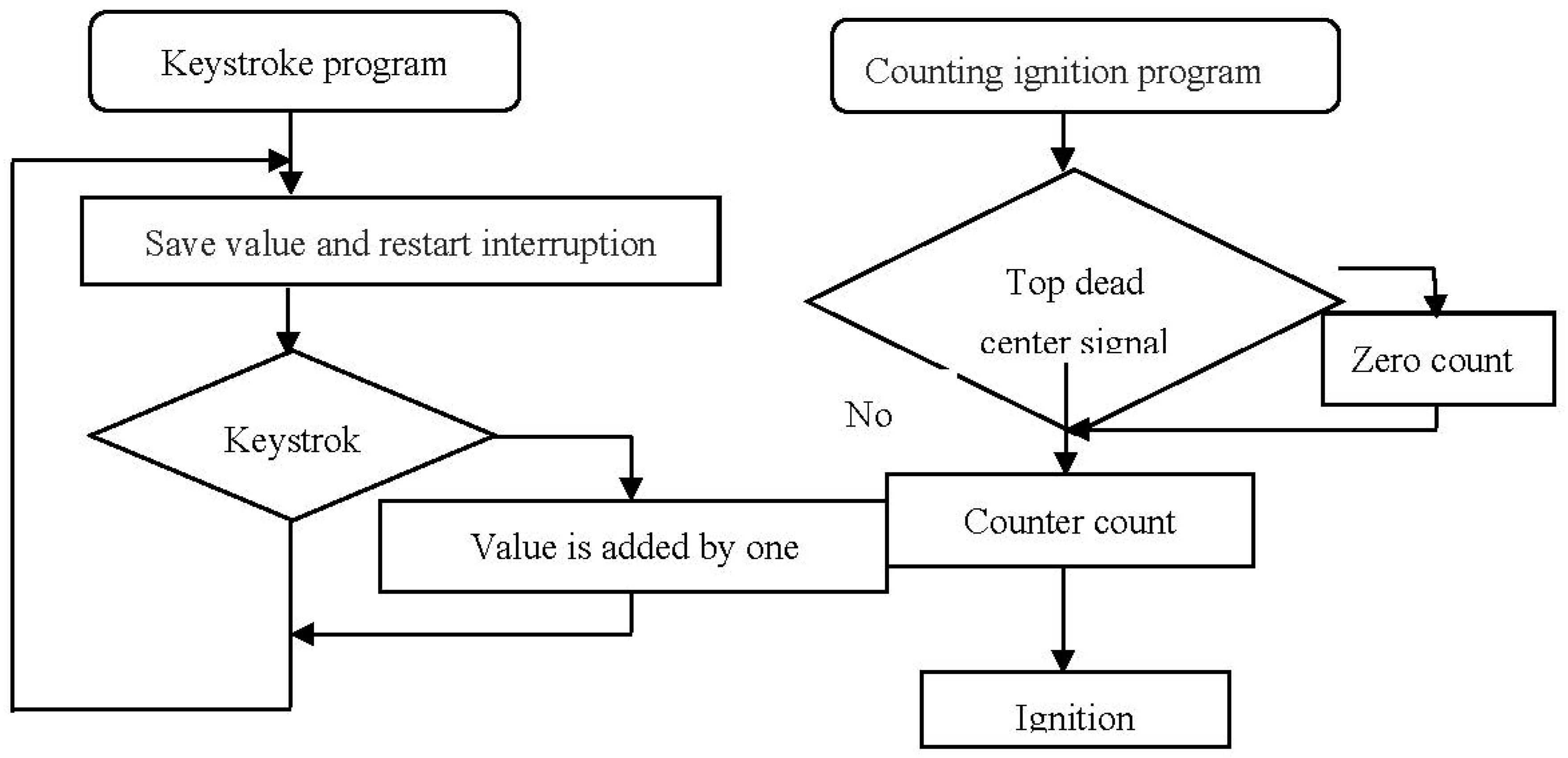
3.2.4. Ignition Control Unit
- (1)
- Ignition coil
- (2)
- Ignition module
- (3)
- Spark plug
4. Test Methods and Analysis
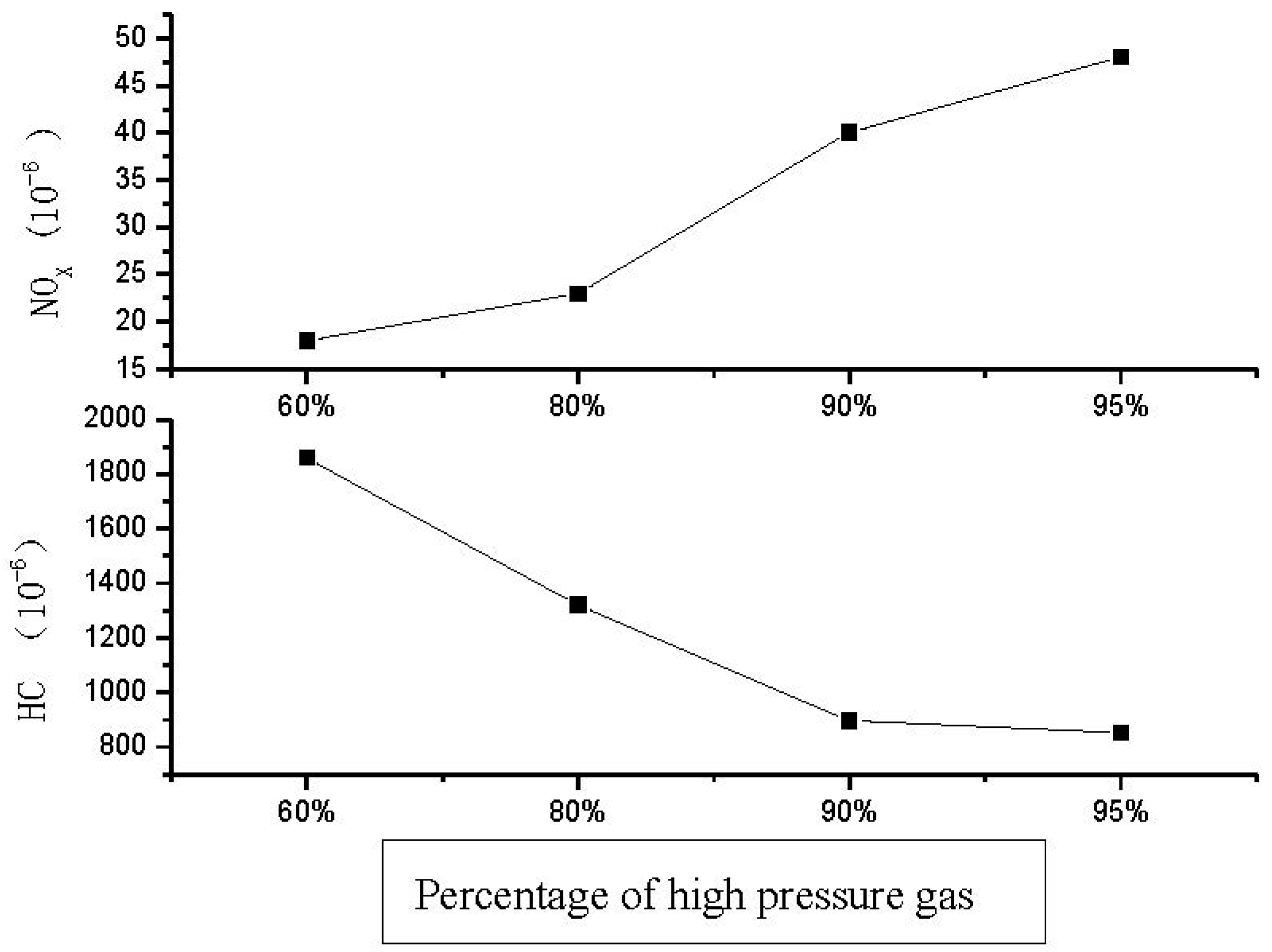
4.1. Impact of Ratios of High- and Low-Pressure Compound Gas Supply on Emission
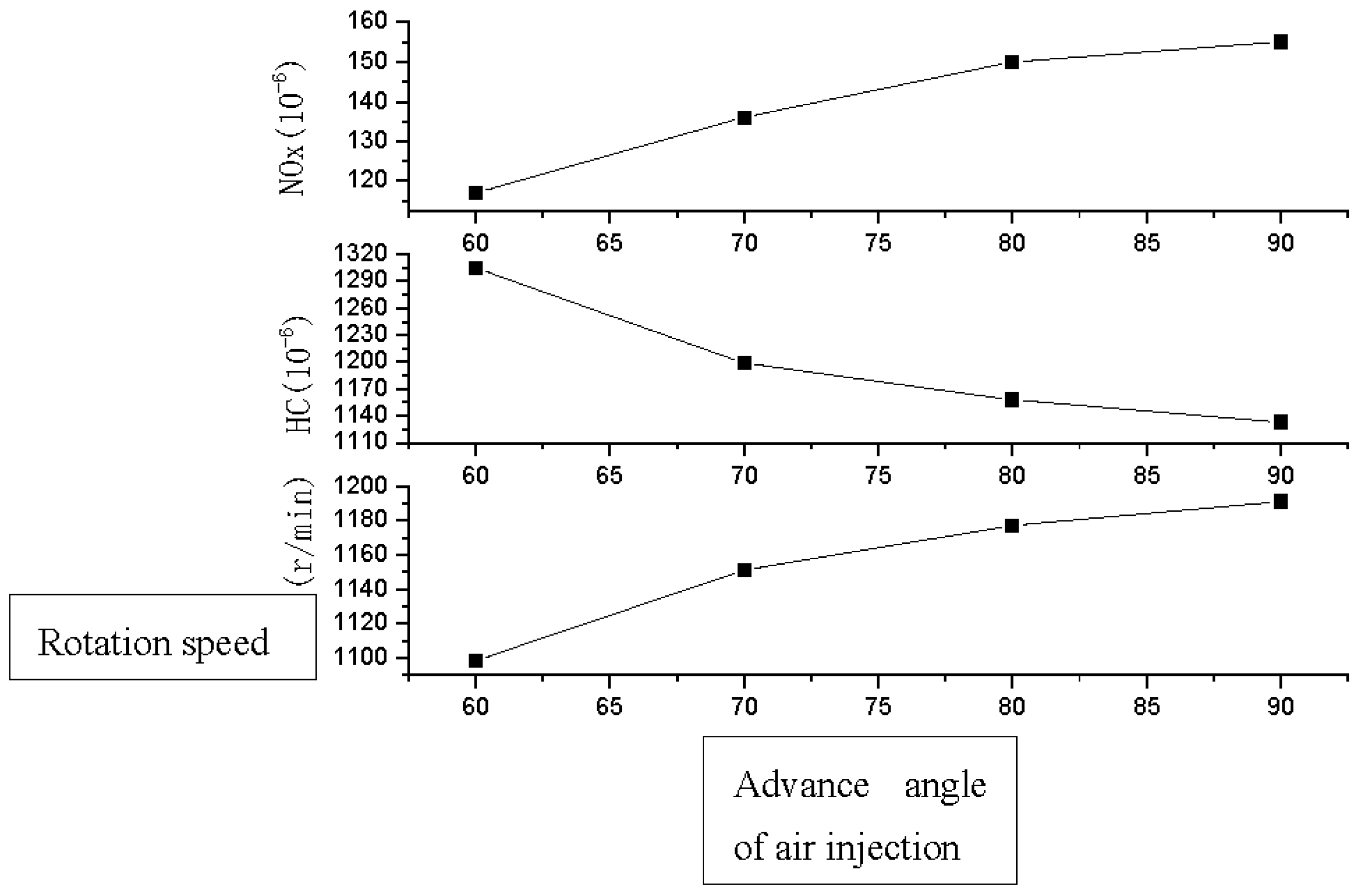
4.2. Impact of the Ignition Advance Angle on the Combustion Process
4.3. Impact of High-Pressure Gas Injection Time on Combustion Emission
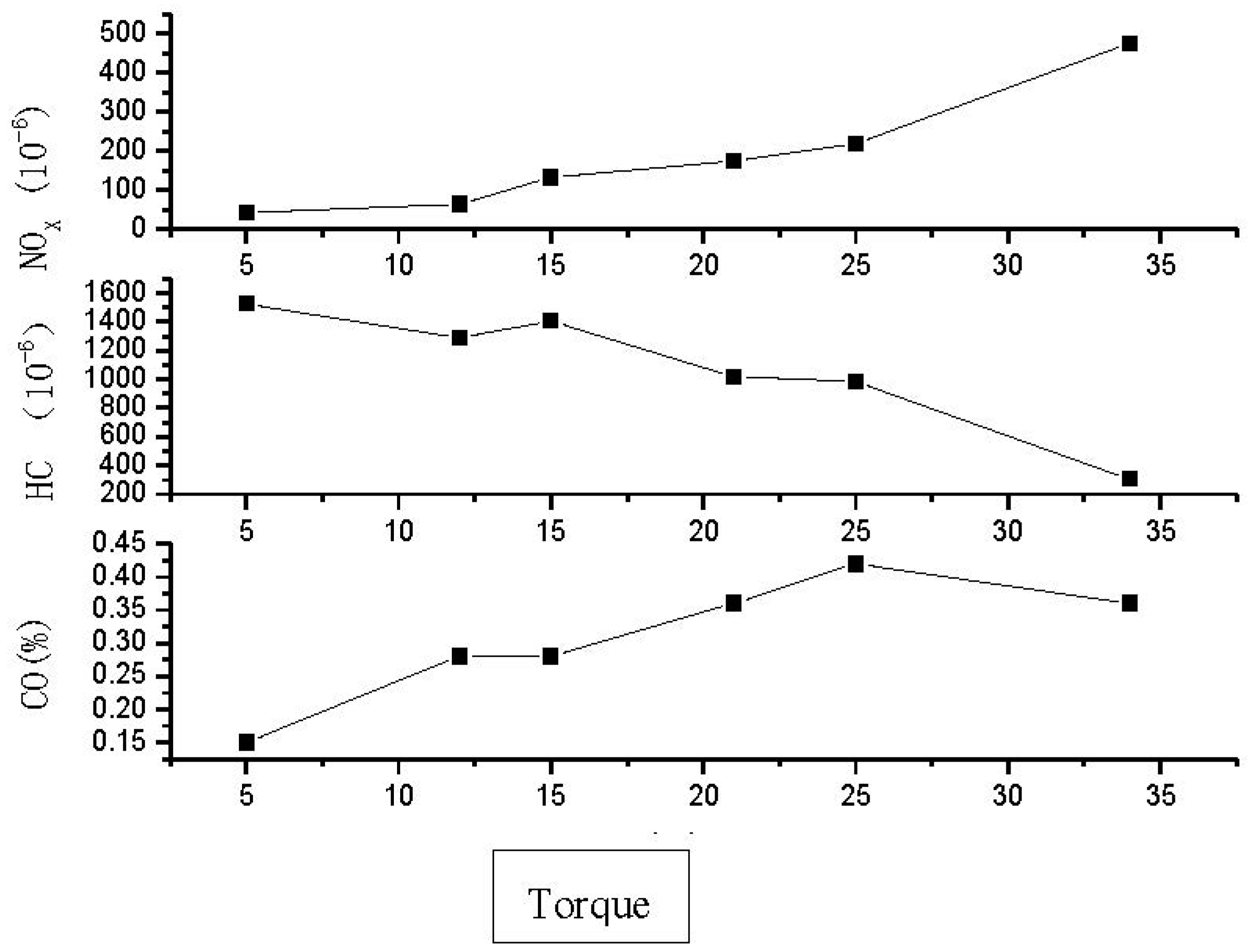
4.4. Load Characteristics of the Engine
5. Conclusions
- (1)
- During the study of the operating process of the spark-ignition natural gas engine, the impact of the ignition advance angle on the engine’s performance was analyzed and the best ignition advance angles under different conditions were determined.
- (2)
- The combustion conditions of high-pressure gas and low-pressure gas in the engine combustor varied greatly. The ratios of high-pressure gas and low-pressure gas both had great impacts on the performance and emission of the engine.
- (3)
- The shape of the main combustor has a great impact on the performance of the engine, that is, a shorter propagation distance can reduce the generation of HC. Reducing the diameter of the channels between the main and subsidiary combustors can enhance the stratification and facilitate the secondary ignition, thus achieving lean combustion in the main combustor and inhibiting the generation of NOX.
Author Contributions
Funding
Data Availability Statement
Conflicts of Interest
References
- Masotti, L. Vehicle to Grid Application in a Distributed Generation Medium Voltage Distribution Network. Master’s Thesis, School of Industrial and Information Engineering Energy Department, Jeonju, Republic of Korea, 2018. [Google Scholar]
- Warguła, Ł.; Kukla, M.; Lijewski, P.; Dobrzyński, M.; Markiewicz, F. Impact of Compressed Natural Gas (CNG) Fuel Systems in Small Engine Wood Chippers on Exhaust Emissions and Fuel Consumption. Energies 2020, 13, 6709. [Google Scholar] [CrossRef]
- Stettler, M.E.J.; Woo, M.; Ainalis, D.; Achurra-Gonzalez, P.; Speirs, J.; Cooper, J.; Lim, D.-H.; Brandon, N.; Hawkes, A. Review of Well-to-Wheel lifecycle emissions of liquefied natural gas heavy goods vehicles. Appl. Energy 2023, 333, 120511. [Google Scholar] [CrossRef]
- Kurien, C.; Varma, P.S.; Mittal, M. Effect of ammonia energy fractions on combustion stability and engine characteristics of gaseous (ammonia/methane) fuelled spark ignition engine. Int. J. Hydrogen Energy 2023, 48, 1391–1400. [Google Scholar] [CrossRef]
- Chen, H.; He, J.; Zhong, X. Engine combustion and emission fuelled with natural gas: A review. J. Energy Inst. 2019, 92, 1123–1136. [Google Scholar] [CrossRef]
- Rahimi, H.M.; Jazayeri, S.A.; Ebrahimi, M. Hydrogen energy share enhancement in a heavy duty diesel engine under RCCI combustion fueled with natural gas and diesel oil. Int. J. Hydrogen Energy 2020, 45, 17975–17991. [Google Scholar] [CrossRef]
- Ilhak, M.I.; Tangoz, S.; Akansu, S.O.; Kahraman, N. Alternative fuels for internal combustion engines. Future Int. Combust. Engines 2019, 36, 3389–3413. [Google Scholar]
- Boretti, A. Advantages and disadvantages of diesel single and dual-fuel engines. Front. Mech. Eng. 2019, 5, 64. [Google Scholar] [CrossRef]
- Dimaratos, A.; Toumasatos, Z.; Doulgeris, S.; Triantafyllopoulos, G.; Kontses, A.; Samaras, Z. Assessment of CO2 and NOx Emissions of One Diesel and One Bi-Fuel Gasoline/CNG Euro 6 Vehicles During Real-World Driving and Laboratory Testing. Front. Mech. Eng. 2019, 5, 62. [Google Scholar] [CrossRef]
- Putra, I.W.A.W.; Sukadana, I.G.K.; Tenaya, I.G.N.P.; Widiarta, I.P. The Effect of Types of Biogas and Methanol Purification and Loading as Fuel for Four-Stroke Generators on Exhaust Emissions. Nat. Sci. Eng. Technol. J. 2023, 3, 200–205. [Google Scholar]
- Wu, J. Development of Novel Catalytic Materials with Low Content of Precious Metals for the after-Treatment of Automobile Exhaust Gas. Master’s Thesis, Université de Lille, Lille, France, 2019. [Google Scholar]
- Gholami, A.; Jazayeri, S.A.; Esmaili, Q. A detail performance and CO2 emission analysis of a very large crude carrier propulsion system with the main engine running on dual fuel mode using hydrogen/diesel versus natural gas/diesel and conventional diesel engines. Process Saf. Environ. Prot. 2022, 163, 621–635. [Google Scholar] [CrossRef]
- Trivedi, S.; Prasad, R.; Mishra, A.; Kalam, A.; Yadav, P. Current scenario of CNG vehicular pollution and their possible abatement technologies: An overview. Environ. Sci. Pollut. Res. Int. 2020, 27, 39977–40000. [Google Scholar] [CrossRef] [PubMed]
- Ye, C.; Li, X.; Yu, X.; Zheng, M.; Xu, M. Effect of discharge current boost on ignition and combustion under cross flow conditions. Combust. Flame 2021, 223, 1–14. [Google Scholar] [CrossRef]
- Dias, B.M.D.A.; Laganá, A.A.M.; Justo, J.F.; Yoshioka, L.R.; Santos, M.M.D.; Gu, Z. Model-Based Development of an Engine Control Module for a Spark Ignition Engine. IEEE Access 2018, 6, 53638–53649. [Google Scholar] [CrossRef]
- Fan, B.; Pan, J.; Liu, Y.; Zhu, Y. Effects of ignition parameters on combustion process of a rotary engine fueled with natural gas. Energy Convers. Manag. 2015, 103, 218–234. [Google Scholar] [CrossRef]
- Li, M.; Wu, H.; Zhang, T.; Shen, B.; Zhang, Q.; Li, Z. A comprehensive review of pilot ignited high pressure direct injection natural gas engines: Factors affecting combustion, emissions and performance. Renew. Sustain. Energy Rev. 2020, 119, 109653. [Google Scholar] [CrossRef]
- Douville, B. Performance, Emissions and Combustion Characteristics of Natural Gas Fueling of Diesel Engines. Master’s Thesis, University of British Columbia, Vancouver, BC, Canada, 1994. [Google Scholar]
- Dumitrescu, S. Pilot Ignited High Pressure Direct Injection of Natural Gas Fueling of Diesel Engines. Ph.D. Thesis, University of British Columbia, Vancouver, BC, Canada, 1999. [Google Scholar]
- Trusca, B. High Pressure Direct Injection of Natural Gas and Hydrogen Fuel in a Diesel Engine. Master’s Thesis, University of British Columbia, Vancouver, BC, Canada, 2001. [Google Scholar]


| Port Number | Port Name | Color | Description |
|---|---|---|---|
| 1 | POWER | red | Positive electrode of power supply |
| 2 | GND | black | Negative electrode of power supply |
| 3 | VCC | orange | 5 V |
| 4 | IN | blue | TTL voltage, PWM signal |
| 5 | OUT | yellow | Injection valve drive signal |
| 6 | DRVGND | white | Injection valve drive power supply circuit |
Disclaimer/Publisher’s Note: The statements, opinions and data contained in all publications are solely those of the individual author(s) and contributor(s) and not of MDPI and/or the editor(s). MDPI and/or the editor(s) disclaim responsibility for any injury to people or property resulting from any ideas, methods, instructions or products referred to in the content. |
© 2023 by the authors. Licensee MDPI, Basel, Switzerland. This article is an open access article distributed under the terms and conditions of the Creative Commons Attribution (CC BY) license (https://creativecommons.org/licenses/by/4.0/).
Share and Cite
Zhu, Z.; Zhang, D.; Jiao, Y. Combustion Process of the Compound Supply CNG Engine. Processes 2023, 11, 2725. https://doi.org/10.3390/pr11092725
Zhu Z, Zhang D, Jiao Y. Combustion Process of the Compound Supply CNG Engine. Processes. 2023; 11(9):2725. https://doi.org/10.3390/pr11092725
Chicago/Turabian StyleZhu, Zhiqiang, Defu Zhang, and Yunjing Jiao. 2023. "Combustion Process of the Compound Supply CNG Engine" Processes 11, no. 9: 2725. https://doi.org/10.3390/pr11092725
APA StyleZhu, Z., Zhang, D., & Jiao, Y. (2023). Combustion Process of the Compound Supply CNG Engine. Processes, 11(9), 2725. https://doi.org/10.3390/pr11092725