Article

An Integrated Control Approach for Shifting Process of Single-Axis Parallel Hybrid Electric Vehicle with a Multi-Speed AMT Gearbox

1
Hubei Key Laboratory of Advanced Technology for Automotive Components, Wuhan University of Technology, Wuhan 430070, China
2
Foshan Xianhu Laboratory of the Advanced Energy Science and Technology Guangdong Laboratory, Foshan 528200, China
*
Author to whom correspondence should be addressed.
Processes 2023, 11(9), 2710; https://doi.org/10.3390/pr11092710
Submission received: 28 July 2023 / Revised: 1 September 2023 / Accepted: 7 September 2023 / Published: 11 September 2023

Abstract

:
When a single-axis parallel hybrid electric vehicle (HEV) equipped with a multi-speed AMT gearbox is in its shifting process, the superposition of dynamic characteristics of multiple power sources and the intervention and withdrawal of AMT transmissions can easily cause significant vehicle longitudinal jerk. To achieve rapid and smooth output changes during the shifting process, this paper proposes an integrated multi-stage robust shifting control method for a single-axis parallel hybrid electric vehicles with a multi-speed AMT gearbox. First, models of key driveline components are constructed, and the shifting process is divided into five stages to provide a clear description of the control problem. Subsequently, we reproduce an integrated multistage robust control method to achieve favorable switching performance and control robustness under external disturbances. We propose a data-driven model predictive control strategy based on additional constraints in the torque unloading and recovery phases. Simultaneously, we present a joint control algorithm that integrates the optimal control and disturbance suppression in the speed synchronization phase. In addition, we develop a sliding mode auto-disturbance rejection control algorithm to achieve accurate position tracking of the shift actuator in the pickup and engage phases. Finally, simulations and bench tests are carried out to verify the effectiveness of the robust control method under different driving conditions. The results demonstrate that the proposed control method can not only coordinate the torque across different power sources and clutch while minimizing vehicle longitudinal jerk, shift time, and friction work, but also provides apparent robustness to model uncertainties and external disturbance. Therefore, the proposed method may offer a theoretical reference for the actual vehicle controller during shifting.

1. Introduction

As the social economy and transportation logistics continue to develop, the demand for heavy commercial vehicles is steadily increasing. Since heavy commercial vehicles are massive, have high fuel consumption, and cover long distances, the need for energy savings and emissions reductions has become even more pressing. Hybrid system technology represents an important and breakthrough method for achieving energy savings and emissions reduction [1,2,3]. Recently, the single-axis parallel hybrid powertrain based on the automated mechanical transmission (AMT) has emerged as one of the mainstream hybrid powertrain configurations. This configuration has been widely adopted in heavy commercial vehicles due to its cost-effectiveness and outstanding environmental protection performance.
The reliability and drivability, which significantly affect the application of the system, are gaining increasing attention in practical engineering [4,5]. Among these aspects, shift control stands out as the core technology for dynamic coordination. It has a direct impact on the smoothness of vehicle output and greatly influences the driving experience for both the driver and passengers [6,7]. Improper control of torques from power sources and the clutch during the shifting process can lead to torque fluctuations in the output shaft, resulting in longitudinal jerk in the vehicle [8]. Therefore, ensuring the drivability of a single-axis parallel hybrid electric vehicle with a multi-speed AMT gearbox requires the design of an appropriate shift control strategy.
The shifting process is complex and involves multiple stages with short durations, as well as multiple objectives [9,10,11,12,13]. The controlled components encompass both the electric motor (EM) and the shifting motor, while the control objectives include jerk, shifting time, and the tracking accuracy of the angular displacement for the shifting motor. Numerous studies have been conducted to deal with the shift control problem. Qin et al. designed a shift control strategy based on the system’s structure and working modes. They adopted a motor/engine’s electronic throttle combined speed control strategy for engine drive mode, and a shift control strategy involving motor speed regulation without clutch disengagement for hybrid drive mode [14]. Wang et al. proposed a time-optimal shifting actuator control method. Experimental results demonstrated that this method can reduce shifting time and minimize shifting impact [15]. Sun et al. applied the theory of partial constant speed to segmentally process the engagement process of the clutch. They increased the clutch engagement rate when there was a significant speed difference between the master and slave clutch plates, and slowed down the engagement when the speed difference was small, thus reducing frictional losses [16]. Xia et al. presented a clutch control strategy to enhance the shift quality of power shift transmission and address the power cycle phenomenon during the shifting process. Test results showed that the proposed control strategy consistently maintains the driving disk’s rotational speed higher than that of the driven disk during clutch sliding and wear states [17]. Li et al. proposed a coordinated control strategy for both the combined clutch and the motor, utilizing linear quadratic optimal control to optimize the shifting process. This approach significantly reduces shift jerk and sliding friction work compared to pure clutch control [18]. Zhang et al. designed a multi-variable combined controller based on shifting actuator position, speed, and force control. They also developed a load torque observer to estimate system interference. This method can achieve both centralized and distributed coupled driving, minimizing the impact of shifting [19]. Wang et al. introduced a dual-loop self-learning fuzzy control method. In the inner loop control, they designed a fuzzy controller with a model reference self-learning algorithm. In the outer loop control, a self-learning rule based on fuzzy logic was designed to adjust the desired trajectory of the shift motor. This method enables smooth and rapid control of the shifting process [20].
The literature mentioned above provides important references for this study. However, the AMT examined in this article is a clutch-less and synchronizer-less system. Due to the absence of a synchronizer’s effect during the pickup and engagement stages, rapid motor unloading or poor motor speed synchronization ability can lead to shifting jerks [21,22]. A feedforward-feedback controller is introduced in [23] to achieve speed synchronization. Nevertheless, this controller necessitates extensive parameter calibration work, and its adaptability is limited due to the nonlinear constraints in response characteristics of core components. Alternative control methods, such as the flatness-based control approach [24], fuzzy control algorithms [25], genetic algorithms [26], and neuro-adaptive controllers based on radial basis function networks [27], have been employed to design adaptive control strategies. These methods often exhibit good robustness to the dynamic characteristics of nonlinear systems, but their application is constrained by the numerous required parameters. Quadratic optimal control, a widely-used approach, can address different optimization objectives under various control input constraints [28,29,30]. However, this optimal control algorithm is primarily open-loop, making it less adaptable to system changes [31]. Furthermore, this control method heavily relies on the model, which may not fully account for uncertain factors prevalent in actual industrial applications.
In fact, several factors, including time delays, overshoot in the actual power source, clutch and gearbox behaviors, parameter perturbations, and uncertain disturbances during the shifting process, can readily affect the accuracy of optimized control. In severe cases, these factors can even prevent the achievement of control objectives. Therefore, solving the problem of target trajectory for the power source and actuator under uncertain conditions is crucial for improving the practical control effectiveness of the optimal algorithm. Zeng et al. designed a state-feedback controller based on MPC theory to mitigate system jerk during the shifting process. The robustness of the control effect can be further enhanced through online rolling optimization, achieved by integrating feedback control and the predictive model [32]. Wu et al. presented an adaptive neural network control law with a sliding mode robust term and an adaptive neural network control law with a Hamilton-Jacobi inequality. The stability of the closed-loop system can be achieved based on the Lyapunov theory [33]. Hu et al. proposed a model-based nonlinear gearshift controller using the backstepping method to enhance the shift quality of vehicles equipped with a dual-clutch transmission (DCT). The robustness of the closed-loop error system is examined within the framework of input-to-state stability (ISS) theory, where model uncertainties are treated as additive disturbance inputs [34]. Shen et al. unified modeling errors, parameter perturbations, and external disturbances into a single disturbance term. They designed a sliding mode variable structure controller to achieve coordinated control of the engine, motor, and gear shifting actuator. This approach significantly reduced gear shifting shocks [35].
However, the aforementioned studies primarily concentrate on the control of single shift stages, lacking systematic research on the torque variation issue across the entire process, spanning from the torque reduction phase to the recovery phase. These findings are challenging to directly apply to the subject of this study. On one hand, the gearbox and clutch exhibit complex torque variation characteristics during the combination and separation process, with differences in torque control characteristics between the engine and motor, as well as variations in pressure control characteristics of the actuator. It is particularly challenging to develop an effective collaborative control mechanism for multiple power sources that enables the achievement of active compensation optimization, considering both smoothness and economy. On the other hand, in the actual vehicle operation process, whether it involves multiple working operations (such as starting, accelerating, and climbing) or encounters interference effects (such as model variations), these factors negatively impact the vehicle’s control performance. It is evident that these two issues constitute key factors affecting shifting quality and limiting shifting performance, representing the central challenges that require our attention. Enhancing the vehicle’s adaptability to cope with various working conditions and external interferences at each shift stage is a central issue in shift control. The primary focus of this study is to address these two problems, and the research holds significant importance and engineering value.
Motivated by the analysis above, this paper focuses on developing an integrated multi-stage robust shift control method for a single-axis parallel hybrid electric vehicle equipped with a multi-speed AMT gearbox. The objective of this method is to address the two problems mentioned earlier and ensure the robustness and adaptability of the shifting process. Firstly, we establish a dynamic model of the parallel hybrid powertrain and divide the shifting process into five stages, revealing the jerk problem arising during the shift. Subsequently, we propose an integrated multi-stage robust control method aimed at achieving smooth switching performance and control robustness even in the presence of external disturbances. Various targeted robust control schemes are introduced for different shifting phases, combining control methods such as model predictive control, sliding mode control theory, automatic perturbation rejection control, and perturbation observer techniques. Furthermore, we conduct simulations and bench tests to validate the effectiveness of the control method under different driving conditions.
The proposed integrated multistage robust control method in this paper incorporates several key features:
(1)
The data-driven model predictive control method is designed to combine system input and output data, enhancing anti-interference capability during the torque unloading and recovery phases;
(2)
Additionally, a P control and disturbance observer are employed to achieve reference speed tracking in the speed synchronization phase, even in the presence of external interference;
(3)
Furthermore, a new sliding mode active disturbance rejection control method is applied to improve the tracking accuracy and robustness of the sleeve displacement during the pickup and engage phase.
Overall, the research method in this study is highly relevant to addressing key issues. The contributions of the study mainly include the following aspects:
(1)
The development of a comprehensive driveline model, with special attention to the shift actuator, to enhance the accuracy of describing shifting problems.
(2)
In consideration of external disturbances and uncertainties in model parameters, a novel multistage control architecture integrating robust control methods is devised for each shifting stage. This architecture enables coordinated control of different power sources and clutches while reducing jerk in various driving conditions.
(3)
Simulation and bench tests are conducted to validate the effectiveness of the control method under different driving conditions. Various experimental results indicate that the proposed integrated robust control method effectively enhances vehicle adaptability across multiple working conditions and in the face of external interference at each shift stage. This research holds significant reference value for improving shifting robustness in similar vehicles.

2. Models and Problem Formulation

The design process studied in this article is shown in Figure 1.
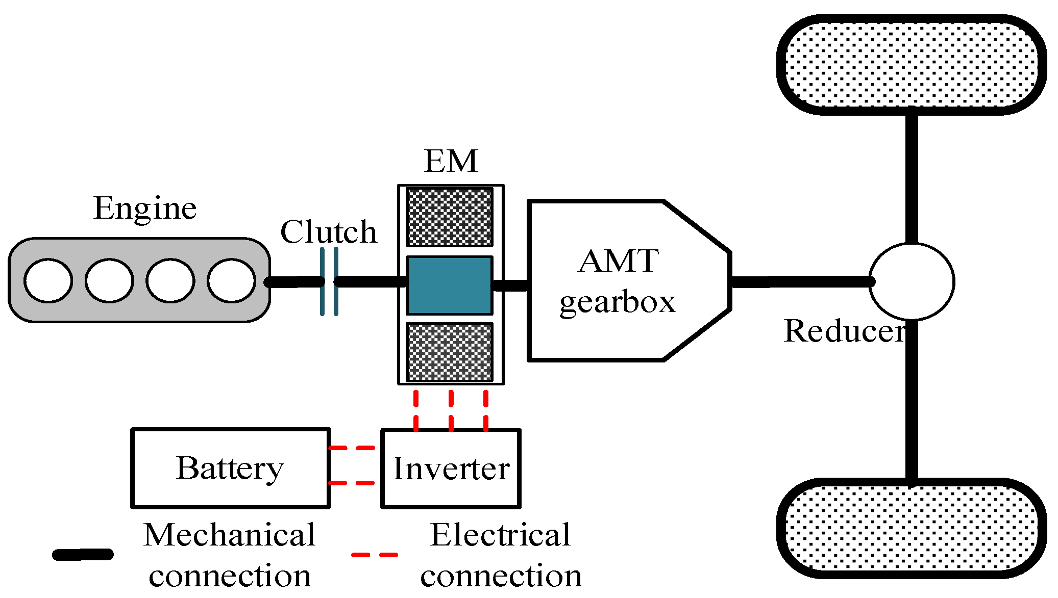
The configuration of single-axis parallel hybrid powertrain is illustrated in Figure 2. As shown in Figure 2, the EM is mounted between the clutch and AMT gearbox, and two power sources (engine and EM) can output the power on the same shaft during the driving process. The AMT can improve the adaptability of hybrid systems by adjusting the speed and torque of the EM, and the hybrid system can operate in the following driving modes based on operating conditions: electric driving mode, engine on driving mode (engine driving mode, hybrid driving mode, and engine active charging mode).

2.1. Driveline Modelling

Combined with the characteristics of single-axis parallel hybrid powertrain, the driveline model can be simplified as shown in Figure 3.
Models of the main components in the single-axis parallel hybrid powertrain involved in the shifting process are given in this section.
The engine is modeled by an inertia J e in which two torques act, the engine output torque T e , and the engine load torque T oute . The engine dynamic is modeled as:
J e ω ˙ e = T e T o u t e
where J e , ω e , T e and T oute represent the inertia moment of engine, the engine speed, the engine output torque and the engine load torque, respectively.
Similarly, the EM dynamics can also be modeled as:
J E M ω ˙ E M = T E M T o u t E M
where J EM , ω EM , T EM and T EM represent the inertia moment of EM, the EM speed, the EM output torque and the EM load torque, respectively.
The transmitted torque of the wet clutch in the sliding state is expressed as [36]:
T c l = 2 3 R 1 3 R 2 3 R 1 2 R 2 2 z μ k F c l s i g n ω E M ω e
where R 1 , R 2 , z , μ k , F cl represent the internal and outer radius of the contact surface between the master and slave plates, the numbers of clutch plates, the dynamic frictional coefficient, the pressing force on the clutch plates, respectively.
The torque transmitted by a wet clutch needs to be less than the maximum friction torque:
T c l , m a x = 2 3 R 1 3 R 2 3 R 1 2 R 2 2 z μ 0 F c l
where μ 0 represent the static frictional coefficient.
When the gearbox is in gear, the output torque of the AMT gearbox is shown as:
T A M T o u t = T o u t e + T E M J A M T ω ˙ E M × i A M T
where J AMT and i AMT represent the moment of inertia and transmission ratio of the AMT gearbox.
According to vehicle longitudinal dynamics, the load torque T load can be described as follows:
T l o a d = m g f cos α i n c + m g sin α i n c + 0.5 C D A f ρ V 2 R w i f d
where m , g , f , α inc , C D , A f , ρ , V , R w , and i fd represent vehicle mass, gravity, rolling resistance coefficient, incline angle, drag coefficient, vehicle frontal area, air density, vehicle speed, wheel radius, and final drive ratio, respectively.

2.2. AMT Actuating Mechanism Model

In this paper, the dynamics characteristic of AMT actuating mechanism is taken into consideration. The schematic diagram of electric actuating mechanism is shown in Figure 4.
The basic principle of the shift actuator is as follows: The transmission controller TCU adjusts the voltage of the shift motor to control the rotation of the shift motor to generate the required torque. The nut screw mechanism enables the conversion of shifting torque to shifting flat force, driving the shifting fork to move in a straight line, thereby achieving the separation and combination of the sleeve and gear ring. TCU collects the motor angular displacement in real-time through a shift angle sensor, thus closed-loop control of the displacement of the shift motor is achieved.
The voltage balance equation and torque balance equation of the shift motor are shown as [37]:
U m = R m i m + L m d i m d t + K e m f ω D C T m g r = K m i m = T L g r + J m ω ˙ D C + b m ω D C
where θ DC , U m , R m , L m , K emf , ω DC , T mgr , K m , i m , J m and b m represent angle, input voltage, internal resistance, equivalent inductance, induced electromotive force coefficient, speed, torque, torque coefficient, current, inertia moment, and rotational damping coefficient of shifting motor, respectively; T Lgr represents the load torque of shifting motor.
The screw drive nut to generate flat power. The kinematics relationship between the nut and the screw is shown as:
2 π ω D C = h v s F L = 2 π h T L g r
where F L , h and v s represent flat power, and lead axial movement speed, respectively.
The relationship between the angular displacement of the shifting motor and the displacement of the sleeve is:
θ ¨ D C = 2 π h x ¨ s = 2 π h v ¨ s
where θ DC and x s represent the angular displacement of the shifting motor and the displacement of the sleeve.
The output shifting force by the nut is:
F s h i f t = 1 μ n u t F L
where μ nut represents the resistance coefficient between nut and screw.

2.3. Control Problem Formulation

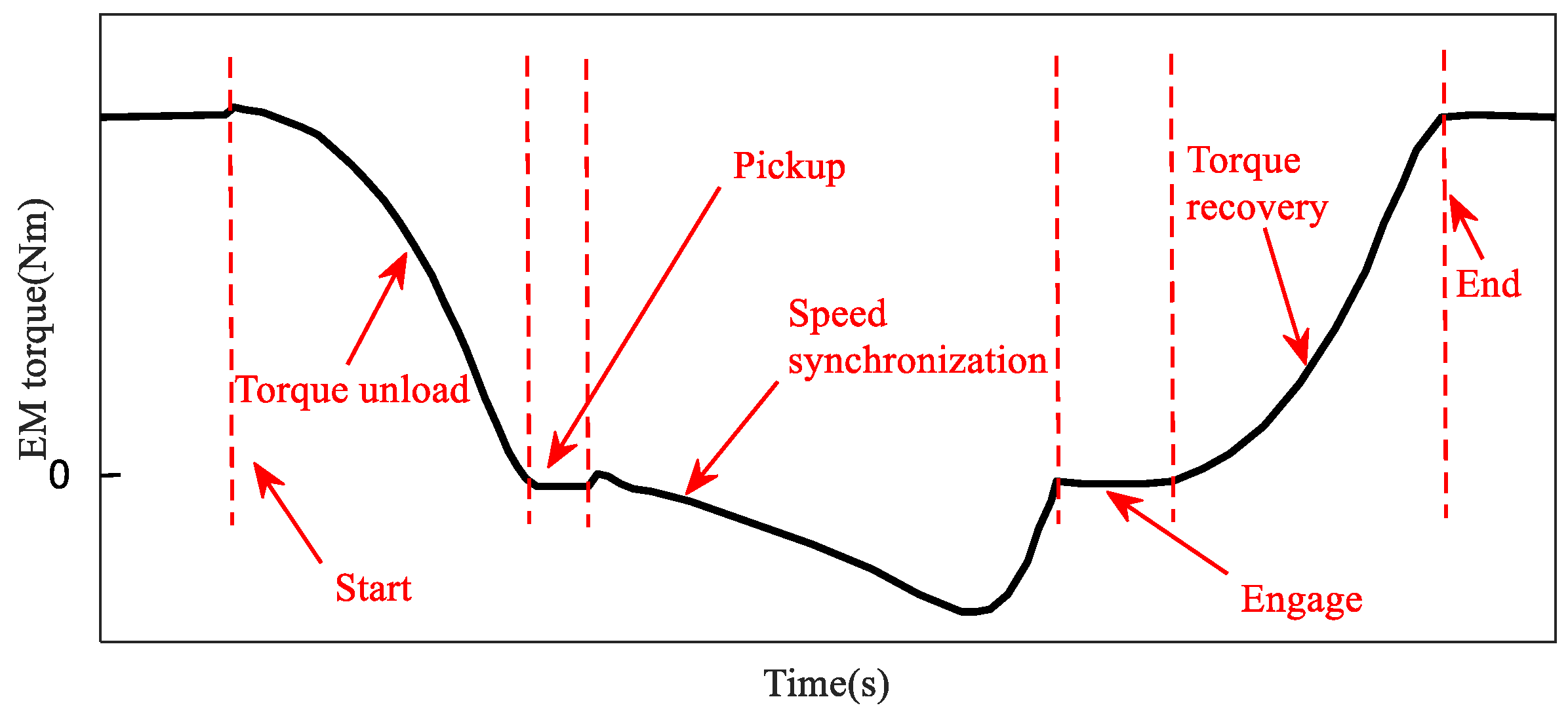
To describe the driveline model during the shifting process, this paper divides it into five phases, as shown in Table 1.
Combined with the stage division described in Table 1, the schematic diagram of the shifting process is shown in Figure 5, which using the torque variation process of an EM motor as an example. The key control issues for the different shifting phases are as follows:
(1)
During the torque unloading and recovery phase, it is necessary to coordinate and control the engine torque, motor MG1 torque, and clutch torque to prevent significant vehicle jerk.
(2)
During the speed synchronization phase, the AMT is in neutral and the connection between the EM and the transmission system is cut off. The control objective is to design efficient speed control algorithms to improve the speed accuracy of the EM and shorten the speed synchronization time.
(3)
During the pickup and engage phase, the shift actuator mainly functions, and the control core is to quickly track the target displacement of the sleeve to reduce tracking error of displacement. Therefore, it is necessary to adjust the shift force generated by the shift actuator to achieve closed-loop control of the sleeve displacement.
Furthermore, the controller should not only achieve stability control while considering different performance index constraints but also account for external disturbances from the actual transition system and uncertainties in the model structure and parameters to meet anti-interference robustness requirements.

3. Methods and Materials

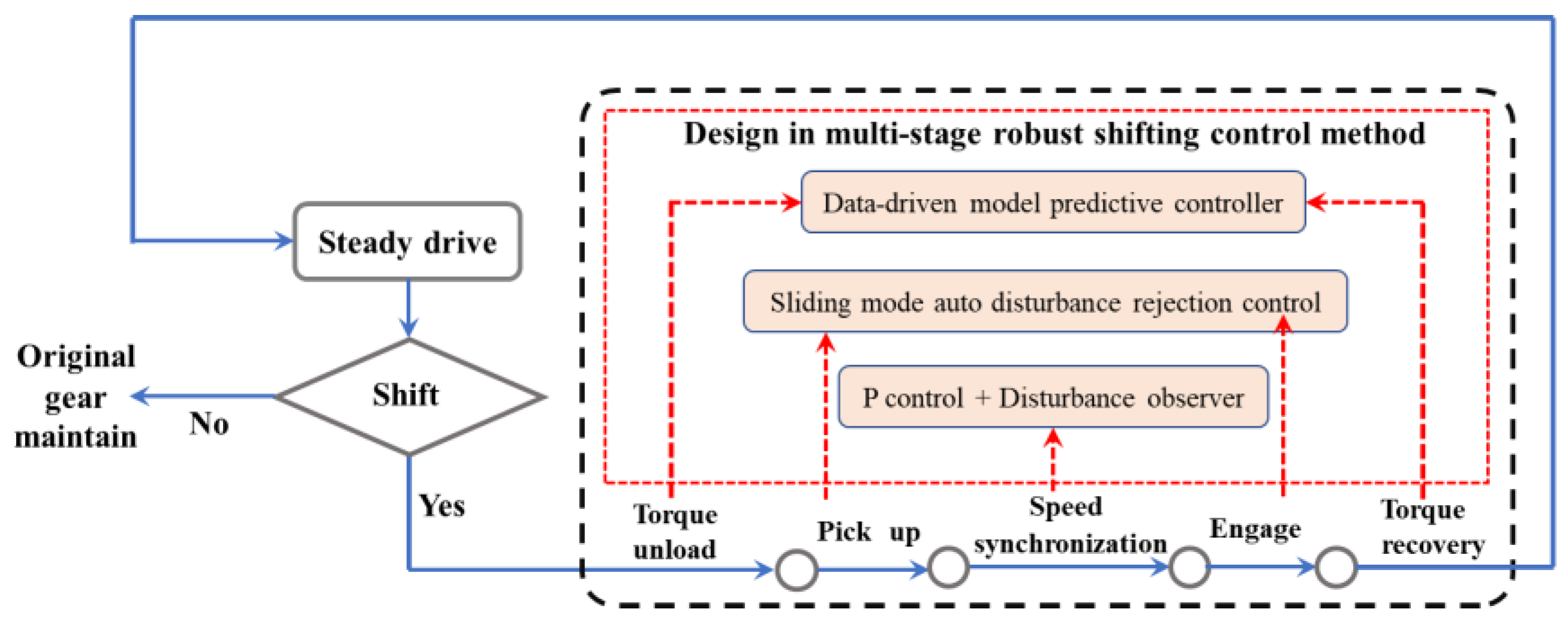
This section proposes a multi-stage robust control algorithm for the key control problems in different shift phases, in order to achieve orderly and coordinated control of the engine, EM, and AMT gearbox. The schematic diagram of the proposed multi-stage robust shifting control method is shown in Figure 6.

3.1. Data-Driven Model Predictive Control in Torque Unload and Recovery Phase

In the torque unloading and recovery phase, the system input and output data are combined to perform the subsystem identification to obtain the accurate model of the controlled object, which is combined with the model predictive control to form a data-driven model predictive control method. The principle of the method is shown in Figure 7.
First, the engine output torque, clutch torque, and motor output torque are used as control inputs, and the speed difference between the master and slave plates is used as the target output, the state space expression is written as follows:
x k + 1 = A x k + B u k y k = C x k + D u k u k = T e k T c l k T E M k y k = Δ ω = ω e ω c
where x(k) is the state variable; A, B, C and D are the coefficient matrices of state space expression.
Establishing a predictive model is crucial for designing the MPC controller [38,39]. The purpose of the prediction model is to forge the output trajectory similar to the reference output by solving the optimal control sequence at each moment. The derivation process of future state variables of the predictive model and subspace identification is referred to in Appendix A.
Next, to reduce stability static difference, the discrete model is converted into an incremental model:
Δ x k + 1 = A Δ x k + B Δ u k Δ y k = C Δ x k + D Δ u k Δ x k = x k x k 1 Δ u k = u k u k 1
The incremental prediction output expression is as follows:
Δ Y f = Γ N X f + H N d U f Δ Y p = Γ N X p + H N d U p Δ Y ^ f = L w Δ W p + L u Δ U f
Finally, the objective function part establishes the corresponding constrained optimization problem, and obtains the optimal control variable through the quadratic programming. The constrained objective function can be converted to a standard quadratic programming problem, as shown in Equation (14).
m i n Δ u f J = m i n Δ u f R e f k + 1 F L u I Δ u f T R e f k + 1 F L u I Δ u f + Δ u f T L a Δ u f = m i n Δ u f Δ u f T L u I T L u I + L a Δ u f 2 R e f k + 1 F T L u I Δ u f = m i n Δ u f Δ u f T H Δ u f + G T Δ u f
The system constraints are expressed as follows:
  u m i n k + j u k + j u m a x k + j , j = 0,1 , , N u 1 Δ u m i n k + j Δ u k + j Δ u m a x k + j , j = 0,1 , , N u 1 y m i n k + j y k + j y m a x k + j , j = 0,1 , , N p 1
where other matrix symbols are defined in Equation (16).
H = L u I T L u I + L a , G = R e f k + 1 F   L 1 = Δ u m i n k Δ u m i n k + 1 Δ u m i n k + N u 1 , L 2 = u m i n k u k 1 u m i n k + 1 u k 1 u m i n k + N u 1 u k 1   U 1 = Δ u m a x k Δ u m a x k + 1 Δ u m a x k + N u 1 , U 2 = u m a x k u k 1 u m a x k + 1 u k 1 u m a x k + N u 1 u k 1 , U 3 = y m a x k + 1 y m a x k + 2 y m a x k + N P L 3 = y m i n k + 1 y m i n k + 2 y m i n k + N P F , R = 1 0 0 1 1 0 0 1 1 1

3.2. P control and Disturbance Observer in Speed Synchronization Phase

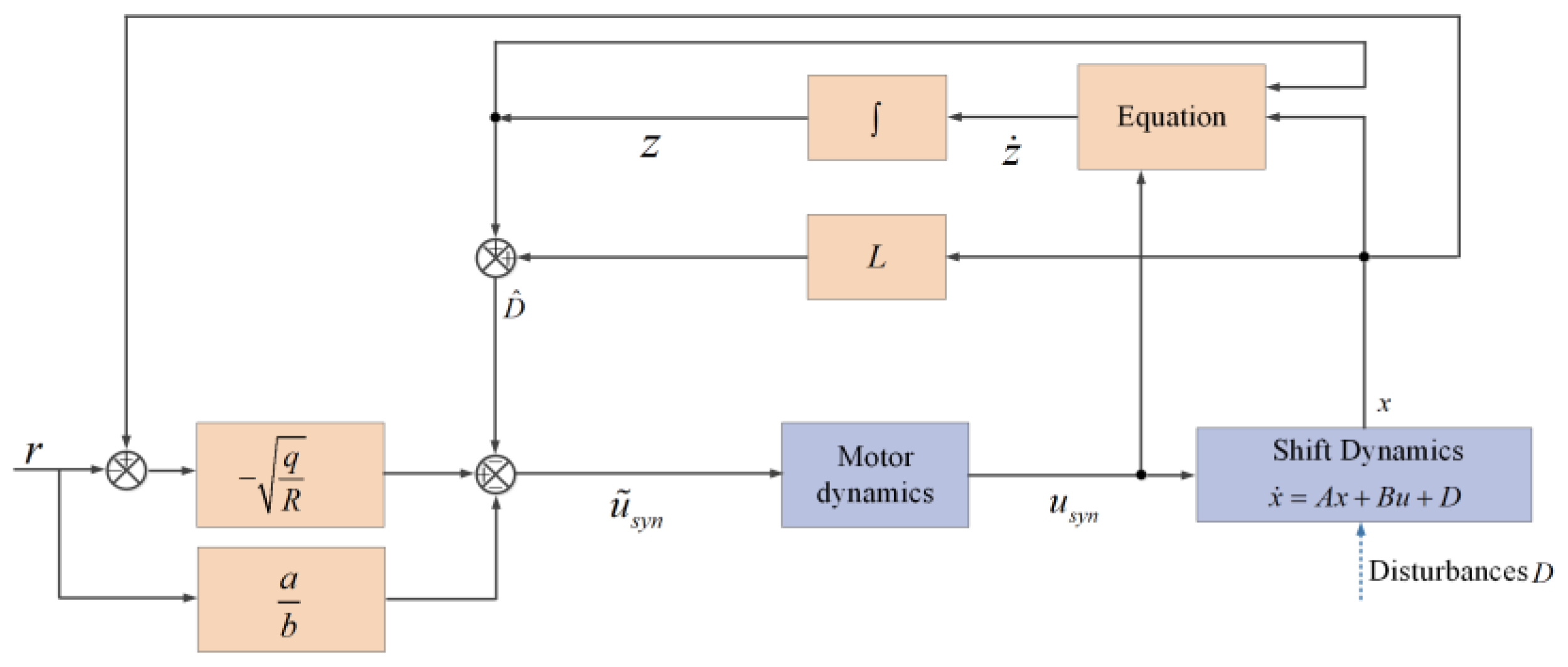
During the process of speed synchronization, the shaft where the motor is located is not mechanically connected to the wheel. The core goal of this process is to achieve tracking of the target speed. To ensure the tracking robustness of the controller, we designed an optimal control law design of the state space model with disturbance, the principle of the method is shown in Figure 8.
The system model is set as:
x ˙ = A x + B u + D
The cost performance function can be expressed as:
J = t 0 1 2 q ( x r ) 2 + 1 2 R u s y n 2 d t
where r is the reference signal, u syn is the control variable, q , R is the weight coefficient matrix.
Based on the derivation in Appendix B, the control law can be expressed as follows:
u ~ s y n = q R x r D ^ 1 a b r

3.3. Sliding Mode Active Disturbance Rejection Control in Pickup and Engage Phase

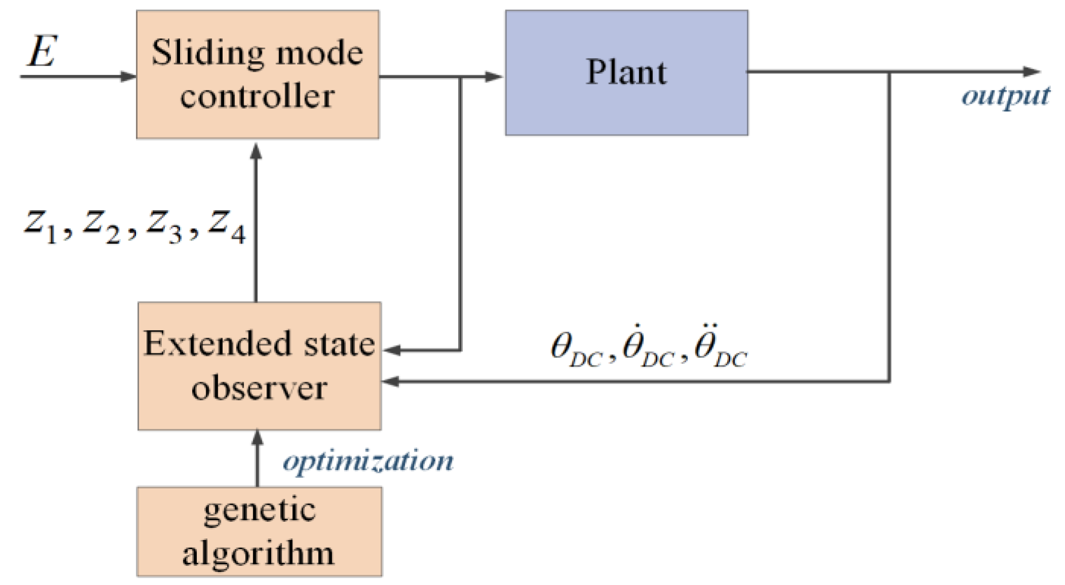
The shift actuator plays a major role in the phase of pickup and engage, and the control core is to quickly track the target displacement of the sleeve and reduce tracking errors. However, the uncertainty in internal parameters and external disturbances of the shift actuator increase the difficulty of system control, and even make the control ineffective in severe cases. To improve the tracking accuracy and robustness of the sleeve displacement, this section proposes a new sliding mode active disturbance rejection control algorithm, the principle of the method is shown in Figure 9.
Firstly, the state equation of the shift motor is established. The detailed process is provided in Appendix C.
Next, we design the extended observer. As the extended state observer incorporates external disturbances affecting the controlled object’s output as new state variables, for the third-order system in this paper, its extended observer form is of fourth order:
e = z 1 x 1 z ˙ 1 = z 2 β 01 e z ˙ 2 = z 3 β 02 f a l ( e , α 1 , δ ) z ˙ 3 = z 4 + f ( z 2 , z 3 ) β 03 f a l ( e , α 2 , δ ) + b u z ˙ 4 = β 04 f a l ( e , α 3 , δ )
where z 4 is the observed value of the external total disturbance.
Since the variables z 1 , z 2 , and z 3 are estimates of the state variables x 1 , x 2 , and x 3 , when designing the sliding mode controller, x 1 , x 2 , and x 3 can be replaced by z 1 , z 2 , and z 3 , that is, the sliding mode controller can be redesigned using the state variables observed by the extended state observer and the external total disturbance, which can significantly enhance the robustness of the control algorithm.
For the fourth-order extended state observer, the four core parameters β 01 , β 02 , β 03 , and β 04 need to be selected. To improve the tuning efficiency of core parameters, this section conducts optimization research on observer parameters based on genetic algorithms [40]. The design process is as follows:
(1)
Encode the initial population of key parameters β 01 , β 02 , β 03 , and β 04 .
(2)
Evaluate the individual fitness value in the population, and set the objective function as the fitness function. To obtain a good observation effect, this paper selects the integral of time weighted absolute value of the error as the fitness function:
I T A E = 0 t e E S O t d t
where e ESO is the error between the estimated value and the actual value.
(3)
Select the best individual from the initial population for crossover and mutation operations to determine whether the iteration termination conditions are met. If satisfied, the optimal parameters are output. If not, continue to select regenerated individuals and perform crossover and mutation operations with a certain probability to generate a new generation of population, and return to step (2).
Finally, we design a sliding mode controller. Define the angular displacement tracking error of the shift motor as:
E = Z m X m d = e , e ˙ , e ¨ T = e 1 , e 2 , e 3
where Z m is the observed state variable, Z m = z 1 , z 2 , z 3 ; X md is the set value of motor angular displacement, X md = x d , 0 , 0 .
The sliding surface function is set to:
s 1 = d d t + N s 3 1 e = N s 2 e + 2 N s e ˙ + e ¨ = N s 2 e 1 + 2 N s e 2 + e 3
The output of the sliding mode controller is solved by combining the equivalent control law with the arrival control law.
Taking the derivative of the sliding surface function yields:
s ˙ 1 = N s 2 e 2 + N s e 3 + e ˙ 3
Bringing Equation (A21) into Equation (24) yields:
s ˙ 1 = N s 2 e 2 + N s e 3 + b m z 2 + a m z 3 + c m U m + d m z 4 = 0
The equivalent control law u e q 1 of sliding mode control is:
u e q 1 = U m = 1 c m N s 2 e 2 N s e 3 b m z 2 a m z 3 z 4
Innovate switching control law u s w 1 to stabilize the system trajectory on the sliding mode surface.
To solve the chattering problem caused by symbolic functions, hyperbolic tangent functions are used instead of traditional symbolic functions:
u s w 1 = η 1 t a n h s 1
Combining the equivalent control law with the arrival control law, the sliding mode control law is:
u 1 = u e q 1 + u s w 1 = 1 c m N s 2 e 2 N s e 3 b m z 2 a m z 3 d m z 4 η 3 t a n h s 3
Finally, the stability of sliding mode active disturbance rejection controller is validated. The detailed process is described in Appendix D.

4. Results and Discussion

This section analyzes the control method results in simulation and bench test, and discusses the contribution of the results.

4.1. Basic Settings

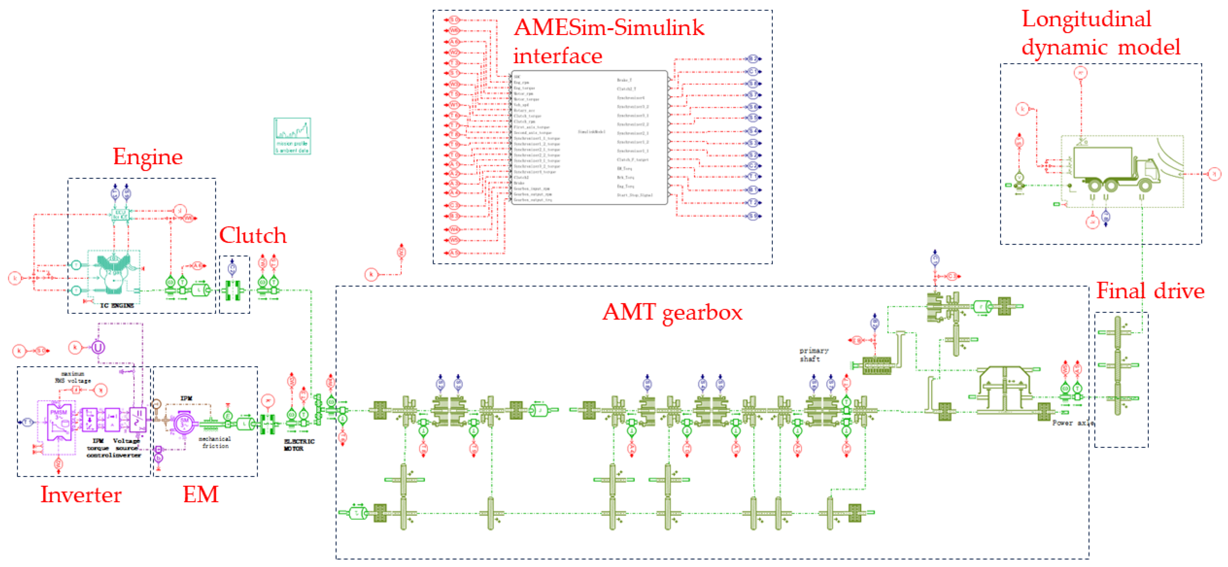
The diagram of the co-simulation platform is shown in Figure 10. The AMESim model includes engine, clutch, EM, AMT gearbox, final drive, and longitudinal dynamic model. The robust shift control strategy is established in the MATLAB/Simulink environment. The AMESim and MATLAB/Simulink co-simulation platform achieves information interaction through simulation interface.
The co-simulation of AMESim and MATLAB/Simulink is conducted based on the parameters of the studied hybrid powertrain (Table 2).
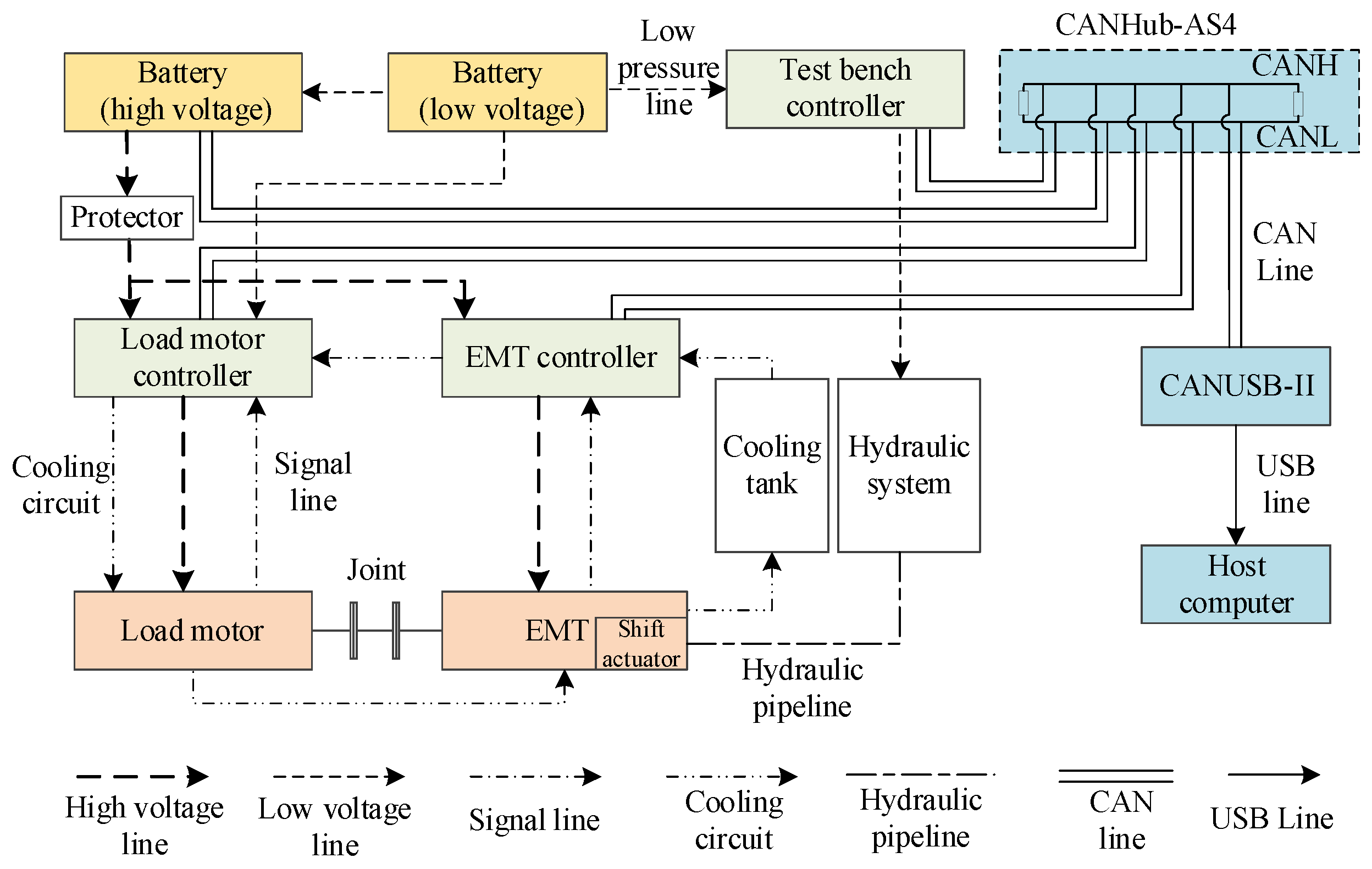
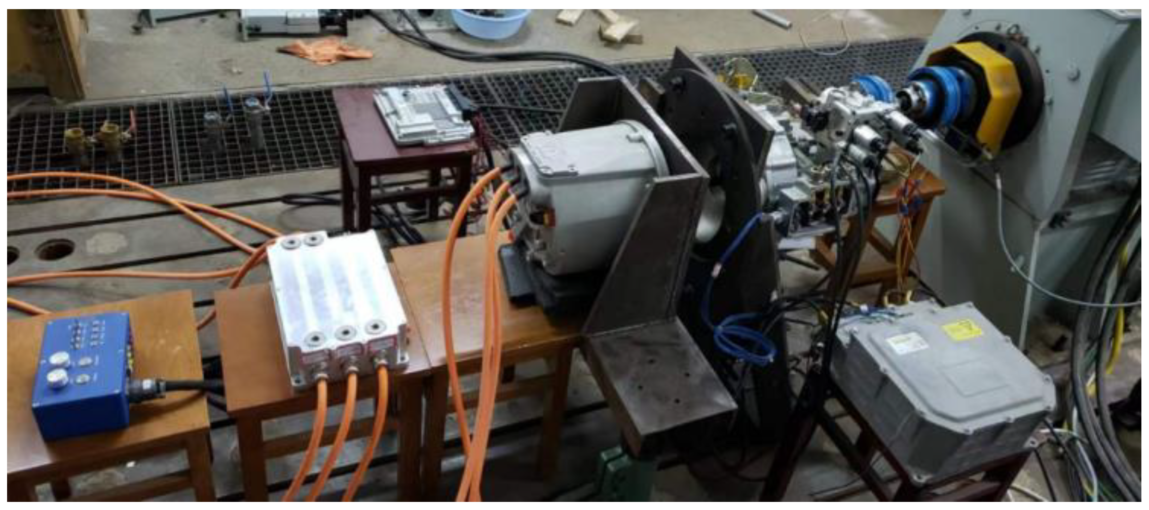
The test bench for the single-axis parallel hybrid electric vehicle with a multi-speed AMT gearbox in the shifting process was built as depicted in Figure 11 and Figure 12.
The main components of the test bench include the controller of test bench, EMT, the load motor, the EMT controller, the load motor controller, the hydraulic pipeline system, the low-voltage and high-voltage battery, the cooling tank, etc. The test bench controller receives CAN messages from the battery system, load motor, and the EMT, and collects sensor signals through the I/O interface. The current state of the test bench is judged and analyzed, and the overall control of the test bench is achieved by sending the CAN messages and outputting electrical signals. Specifically, the CAN bus system consists of CANUSB-II intelligent CAN card, CANHub AS4 optocoupler isolator, and twisted pair with shielded wire. The test bench controller receives the analog voltage output by the rotary potentiometer, converts it into the corresponding speed of the load motor, and sends a CAN message to the load motor controller. After receiving the CAN message from the test bench controller, the load motor controller controls the load motor accordingly, and feedback the state information of the load motor and load motor controller to the test bench controller through the CAN message. The EMT system includes the shift actuator, gear transmission system, and motor system. The motor controller responds to the commands of the test bench controller and feedback the state information of motor to the test bench controller through CAN messages.

4.2. Simulation Results and Discussion

First, analyze the control performance of gear shifting under 0 slope and load-free conditions.
Simulation condition 1 features the following settings: shifting from 4th gear to 5th gear; EM starts the engine through the clutch. Figure 13 present the upshift simulation results under simulation condition 1. The results present (a) no active control, (b) PID control, and (c) IMSR control.
In the absence of active control, the jerk during the shifting process occurs mainly during the torque unloading, engaging, and torque recovery phases. The maximum jerk of the vehicle is −19.83 m/s3, slightly above the national recommended value; the shift time is mostly consumed during the speed synchronization and torque recovery processes. PID control is applied to the speed synchronization process, under the PID speed control of the motor, the input shaft speed of the transmission quickly reaches the target speed value, and the maximum jerk of the vehicle is −15.36 m/s3. Compared to the above no active control and PID control, IMSR control takes the speed difference between the clutch master/slave plates as the control objective, and controls input signals such as engine torque, clutch torque, and motor torque, which can more smoothly control the engine torque and speed, ensuring less jerk and shift time during the shift process. The maximum jerk of the vehicle is −7.58 m/s3.
Table 3 shows the comparison results for the shift time and jerk. It can be concluded that the PID control shortens the synchronization time and reduces the shift jerk during the speed synchronization compared to no control. However, it achieves poor control of the engine torque during torque recovery, with larger jerk and longer shift time; the IMSR control has better control performance for engine torque, motor torque, and clutch torque under the entire shift process, with shorter shift time and lower jerk.
Based on the results of simulation 1, the proposed method solves the first problem described in this study, which achieves the entire process from torque reduction phase to recovery phase through coordinated control of the power source, execution mechanism control, and motor control. The method achieves active compensation optimization and have favorable control performance.
Second, we analyze the control performance of gear shifting under climbing and load conditions to improve the validation of different working conditions.
Simulation condition 2 features the following settings: heavy and light load climbing cycles. Under the heavy load climbing condition, the vehicle has a mass of 25,000 kg and a road slope of 5 degree. The simulation results are shown in Figure 14. The total shifting time is 350 ms. It can be observed that the engine output torque under heavy load conditions is significantly higher than the standard operating conditions in Section 4.1. The speed synchronization phase is sustained for 60 ms, and the active synchronization function of the motor operates normally during the torque recovery phase. The maximum vehicle jerk under heavy load conditions is 8.53 m/s3, which indicates that the IMSR control effect can also adapt to heavy load conditions normally.
Under the light load climbing condition, the vehicle mass is 9200 kg and the road slope is 5 degrees. The simulation results are shown in Figure 15. The total shifting time is 420 ms. Under light load conditions, the engine torque is significantly lower than the standard operating conditions in Section 4.1. The vehicle jerks during light load shifting are greater than in standard and heavy load conditions. The speed synchronization phase is sustained for 60 ms, which is consistent with the standard operating conditions. The active speed synchronization is normal, with a maximum impact of 9.56 m/s3. It can be seen that the IMSR control algorithm has similar control effect on single-axis parallel hybrid vehicles equipped with AMT under different operating conditions.
Based on the results of simulation 2, the proposed method solves the second problem described in this study. When the operating conditions change, it can still maintain the expected control performance through adaptive adjustment of control parameters, and the overall jerk is limited to the small range. It is of great significance for the stable operation of vehicles under multiple working conditions.
Third, an interference model is added in order to further validate the performance of the controller.
Simulation condition 3 features the following settings: pickup; the reference value for angular displacement of the shift motor is 10 rad. Due to internal parameter changes and external disturbances in the shift actuator, the anti-interference performance of the control algorithm with a given motor angular displacement expected curve will be tested under the two simulation conditions. One is that the parameters of the shifting motor mechanism are reduced by 10% during operation; shift resistance value is disturbed by Gaussian white noise. Another is that the shift resistance value is interfered by Gaussian white noise. Figure 16 and Figure 17 present the upshift simulation results obtained for the control strategies of PID and IMSR under simulation condition 3, respectively. The parameter values of the sliding mode active disturbance rejection controller are: β 01 = 90 , β 02 = 350 , β 03 = 1145 , β 04 = 7934 , N s = 40 , η 1 = 0.68 .
From Figure 16, it can be seen that the sliding mode active disturbance rejection controller is better able to cope with the internal parameter changes, and basically maintains the original tracking control performance, while the PID controller shows more pronounced overshoot. From Figure 11, we can see that in the presence of adversarial noise interference, the sliding-mode active perturbation rejection controller basically ensures stable tracking of the target trajectory, while the PID controller exhibits oscillations of varying degrees.
Based on the results of simulation 3, this method solves the second problem described in this study. The method can ensure the stability of the entire shift process through predictive model feedback, disturbance observer, and sliding mode control methods when the system is subject to external interference. This provides a fundamental guarantee for the application of the method in practical products and is a key contribution of this study.
Finally, further discussion will be conducted on the simulation results. In this study, the core issues that need to be addressed include two points:
(1)
How to develop an effective collaborative control mechanism for multi power source that enables active compensation optimization that considers both smoothness and economy.
In response to this challenge, we have analyzed the characteristics of the shift process and designed appropriate methods to solve the problem. The purpose is to verify the good control effect of the method in this section through reasonable simulation assumptions.
(2)
In real-world vehicle operations, factors such as various working conditions (starting, accelerating, climbing, etc.) and interference effects (model uncertainties) can negatively impact vehicle control performance.
To address this issue, we have considered the adaptability and robustness in the design of the method. In this section, Simulation 2 involved assumptions and validations under changing operating conditions, while Simulation 3 dealt with assumptions and validations when the shift actuator’s parameters were altered. The results of both simulations consistently demonstrate the method’s effectiveness.

4.3. Test Results and Discussion

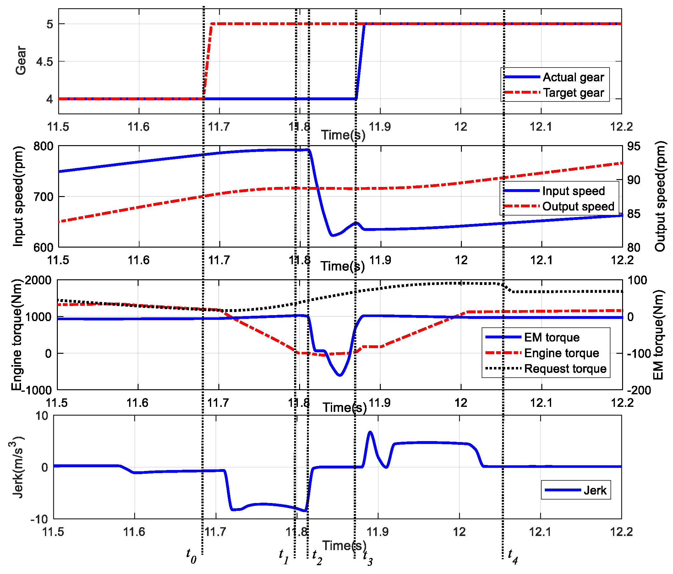
The IMSR control test results under acceleration and deceleration conditions are shown in Figure 18.
The results show that the IMSR control strategy can meet the vehicle control requirements. During the starting process, pure electric drive mode is adopted, and when the vehicle speed rises to a certain value, it switches to engine drive mode; The shifting time during the acceleration process is greater than that during the deceleration process. The jerk during the acceleration and deceleration process is less than 10 m/s3.
The statistical indicator results of different control algorithms are shown in Table 4, Table 5 and Table 6. The PID control can accelerate the synchronization of input shaft speed, shorten the synchronization time, and reduce vehicle jerk. However, due to the lack of engine speed control, the torque recovery process still takes a long time, and the improvement of jerk and friction work is not significant. The IMSR control results indicate that by controlling input parameters such as engine torque, the engagement time of the clutch during the torque recovery process can be effectively shortened, and the improvement of vehicle jerk and friction work is significant. The maximum jerk is 8.13 m/s3, and the average friction work is reduced by about 96.7%.
When compared to simulation environments, bench tests closely resemble real vehicle conditions, presenting greater challenges for verifying the effectiveness of the control method. Unlike previous simulation studies, the bench test involved a more extensive number of shift processes and conducted a comprehensive evaluation of shift time, jerk, and friction work. This comprehensive testing provided a more thorough verification of the method.
Based on the test results, the proposed control method, in contrast to traditional PID control, consistently delivers shorter shift times and reduces jerk and sliding work across various shift processes. Consequently, the method exhibits enhanced adaptability and robustness under diverse working conditions during different shift processes, forming a crucial foundation for its potential application in real vehicles.

5. Conclusions

To mitigate the negative impact of multiple operating conditions and external disturbances on vehicle smoothness during the entire shift process from torque reduction phase to recovery phase, an integrated multistage robust control method is proposed in this paper. First, First, we analyze the dynamic plant model and formulate the control problem to enhance the accuracy of describing different shifting phases. Subsequently, we introduce a data-driven model predictive control strategy based on additional constraints at the stage of torque unloading and recovery phase. The combined control algorithm that integrates the optimal control and disturbance suppression has been presented at the stage of speed synchronization phase. The sliding mode auto-disturbance rejection control algorithm is developed to achieve precise position tracking of shift actuator at the stage of pickup and engage phase. Finally, the results and relevant discussion are presented. Compared to the case with no active control, the jerk produced by the proposed method decreases from −19.83 m/s3 to −7.58 m/s3, resulting in a substantial improvement of 61.8%, and the improvement of anti-jerk is 22.5% under PID control. Additionally, the total shift time resulting from the proposed method is also significantly smaller than the no active control and PID control, with the significant improvement of 53.4% and 39.3%. Furthermore, under different loading conditions, the maximum vehicle jerk can be reduced to less than 10 m/s3, and the speed synchronization time can be shortened to 60 ms, which reflects the strong robustness of the method. This finding signifies that the control effect is consistent and that the controller is suitable for the common operating conditions of commercial vehicles.
In addition to the aforementioned contributions, this study establishes a test base through the development of a self-developed test bench. The bench test results indicate that the two problems mentioned in the introduction have been successfully addressed, and the proposed method is applicable not only to the shifting process but also to unsteady operational processes such as mode transitions.
However, the method in this study primarily concentrates on configuring operating conditions within the simulation environment and constructing a test bench for validation. Nevertheless, the real vehicle verification is still pending. In the next step, experimental verification will be conducted on prototype vehicles, and the impact of other facts (such as driver intention, shifting rules and the power source torque change rate limit) on the jerk of the powertrain will be investigated. This effort aims to further enhance the driving comfort of the single-axis parallel hybrid electric vehicle.

Author Contributions

Theoretical framework, validation and writing original draft preparation, C.H.; review, editing and project administration, C.D. All authors have read and agreed to the published version of the manuscript.

Funding

This research was funded by the National Natural Science Foundation of China (No. 51975434, 51775393) and Key R&D project of Hubei Province, China (2022BAA074).

Data Availability Statement

Not applicable.

Conflicts of Interest

The authors declare no conflict of interest.

Appendix A

The future state variables of the predictive model are derived, as shown in Equations (A1) and (A2).
y N y N + 1 y N + j 1 y N + 1 y N + 2 y N + j y N + 2 y N + 3 y N + j + 1 y 2 N 1 y 2 N y 2 N + j 2 = C C A C A 2 C A N 1 x N x N 1 x N + j 1 + D 0 0 0 C B D 0 0 C A B C B D 0 C A N 2 B C A N 3 B C A N 4 B D u N u N + 1 u N + j 1 u N + 1 u N + 2 u N + j u N + 2 u N + 3 u N + j + 1 u 2 N 1 u 2 N u 2 N + j 2
x N x N 1 x N + j 1 = A N x 0 x 1 x j 1 + A N 1 B A N 2 B B u 0 u 1 u j 1 u 1 u 2 u j u N 1 u N u N + j 2
Equations (A1) and (A2) can be further expressed as follows:
Y f = Γ N X f + H N d U f Y p = Γ N X p + H N d U p X f = A N X p + Δ N d U p
where U p , U f , X p and X f are the input data matrices and state data matrices generated before and after the system input excitation, which can be used to obtain subspace prediction factors. p represents the data before the current time, and f represents the data after the current time.
The predict output can be expressed as:
Y f = L w W p + L u U f
where L w is the coefficient matrix of the past input output matrix W p and L u is the coefficient matrix of the future input sequence. Among them,
W p = Y p U p
Using the least squares method to solve the optimal solution of the following equation to obtain the coefficient matrix L w and L u of the subspace prediction, and identify the system model:
m i n L w , L u Y f L w L u W p U f 2
Obtain the prediction factor for the subspace:
L w L u = Y f W p U f = Y f W p T U f T W p U f W p U f 1

Appendix B

The optimal control u syn consists of the optimal state trajectory x * , reference signal r , and disturbance D , in order to minimize the Equation (18), the optimal control expression is:
u * = q R x r D b
From the Equation (A8), it can be seen that the optimal control law consists of two components: the first part is proportional control, and the second part is disturbance compensation.
The tracking error and are defined as:
e = x r e ˙ = x ˙ = a e + r + b u s y n + D = α e + a r
Among them, α is a constant, and its expression is:
α = a b q R
To eliminate stability errors, Equation (A8) can be modified as follows:
u ~ s y n = u s y n a b r = q R x r D b a b r
Although Equation (A8) has a simple and intuitive form, it is still necessary to determine the values of q and R before final application. If these two weights can be associated with certain performance indicators, their values will be easily determined. The tracking error of the control law is:
e t = e 0 e α t
The time required for tracking error to decrease from e 0 to a certain value of E   ( E > 0 ) is:
t T T S = ln E ln e 0 α
Equation (A8) is rewritten as
u ~ s y n = q R x r D 1 a b r
In order to estimate D 1 , the observer is designed as follows:
z ˙ = L b ( z + L x ) L ( a x + b u ) d ^ 1 = z + L x
where L is the gain of the observer.
Define the disturbance estimation error as:
e d = d ^ 1 d 1 e ˙ d = L b e d D ˙ 1
The final control law is given by the following equation:
u ~ s y n = q R x r D ^ 1 a b r

Appendix C

Equation (7) is organized into Equation (A18):
U m = R m K m T L g r + J m θ ¨ D C + b m θ ˙ D C + L m K m J m θ D C + b m θ ¨ D C + K e m f θ ˙ D C
The calculation formula for load torque is:
T L g r = m s h 2 4 π 2 1 μ n u t θ ¨ D C + h 2 π 1 μ n u t F f
Therefore, Equation (A18) can be reorganized as:
U m = R m K m h 2 π 1 μ n u t F f + m s h 2 4 π 2 1 μ n u t + J m θ ¨ D C + b m θ ˙ D C + L m K m J m θ D C + b m θ ¨ D C + K e m f θ ˙ D C
Simplifying Equation (A20) yields:
θ D C = a m θ ¨ D C + b m θ ˙ D C + c m U m + d m T L 1
Define the state variable of shift motor as:
X m = θ D C , θ ˙ D C , θ ¨ D C T = x 1 , x 2 , x 3 T
The state space equation of the shift motor is expressed as:
x ˙ 1 , x ˙ 2 , x ˙ 3 T = 0 1 0 0 0 1 0 b m a m x 1 , x 2 , x 3 T + 0 0 c m U m + 0 0 d m T L 1 = f x + B u + h x , t
where a m = R m ( m s h 2 4 π 2 ( 1 μ n u t ) + J m ) + L m b m L m J m , b m = R m b m + K m K e m f L m J m , c m = K m L m J m , d m = R m L m J m , T L 1 = h 2 π ( 1 μ n u t ) F f , h ( x , t ) is the unknown external total disturbance.

Appendix D

Analyze the stability of sliding mode active disturbance rejection controller and define the Lyapunov function as:
V 1 = 1 2 s 1 2
Taking the derivative of Equation (A24) and incorporating control law Equation (28), there is:
V ˙ 1 = s 1 s ˙ 1 = s 1 N s 2 e 2 + N s e 3 + e ˙ 3 = s 1 N s 2 e 2 + N s e 3 + b m z 2 + a m z 3 + c m u 3 + z 4 = s 1 ( N s 2 e 2 + N s e 3 + b m z 2 + a m z 3 + ( N s 2 e 2 N s e 3 b m z 2 a m z 3 z 4 η 3 c m t a n h ( s 1 ) ) + z 4 ) = η 1 c m s 1 0
When s 1 = 0 , V ˙ 1 = 0 ; s 1 0 , V ˙ 1 <   0 . Therefore, the control law of the designed sliding mode controller meets the stability theorem, and the system can guarantee asymptotic stability in a finite time.

References

  1. Du, G.; Zou, Y.; Zhang, X.; Guo, L.; Guo, N. Energy management for a hybrid electric vehicle based on prioritized deep reinforcement learning framework. Energy 2022, 241, 122523. [Google Scholar] [CrossRef]
  2. Zhou, J.; Xue, Y.; Xu, D.; Li, C.; Zhao, W. Self-learning energy management strategy for hybrid electric vehicle via curiosity-inspired asynchronous deep reinforcement learning. Energy 2022, 242, 122548. [Google Scholar] [CrossRef]
  3. Hu, J.; Liu, D.; Du, C.; Yan, F.; Lv, C. Intelligent energy management strategy of hybrid energy storage system for electric vehicle based on driving pattern recognition. Energy 2020, 198, 117298. [Google Scholar] [CrossRef]
  4. Li, W.; Kang, C.; Zhu, X. Coordinated speed and position control of integrated motor-transmission system. Trans. Inst. Meas. Control 2021, 43, 3013–3023. [Google Scholar] [CrossRef]
  5. Wang, F.; Xia, J.; Xu, X.; Cai, Y.; Zhou, Z.; Sun, X. New clutch oil-pressure establishing method design of PHEVs during mode transition process for transient torsional vibration suppression of planetary power-split system. Mech. Mach. Theory 2020, 148, 103801. [Google Scholar] [CrossRef]
  6. Lin, C.; Sun, S.; Jiang, W. Active anti-jerking control of shifting for electric vehicle driveline. Energy Procedia 2016, 104, 348–353. [Google Scholar] [CrossRef]
  7. Wang, Y.; Wu, J.; Zhang, N.; Mo, W. Dynamics modeling and shift control of a novel spring-based synchronizer for electric vehicles. Mech. Mach. Theory 2022, 168, 104586. [Google Scholar] [CrossRef]
  8. Cheng, K.; Qin, D.; Jian, J.; Wu, B. Adaptive gearshift control of wet dual clutch transmission based on extended state observer and H infinity robust control. Proc. Inst. Mech. Eng. Part C J. Mech. Eng. Sci. 2021, 235, 6586–6598. [Google Scholar] [CrossRef]
  9. Li, G.; Grges, D. Optimal control of the gear shifting process for shift smoothness in dual-clutch transmissions. Mech. Syst. Signal Process. 2018, 103, 23–38. [Google Scholar] [CrossRef]
  10. Zhao, Z.; Jiading, G.; Lu, H. Estimation of torques transited by twin-clutch during shifting process for dry dual clutch transmission. J. Mech. Eng. 2017, 53, 77–87. [Google Scholar] [CrossRef]
  11. Liu, T.; Zeng, X.; Song, D. MPC-Based coordinated control of gear shifting process for a power split hybrid electric bus with a clutchless AMT. Chin. J. Mech. Eng. 2022, 35, 144. [Google Scholar] [CrossRef]
  12. Tseng, C.Y.; Yu, C.H. Advanced shifting control of synchronizer mechanisms for clutchless automatic manual transmission in an electric vehicle. Mech. Mach. Theory 2015, 84, 37–56. [Google Scholar] [CrossRef]
  13. Zhong, Z.; Kong, G.; Yu, Z.; Xin, X.; Chen, X. Shifting control of an automated mechanical transmission without using the clutch. Int. J. Automot. Technol. 2012, 13, 487–496. [Google Scholar] [CrossRef]
  14. Qin, D.T.; Yao, M.Y.; Chen, S.J.; Lyu, S.K. Shifting process control for two-speed automated mechanical transmission of pure electric vehicles. Int. J. Precis. Eng. Manuf. 2016, 17, 623–629. [Google Scholar] [CrossRef]
  15. Wang, D.; Liu, G.; Jin, Y.; Wang, M.; Zhu, Y. Gear-shifting control of clutchless automated mechanical transmission without synchronizer in short-distance pure electric vehicle. China J. Highw. Transp. 2017, 30, 144–152. [Google Scholar]
  16. Sun, D.; Qin, D. Clutch starting control with a constant engine speed in part process for a car. J. Mech. Eng. 2003, 39, 108–112. [Google Scholar] [CrossRef]
  17. Xia, G.; Chen, J.; Tang, X.; Zhao, L.; Sun, B. Shift quality optimization control of power shift transmission based on particle swarm optimization—Genetic algorithm. Proc. Inst. Mech. Eng. Part D J. Automob. Eng. 2022, 236, 872–892. [Google Scholar] [CrossRef]
  18. Li, J.; Wei, H.; Sun, F.; Zhang, C. Coordinated control of downshift powertrain of combined clutch transmissions for electric vehicles. Energy Procedia 2014, 61, 1917–1920. [Google Scholar] [CrossRef]
  19. Zhang, L.; Yang, L.; Guo, X.; Yuan, X. Stage-by-phase multivariable combination control for centralized and distributed drive modes switching of electric vehicles. Mech. Mach. Theory 2020, 147, 103752. [Google Scholar] [CrossRef]
  20. Wang, X.; Li, L.; He, K.; Liu, C. Dual-loop self-learning fuzzy control for AMT gear engagement: Design and experiment. IEEE Trans. Fuzzy Syst. 2018, 26, 1813–1822. [Google Scholar] [CrossRef]
  21. Nguyen, C.; Walker, P.; Zhang, N. Optimization and coordinated control of gear shift and mode transition for a dual-motor electric vehicle. Mech. Syst. Signal Process. 2021, 158, 107731. [Google Scholar] [CrossRef]
  22. Lu, Z.; Tian, G.; Onori, S. Time-Optimal Coordination Control for the Gear-Shifting Process in Electric-Driven Mechanical Transmission (Dog Clutch) without Impacts. SAE Int. J. Elec. Veh. 2020, 9, 155–168. [Google Scholar] [CrossRef]
  23. Alt, B.; Antritter, F.; Svaricek, F.; Blath, J.P.; Schultalbers, M. Improved performance for the synchronization of the angular velocity in hybrid electric vehicles using a feedforward strategy. IFAC Proc. Vol. 2010, 43, 530–535. [Google Scholar] [CrossRef]
  24. Gasper, R.; Abel, D. Flatness based control of a parallel hybrid drivetrain. IFAC Proc. Vol. 2010, 43, 524–529. [Google Scholar] [CrossRef]
  25. Gu, Y.; Yin, C.; Zhang, J. Optimal torque control strategy for parallel hybrid electric vehicle with automatic mechanical transmission. Chin. J. Mech. Eng. 2007, 20, 16–20. [Google Scholar] [CrossRef]
  26. Montazeri-Gh, M.; Asadi, M. Optimisation of AMT gear shifting strategy in hybrid electric vehicles. Int. J. Veh. Auton. Syst. 2009, 7, 1–17. [Google Scholar]
  27. ul Amin, R.; Aijun, L.; Khan, M.U.; Shamshirband, S.; Kamsin, A. An adaptive trajectory tracking control of four rotor hover vehicle using extended normalized radial basis function network. Mech. Syst. Signal Process. 2017, 83, 53–74. [Google Scholar] [CrossRef]
  28. Kahlbau, S.; Bestle, D. Optimal shift control for automatic transmission. Mech. Based Des. Struct. Mach. 2013, 41, 259–273. [Google Scholar] [CrossRef]
  29. Garofalo, F.; Glielmo, L.; Iannelli, L.; Vasca, F. Optimal tracking for automotive dry clutch engagement. In Proceedings of the 15th IFAC Triennial World Congress, Barcelona, Spain, 21–26 July 2002. [Google Scholar]
  30. David, J.; Natarajan, N. Plant Identification and Design of Optimal Clutch Engagement Controller; SAE Technical Paper 2006-01-3539; SAE International: Warrendale, PA, USA, 2006; Available online: https://www.sae.org/publications/technical-papers/content/2006-01-3539/ (accessed on 2 August 2022).
  31. Jin, T.; Li, P.; Zhu, G. Optimal decoupled control for dry clutch engagement. In Proceedings of the IEEE American Control Conference, Washington, DC, USA, 17–19 June 2013; pp. 6740–6745. [Google Scholar]
  32. Zeng, X.; Yang, N.; Wang, J.; Song, D.; Zhang, N.; Shang, M.; Liu, J. Predictive-model-based dynamic coordination control strategy for power-split hybrid electric bus. Mech. Syst. Signal Process. 2015, 60, 785–798. [Google Scholar] [CrossRef]
  33. Wu, M. Hamilton Jacobi Inequality based sliding mode robust control for optimal torque transmissions of dry dual clutch assembly in torque phase of shift. In Proceedings of the 2017 IEEE International Conference on Mechatronics and Automation (ICMA), Takamatsu, Japan, 6–9 August 2017; pp. 1900–1905. [Google Scholar]
  34. Hu, Y.; Tian, L.; Gao, B.; Chen, H. Nonlinear gearshifts control of dual-clutch transmissions during inertia phase. ISA Trans. 2014, 53, 1320–1331. [Google Scholar] [CrossRef]
  35. Shen, Y.; Wu, G.; Luo, X. Precise tracking control of AMT electric shift actuator. Automob. Technol. 2014, 1, 24–28. [Google Scholar]
  36. Laukenmann, M.; Sawodny, O. Model-based control of a clutch actuator used in hybrid dual-clutch transmissions. Mechatronics 2021, 77, 102585. [Google Scholar] [CrossRef]
  37. Zhang, L.; Yang, H.; Peng, Y.; Li, S. A novel synchronizer for clutchless automated manual transmissions applied in electric vehicles. Mech. Mach. Theory 2022, 170, 104688. [Google Scholar] [CrossRef]
  38. Akbari, M.S.; Asemani, M.H.; Vafamand, N.; Mobayen, S.; Fekih, A. Observer-based predictive control of nonlinear clutchless automated manual transmission for pure electric vehicles: An LPV approach. IEEE Access 2021, 99, 3054370. [Google Scholar] [CrossRef]
  39. Zhao, J.; Wang, J. Integrated model predictive control of hybrid electric vehicle coupled with aftertreatment systems. IEEE Trans. Veh. Technol. 2016, 65, 1199–1211. [Google Scholar] [CrossRef]
  40. Zhou, X.; Qin, D.; Hu, J. Multi-objective optimization design and performance evaluation for plug-in hybrid electric vehicle powertrains. Appl. Energy 2017, 208, 1608–1625. [Google Scholar] [CrossRef]
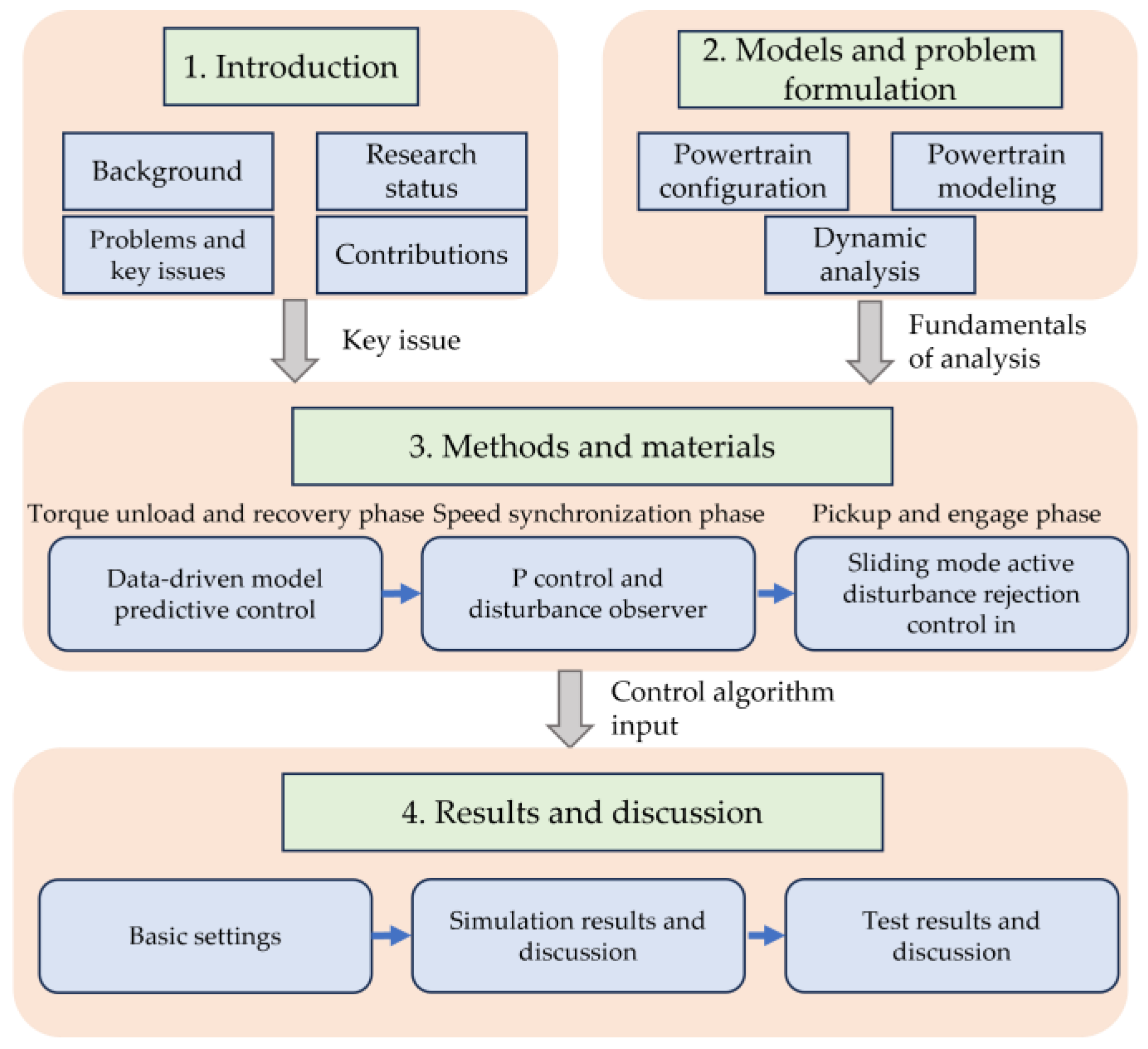
Figure 1. The design process studied in this paper.
Processes 11 02710 g001
Figure 2. Configuration of single-axis parallel hybrid electric powertrain.
Processes 11 02710 g002
Figure 3. Simplified driveline model.
Processes 11 02710 g003
Figure 4. AMT actuating mechanism.
Processes 11 02710 g004
Figure 5. Schematic diagram of the shifting process.
Processes 11 02710 g005
Figure 6. Block diagram of the multi-stage robust shifting control.
Processes 11 02710 g006
Figure 7. Principle of data-driven model predictive control method.
Processes 11 02710 g007
Figure 8. Principle of P control and disturbance observer.
Processes 11 02710 g008
Figure 9. Principle of sliding mode active disturbance rejection control.
Processes 11 02710 g009
Figure 10. Co-simulation platform.
Processes 11 02710 g010
Figure 11. Test bench architecture for single-axis parallel hybrid electric vehicle.
Processes 11 02710 g011
Figure 12. Test bench layout for the single-axis parallel hybrid electric vehicle.
Processes 11 02710 g012
Figure 13. Control effects of different controllers: (a) results of no active control; (b) results of PID control; (c) results of IMSR control.
Processes 11 02710 g013
Figure 14. Shift transient responses in heavy load climbing cycle.
Processes 11 02710 g014
Figure 15. Shift transient responses in light load climbing cycle.
Processes 11 02710 g015
Figure 16. Simulation result of pickup (disturbance condition1): (a) angular displacement; (b) angular displacement error.
Processes 11 02710 g016
Figure 17. Simulation result of pickup (disturbance condition2): (a) angular displacement; (b) angular displacement error.
Processes 11 02710 g017
Figure 18. IMSR control test results under acceleration and deceleration conditions: (a) velocity, input speed and gear; (b) torque and jerk.
Processes 11 02710 g018
Table 1. Phase division of the shifting process.
ItemDefinitionDescriptions
Phase1Torque unloadClear the torque of the EM
Phase2PickupControl the voltage of shifting motor to adjust the shifting force, and separate the sleeve and gear ring in the meshing state
Phase3Speed
synchronization
Motor controller controls the EM for speed regulation
Phase4EngageThe shift actuator pushes the sleeve to move axially and enter the target gear position
Phase5Torque recoveryRestore power according to the shift control strategy until the vehicle returns to normal driving mode
Table 2. Parameters of the simulation model.
ParameterValueParameterValue
J e 1.52 kg m2 A f 6.5 m2
J E M 0.047 kg m2 ρ 1.2258 kg/m3
R 1 0.071 m R w 0.528 m
R 2 0.035 m i f d 2.87
z 6 R m 0.33 Ω
μ k 0.095 L m 0.022 H
J A M T 0.37 kg m2 K e m f 0.04 Vs/rad
m 25,000 kg K m 0.02 Nm/A
g 9.8 m/s2 J m 0.002 kg m2
f 0.004 b m 0.0054 Nm/rad
C D 0.5 h 0.005 m
Table 3. Shift time and jerk comparison.
ItemNo Active ControlPID ControlIMSR Control
t 0 t 1 (ms)1207060
t 1 t 2 (ms)10010060
t 2 t 3 (ms)1406050
t 3 t 4 (ms)370330170
Total shift time (ms)730560340
Maximum jerk (m/s3)−19.83−15.36−7.58
Table 4. Statistical indicator results of no active control.
ItemGear1 to 2Gear2 to 3Gear3 to 4Gear4 to 5Gear5 to 6Gear6 to 7Gear7 to 8
t 0 t 1 (ms)100115102120105115110
t 1 t 2 (ms)107115115112106115112
t 2 t 3 (ms)155160137165178165158
t 3 t 4 (ms)342352335350330342335
Total shift time (ms)704742689747719737715
Maximum jerk (m/s3)17.508.4819.8215.3511.5614.2716.62
Friction work (J)9453.209885.368999.768750.969940.748867.329263.12
Table 5. Statistical indicator results of PID control.
ItemGear1 to 2Gear2 to 3Gear3 to 4Gear4 to 5Gear5 to 6Gear6 to 7Gear7 to 8
t 0 t 1 (ms)102115100112102115102
t 1 t 2 (ms)65626060586070
t 2 t 3 (ms)46515050485256
t 3 t 4 (ms)340338329353320365330
Total shift time (ms)553566539575528592558
Maximum jerk (m/s3)11.3611.5513.5010.6015.389.859.58
Friction work (J)9352.589016.188540.139469.588562.679003.988563.28
Table 6. Statistical indicator results of IMSR control.
ItemGear1 to 2Gear2 to 3Gear3 to 4Gear4 to 5Gear5 to 6Gear6 to 7Gear7 to 8
t 0 t 1 (ms)110100108100120120107
t 1 t 2 (ms)82656066686267
t 2 t 3 (ms)50525546525150
t 3 t 4 (ms)227205215237205220220
Total shift time (ms)469422438449445453444
Maximum jerk (m/s3)6.657.787.608.096.887.816.78
Friction work (J)434.88300.96243.36207.32399.16305.46320.18
Disclaimer/Publisher’s Note: The statements, opinions and data contained in all publications are solely those of the individual author(s) and contributor(s) and not of MDPI and/or the editor(s). MDPI and/or the editor(s) disclaim responsibility for any injury to people or property resulting from any ideas, methods, instructions or products referred to in the content.