
Catalytic Hydrogenation of Nitrate over Immobilized Nanocatalysts in a Multi-Phase Continuous Reaction System: System Performance, Characterization and Optimization


 ,
,  and
and 
Abstract
:
1. Introduction
2. Materials and Methods
2.1. Bimetallic Macrostructured Catalyst Preparation
2.2. Experimental Set-Up and Procedure
3. Results and Discussion
3.1. Bimetallic Macrostructured Catalyst Characterization
3.2. Continuous Catalytic Experiments Results
3.2.1. Parameter Optimization Experiments
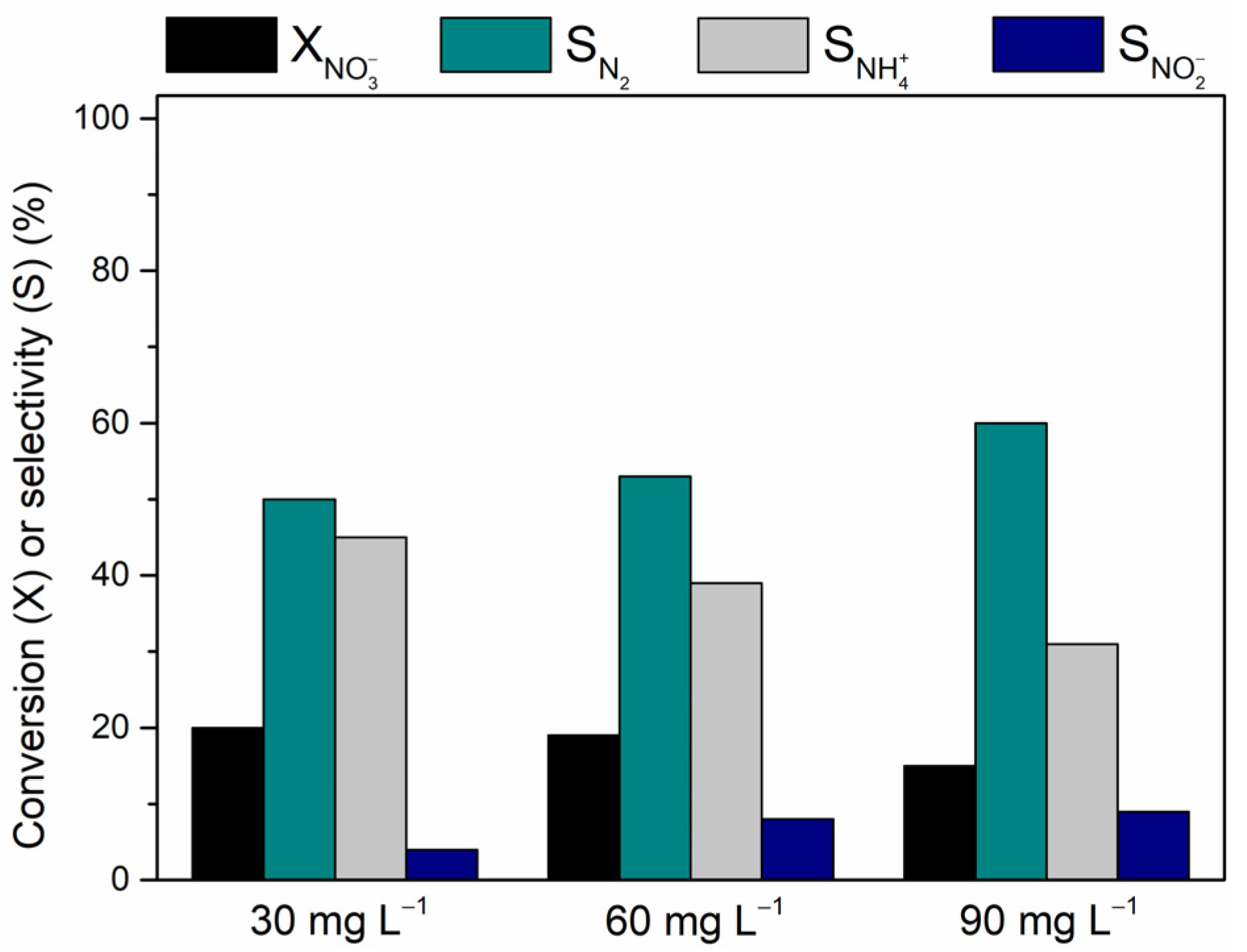
Inlet NO3− Concentration
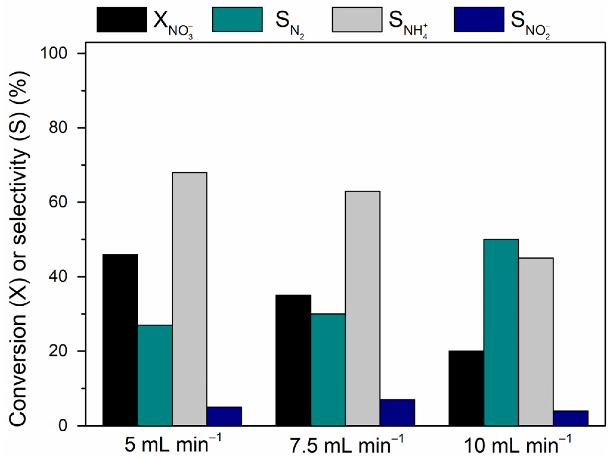
Liquid Flow Rates Optimization
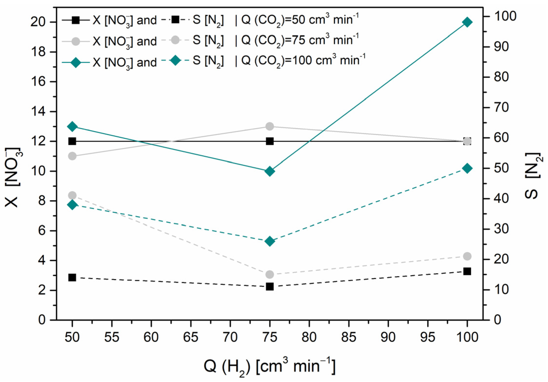
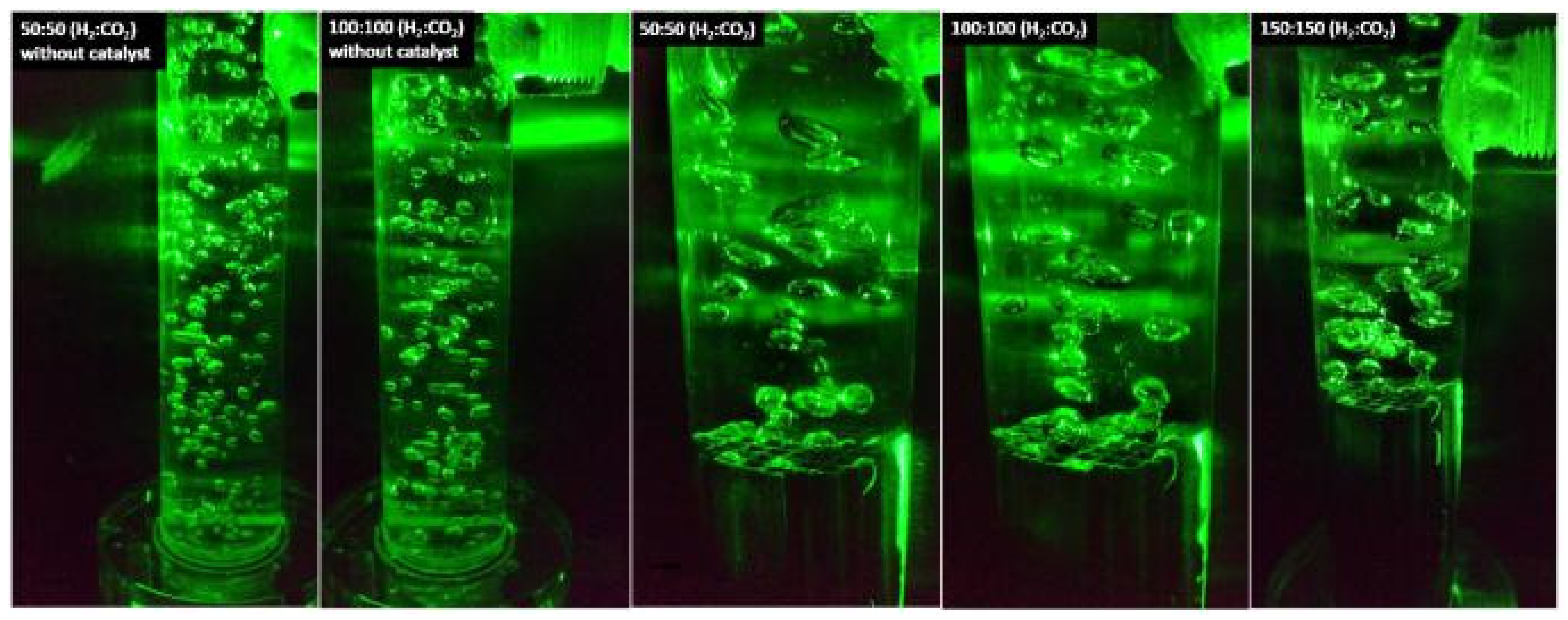
Gas Flow Rates Optimization
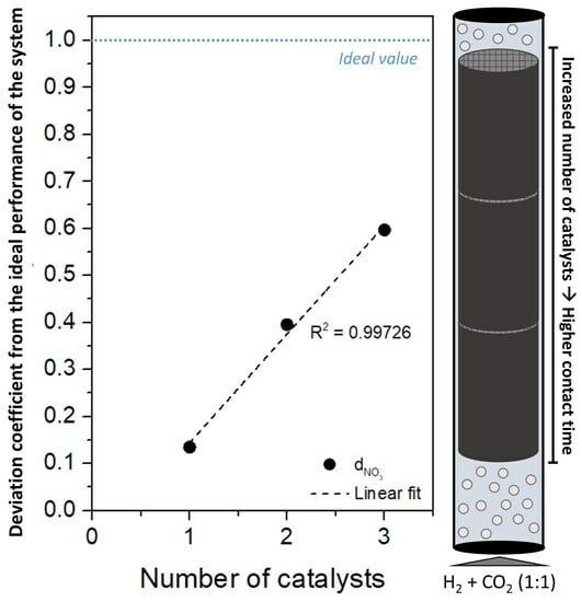
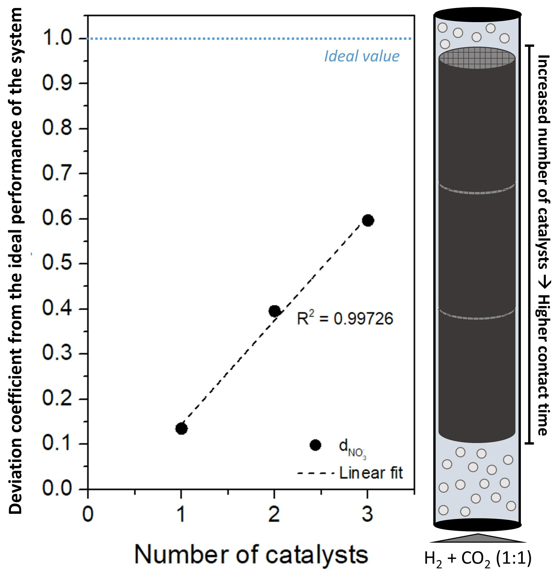
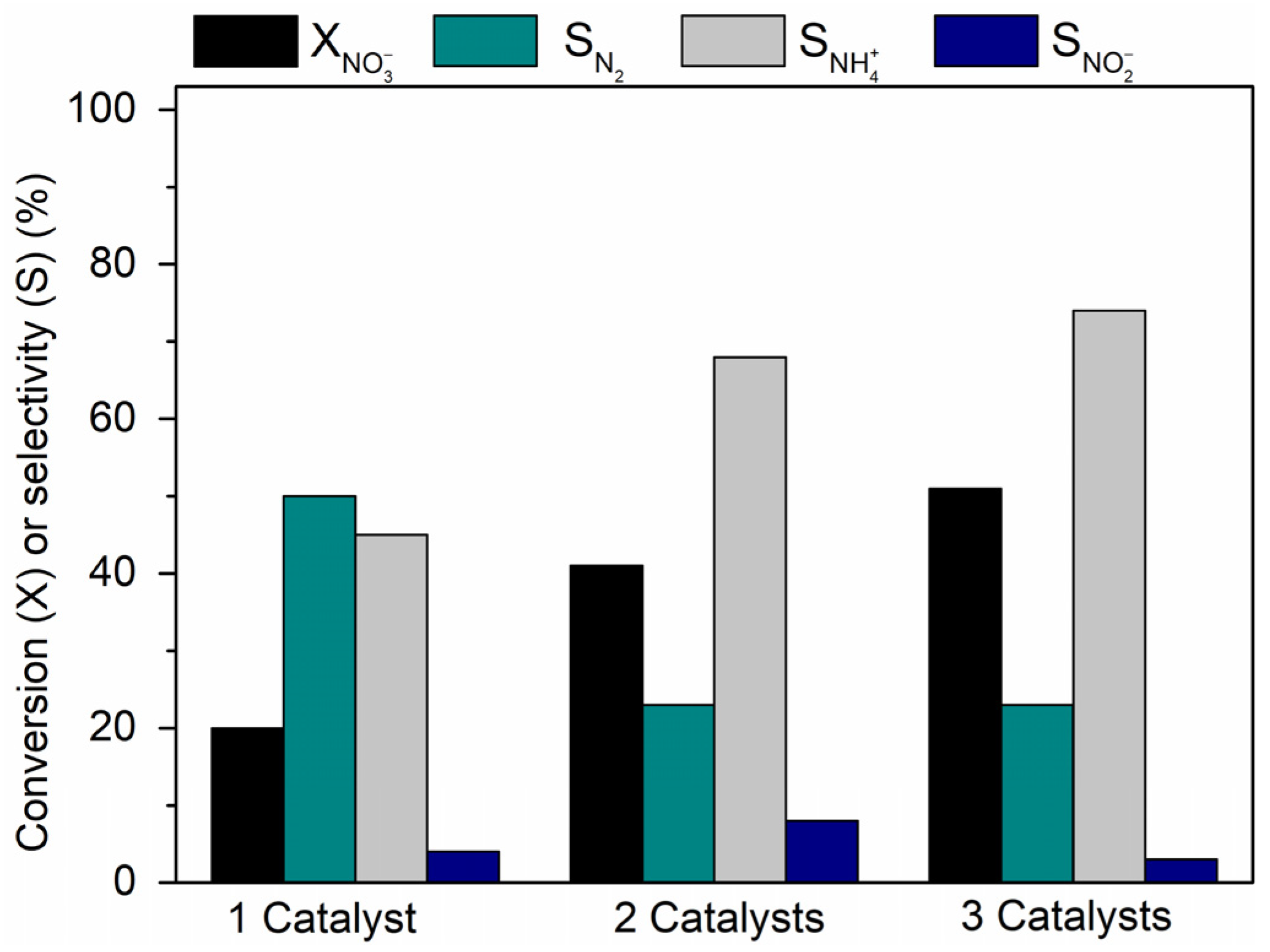
Influence of the Catalyst Amount
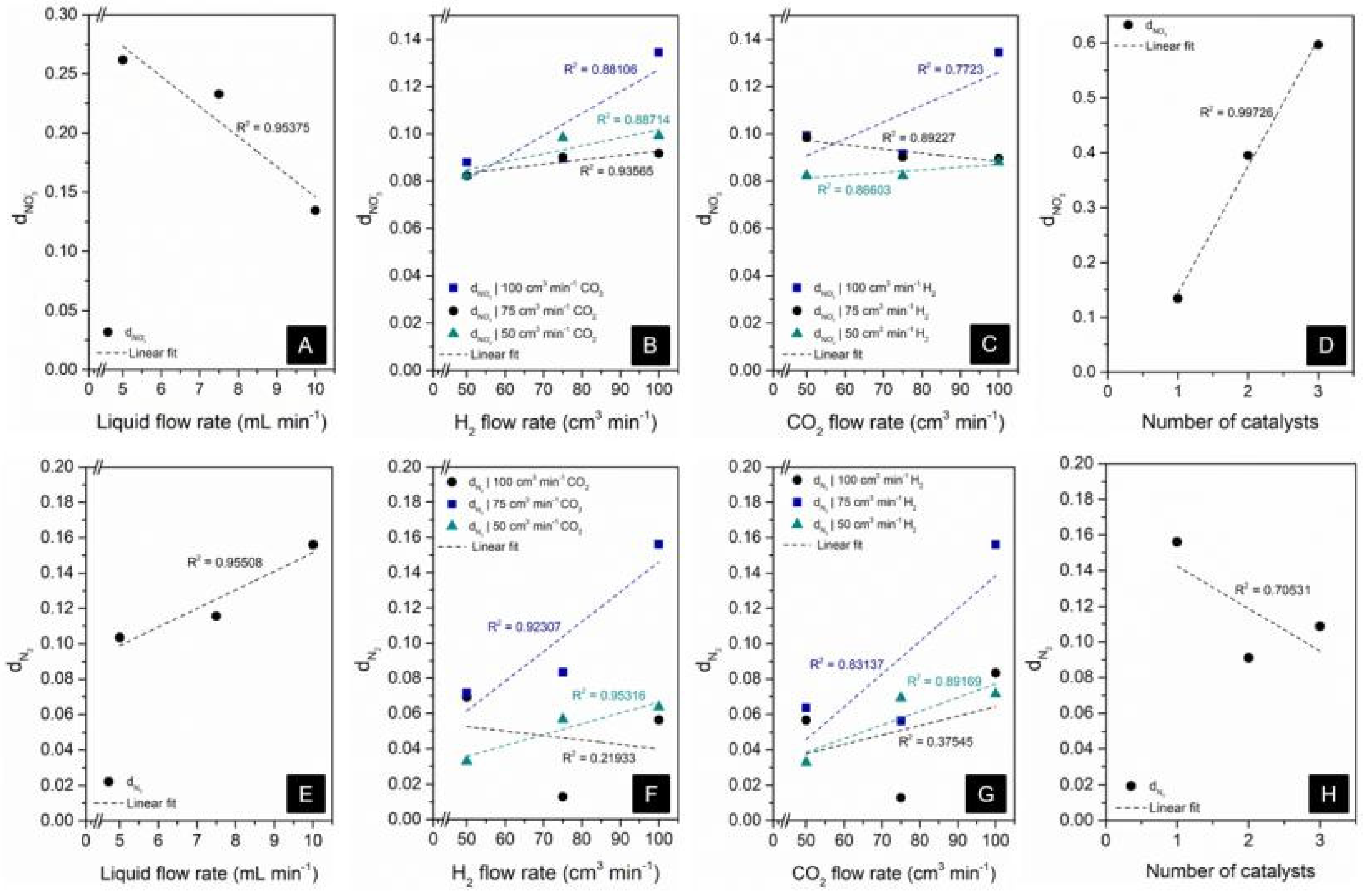
3.3. Assessment of Factors Affecting NO3− Conversion and N2 Formation
3.4. Final Remarks
4. Conclusions
Supplementary Materials
Author Contributions
Funding
Data Availability Statement
Conflicts of Interest
References
- Prüsse, U.; Hähnlein, M.; Daum, J.; Vorlop, K.-D. Improving the catalytic nitrate reduction. Catal. Today 2000, 55, 79–90. [Google Scholar] [CrossRef]
- Gatseva, P.D.; Argirova, M.D. High-nitrate levels in drinking water may be a risk factor for thyroid dysfunction in children and pregnant women living in rural Bulgarian areas. Int. J. Hyg. Environ. Health 2008, 211, 555–559. [Google Scholar] [CrossRef]
- Fraser, P.; Chilvers, C. Health aspects of nitrate in drinking water. Sci. Total Environ. 1981, 18, 103–116. [Google Scholar] [CrossRef] [PubMed]
- Winton, E.F.; Tardiff, R.G.; McCabe, L.J. Nitrate in drinking water. J.-Am. Water Work. Assoc. 1971, 63, 95–98. [Google Scholar] [CrossRef]
- Menció, A.; Mas-Pla, J.; Otero, N.; Regàs, O.; Boy-Roura, M.; Puig, R.; Bach, J.; Domènech, C.; Zamorano, M.; Brusi, D. Nitrate pollution of groundwater all right…, but nothing else? Sci. Total Environ. 2016, 539, 241–251. [Google Scholar] [CrossRef]
- Yang, C.; Cheng, M.; Tsai, S.; Hsieh, Y. Calcium, magnesium, and nitrate in drinking water and gastric cancer mortality. Jpn. J. Cancer Res. 1998, 89, 124–130. [Google Scholar] [CrossRef]
- Barrabés, N.; Sá, J. Catalytic nitrate removal from water, past, present and future perspectives. Appl. Catal. B Environ. 2011, 104, 1–5. [Google Scholar] [CrossRef]
- Zhou, M.; Wang, W.; Chi, M. Enhancement on the simultaneous removal of nitrate and organic pollutants from groundwater by a three-dimensional bio-electrochemical reactor. Bioresour. Technol. 2009, 100, 4662–4668. [Google Scholar] [CrossRef]
- Moussavi, G.; Shekoohiyan, S. Simultaneous nitrate reduction and acetaminophen oxidation using the continuous-flow chemical-less VUV process as an integrated advanced oxidation and reduction process. J. Hazard. Mater. 2016, 318, 329–338. [Google Scholar] [CrossRef]
- Pintar, A.; Batista, J.; Levec, J. Catalytic denitrification: Direct and indirect removal of nitrates from potable water. Catal. Today 2001, 66, 503–510. [Google Scholar] [CrossRef]
- Yang, T.; Doudrick, K.; Westerhoff, P. Photocatalytic reduction of nitrate using titanium dioxide for regeneration of ion exchange brine. Water Res. 2013, 47, 1299–1307. [Google Scholar] [CrossRef] [PubMed]
- Anoop, K.; Viraraghavan, T. Nitrate Removal From Drinking Water—Review. J. Environ. Eng. 1997, 123, 371–380. [Google Scholar] [CrossRef]
- Jensen, V.B.; Darby, J.L.; Seidel, C.; Gorman, C.; Jensen, V.B.; Darby, J.L.; Seidel, C.; Gorman, C.; Gorman, C. Nitrate in Potable Water Supplies: Alternative Management Strategies. Crit. Rev. Environ. Sci. Technol. 2014, 44, 2203–2286. [Google Scholar] [CrossRef]
- Mendow, G.; Veizaga, N.S.; Querini, C.A.; Sánchez, B.S. A continuous process for the catalytic reduction of water nitrate. J. Environ. Chem. Eng. 2019, 7, 102808. [Google Scholar] [CrossRef]
- Prüsse, U.; Vorlop, K.-D. Supported bimetallic palladium catalysts for water-phase nitrate reduction. J. Mol. Catal. A Chem. 2001, 173, 313–328. [Google Scholar] [CrossRef]
- Gauthard, F.; Epron, F.; Barbier, J. Palladium and platinum-based catalysts in the catalytic reduction of nitrate in water: Effect of copper, silver, or gold addition. J. Catal. 2003, 220, 182–191. [Google Scholar] [CrossRef]
- Mendow, G.; Marchesini, F.A.; Miro, E.E.; Querini, C.A. Evaluation of Pd- In supported catalysts for water nitrate abatement in a fixed-bed continuous reactor. Ind. Eng. Chem. Res. 2011, 50, 1911–1920. [Google Scholar] [CrossRef]
- Epron, F.; Gauthard, F.; Pinéda, C.; Barbier, J. Catalytic reduction of nitrate and nitrite on Pt–Cu/Al2O3 catalysts in aqueous solution: Role of the interaction between copper and platinum in the reaction. J. Catal. 2001, 198, 309–318. [Google Scholar] [CrossRef]
- Hörold, S.; Vorlop, K.-D.; Tacke, T.; Sell, M. Development of catalysts for a selective nitrate and nitrite removal from drinking water. Catal. Today 1993, 17, 21–30. [Google Scholar] [CrossRef]
- Lubphoo, Y.; Chyan, J.-M.; Grisdanurak, N.; Liao, C.-H. Nitrogen gas selectivity enhancement on nitrate denitrification using nanoscale zero-valent iron supported palladium/copper catalysts. J. Taiwan Inst. Chem. Eng. 2015, 57, 143–153. [Google Scholar] [CrossRef]
- Pintar, A.; Batista, J.; Muševič, I. Palladium-copper and palladium-tin catalysts in the liquid phase nitrate hydrogenation in a batch-recycle reactor. Appl. Catal. B Environ. 2004, 52, 49–60. [Google Scholar] [CrossRef]
- Santos, A.; Restivo, J.; Orge, C.A.; Pereira, M.F.R.; Soares, O. Nitrate Catalytic Reduction over Bimetallic Catalysts: Catalyst Optimization. C 2020, 6, 78. [Google Scholar] [CrossRef]
- Soares, O.S.G.P.; Órfão, J.J.M.; Pereira, M.F.R. Nitrate Reduction Catalyzed by Pd–Cu and Pt–Cu Supported on Different Carbon Materials. Catal. Lett. 2010, 139, 97–104. [Google Scholar] [CrossRef]
- Sá, J.; Gross, S.; Vinek, H. Effect of the reducing step on the properties of Pd-Cu bimetallic catalysts used for denitration. Appl. Catal. A Gen. 2005, 294, 226–234. [Google Scholar] [CrossRef]
- Tokazhanov, G.; Ramazanova, E.; Hamid, S.; Bae, S.; Lee, W. Advances in the catalytic reduction of nitrate by metallic catalysts for high efficiency and N2 selectivity: A review. Chem. Eng. J. 2020, 384, 123252. [Google Scholar] [CrossRef]
- Hu, M.; Liu, Y.; Yao, Z.; Ma, L.; Wang, X. Catalytic reduction for water treatment. Front. Environ. Sci. Eng. 2017, 12, 3. [Google Scholar] [CrossRef]
- Chen, Y.-X.; Zhang, Y.; Chen, G.-H. Appropriate conditions or maximizing catalytic reduction efficiency of nitrate into nitrogen gas in groundwater. Water Res. 2003, 37, 2489–2495. [Google Scholar] [CrossRef]
- Barrabés, N.; Just, J.; Dafinov, A.; Medina, F.; Fierro, J.L.G.; Sueiras, J.E.; Salagre, P.; Cesteros, Y. Catalytic reduction of nitrate on Pt-Cu and Pd-Cu on active carbon using continuous reactor: The effect of copper nanoparticles. Appl. Catal. B Environ. 2006, 62, 77–85. [Google Scholar] [CrossRef]
- Shukla, A.; Pande, J.V.; Bansiwal, A.; Osiceanu, P.; Biniwale, R.B. Catalytic Hydrogenation of Aqueous Phase Nitrate Over Fe/C Catalysts. Catal. Lett. 2009, 131, 451–457. [Google Scholar] [CrossRef]
- Marchesini, F.A.; Mendow, G.; Picard, N.P.; Zoppas, F.M.; Aghemo, V.S.; Gutierrez, L.B.; Querini, C.A.; Miro, E.E. PdIn catalysts in a continuous fixed bed reactor for the nitrate removal from groundwater. Int. J. Chem. React. Eng. 2019, 17, 20180126. [Google Scholar] [CrossRef]
- Barrabés, N.; Dafinov, A.; Medina, F.; Sueiras, J.E. Catalytic reduction of nitrates using Pt/CeO2 catalysts in a continuous reactor. Catal. Today 2010, 149, 341–347. [Google Scholar] [CrossRef]
- Aristizábal, A.; Contreras, S.; Barrabés, N.; Llorca, J.; Tichit, D.; Medina, F. Catalytic reduction of nitrates in water on Pt promoted Cu hydrotalcite-derived catalysts: Effect of the Pt–Cu alloy formation. Appl. Catal. B Environ. 2011, 110, 58–70. [Google Scholar] [CrossRef]
- Pintar, A.; Batista, J. Catalytic hydrogenation of aqueous nitrate solutions in fixed-bed reactors. Catal. Today 1999, 53, 35–50. [Google Scholar] [CrossRef]
- Yuranova, T.; Kiwi-Minsker, L.; Franch, C.; Palomares, A.E.; Armenise, S.; García-Bordejé, E. Nanostructured catalysts for the continuous reduction of nitrates and bromates in water. Ind. Eng. Chem. Res. 2013, 52, 13930–13937. [Google Scholar] [CrossRef]
- Restivo, J.; Soares, O.; Orfao, J.J.M.; Pereira, M.F.R. Catalytic reduction of bromate over monometallic catalysts on different powder and structured supports. Chem. Eng. J. 2017, 309, 197–205. [Google Scholar] [CrossRef]
- Wa, J.; Turunen, I.; Salmi, T.; Maunula, T. Kinetics of nitrate reduction in monolith reactor. Chem. Eng. Sci. 1994, 49, 5763–5773. [Google Scholar] [CrossRef]
- Peroni, B.; Navas, M.; Bideberripe, H.P.; Barbero, B.; Casella, M.L.; Jaworski, M.A. Development of PdCu Structured Catalysts Based on ZrO2–CeO2 Materials Supported on Cordierite Monoliths for Water Remediation: Removal of Hazardous Oxyanions. Ind. Eng. Chem. Res. 2021, 60, 12767–12775. [Google Scholar] [CrossRef]
- Hosseini, S.; Moghaddas, H.; Masoudi Soltani, S.; Kheawhom, S. Technological Applications of Honeycomb Monoliths in Environmental Processes: A review. Process Saf. Environ. Prot. 2020, 133, 286–300. [Google Scholar] [CrossRef]
- Ren, Z.; Guo, Y.; Gao, P.-X. Nano-array based monolithic catalysts: Concept, rational materials design and tunable catalytic performance. Catal. Today 2015, 258, 441–453. [Google Scholar] [CrossRef]
- Tomašić, V.; Jović, F. State-of-the-art in the monolithic catalysts/reactors. Appl. Catal. A Gen. 2006, 311, 112–121. [Google Scholar] [CrossRef]
- Cybulski, A.; Moulijn, J.A. Monoliths in Heterogeneous Catalysis. Catal. Rev. 1994, 36, 179–270. [Google Scholar] [CrossRef]
- Santos, A.S.G.G.; Restivo, J.; Orge, C.A.; Pereira, M.F.R.; Soares, O.S.G.P. Design of macrostructured bimetallic MWCNT catalysts for multi-phasic hydrogenation in water treatment with pre- and post-coating metal phase impregnation. Appl. Catal. A Gen. 2022, 643, 118790. [Google Scholar] [CrossRef]
- Restivo, J.; Orge, C.A.; Guedes Gorito dos Santos, A.S.; Gonçalves Pinto Soares, O.S.; Ribeiro Pereira, M.F. Influence of preparation methods on the activity of macro-structured ball-milled MWCNT catalysts in the ozonation of organic pollutants. J. Environ. Chem. Eng. 2020, 104578. [Google Scholar] [CrossRef]
- Rojas, J.A.; Ardila-Rodríguez, L.A.; Diniz, M.F.; Gonçalves, M.; Ribeiro, B.; Rezende, M.C. Optimization of Triton X-100 removal and ultrasound probe parameters in the preparation of multiwalled carbon nanotube buckypaper. Mater. Des. 2019, 166, 107612. [Google Scholar] [CrossRef]
- Santos, A.; Restivo, J.; Orge, C.A.; Pereira, M.F.R.; Soares, O. Synthesis of monometallic macrostructured catalysts for bromate reduction in a continuous catalytic system. Environ. Technol. 2022. [Google Scholar] [CrossRef]
- Nauman, E.B. Residence Time Distributions; Wiley: Hoboken, NJ, USA, 2003. [Google Scholar]
- Soares, O.S.G.; Fan, X.; Orfao, J.J.; Lapkin, A.A.; Pereira, M.F.R. Kinetic Modeling of Nitrate Reduction Catalyzed by Pd-Cu Supported on Carbon Nanotubes. Ind. Eng. Chem. Res. 2012, 51, 4854–4860. [Google Scholar] [CrossRef]
- Panić, S.; Kukovecz, Á.; Boskovic, G. Design of catalytic carbon nanotube-based reactor for water denitration—The impact of active metal confinement. Appl. Catal. B Environ. 2018, 225, 207–217. [Google Scholar] [CrossRef]
- Soares, O.S.G.P.; Gonçalves, A.G.; Delgado, J.J.; Órfão, J.J.M.; Pereira, M.F.R. Modification of carbon nanotubes by ball-milling to be used as ozonation catalysts. Catal. Today 2015, 249, 199–203. [Google Scholar] [CrossRef]
- Hamid, S.; Lee, W. Nitrate reduction by iron supported bimetallic catalyst in low and high nitrogen regimes. Adv. Environ. Res. 2015, 4, 263–271. [Google Scholar] [CrossRef]
- Huang, C.-P.; Wang, H.-W.; Chiu, P.-C. Nitrate reduction by metallic iron. Water Res. 1998, 32, 2257–2264. [Google Scholar] [CrossRef]
- Liu, H.; Guo, M.; Zhang, Y. Nitrate removal by Fe0/Pd/Cu nano-composite in groundwater. Environ. Technol. 2014, 35, 917–924. [Google Scholar] [CrossRef]
- Zhang, Y.; Douglas, G.B.; Pu, L.; Zhao, Q.; Tang, Y.; Xu, W.; Luo, B.; Hong, W.; Cui, L.; Ye, Z. Zero-valent iron-facilitated reduction of nitrate: Chemical kinetics and reaction pathways. Sci. Total Environ. 2017, 598, 1140–1150. [Google Scholar] [CrossRef] [PubMed]
- Hamid, S.; Bae, S.; Lee, W.; Amin, M.T.; Alazba, A.A. Catalytic nitrate removal in continuous bimetallic Cu–Pd/nanoscale zerovalent iron system. Ind. Eng. Chem. Res. 2015, 54, 6247–6257. [Google Scholar] [CrossRef]
- Vorlop, K.-D.; Tacke, T. Erste schritte auf dem weg zur edelmetallkatalysierten nitrat-und nitrit-entfernung aus trinkwasser. Chemieingenieurtechnik 1989, 61, 836–837. [Google Scholar] [CrossRef]
- Hamid, S.; Bae, S.; Lee, W. Novel bimetallic catalyst supported by red mud for enhanced nitrate reduction. Chem. Eng. J. 2018, 348, 877–887. [Google Scholar] [CrossRef]
- Strukul, G.; Gavagnin, R.; Pinna, F.; Modaferri, E.; Perathoner, S.; Centi, G.; Marella, M.; Tomaselli, M. Use of palladium based catalysts in the hydrogenation of nitrates in drinking water: From powders to membranes. Catal. Today 2000, 55, 139–149. [Google Scholar] [CrossRef]
- Jung, J.; Bae, S.; Lee, W. Nitrate reduction by maghemite supported Cu-Pd bimetallic catalyst. Appl. Catal. B Environ. 2012, 127, 148–158. [Google Scholar] [CrossRef]
- Zhao, W.; Zhu, X.; Wang, Y.; Ai, Z.; Zhao, D. Catalytic reduction of aqueous nitrates by metal supported catalysts on Al particles. Chem. Eng. J. 2014, 254, 410–417. [Google Scholar] [CrossRef]
- D’Arino, M.; Pinna, F.; Strukul, G. Nitrate and nitrite hydrogenation with Pd and Pt/SnO2 catalysts: The effect of the support porosity and the role of carbon dioxide in the control of selectivity. Appl. Catal. B Environ. 2004, 53, 161–168. [Google Scholar] [CrossRef]
- Nijhuis, T.A.; Kreutzer, M.T.; Romijn, A.C.J.; Kapteijn, F.; Moulijn, J.A. Monolithic catalysts as more efficient three-phase reactors. Catal. Today 2001, 66, 157–165. [Google Scholar] [CrossRef]
- Roy, S.; Bauer, T.; Al-Dahhan, M.; Lehner, P.; Turek, T. Monoliths as multiphase reactors: A review. AIChE J. 2004, 50, 2918–2938. [Google Scholar] [CrossRef]
- Roy, S.; Al-Dahhan, M. Flow distribution characteristics of a gas–liquid monolith reactor. Catal. Today 2005, 105, 396–400. [Google Scholar] [CrossRef]
- Heiszwolf, J.J.; Kreutzer, M.T.; van den Eijnden, M.G.; Kapteijn, F.; Moulijn, J.A. Gas–liquid mass transfer of aqueous Taylor flow in monoliths. Catal. Today 2001, 69, 51–55. [Google Scholar] [CrossRef]
- Ito, D.; Damsohn, M.; Prasser, H.-M.; Aritomi, M. Dynamic film thickness between bubbles and wall in a narrow channel. Exp. Fluids 2011, 51, 821–833. [Google Scholar] [CrossRef]
- Tsoligkas, A.N.; Simmons, M.J.H.; Wood, J.; Frost, C.G. Kinetic and selectivity studies of gas–liquid reaction under Taylor flow in a circular capillary. Catal. Today 2007, 128, 36–46. [Google Scholar] [CrossRef]
- Bercic, G.; Pintar, A. The role of gas bubbles and liquid slug lengths on mass transport in the Taylor flow through capillaries. Chem. Eng. Sci. 1997, 52, 3709–3719. [Google Scholar] [CrossRef]
- Vandu, C.O.; Ellenberger, J.; Krishna, R. Hydrodynamics and mass transfer in an upflow monolith loop reactor. Chem. Eng. Process. Process Intensif. 2005, 44, 363–374. [Google Scholar] [CrossRef]
- Kreutzer, M.T.; Du, P.; Heiszwolf, J.J.; Kapteijn, F.; Moulijn, J.A. Mass transfer characteristics of three-phase monolith reactors. Chem. Eng. Sci. 2001, 56, 6015–6023. [Google Scholar] [CrossRef]


Disclaimer/Publisher’s Note: The statements, opinions and data contained in all publications are solely those of the individual author(s) and contributor(s) and not of MDPI and/or the editor(s). MDPI and/or the editor(s) disclaim responsibility for any injury to people or property resulting from any ideas, methods, instructions or products referred to in the content. |
© 2023 by the authors. Licensee MDPI, Basel, Switzerland. This article is an open access article distributed under the terms and conditions of the Creative Commons Attribution (CC BY) license (https://creativecommons.org/licenses/by/4.0/).
Share and Cite
Santos, A.S.G.G.; Restivo, J.; Orge, C.A.; Pereira, M.F.R.; Soares, O.S.G.P. Catalytic Hydrogenation of Nitrate over Immobilized Nanocatalysts in a Multi-Phase Continuous Reaction System: System Performance, Characterization and Optimization. Processes 2023, 11, 2692. https://doi.org/10.3390/pr11092692
Santos ASGG, Restivo J, Orge CA, Pereira MFR, Soares OSGP. Catalytic Hydrogenation of Nitrate over Immobilized Nanocatalysts in a Multi-Phase Continuous Reaction System: System Performance, Characterization and Optimization. Processes. 2023; 11(9):2692. https://doi.org/10.3390/pr11092692
Chicago/Turabian StyleSantos, Ana Sofia G. G., João Restivo, Carla Alexandra Orge, Manuel Fernando R. Pereira, and Olívia Salomé G. P. Soares. 2023. "Catalytic Hydrogenation of Nitrate over Immobilized Nanocatalysts in a Multi-Phase Continuous Reaction System: System Performance, Characterization and Optimization" Processes 11, no. 9: 2692. https://doi.org/10.3390/pr11092692
APA StyleSantos, A. S. G. G., Restivo, J., Orge, C. A., Pereira, M. F. R., & Soares, O. S. G. P. (2023). Catalytic Hydrogenation of Nitrate over Immobilized Nanocatalysts in a Multi-Phase Continuous Reaction System: System Performance, Characterization and Optimization. Processes, 11(9), 2692. https://doi.org/10.3390/pr11092692