
Cu2O-Electrodeposited TiO2 Photoelectrode for Integrated Solar Redox Flow Battery


Abstract
:1. Introduction
2. Materials and Methods
2.1. Chemicals
2.2. Preparation of TiO2 Sol
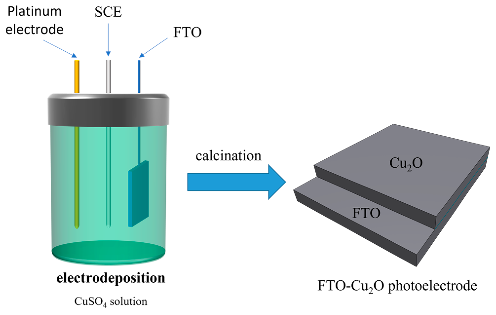
2.3. Preparation of Electrodes
2.4. Preparation of Electrolyte
2.5. Photoelectrochemical Characterisation
3. Results
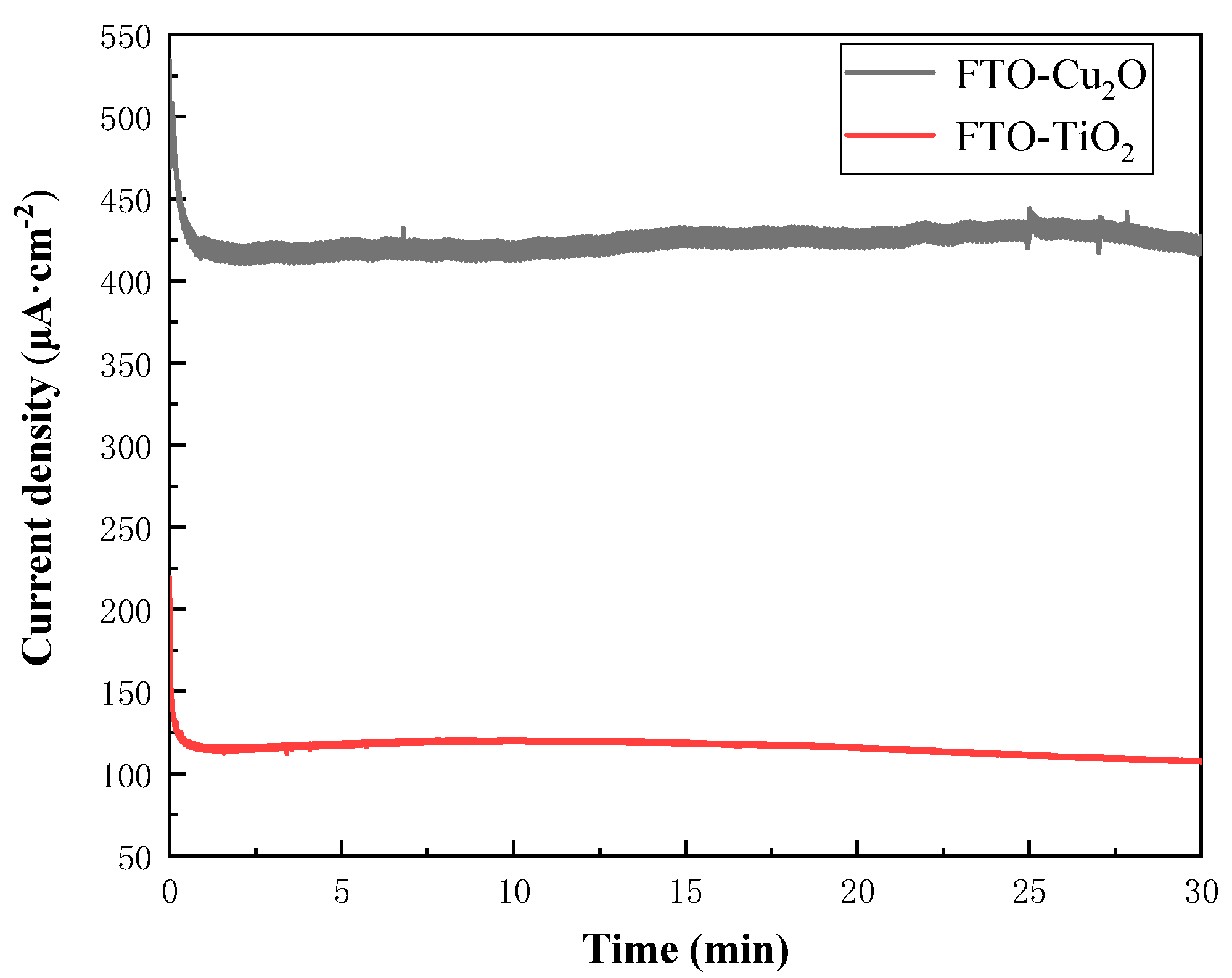
3.1. Half-Cell Testing
3.2. Full-Cell Testing
3.3. XRD Analysis
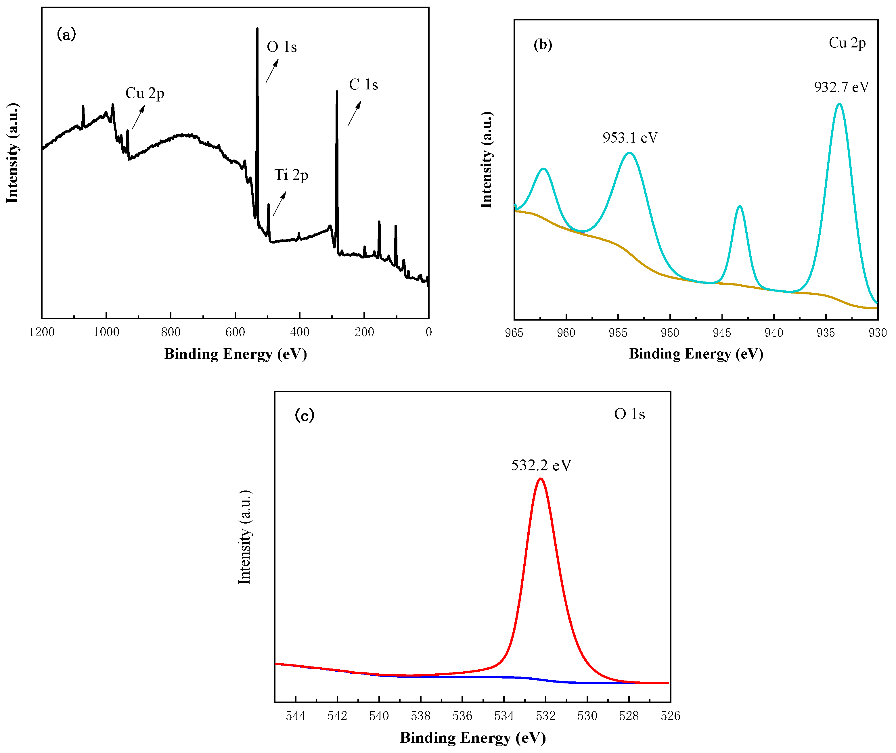
3.4. XPS Analysis
3.5. UV-Vis Analysis
4. Conclusions
Author Contributions
Funding
Data Availability Statement
Acknowledgments
Conflicts of Interest
References
- Cui, H.; Zhao, W.; Yang, C.; Yin, H.; Lin, T.; Shan, Y.; Xie, Y.; Gu, H.; Huang, F. Black TiO2 nanotube arrays for high-efficiency photoelectrochemical water-splitting. J. Mater. Chem. A 2014, 2, 8612–8616. [Google Scholar] [CrossRef]
- Fujishima, A.; Rao, T.N.; Tryk, D.A. Titanium dioxide photocatalysis. J. Photochem. Photobiol. C Photochem. Rev. 2000, 1, 1–21. [Google Scholar] [CrossRef]
- Ohno, T.; Mitsui, T.; Matsumura, M. Photocatalytic Activity of S-doped TiO2 Photocatalyst under Visible Light. Chem. Lett. 2003, 32, 364–365. [Google Scholar] [CrossRef]
- Akpan, U.G.; Hameed, B.H. The advancements in sol–gel method of doped-TiO2 photocatalysts. Appl. Catal. A Gen. 2010, 375, 1–11. [Google Scholar] [CrossRef]
- Nakata, K.; Fujishima, A. TiO2 photocatalysis: Design and applications. J. Photochem. Photobiol. C Photochem. Rev. 2012, 13, 169–189. [Google Scholar] [CrossRef]
- Fujishima, A.; Honda, K. Electrochemical Photolysis of Water at a Semiconductor Electrode. Nature 1972, 238, 37–38. [Google Scholar] [CrossRef]
- Butburee, T.; Bai, Y.; Wang, H.; Chen, H.; Wang, Z.; Liu, G.; Zou, J.; Khemthong, P.; Lu, G.Q.M.; Wang, L. 2D Porous TiO2 Single-Crystalline Nanostructure Demonstrating High Photo-Electrochemical Water Splitting Performance. Adv. Mater. 2018, 30, 1705666. [Google Scholar] [CrossRef]
- Whitley, S.; Bae, D. Perspective-Insights into Solar-Rechargeable Redox Flow Cell Design: A Practical Perspective for Lab-Scale Experiments. J. Electrochem. Soc. 2021, 168, 120517. [Google Scholar] [CrossRef]
- Cao, L.Y.; Skyllas-Kazacos, M.; Wang, D.W. Solar Redox Flow Batteries: Mechanism, Design, and Measurement. Adv. Sustain. Syst. 2018, 2, 1800031. [Google Scholar] [CrossRef]
- Li, W.J.; Jin, S. Design Principles and Developments of Integrated Solar Flow Batteries. Acc. Chem. Res. 2020, 53, 2611–2621. [Google Scholar] [CrossRef]
- Binetti, E.; El Koura, Z.; Bazzanella, N.; Carotenuto, G.; Miotello, A. Synthesis of mesoporous ITO/TiO2 electrodes for optoelectronics. Mater. Lett. 2015, 139, 355–358. [Google Scholar] [CrossRef]
- Sivula, K.; van de Krol, R. Semiconducting materials for photoelectrochemical energy conversion. Nat. Rev. Mater. 2016, 1, 15010. [Google Scholar] [CrossRef]
- Yang, W.; Moon, J. Recent Advances in Earth-Abundant Photocathodes for Photoelectrochemical Water Splitting. ChemSusChem 2019, 12, 1889–1899. [Google Scholar] [CrossRef]
- Yang, Y.; Niu, S.; Han, D.; Liu, T.; Wang, G.; Li, Y. Progress in Developing Metal Oxide Nanomaterials for Photoelectrochemical Water Splitting. Adv. Energy Mater. 2017, 7, 1700555. [Google Scholar] [CrossRef]
- Ciria-Ramos, I.; Juarez-Perez, E.J.; Haro, M. Solar Energy Storage Using a Cu2O-TiO2 Photocathode in a Lithium Battery. Small 2023, 19, 2301244. [Google Scholar] [CrossRef] [PubMed]
- Yin, T.-H.; Liu, B.-J.; Lin, Y.-W.; Li, Y.-S.; Lai, C.-W.; Lan, Y.-P.; Choi, C.; Chang, H.-C.; Choi, Y. Electrodeposition of Copper Oxides as Cost-Effective Heterojunction Photoelectrode Materials for Solar Water Splitting. Coatings 2022, 12, 1839. [Google Scholar] [CrossRef]
- El Koura, Z.; Cazzanelli, M.; Bazzanella, N.; Patel, N.; Fernandes, R.; Arnaoutakis, G.E.; Gakamsky, A.; Dick, A.; Quaranta, A.; Miotello, A. Synthesis and Characterization of Cu and N Codoped RF-Sputtered TiO2 Films: Photoluminescence Dynamics of Charge Carriers Relevant for Water Splitting. J. Phys. Chem. C 2016, 120, 12042–12050. [Google Scholar] [CrossRef]
- Tilley, S.D. Recent Advances and Emerging Trends in Photo-Electrochemical Solar Energy Conversion. Adv. Energy Mater. 2019, 9, 1802877. [Google Scholar] [CrossRef]
- Matamala-Troncoso, F.; Sáez-Navarrete, C.; Mejía-López, J.; García, G.; Rebolledo-Oyarce, J.; Nguyen, C.K.; MacFarlane, D.R.; Isaacs, M. Experimental and theoretical study of synthesis and properties of Cu2O/TiO2 heterojunction for photoelectrochemical purposes. Surf. Interfaces 2023, 37, 102751. [Google Scholar] [CrossRef]
- Huang, L.; Zhang, S.; Peng, F.; Wang, H.; Yu, H.; Yang, J.; Zhang, S.; Zhao, H. Electrodeposition preparation of octahedral-Cu2O-loaded TiO2 nanotube arrays for visible light-driven photocatalysis. Scr. Mater. 2010, 63, 159–161. [Google Scholar] [CrossRef]
- Marathey, P.; Patel, B.; Khanna, S.; Vanpariya, A.; Ray, A. Photoelectrochemical characteristics of electrodeposited cuprous oxide with protective over layers for hydrogen evolution reactions. Int. J. Hydrogen Energy 2021, 46, 16431–16439. [Google Scholar] [CrossRef]
- Rubino, A.; Zanoni, R.; Schiavi, P.G.; Latini, A.; Pagnanelli, F. Two-Dimensional Restructuring of Cu2O Can Improve the Performance of Nanosized n-TiO2/p-Cu2O Photoelectrodes under UV-Visible Light. Acs Appl. Mater. Interfaces 2021, 13, 47932–47944. [Google Scholar] [CrossRef] [PubMed]
- Asemi, M.; Maleki, S.; Ghanaatshoar, M. Cr-doped TiO2-based dye-sensitized solar cells with Cr-doped TiO2 blocking layer. J. Sol-Gel Sci. Technol. 2017, 81, 645–651. [Google Scholar] [CrossRef]
- Gayathri, V.; John Peter, I.; Rajamanickam, N.; Ramachandran, K. Improved performance of dye-sensitized solar cells by Cr doped TiO2 nanoparticles. Mater. Today Proc. 2021, 35, 23–26. [Google Scholar] [CrossRef]
- Kim, C.; Kim, K.S.; Kim, H.Y.; Han, Y.S. Modification of a TiO2 photoanode by using Cr-doped TiO2 with an influence on the photovoltaic efficiency of a dye-sensitized solar cell. J. Mater. Chem. 2008, 18, 5809–5814. [Google Scholar] [CrossRef]
- Nguyen, H.H.; Gyawali, G.; Hoon, J.S.; Sekino, T.; Lee, S.W. Cr-doped TiO2 nanotubes with a double-layer model: An effective way to improve the efficiency of dye-sensitized solar cells. Appl. Surf. Sci. 2018, 458, 523–528. [Google Scholar] [CrossRef]
- Xie, Y.; Huang, N.; You, S.; Liu, Y.; Sebo, B.; Liang, L.; Fang, X.; Liu, W.; Guo, S.; Zhao, X.-Z. Improved performance of dye-sensitized solar cells by trace amount Cr-doped TiO2 photoelectrodes. J. Power Sources 2013, 224, 168–173. [Google Scholar] [CrossRef]
- Chahid, S.; de los Santos, D.M.; Alcantara, R. The effect of Cu-doped TiO2 photoanode on photovoltaic performance of dye-sensitized solar cells. In Proceedings of the 3rd International Conference on Smart City Applications (SCA’), Tetouan, Morocco, 10–11 October 2018. [Google Scholar]
- Ünlü, B.; Özacar, M. Effect of Cu and Mn amounts doped to TiO2 on the performance of DSSCs. Sol. Energy 2020, 196, 448–456. [Google Scholar] [CrossRef]
- Dhonde, M.; Sahu, K.; Murty, V.V.S.; Nemala, S.S.; Bhargava, P. Surface plasmon resonance effect of Cu nanoparticles in a dye sensitized solar cell. Electrochim. Acta 2017, 249, 89–95. [Google Scholar] [CrossRef]
- Javed, H.M.A.; Sarfaraz, M.; Mustafa, M.S.; Que, W.X.; Ateeq ur, R.; Awais, M.; Hussain, S.; Qureshi, A.A.; Iqbal, M.Z.; Khan, M.A. Efficient Cu/rGO/TiO2 nanocomposite-based photoanode for highly-optimized plasmonic dye-sensitized solar cells. Appl. Nanosci. 2020, 10, 2419–2427. [Google Scholar] [CrossRef]
- Khan, M.I.; Rehman, M.A.; Saleem, M.; Baig, M.R.; Rehman, S.; Farooq, W.A.; Atif, M.; Hanif, A. Synthesis and characterization of nanostructured photoanodes for dye sensitized solar cells. Ceram. Int. 2019, 45, 20589–20592. [Google Scholar] [CrossRef]
- Park, J.-Y.; Kim, C.-S.; Okuyama, K.; Lee, H.-M.; Jang, H.-D.; Lee, S.-E.; Kim, T.-O. Copper and nitrogen doping on TiO2 photoelectrodes and their functions in dye-sensitized solar cells. J. Power Sources 2016, 306, 764–771. [Google Scholar] [CrossRef]
- Venumbaka, M.R.; Akkala, N.; Duraisamy, S.; Sigamani, S.; Poola, P.K.; D, S.R.; Marepally, B.C. Performance of TiO2, Cu-TiO2, and N-TiO2 nanoparticles sensitization with natural dyes for dye sensitized solar cells. Mater. Today Proc. 2022, 49, 2747–2751. [Google Scholar] [CrossRef]
- Zatirostami, A. A dramatic improvement in the efficiency of TiO2-based DSSCs by simultaneous incorporation of Cu and Se into its lattice. Opt. Mater. 2021, 117, 111110. [Google Scholar] [CrossRef]
- Hu, S.; Shaner, M.R.; Beardslee, J.A.; Lichterman, M.; Brunschwig, B.S.; Lewis, N.S. Amorphous TiO2 coatings stabilize Si, GaAs, and GaP photoanodes for efficient water oxidation. Science 2014, 344, 1005–1009. [Google Scholar] [CrossRef] [PubMed]
- Tian, G.; Jervis, R.; Briscoe, J.; Titirici, M.; Jorge Sobrido, A. Efficient harvesting and storage of solar energy of an all-vanadium solar redox flow battery with a MoS2@TiO2 photoelectrode. J. Mater. Chem. A 2022, 10, 10484–10492. [Google Scholar] [CrossRef]
- Hossain, M.A.; Al-Gaashani, R.; Hamoudi, H.; Al Marri, M.J.; Hussein, I.A.; Belaidi, A.; Merzougui, B.A.; Alharbi, F.H.; Tabet, N. Controlled growth of Cu2O thin films by electrodeposition approach. Mater. Sci. Semicond. Process. 2017, 63, 203–211. [Google Scholar] [CrossRef]


Disclaimer/Publisher’s Note: The statements, opinions and data contained in all publications are solely those of the individual author(s) and contributor(s) and not of MDPI and/or the editor(s). MDPI and/or the editor(s) disclaim responsibility for any injury to people or property resulting from any ideas, methods, instructions or products referred to in the content. |
© 2023 by the authors. Licensee MDPI, Basel, Switzerland. This article is an open access article distributed under the terms and conditions of the Creative Commons Attribution (CC BY) license (https://creativecommons.org/licenses/by/4.0/).
Share and Cite
Zhang, Z.; Lu, P.; Gu, Z.; Ma, Q.; Guo, Z.; Su, H.; Xu, Q. Cu2O-Electrodeposited TiO2 Photoelectrode for Integrated Solar Redox Flow Battery. Processes 2023, 11, 2631. https://doi.org/10.3390/pr11092631
Zhang Z, Lu P, Gu Z, Ma Q, Guo Z, Su H, Xu Q. Cu2O-Electrodeposited TiO2 Photoelectrode for Integrated Solar Redox Flow Battery. Processes. 2023; 11(9):2631. https://doi.org/10.3390/pr11092631
Chicago/Turabian StyleZhang, Zihan, Ping Lu, Zixing Gu, Qiang Ma, Zhizhong Guo, Huaneng Su, and Qian Xu. 2023. "Cu2O-Electrodeposited TiO2 Photoelectrode for Integrated Solar Redox Flow Battery" Processes 11, no. 9: 2631. https://doi.org/10.3390/pr11092631
APA StyleZhang, Z., Lu, P., Gu, Z., Ma, Q., Guo, Z., Su, H., & Xu, Q. (2023). Cu2O-Electrodeposited TiO2 Photoelectrode for Integrated Solar Redox Flow Battery. Processes, 11(9), 2631. https://doi.org/10.3390/pr11092631