Article

Numeric Investigation on the Stability of a Preformed Roadway under Backfill Body Subjected to Blasting Load

1
School of Resources and Safety Engineering, Central South University, Changsha 410083, China
2
Jiangxi Xiushui Xianglushan Tungsten Industry Co., Ltd., Jiujiang 332499, China
3
Changsha Institute of Mining Research Co., Ltd., Changsha 410083, China
*
Author to whom correspondence should be addressed.
Processes 2023, 11(9), 2548; https://doi.org/10.3390/pr11092548
Submission received: 16 July 2023 / Revised: 16 August 2023 / Accepted: 23 August 2023 / Published: 25 August 2023
(This article belongs to the Special Issue Numerical Simulation of Nonlinear Dynamical Systems)

Abstract

:
Tungsten, essential in the industrial, military, and civilian domains and deemed a strategic resource by various nations, necessitates careful consideration in room and pillar mines due to the potential instability and safety hazards posed by untouched mine pillars, making tungsten recovery crucial for worker safety and economic gain. This research aims to provide guidance for recovering tungsten from mine pillars and making mining operations safer for workers in the Xianglushan mine. Numerical simulations are conducted to study the mechanical response of a preformed roadway in a backfill body subjected to static and dynamic loads with various explosive distances and positions. Blasting vibration velocity and blasting-induced damage in the backfill body are extracted to evaluate the mechanical response of the backfill body. The numerical results indicate that the steel frame and preformed roadway remain stable under the influence of both gravity and the impact from blasting, using a charge of 3.00 kg per blasthole. By analyzing these indicators, potential safety hazards in the backfill body and preformed roadway are identified, and the numerical results provide guidance for mine pillar recovery practices.

1. Introduction

Tungsten carbide, also known as “industrial teeth”, is widely utilized in the industrial, military, and civilian fields [1]. Its scarcity, difficulty in substitution for industrial applications, and increasing significance in national economy, national defense, and high-tech industries have led many countries, especially developed ones, to classify tungsten as an important strategic resource [2,3]. Tungsten ores can be found in various countries worldwide, including China, Russia, Canada, Australia, and the United States. China is the largest tungsten producer globally, followed by Russia and Canada. However, tungsten mining faces several challenges, such as low efficiency, high loss rate, and dilution rate, as tungsten orebodies can occur as veins, lenses, or irregular masses within the host rock [4]. In a tungsten mine that uses the room and pillar mining method, pillars serve as support structures for the mine roof and prevent mine collapse [5,6]. Nevertheless, this type of mining method may make it difficult to recover residual resources.
The importance of mine pillar recovery lies in the fact that it allows for the extraction of additional resources that were previously inaccessible or uneconomical to recover [7]. Recovering these pillars enables miners to extract more mineral resources from the mine and maximize the utilization of the mine site. Moreover, proper mine pillar recovery can improve the safety of the mining operation by reducing the risk of roof collapse [8]. When pillars are left behind, they can become unstable due to subsidence, leading to the collapse of the roof and endangering the lives of miners [9]. Mining operators strive to recover the residual resources safely and at a low cost. By recovering the pillars, miners can prevent subsidence and ensure the stability of the mine, which ultimately reduces the risk of accidents and injuries [10].
Backfilling has been proven to be an efficient approach for recovering mine pillars [11,12,13]. Its essence involves replacing high-value resources with low-cost materials like waste rock and cemented tailings [14,15]. Hassani et al. developed a lightweight foam mine fill material by incorporating a pre-made foam into the backfill mixture using an air-entraining agent. The use of this material can reduce water consumption, improve rheology, and minimize costs [16]. Skrzypkowski reduced mining losses for the room and pillar method by replacing the inter-room pillars with constructed wooden cribs filled with waste rocks [17]. Kermani et al. added an alkali activator to tailing-based slurry, which enhances the mechanical properties of sodium-silicate-fortified backfill (Gelfill) [18]. Wang et al. studied the technique of phosphogypsum-based cemented backfill by considering gypsum as an aggregate, and the field application shows that this technology not only protects the environment but also reduces exhausted land and maintenance costs for gypsum piles [19,20,21]. Referring to the function of rebars in concrete, scholars mixed fibers such as straw, steel, polypropylene, glass, and carbon fibers with tailing slurry to develop fiber-reinforced backfills, which improved the stability of the structures and ductility of the filling body in the mine fill [22,23]. Furthermore, unconventional backfill technology has been developed. For example, taking advantage of the extreme climate in cold regions, frozen backfill technology has been successfully carried out in the Polaris mine in the Zn-Pb District in the central Arctic islands of Nunavut, Canada [24]. Researchers have also conducted laboratory tests to investigate the mechanical behavior of frozen backfill [25,26,27]. The stability of the backfill body is a critical aspect of any mining or excavation operation. Therefore, it is essential to carefully monitor the condition of the backfill and take appropriate measures to ensure its stability. One effective way to achieve this is through the use of numerical modeling, which can simulate various scenarios and help identify potential hazards before they become a problem [28,29]. By comparing the results of these simulations with actual observations, engineers can gain a better understanding of the factors affecting the stability of the backfill and develop strategies for mitigating risks.
The Changsha Institute of Mining Research Co., Ltd. (Changsha, China), has proposed a novel backfill technology called cofferdam mine fill, which aims to provide a safe mining environment for residual tungsten mine pillar recovery. This technology has already been successfully implemented in mines [30]. In cases where the backfilling zone requires ventilation and material transportation, a preformed roadway is necessary. The mechanical response of the preformed roadway under external loads is a crucial factor in engineering practice. When a backfill body is placed on top of a roadway, it can create significant weight and pressure on the underlying surface. If the roadway is not stable enough to support this weight and pressure, it can lead to a range of problems, including structural failure, settlement, and erosion. In the case of blasting, the relationship between the amount of explosive used and the resulting fragmentation is not linear [31]. The blasting load, which is characterized by a large amount of energy released instantaneously, is recognized as the primary threat to the stability of underground engineering [32,33]. Therefore, assessing the stability of a preformed roadway under a backfill body subjected to blasting loads is of great significance. The aim of this study is to develop guidelines and recommendations for blasting in adjacent mine pillars, to minimize the risk of failure and maximize the durability and service life of the preformed roadway.

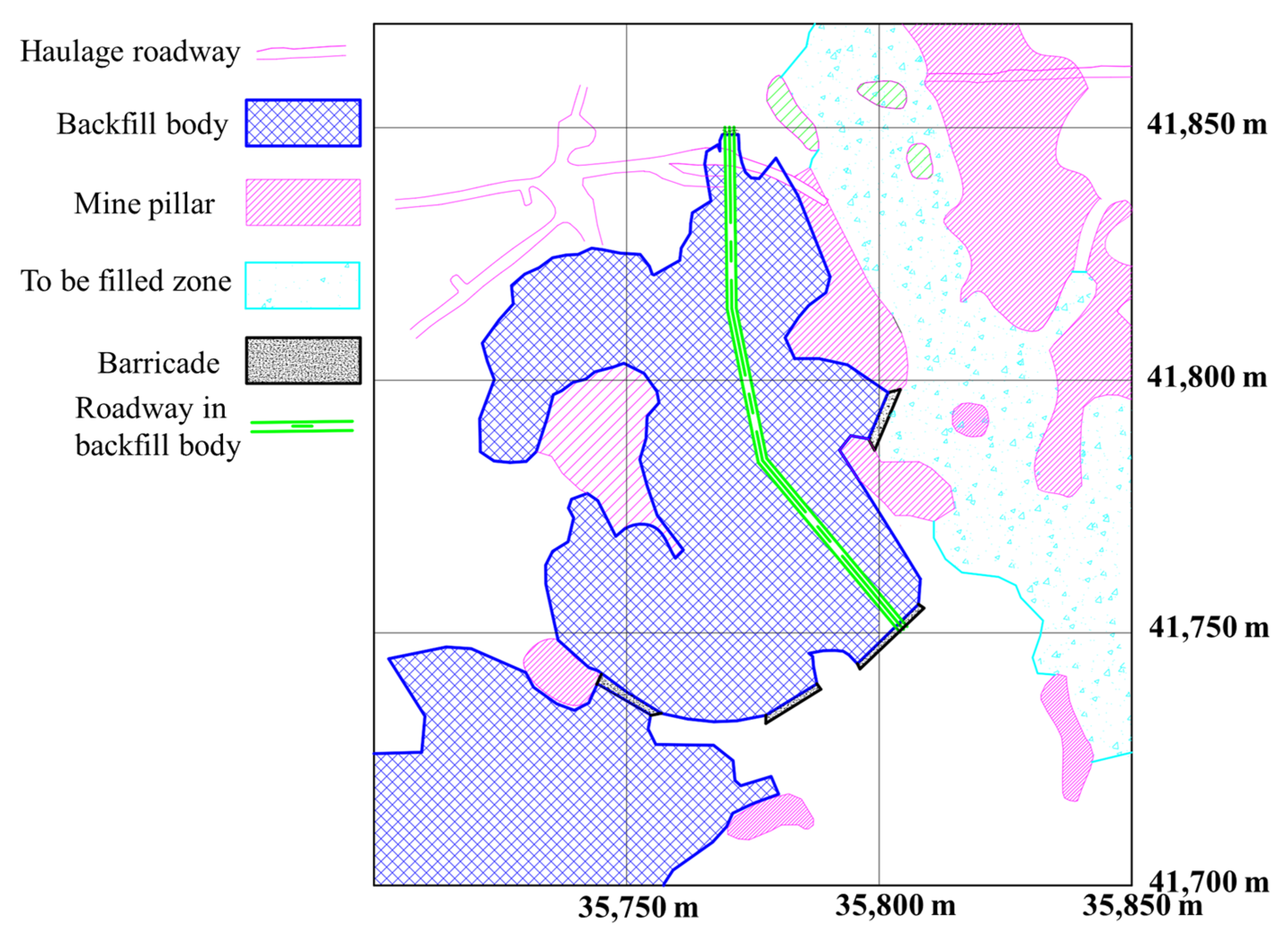
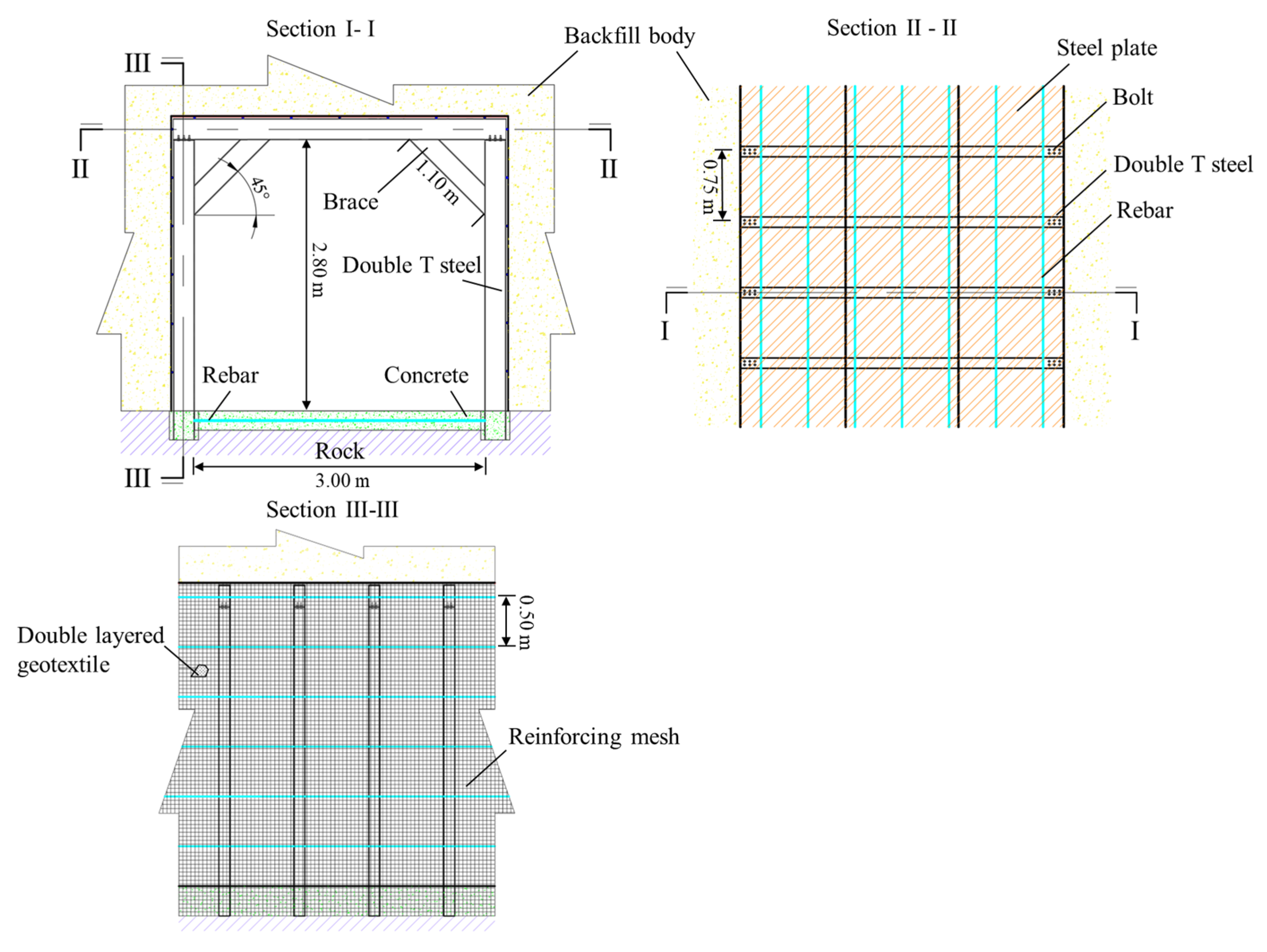
2. Engineering Background

The Xianglushan tungsten mine is located in Xiushui County, Jiangxi Province, China. It is a high-grade mine with a deposit of nearly 216,000 tons of tungsten, with a mean grade of 0.758%, giving it high economic value, and an annual scheelite output of over 8000 tons. Previously, the room and pillar mining method was the main technique used at the Xianglushan mine. However, due to the irrational mine planning during the early years of operation, massive irregular mine pillars were left, significantly impacting work safety and the environment. The goaf width ranges from 10 m to 30 m, and the mine pillar’s height ranges from 10 m to 25 m. It is estimated that the residual ore in those pillars is nearly ten million tons. On the one hand, these residual pillars could result in significant resource loss, but on the other hand, recovering them is challenging due to cracks induced by stress concentration in some pillars. Additionally, the roofs in some areas have collapsed, requiring considerable time and cost to reinforce the pillars. The cofferdam backfilling technique has been identified as an efficient approach to recovering the residual mine pillars in Xianglushan. Its technical specifications encompass an average daily mining production capacity of 137.2 tons, a 4.2% ore loss rate, and a dilution rate of 4.95%. The cutting ratio is approximately 1.41 m per thousand tons. However, cofferdam backfilling alters the local ventilation network, posing a safety threat to workers [34]. Therefore, a double-T steel-supported roadway has been designed as a channel for wind in the backfill body, as shown in Figure 1 (128-1# zone). Furthermore, the roadway in the backfill body provides a channel for material transportation. Based on the rules in the “Safety Regulation for Metal and Nonmetal Mines” (GB 16423-2020) [35] and operational needs for ventilation and transportation, the section size of the roadway was determined to be 3.00 m in length and 2.80 m in height, as depicted in Figure 2.
The process for assembling each supporting unit consists of two studs and one joist. Firstly, a groove is excavated on the floor using machinery. Then, two studs are inserted into the rock floor with a depth of 300.00 mm and linked horizontally by a 22.00 mm diameter rebar. The groove is then filled with concrete. The two studs and joist are assembled using bolts, and two 45-degree braces at the corners are used to reduce the joist’s deflection under load. The supporting units are arranged with an interval of 0.75 m along the roadway, and adjacent units are linked with a 22.00 mm diameter rebar. In accordance with the design requirements, the 28-day unconfined compressive strength (UCS) of the backfill material within the range from the roadway floor to 2 m above the roadway roof should not be less than 1.50 MPa. Additionally, considering cost efficiency, the strength of the upper backfill body must meet the self-support criteria when exposed at the side, set at 0.50 MPa. The side walls of the roadway are covered by double-layered geotextile and steel mesh, which help to control the horizontal deformation of the backfill body and provide a channel for water drainage. To ensure even load distribution at the roof level, a 4.00 mm thick steel plate is placed on the joist. After the backfilling of the adjacent goaf is completed, the mine pillar is recovered using the shrinkage stoping method.

3. Numerical Simulations

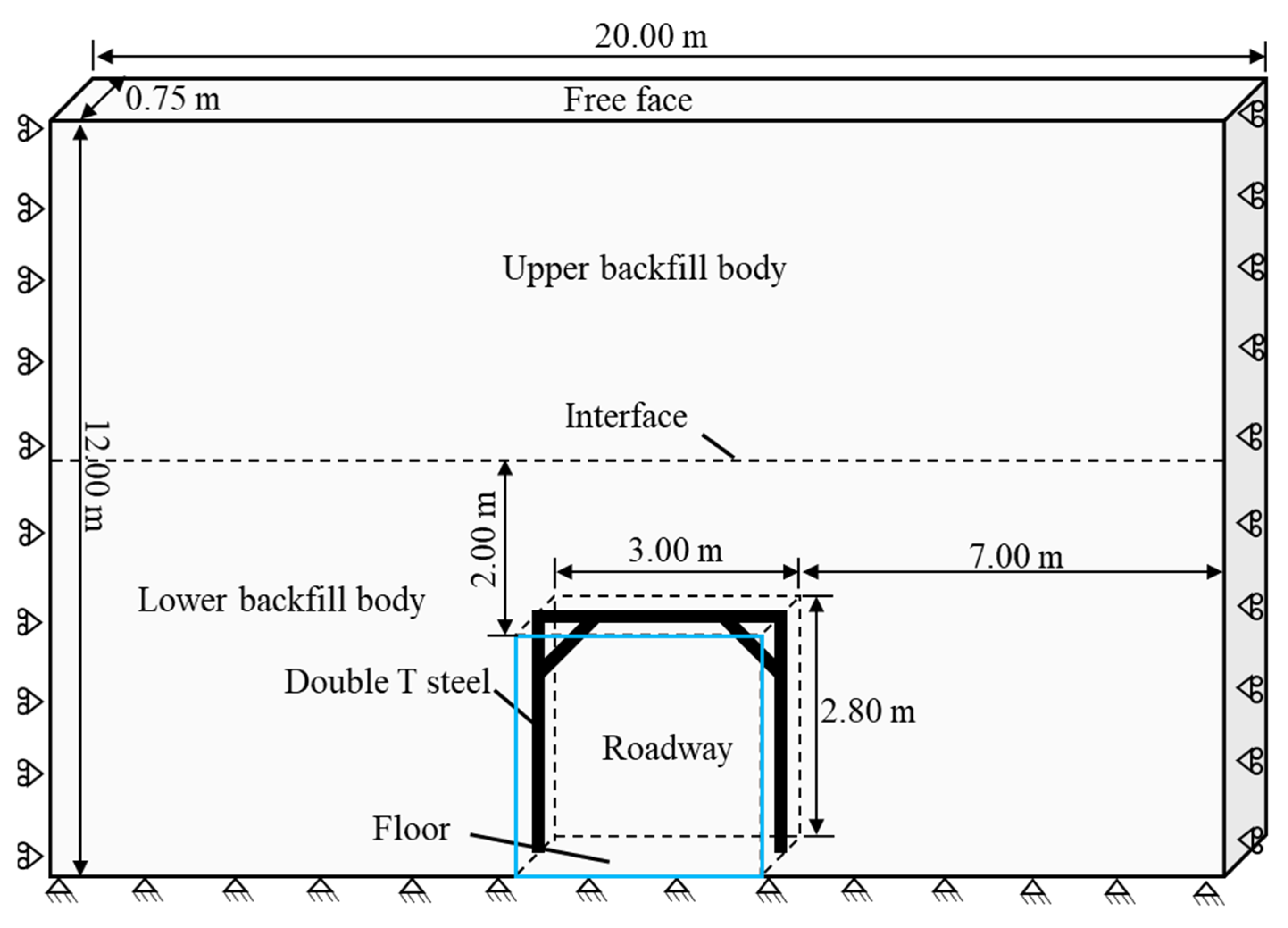
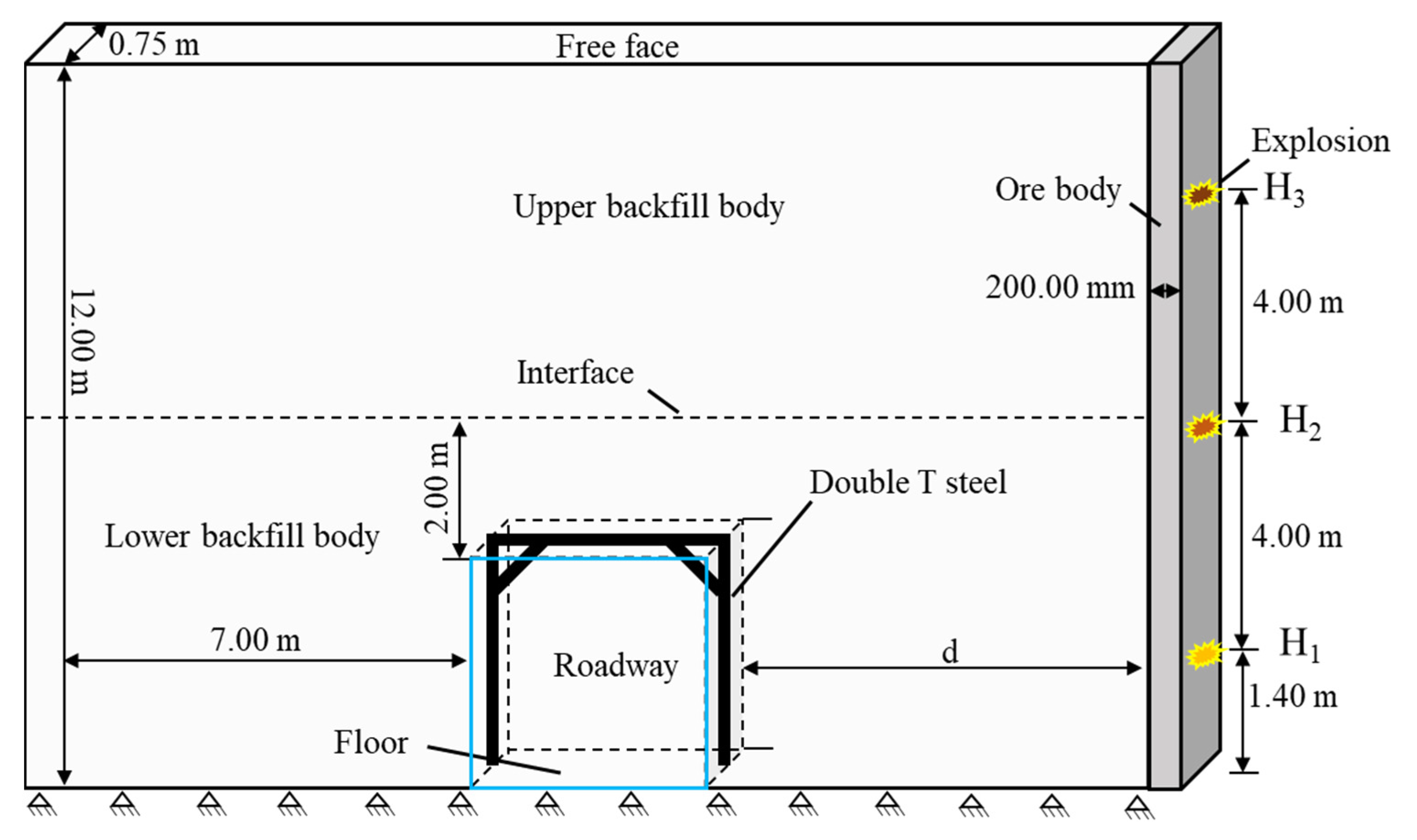
3.1. Boundary Conditions of Numerical Model

Numerical simulation is widely used in geotechnical engineering due to its advantages of high efficiency and low cost [36]. To evaluate the stability of the roadway in the backfill body, an implicit solution is used to obtain the mechanical response of the backfill body and double-T steel under static load. A sketch of the numerical model for the static load solution is shown in Figure 3. The entire model was 20.00 m in length, 12.00 m in height, and 0.75 m in width. Considering the cementing settlement of the backfill body and shallow conditions, the pressure from the roof was neglected. The normal displacement on the left, right, front, and back surfaces were constrained, and the bottom of the model was fully constrained. An interface was located 5.80 m from the bottom of the model, where the backfill below the interface had an unconfined compressive strength of 2.00 MPa, while the backfill above the interface had a UCS of 0.50 MPa. The double-T steel-supported roadway was situated in the central position of the lower boundary of the model.
To evaluate the stability of a double-T steel-supported roadway subjected to a blasting load, two factors were considered: the distance between the right side of the preformed roadway and the explosion (d) and the explosive position (H). The numerical simulation scheme is listed in Table 1, and twelve cases were considered. According to the current blasting practices in the Xianglushan mine (blasthole and row spacing are around 0.75 m), the quantity of explosive was determined to be 3.00 kg per blasthole. The single-cartridge specifications for No. 2 rock emulsion explosive are as follows: 36.00 mm in diameter, 200.00 mm in length, and a mass of 200.00 g. The 3.00 kg charge weight in Table 1 corresponds to a full-charge blasthole with a length of 3.00 m. As shown in Figure 4, the blasting load was applied to the right side of a 20.00 cm thickness orebody with an equivalent mass of TNT using the *LOAD_BLAST keyword during the dynamic load simulation phase. Damping is crucial in numerical simulations to prevent unrealistic vibrations, oscillations, and unstable behavior that can arise due to the absence of energy dissipation mechanisms present in real-world scenarios. In blasting simulations, elements may become distorted. In this simulation, hourglass control damping was employed to counteract this issue and enhance the stability of the simulation [37].
Figure 5 depicts the construction of a three-dimensional model using finite elements (case C1). The backfill body and mine pillar were meshed with 990,000 hexahedral elements, while the steel frame was meshed with 15,813 tetrahedral elements. The interaction between the steel frame and backfill body was achieved using the *CONTACT_AUTOMATIC_SURFACE_TO_SURFACE keyword. In a similar manner, the connections among these components within the steel frame were managed using a contact algorithm, with no sliding permitted at the points of connection. The numerical cases C10, C11, and C12 had the highest number of elements, consisting of 873,600 hexahedral elements and 15,813 tetrahedral elements.

3.2. Material Model and Parameters

The numerical simulation involved three materials: a mine pillar, a backfill body with a strength of 1.50 MPa and 0.50 Mpa, and Q235 steel [38,39]. Due to the need for both static and dynamic load simulations, the material model should be compatible with implicit–explicit conversion solutions. *MAT_PLASTIC_KINEMATIC is suitable for modeling isotropic and kinematic hardening plasticity, with the option of including rate effects [40]. This model has been widely used to simulate rock and steel and is very cost-effective; it is available for beam, shell, and solid elements. The material model for concrete is usually used to describe the mechanical behavior of the backfill body. *MAT_CONCRETE_DAMAGE_REL3 is a three-invariant model that uses three shear failure surfaces and includes damage and strain-rate effects. In this study, *MAT_PLASTIC_KINEMATIC was used to simulate the steel frame and the orebody, and *MAT_CONCRETE_DAMAGE_REL3 was applied to simulate the backfill body [41]. Most importantly, this material model has an option to automatically generate the model parameters based on the UCS of the concrete. More details on these two material models can be found in the LS-DYNA user manual [42]. The material properties are listed in Table 2.

4. Numerical Results and Discussion

4.1. Static Response of the Roadway under Gravitational Load

In practice, the double-T steel-supported roadway is constructed before the surrounding space is backfilled. The backfill body settles with bleeding water dewatering, creating a space between the upper backfill body surface and the stope roof. As a result, the external load in the backfill body in a shallow goaf is gravity, and the vertical stress distribution is shown in Figure 6 (Unit: Pa). Similar to an excavated roadway, the highest stresses in a preformed roadway are usually concentrated in the immediate vicinity of the excavation because the roadway creates a void in the rock mass, leading to a redistribution of stresses in the surrounding rock. The stresses near the preformed roadway are typically compressive, as the weight of the overlying backfill body causes it to be squeezed together. As the distance from the roadway increases, the stresses tend to be self-weight stresses. In most cases, regardless of whether there is support or not, most areas are under pressure. The maximum compressive vertical stress was 0.70 Mpa in the numerical case without support (Figure 6a). Geotechnical materials such as rock, soil, and backfill body have lower resistance to tension than to compression. It can be seen that tension stress occurred near the middle of the roadway roof in both cases, and the tension stress was below the materials’ tension strength. The steel frame resisted the settlement of the roadway roof very well, and the maximum vertical displacement of the entire model was 0.26 mm, which is less than the 0.275 mm obtained for the numerical case without double-T steel support. In general, regardless of the case, the preformed roadway was in a stable state due to the limited height of the backfill body.

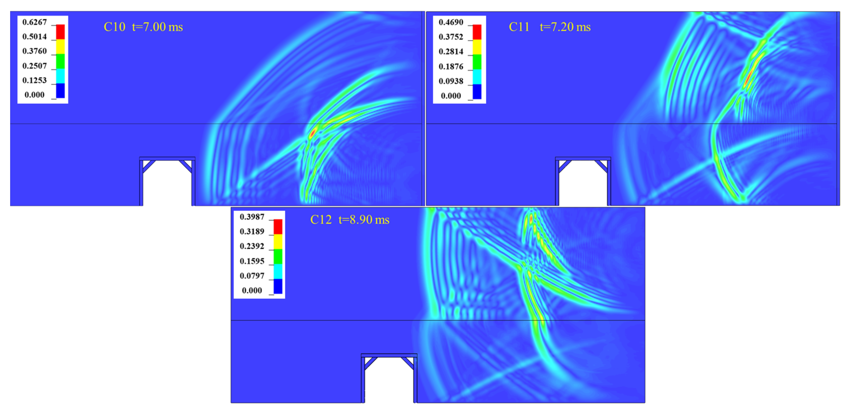
4.2. Dynamic Response of the Roadway Subjected to a Blasting Load

The dynamic response of a mine roadway refers to how the surrounding rocks and supporting structure react to external forces or loads. Because the mine pillar is shallowly buried, gravitational loads are not taken into consideration during the dynamic phase [43]. The numerical case C1 was taken as an example to analyze the dynamic response of the preformed roadway subjected to a blasting load. As shown in Figure 7 (unit: m/s), the blasting occurred at the bottom right of the model (1.40 m to the floor), and the blasting wave propagated toward the left. The first time the blasting wave reflection and transmission occurred was at the boundary between the lower backfill body and orebody. The semi-concentric circle-shaped velocity contour was disturbed, and thereafter, the blasting wave interface effect happened at the boundaries between two backfill bodies, the free faces, and the boundary between a steel frame and a lower backfill body. The velocity contour in the entire model showed disorder. Overall, the energy carried by the blasting wave gradually decayed as the propagating distance increased. The obvious characteristic of the blasting wave attenuation was that the blasting vibration velocity was decreasing. Partially, blasting wave superposition may enhance the local blast vibration, as the red zone shows in Figure 7 (at times of 4.10 and 7.10 ms).
In all, 17 monitoring points were arranged horizontally along the direction from the detonation to the preformed roadway with 0.50 m spacing to observe the peak particle velocity (PPV) evolution (monitored points seen in Figure 5). As shown in Figure 8, the maximum PPV reached 2.59 m/s on the right side of the lower backfill body. After that, the PPV decayed within 6.40 m of the distance from the detonation and enhanced within 1.60 m of the distance from the preformed roadway due to the blasting wave reflection caused by the free surface. When a steel frame is subjected to blasting, it can experience vibrations that may potentially lead to structural damage or failure. In this scenario, four monitoring points were set up to track the time history of vibration around the preformed roadway (Figure 9). As shown in Figure 7, points P1 and P2 were located at the midpoint of the joist and right stud of the steel frame, while points P3 and P4 were located on the free face of the backfill body. The PPV values at these monitoring points (P1, P2, P3, and P4) were 0.32 m/s, 0.72 m/s, 0.29 m/s, and 0.57 m/s, respectively. Generally, the blasting wave attenuation in a steel frame is slower than that in its surrounding backfill body. In the case of a steel frame and the supported backfill body, blasting waves will travel through each material differently due to their different properties. Steel is a very dense and elastic material, which means that blasting waves can travel through it quickly and efficiently while maintaining their energy for longer periods of time. On the other hand, the backfill body is less dense and less elastic than steel, which means that blasting waves will travel through it more slowly and with less efficiency, losing energy more quickly as they propagate. Overall, in numerical case C1, no damage was observed in the steel frame or the backfill body around the roadway.

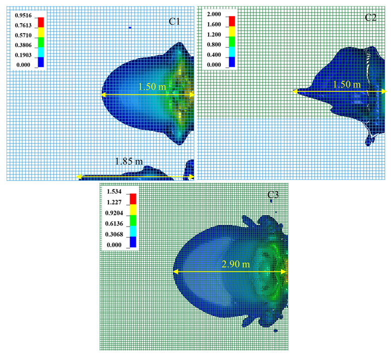
4.3. Blasting-Induced Damage in Backfill Bodies

Besides ensuring the stability of the preformed roadway, it is crucial to prevent damage caused by blasting in the backfill body when conducting a blasting operation nearby. This significantly affects the safety of the working environment and subsequent ore handling. For instance, if the backfill material mixes with the ore stack, it can increase the ore dilution rate. Furthermore, the collapse of a backfill body can create safety hazards for workers, especially if the collapse occurs unexpectedly or if there is a risk of further collapse. Contaminated ore can be more difficult to process and may require additional processing steps or equipment, which can increase costs and reduce efficiency. In numerical simulation cases, the main factor that affects blasting-induced damage in the backfill body near the orebody is the explosive position.
As shown in Figure 10, three cases of blasting-induced damage (scaled damage measure described in LS-DYNA users’ manual) in the backfill body were extracted, where the value in the fringe ranged from 0 to 1 as the material transitioned from the yield failure surface to the maximum failure surface and, thereafter, ranged from 1 to 2 as the material ranged from the maximum failure surface to the residual failure surface [42]. Therefore, elements with fringe ranges from 1 to 2 can be treated as failures. With the upward movement of the explosive position, the range of the damage zone in the backfill body shrunk first and then increased. The degree of damage decayed as the distance away from the detonation increased.
In numerical simulation case 1, the scaled damage measure ranged from 0 to 0.95, and the maximum dimensions of the blasting load-induced damage zone in the horizontal and vertical directions were 1.50 m and 1.70 m, respectively. Additionally, a strip of damage zone with a length of 1.85 m formed near the bottom. When the detonation moved to the position 5.40 m away from the bottom, the damage zone distribution nearly formed a triangle, and its size was obviously smaller than in case 1. The reason for this is as follows: on the one hand, the blasting wave reflection from the bottom boundary and the right boundary of the backfill body in case 1 was stronger than in case 2. On the other hand, the explosive position in case 1 was closer to the constrained bottom boundary than in case 2, which drives horizontal shear action and generates a damage zone at the bottom.
Due to the weak strength of the upper backfill body, the largest damage zone occurred in numerical case 3 as expected, and its horizontal length reached 2.90 m. Although the explosive position was near the free face in numerical simulation case 3, the maximum value of the scaled damage measure was only 1.53, which is less than that in case 2. Obviously, elements near the free surface are more prone to moving than those near the constrained boundary. The free surface resulted in blasting wave superposition around the damage zone and made it form a large zone of damage. Due to the limited energy of the blasting wave, the degree of damage in case 3 was lower than in case 2. In terms of material failure, only a vertical strip zone of 60.00 mm in width near the backfill body boundary failed in numerical simulation case 2, which is totally acceptable in practice.
Sacrificial pillars, sometimes referred to as mine walls, are commonly used to protect the backfill body by absorbing the shock and energy from a blast. They are particularly useful when the backfill is weak or has a high risk of collapse. However, it is unreasonable to use sacrificial pillars in cases where mine pillars are being recovered. Therefore, it is crucial to implement reasonable blasting parameters to reduce the risk of backfill body collapse. In this study, it can be inferred that a charge weight of 3.00 kg per delay interval poses no threat to backfill body stability. As a result, the optimal blasthole spacing in engineering practice should be around 0.75 m.

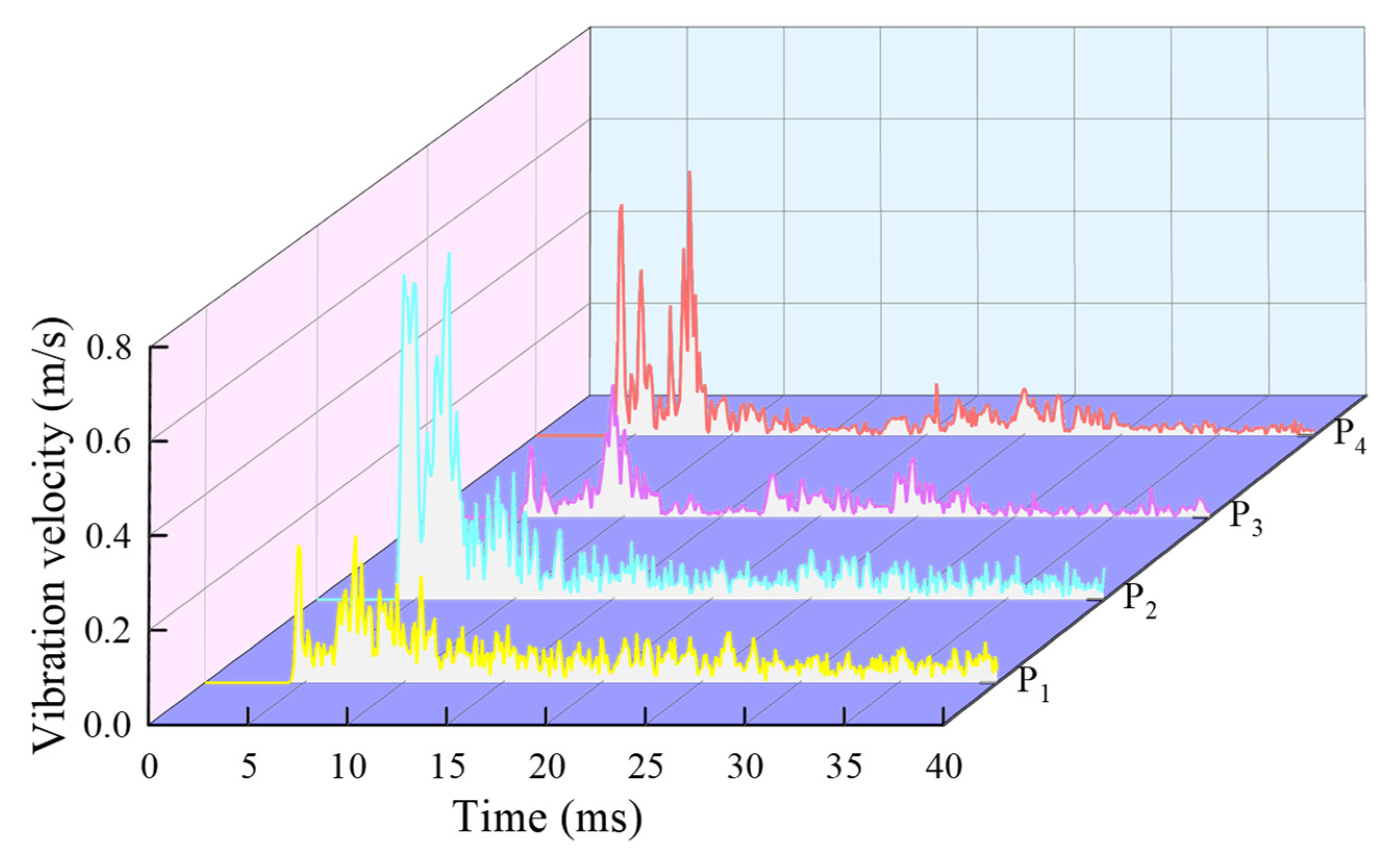
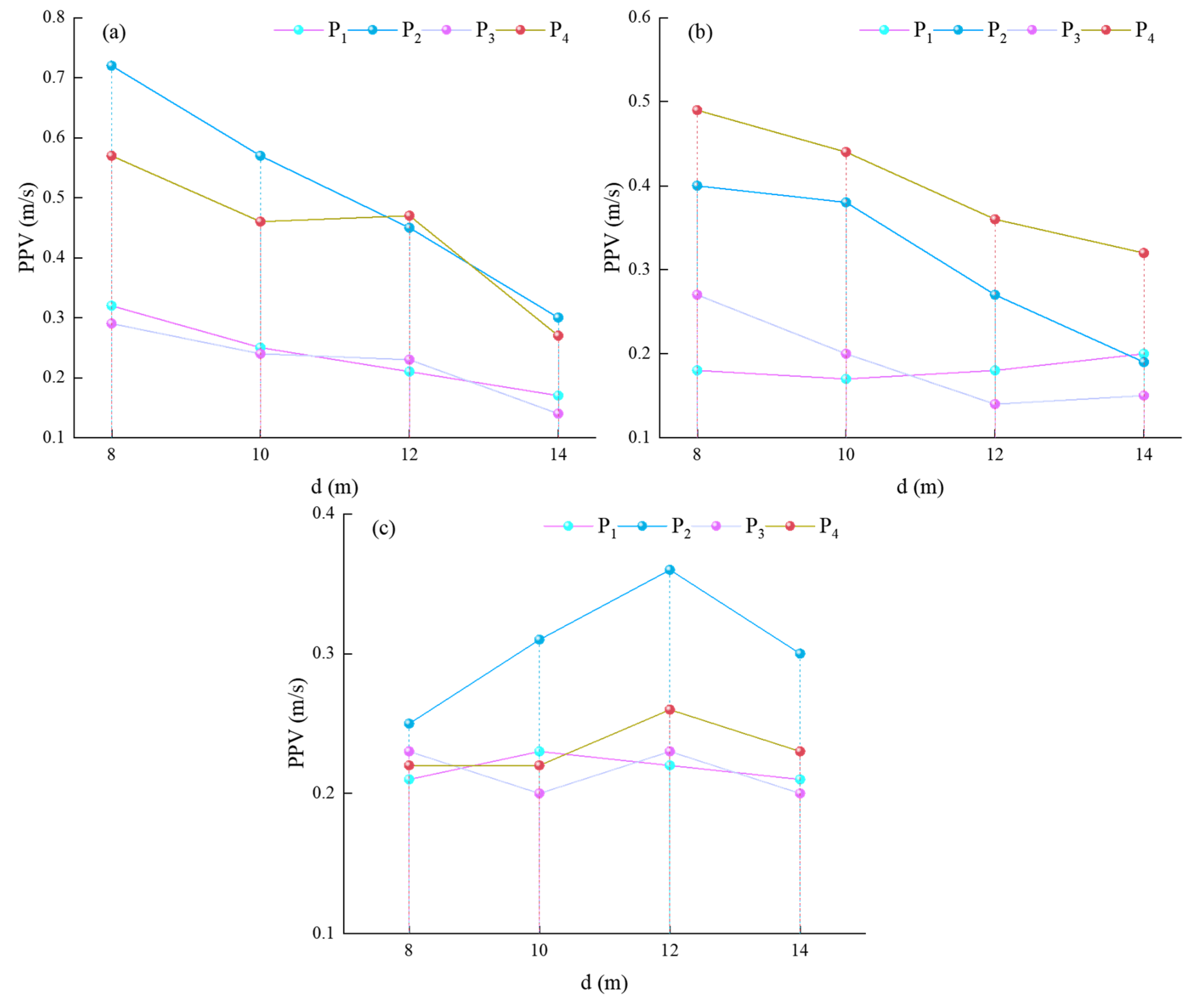
4.4. Blasting Vibration Velocity

The distance between the blast site and the preformed roadway is a crucial factor that affects the velocity of vibrations. Figure 11 demonstrates the effect of the distance between the explosive and the preformed roadway on the peak particle velocities (PPVs) of four monitored points. As the distance increased, more energy was absorbed by the backfill body during the propagation of blasting waves toward the left, resulting in a negative relationship between the PPVs and d when H was 1.40 m and 5.40 m. However, when H was 9.40 m, the effect of d on the PPVs was not obvious due to blasting wave attenuation (Figure 11c). Moreover, the position of the explosive also played a significant role in the blasting vibration velocity of the model. Figure 12 depicts that the blasting vibration contour corresponded to the time when the blasting waves reached point P2. In a particular numerical model, the explosive had the longest relative distance to the preformed roadway when H was 9.40 m. Thus, the effect of d on the PPVs was not apparent due to blasting wave attenuation. Softer materials, such as a low-strength backfill body, tend to absorb more of the energy from the blast, reducing the velocity of vibrations. On the other hand, harder materials, such as a high-strength backfill body, transmit the vibrations more efficiently, allowing them to travel further and faster. Therefore, the global blasting vibration velocity level in the entire model decreases as the explosive position moves upwards. Point P2 was closer to the explosive than P1, resulting in stronger stud vibrations than joist vibrations in the steel frame. Similarly, the vibration velocity of P4 was higher than that of P3 in the lower backfill body. The relative vibration velocity between two points, P1 (or P2) and P3 (or P4), varied with the d value, as shown in Figure 11.
Steel is a material that is known for its high stiffness and density, which makes it capable of vibrating at higher frequencies than the backfill body. On the other hand, the backfill body is less dense and less stiff, which means that it has a lower vibration frequency compared to steel. As shown in Figure 6, stress concentration can already occur at the connection of the brace and stud when subjected to gravitational load. This means that the quality of the connection between the brace and stud should be carefully considered during mine pillar recovery to ensure that the structure is able to withstand the load. Moreover, the blasting load induced high-frequency vibrations in the steel frame, which further emphasizes the importance of ensuring the connection quality of the welding spot and screw in the steel frame. The welding spot and screw connection should be carefully inspected to ensure that they are strong enough to withstand the high-frequency vibrations induced by the blasting load.

5. Engineering Practice of Mine Pillar Recovery

A field trial was conducted within the 128-1 zone, situated in the northeastern part of the broader 128 zone, encompassing an area spanning approximately 5155 m2. This particular area of interest is characterized by a mining void that presently exists at elevations ranging from 631 to 646 m. The average height of the roof measures around 12 m. Notably, the majority of the mining region lies near the surface, with depths generally not exceeding 20 m. Positionally, the northern boundary of the mining area seamlessly connects to the primary ventilation shaft, strategically located near the northern 4 zone. On the eastern side, the mining region shares its boundary with the north 4 and north 3 zones, both of which have previously undergone comprehensive backfilling operations. Within the 128-1 zone, a preformed roadway has been meticulously constructed within the confines of the backfill mass.
As part of the operational procedures, mine pillar recovery was undertaken utilizing shrinkage stoping techniques. In light of safety considerations and the prevention of potential hazards like rockfalls or structural collapse, it is of paramount importance to maintain the stability of the backfill mass. This ensures that a secure working environment is upheld for personnel operating within the zone. An observation of Figure 13 reveals that the surface of the exposed backfill mass presented a relatively level profile. There was minimal evidence of collapse or deformation near the surface, a feature that harmoniously corresponds with the outcomes derived from the numerical simulations. In practical scenarios, the slight collapse of the backfill body is quite acceptable, and the uneven surface offers advantages when coupling with the adjacent backfill material during the second step of backfilling.
In essence, the comprehensive details elucidated above underscore the intricacies of the trial conducted in the 128-1 zone. The integration of both practical field observations and numerical analysis is imperative for effective mine management and the continual assurance of safety within these mining operations.

6. Conclusions

Aiming to provide guidance on recovering tungsten from mine pillars and enhancing mining safety for workers at the Xianglushan mine, a numerical simulation approach was utilized to analyze the mechanical response of a steel-framed preformed roadway under a backfill body. The blasting vibration velocity and blasting-induced damage in the backfill body were analyzed, and the main conclusions of this paper can be summarized as follows:
(1)
The preformed roadway remained stable under both gravitational load and blasting dynamic impact with a charge of 3.00 kg per blasthole rock emulsion explosive.
(2)
The backfill body posed a low risk when subjected to blasting impact. In terms of material failure, the largest failure zone was only a vertical strip zone of 60.00 mm in width near the backfill body, which is totally acceptable in engineering practice.
(3)
The blasting vibration attenuation in the steel frame was slower than that in the backfill body, and the vibration frequency in the steel frame was higher than that in the backfill body. Therefore, the quality of the welding spot and screw connection in the steel frame during mine pillar recovery should be carefully considered.

Author Contributions

Conceptualization, H.D. and F.W.; methodology, F.W. and R.O.; software, F.W.; validation, H.D., F.W. and R.O.; formal analysis, H.D. and F.W.; investigation, H.D., F.W. and R.O.; data curation, F.W.; writing—original draft preparation, F.W.; writing—review and editing, H.D. and F.W.; visualization, F.W.; supervision, H.D. All authors have read and agreed to the published version of the manuscript.

Funding

This research received no external funding.

Data Availability Statement

The data that support the findings of this study are available on request from the corresponding author.

Conflicts of Interest

The authors declare no conflict of interest.

References

  1. Li, X.; Zhao, Y.; Guo, Z.; Liu, Y.; Wang, H.; Zhang, J.; Yi, D.; Cao, Y.; Yang, X.; Liu, B.; et al. Influence of different substrates on the microstructure and mechanical properties of WC-12Co cemented carbide fabricated via laser melting deposition. Int. J. Refract. Met. Hard Mater. 2022, 104, 105787. [Google Scholar] [CrossRef]
  2. Han, Z.; Golev, A.; Edraki, M. A Review of Tungsten Resources and Potential Extraction from Mine Waste. Minerals 2021, 11, 701. [Google Scholar] [CrossRef]
  3. Leal-Ayala, D.R.; Allwood, J.M.; Petavratzi, E.; Brown, T.J.; Gunn, G. Mapping the global flow of tungsten to identify key material efficiency and supply security opportunities. Resour. Conserv. Recycl. 2015, 103, 19–28. [Google Scholar] [CrossRef]
  4. Barume, B.; Naeher, U.; Ruppen, D.; Schütte, P. Conflict minerals (3TG): Mining production, applications and recycling. Curr. Opin. Green Sustain. Chem. 2016, 1, 8–12. [Google Scholar] [CrossRef]
  5. Zhang, Y.; Ni, P. Design optimization of room and pillar mines: A case study of the Xianglushan tungsten mine. Q. J. Eng. Geol. Hydrogeol. 2018, 51, 352–364. [Google Scholar] [CrossRef]
  6. Navarro Torres, V.F.; Dinis da Gama, C.; Costa e Silva, M.; Neves, P.F.; Xie, Q. Comparative stability analyses of traditional and selective room-and-pillar mining techniques for sub-horizontal tungsten veins. Int. J. Miner. Metall. Mater. 2011, 18, 1–8. [Google Scholar] [CrossRef]
  7. Mark, C.; Gauna, M. Preventing roof fall fatalities during pillar recovery: A ground control success story. Int. J. Min. Sci. Technol. 2017, 27, 107–113. [Google Scholar] [CrossRef]
  8. Sun, Q.; Zhang, J.; Zhou, N. Study and discussion of short- strip coal pillar recovery with cemented paste backfill. Int. J. Rock Mech. Min. Sci. 2018, 104, 147–155. [Google Scholar] [CrossRef]
  9. Cao, S.; Xue, G.; Yilmaz, E.; Yin, Z.; Yang, F. Utilizing concrete pillars as an environmental mining practice in underground mines. J. Clean. Prod. 2021, 278, 123433. [Google Scholar] [CrossRef]
  10. Mallı, T.; Yetkin, M.E.; Özfırat, M.K.; Kahraman, B. Numerical analysis of underground space and pillar design in metalliferous mine. J. Afr. Earth Sci. 2017, 134, 365–372. [Google Scholar] [CrossRef]
  11. Yang, C.; Zhou, K.; Gao, R.; Xiong, X. Numerical investigation of the dynamic response of a preconditioned roof in an underground mine: A case study of mining environment regeneration. Soil Dyn. Earthq. Eng. 2021, 140, 106457. [Google Scholar] [CrossRef]
  12. Zhou, N.; Yan, H.; Jiang, S.; Sun, Q.; Ouyang, S. Stability Analysis of Surrounding Rock in Paste Backfill Recovery of Residual Room Pillars. Sustainability 2019, 11, 478. [Google Scholar] [CrossRef]
  13. Yang, L.; Li, J.; Liu, H.; Jiao, H.; Yin, S.; Chen, X.; Yu, Y. Systematic review of mixing technology for recycling waste tailings as cemented paste backfill in mines in China. Int. J. Miner. Metall. Mater. 2023, 30, 1430–1443. [Google Scholar] [CrossRef]
  14. Kefeni, K.K.; Msagati, T.A.M.; Mamba, B.B. Acid mine drainage: Prevention, treatment options, and resource recovery: A review. J. Clean. Prod. 2017, 151, 475–493. [Google Scholar] [CrossRef]
  15. Singalreddy, S.P.; Cui, L.; Fang, K. Spatiotemporal evolution of thermo-hydro-mechanical-chemical processes in cemented paste backfill under interfacial loading. Int. J. Min. Sci. Technol. 2022, 32, 1207–1217. [Google Scholar] [CrossRef]
  16. Hefni, M.; Hassani, F. Experimental development of a novel mine backfill material: Foam mine fill. Minerals 2020, 10, 564. [Google Scholar] [CrossRef]
  17. Skrzypkowski, K. Decreasing Mining Losses for the Room and Pillar Method by Replacing the Inter-Room Pillars by the Construction of Wooden Cribs Filled with Waste Rocks. Energies 2020, 13, 3564. [Google Scholar] [CrossRef]
  18. Kermani, M.; Hassani, F.P.; Aflaki, E.; Benzaazoua, M.; Nokken, M. Evaluation of the effect of sodium silicate addition to mine backfill, Gelfill—Part 1. J. Rock Mech. Geotech. Eng. 2015, 7, 266–272. [Google Scholar] [CrossRef]
  19. Wang, X.; Zhao, B.; Zhang, Q. Cemented backfill technology based on phosphorous gypsum. J. Cent. South Univ. Technol. 2009, 16, 285–291. [Google Scholar] [CrossRef]
  20. Zhou, S.; Li, X.; Zhou, Y.; Min, C.; Shi, Y. Effect of phosphorus on the properties of phosphogypsum-based cemented backfill. J. Hazard. Mater. 2020, 399, 122993. [Google Scholar] [CrossRef]
  21. Chen, Q.; Zhang, Q.; Qi, C.; Fourie, A.; Xiao, C. Recycling phosphogypsum and construction demolition waste for cemented paste backfill and its environmental impact. J. Clean Prod. 2018, 186, 418–429. [Google Scholar] [CrossRef]
  22. Cao, S.; Yilmaz, E.; Song, W. Fiber type effect on strength, toughness and microstructure of early age cemented tailings backfill. Constr. Build. Mater. 2019, 223, 44–54. [Google Scholar] [CrossRef]
  23. Chen, X.; Shi, X.; Zhou, J.; Yu, Z.; Huang, P. Determination of mechanical, flowability, and microstructural properties of cemented tailings backfill containing rice straw. Constr. Build. Mater. 2020, 246, 118520. [Google Scholar] [CrossRef]
  24. Dewing, K.; Sharp, R.J.; Muraro, T. Exploration History and Mineral Potential of the Central Arctic Zn-Pb District, Nunavut. Arctic 2006, 59, 415–427. [Google Scholar] [CrossRef]
  25. Cluff, D.L.; Kazakidis, V.N. Opportunities and constraints of engineering frozen backfill for underground mining applications in permafrost. In Proceedings of the ISCORD 2013: Planning for Sustainable Cold Regions, Anchorage, Alaska, 2–5 June 2013; American Society of Civil Engineers: Reston, VI, USA, 2013; pp. 175–190. [Google Scholar]
  26. Jiang, H.; Fall, M. Yield stress and strength of saline cemented tailings in sub-zero environments: Portland cement paste backfill. Int. J. Miner. Process. 2017, 160, 68–75. [Google Scholar] [CrossRef]
  27. Hou, C.; Zhu, W.; Yan, B.; Guan, K.; Du, J. The effects of temperature and binder content on the behavior of frozen cemented tailings backfill at early ages. Constr. Build. Mater. 2020, 239, 117752. [Google Scholar] [CrossRef]
  28. Zhang, Q.; Tao, Z.; Yang, C.; Guo, S.; He, M.; Zhang, C.; Niu, H.; Wang, C.; Wang, S. Experimental and numerical investigation into the non-explosive excavation of tunnels. J. Rock Mech. Geotech. Eng. 2022, 14, 1885–1900. [Google Scholar] [CrossRef]
  29. Yang, C.; Hassani, F.; Zhou, K.; Zhang, Q.; Wang, F.; Gao, F.; Topa, A. Numerical investigation of TBM disc cutter cutting on microwave-treated basalt with an unrelieved model. Arch. Civ. Mech. Eng. 2022, 22, 147. [Google Scholar] [CrossRef]
  30. Song, J.; Luo, J.; Zhou, A.; Ou, R.; Ning, Y.; Lin, W. Application of backfill with cofferdam packing bags in Xianglushan tungsten ore. Min. Res. Dev. 2015, 35, 1–4. [Google Scholar]
  31. Zhu, Z.; Mohanty, B.; Xie, H. Numerical investigation of blasting-induced crack initiation and propagation in rocks. Int. J. Rock Mech. Min. 2007, 44, 412–424. [Google Scholar] [CrossRef]
  32. Yu, Y.; Ma, L.; Zhang, D. Characteristics of Roof Ground Subsidence While Applying a Continuous Excavation Continuous Backfill Method in Longwall Mining. Energies 2020, 13, 95. [Google Scholar] [CrossRef]
  33. Emad, M.Z.; Mitri, H.; Kelly, C. Dynamic model validation using blast vibration monitoring in mine backfill. Int. J. Rock Mech. Min. 2018, 107, 48–54. [Google Scholar] [CrossRef]
  34. Zhou, A.; Luo, J.; Song, J.; Ou, R.; Ning, Y.; Lin, W. Experimental study on filling technology with cofferdam bags in Xianglushan tungsten mine. Min. Res. Dev. 2015, 35, 1–4. [Google Scholar]
  35. GB 16423-2020; Safety Rerulations for Melal and Non-Metal Mines. Emergency Manaement Department of the People’s Repubic of China, Stae Admimsration for Market Reaulation of the People’s Repubic of China: Beijing, China, 2020.
  36. Gao, F.; Tang, L.; Yang, C.; Yang, P.; Xiong, X.; Wang, W. Blasting-induced rock damage control in a soft broken roadway excavation using an air deck at the blasthole bottom. Bull. Eng. Geol. Environ. 2023, 82, 97. [Google Scholar] [CrossRef]
  37. Kiakojouri, F.; Tavakoli, H.R.; Sheidaii, M.R.; De Biagi, V. Numerical analysis of all-steel sandwich panel with drilled I-core subjected to air blast scenarios. Innov. Infrastruct. Solut. 2022, 7, 320. [Google Scholar] [CrossRef]
  38. Yao, S.; Zhang, D.; Lu, Z.; Lin, Y.; Lu, F. Experimental and numerical investigation on the dynamic response of steel chamber under internal blast. Eng. Struct. 2018, 168, 877–888. [Google Scholar] [CrossRef]
  39. Guanghong, M.; Yu, H.; Jiuying, A.; Qiuyue, M.; Zhihao, S.; Honghao, M.; Zhaowu, S. Numerical simulation of explosive welding of metal tube and rod based on different algorithms. Trans. China Weld. Inst. 2022, 43, 64–71. [Google Scholar]
  40. Wang, X.; Li, J.; Zhao, X.; Liang, Y. Propagation characteristics and prediction of blast-induced vibration on closely spaced rock tunnels. Tunn. Undergr. Space Technol. 2022, 123, 104416. [Google Scholar] [CrossRef]
  41. Li, G.; Deng, G.-Z.; Ma, J. Numerical modelling of the response of cemented paste backfill under the blasting of an adjacent ore stope. Constr. Build. Mater. 2022, 343, 128051. [Google Scholar] [CrossRef]
  42. Halquist, J. LS-DYNA Keyword User’s Manual Version 971; Livermore Software Technology Corporation: Livermore, CA, USA, 2007. [Google Scholar]
  43. Deng, X.F.; Zhu, J.B.; Chen, S.G.; Zhao, Z.Y.; Zhou, Y.X.; Zhao, J. Numerical study on tunnel damage subject to blast-induced shock wave in jointed rock masses. Tunn. Undergr. Space Technol. 2014, 43, 88–100. [Google Scholar] [CrossRef]
Figure 1. Layout of double-T steel-supported roadway in backfill body.
Processes 11 02548 g001
Figure 2. Design drawing of double-T steel-supported roadway.
Processes 11 02548 g002
Figure 3. Sketch of numerical model for static load solution.
Processes 11 02548 g003
Figure 4. Sketch of numerical model for dynamic load solution.
Processes 11 02548 g004
Figure 5. Numerical model configuration of case C1.
Processes 11 02548 g005
Figure 6. Vertical stress distribution under the static load: (a) Without support; (b) with support.
Processes 11 02548 g006
Figure 7. Numerical simulation results of blasting vibration velocity.
Processes 11 02548 g007
Figure 8. PPV variation with the distance from the detonation.
Processes 11 02548 g008
Figure 9. Time history of vibration velocity.
Processes 11 02548 g009
Figure 10. Blasting-induced damage in backfill bodies.
Processes 11 02548 g010
Figure 11. Effect of d on four monitored points’ PPV: (a) H = 1.40 m; (b) H = 5.40 m; (c) H = 9.40 m).
Processes 11 02548 g011
Figure 12. Velocity contours in cases with d = 14.00 m.
Processes 11 02548 g012
Figure 13. Image of exposed backfill body after mine pillar recovery.
Processes 11 02548 g013
Table 1. Numerical simulation scheme.
Case No.The Distance between the Right Side of the
Preformed Roadway and the Explosion, d (m)
Explosive Position,
H (m)
C181.4
C285.4
C389.4
C4101.4
C5105.4
C6109.4
C7121.4
C8125.4
C9129.4
C10141.4
C11145.4
C12149.4
Table 2. Material properties.
Material TypeDensity (kg/m3)Elastic Modulus (Gpa)Poisson’s RatioUCS (Mpa)
Orebody2705.0042.200.160.80
Steel 7850.00210.000.3235.00 (Yield strength)
Upper backfill body1540.00-0.200.50 (28 day)
Lower backfill body1780-0.231.50 (28 day)
Disclaimer/Publisher’s Note: The statements, opinions and data contained in all publications are solely those of the individual author(s) and contributor(s) and not of MDPI and/or the editor(s). MDPI and/or the editor(s) disclaim responsibility for any injury to people or property resulting from any ideas, methods, instructions or products referred to in the content.

