1. Introduction
Rapid population growth and economic expansion result in a greater requirement for energy consumption. Oil, gas and geothermal energy are the two main underground resources which have a significant influence on the supply of the global energy market [
1,
2,
3]. Transport and retention of suspended granules in porous or fracture media are commonly encountered in oil, gas and geothermal reservoirs [
4,
5,
6,
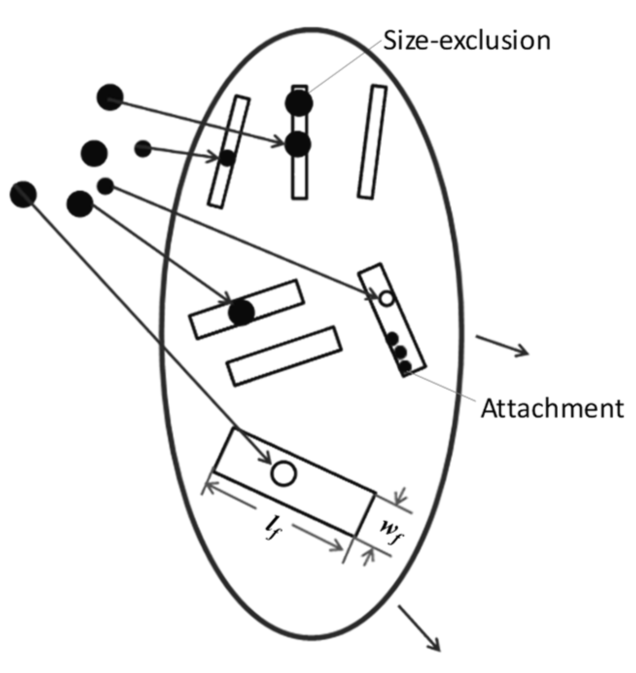
7]. Size exclusion is the main granule retention mechanism during oil and gas production, reservoir well drilling, water storage in geothermal reservoirs, water disposal produced from oilfields, multi-phase heat transfer behaviors, hydraulic fracturing, injectivity impairment in oil, gas reservoirs, granules invasion and fines migration in reservoirs, etc. [
8,
9,
10,
11,
12,
13,
14,
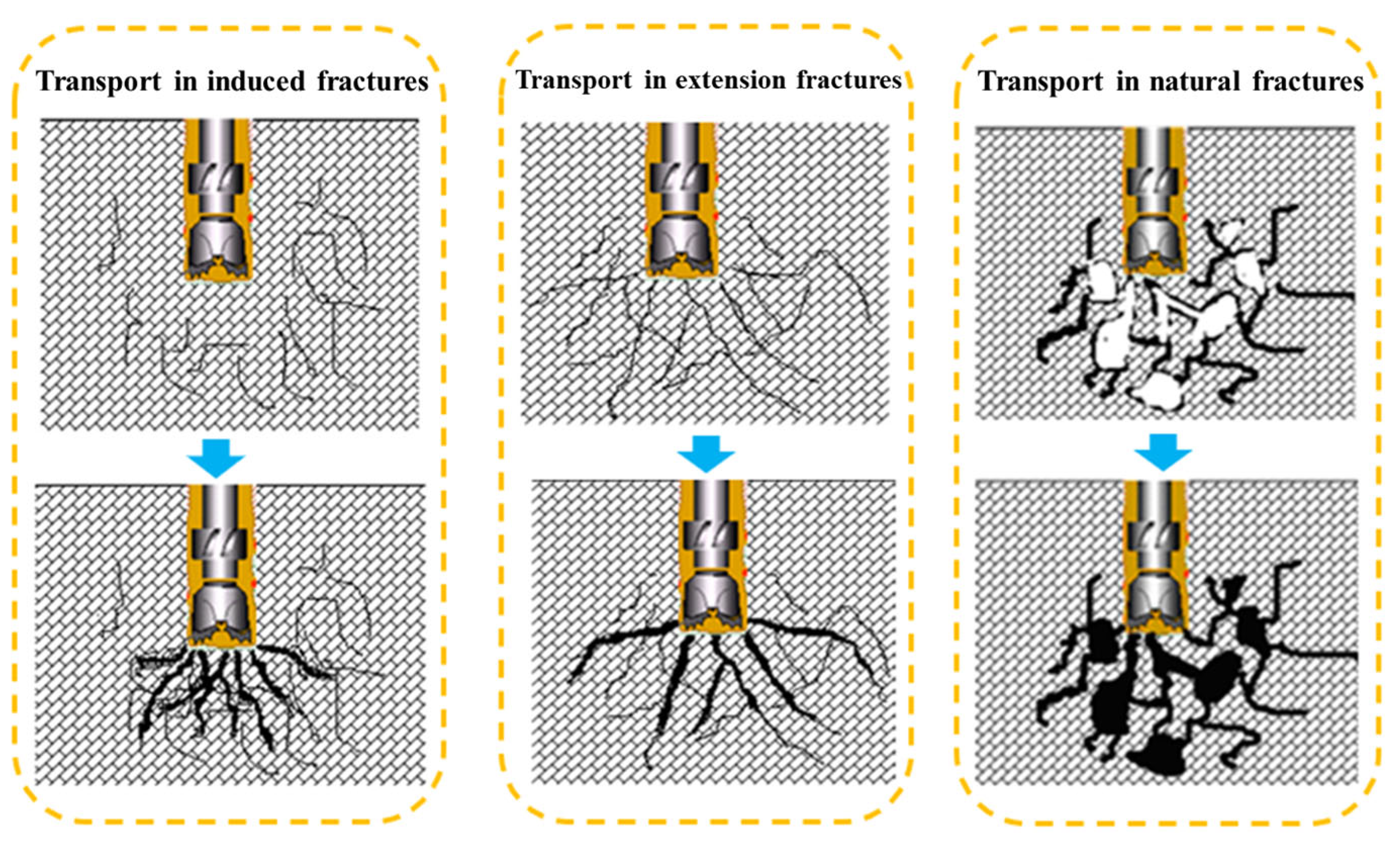
15]. In the drilling of oil, gas and geothermal reservoirs, granules retention frequently happens during the invasion of granular suspension (e.g., drilling fluid and completion fluid) (
Figure 1). It can lead to significant permeability damage and productivity decline, which seriously hinders the efficient development of oil, gas and geothermal resources [
16,
17,
18].
A comprehensive understanding and quantification of suspended granule flow and retention behaviors are of great importance for the forecasting and control of permeability damage and subsequent productivity decline. Large amounts of studies have been carried out on the flow and capture behaviors of particulate suspension in the oil, gas and geothermal reservoirs with porous media properties. For porous media, granule retention by size exclusion is dependent on the sizes of the granule and pore system. The quantification of the transport and capture behaviors of granules in porous media requires the characterization of the size distribution of granules and pores, which is described by stochastic models [
19,
20]. There are a series of stochastic approaches for the description of the suspended granule flow in porous media, including population balance models, random-walk models, mean-field models, CFD models and Boltzmann models [
21,
22,
23,
24]. Pore size distributions, filtration coefficient and suspended and captured granules concentrations have been accounted for in these models [
25,
26]. Exact upscaling is allowed for the mono-sized suspended granule flow in the porous media [
26].
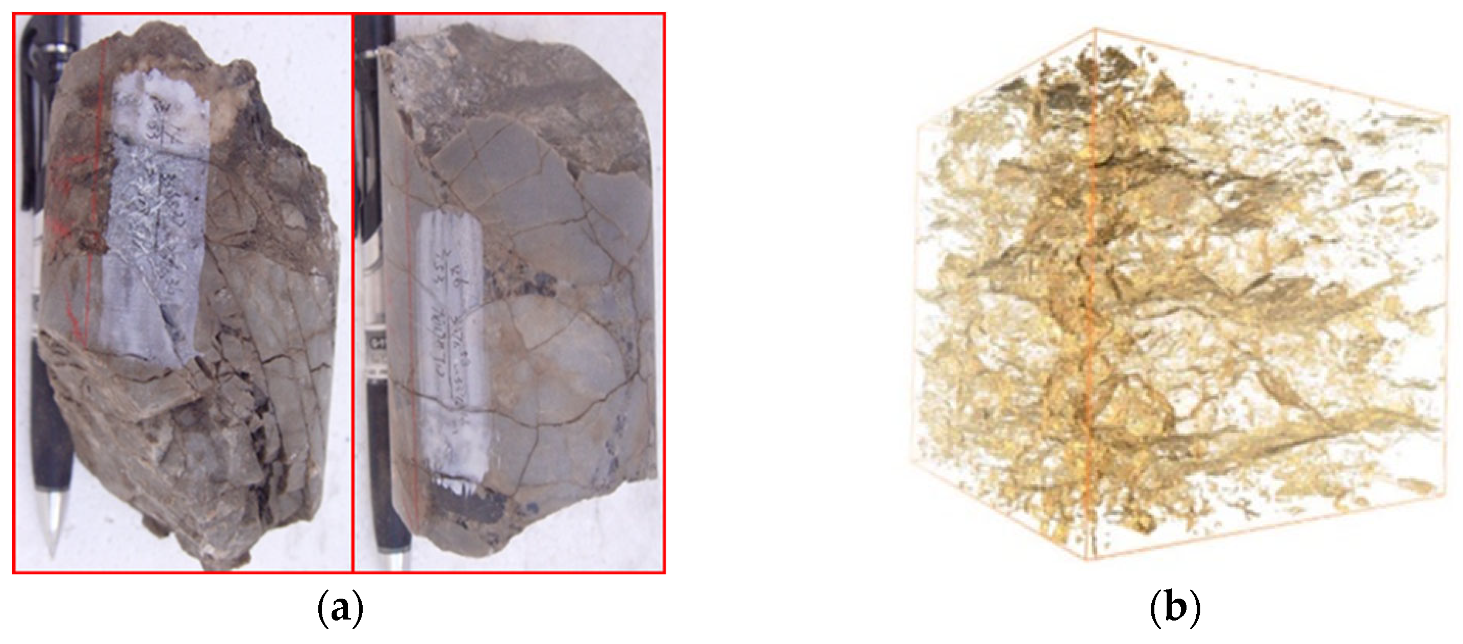
Fracture media can also be commonly found in oil, gas and geothermal reservoirs (
Figure 2). It contributes much more permeability and conductivity than normal porous media [
27]. Nowadays, naturally fractured oil, gas and geothermal reservoirs in deeper, tighter and more complex conditions have turned into one hotspot for underground energy exploration and exploitation [
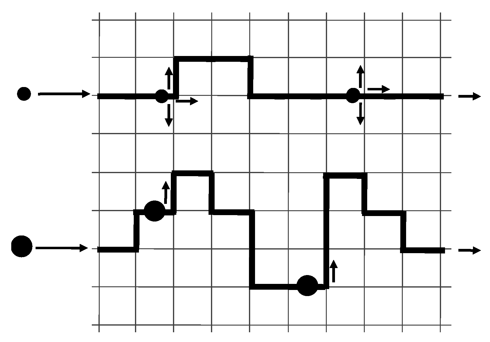
28]. Naturally fractured reservoirs have an extensive distribution in worldwide, including the Middle East, North America and Central Asia. Sichuan and Tarim basins in China have large areas of naturally fractured reservoir distribution. The widely distributed natural fractures and low-permeability matrix are the most prominent characteristics of naturally fractured tight reservoirs. Developed natural fractures are of great importance for high-efficiency reservoir exploitation. However, they can also result in the invasion of drilling fluid which is one kind of particulate suspension (
Figure 1). Severe permeability damage and subsequent productivity decline have been observed in this kind of reservoir because of granule retention and subsequent fracture clogging [
29]. Moreover, Granules in the suspension are essentially distributed in size. However, most of the research focuses only on the mono-sized suspended granule flow and retention behaviors in porous media. Stochastic modeling for multi-sized suspended granule flow and retention in naturally fractured reservoirs remains not available in the literature.
In the process of suspended granule transport, granule retention can lead to great variations in the fracture media properties, including fracture density distribution, porosity and permeability. On the other hand, the changes in the properties of fracture media can influence the transport and retention behaviors of suspended granules [
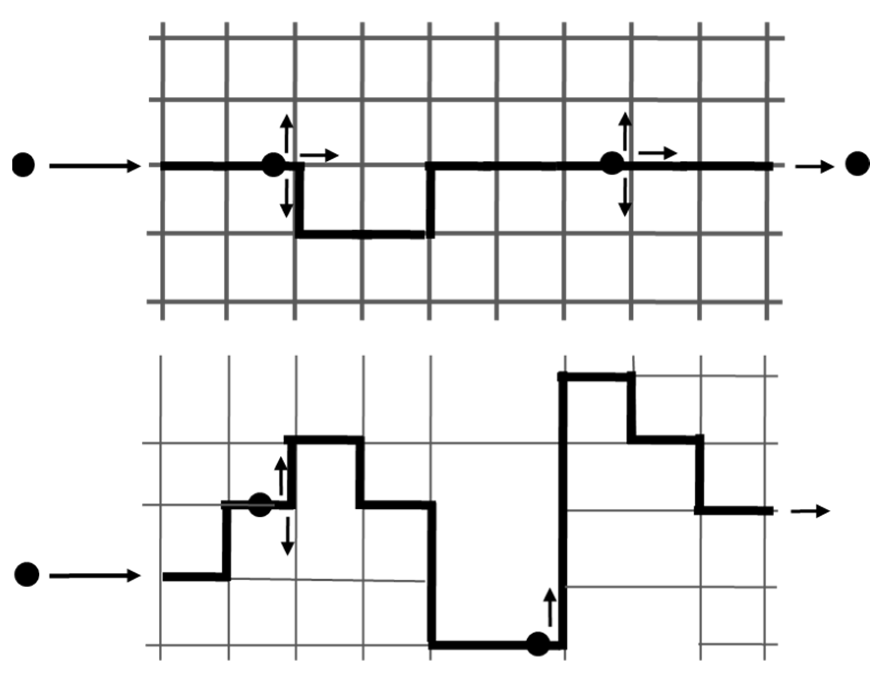
30]. Therefore, the evolution of fracture network connectivity with granule retention is of great importance for suspended granule transport modeling in fracture media. Percolation theory belongs to the probability theory used to predict the properties of random media, which usually has an association with network modeling [
31]. It has a great advantage in the prediction of medium properties variation caused by granule retention [
32]. However, few studies have given an introduction of the percolation model to the modeling of suspension flow and granule retention behaviors in fracture media. To our best knowledge, the behaviors of suspended granule flow and retention in fracture media remain not well understood and quantified.
The current work develops novel stochastic models for multi-sized suspended granule flow and retention in naturally fractured reservoirs. Percolation theory is introduced to develop the fracture network accounting for the connectivity evolution with granule retention and fracture clogging. Granule retention and fracture clogging dynamics equations are proposed considering incomplete fracture clogging by retained granules. The microscale model is allowable to be upscaled and a numerical solution is obtained for the macroscale model system for the prediction and control of permeability damage related to the multi-sized granule transport in fracture network. Laboratory experiments on granule transport in fracture media are performed to validate the proposed model.
The structure of the current paper is as follows.
Section 2 derives the governing equations for suspended granule flow and retention in the fractured reservoir, including the models of percolation fracture network, granule retention kinetics and fracture clogging kinetics. The model system is then upscaled and numerically solved for multi-sized granule flow and retention in fracture media.
Section 3 presents the sensitivity analysis for the suspended and retained granule concentration profiles, and the fracture network properties evolution (e.g., permeability and fracture density distribution) during suspended granule transport.
Section 4 presents the laboratory materials, setup, methodology and model validation by the experimental results. Conclusions of
Section 5 finalize the current work.
3. Quantitative Analysis of the Solution
In this section, a quantitative analysis of the modeling solution is conducted. The fracture distribution data is adopted from the fractured reservoir in Sichuan Basin, China. It shows that the initial aperture and length of fractures exhibit a normal distribution. The mean value and standard deviation for fracture aperture are 0.525 mm and 0.1 mm, respectively (
Figure 4a). Because of its developed natural fractures and ultra-low matrix permeability, the fractured tight reservoir is regarded as fracture media. Multi-sized suspended granule is injected into the medium with granule diameter of 0.3 mm, 0.4 mm, 0.45 mm, 0.5 mm and 0.55 mm. According to the model proposed in the second section, the concentration distribution of capture granules and the evolution process of fracture medium properties are calculated and analyzed in detail.
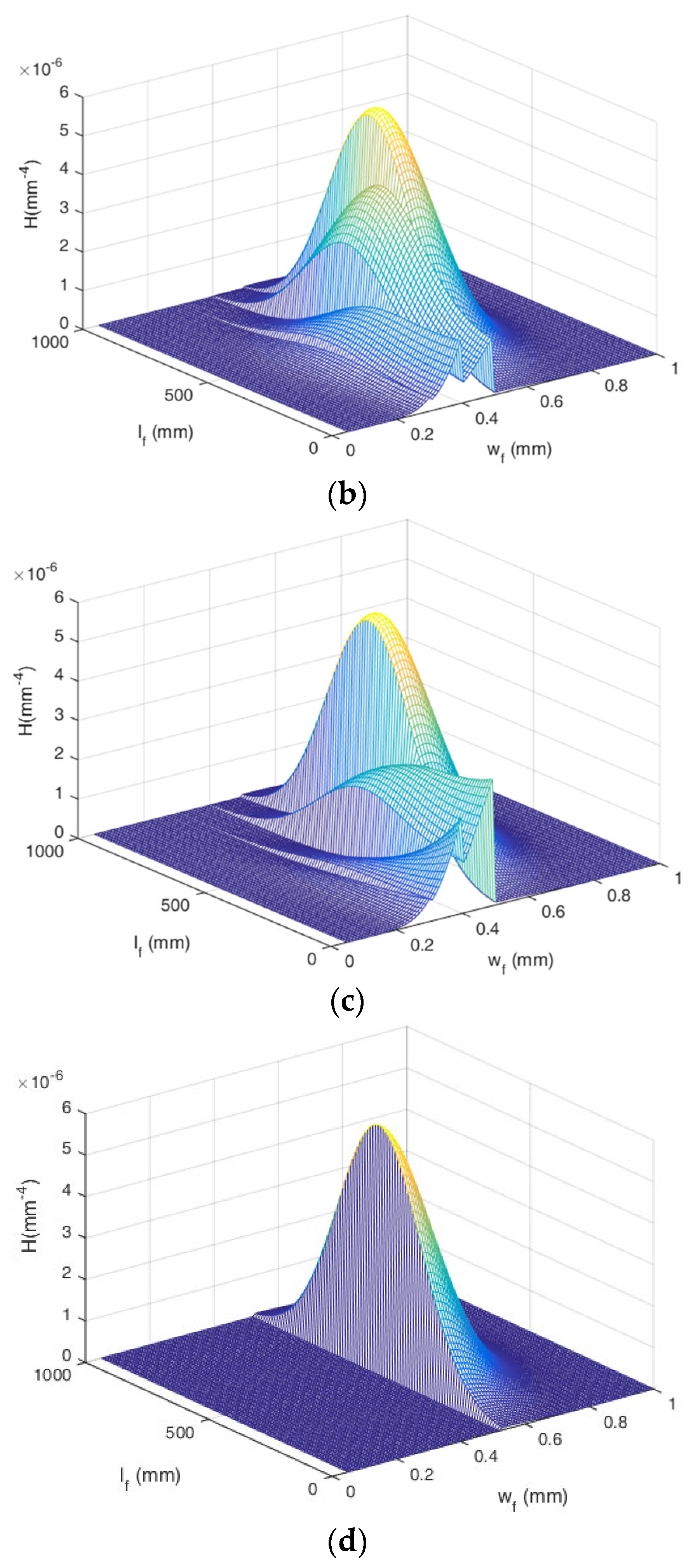
Figure 4 shows the variation of fracture density distribution because of granule retention and fracture clogging during suspended granule flow in the fracture network. Fractures of aperture smaller than the granule size (
af <
ds) are plugged during granules capture. The concentration distributions of fractures with smaller aperture decline gradually with granules injection due to fracture clogging by retained granules (
Figure 4b,c). For the fractures with the same aperture, the concentration distribution for shorter fractures increases gradually because the longer fractures are plugged into shorter ones during granules capture. With the continuous granule capture within fractures, the fracture length becomes shorter and shorter and the finally vanish. For the fractures with an aperture greater than the granule diameter, no granule retention occurs within them, and their density distribution keeps constant (
Figure 4d). The reason is that size exclusion is the fundamental granule retention mechanism considered in this work.
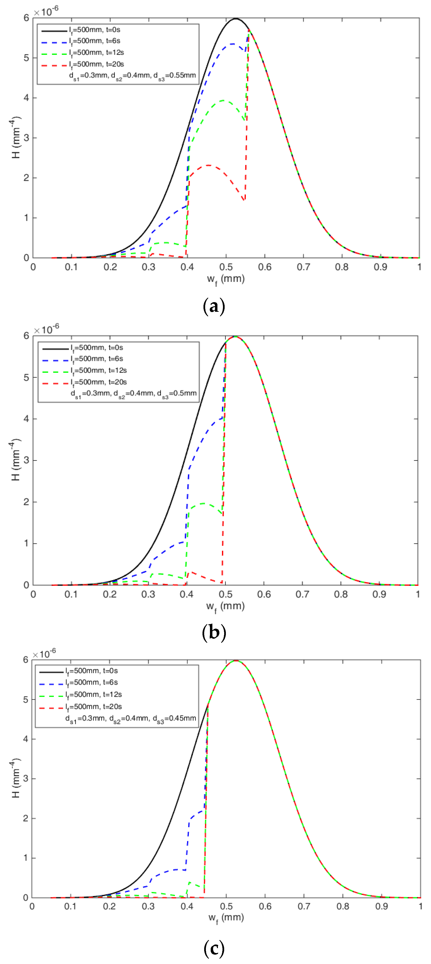
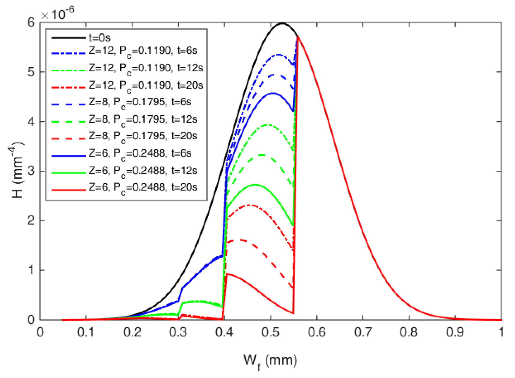
Figure 5 presents the density distribution evolution of the fractures with the same length during multi-sized granules transport in the fracture network. The modeling results show that fracture density distribution declines with time for fractures with aperture
af less than the granule diameter
ds because of granule size exclusion; while
T remains constant for fractures of aperture greater than the maximum granule diameter (
af >
dsmax). The results indicate that greater fractures (
af >
dsmax) remain accessible to the granules all the time.
The fractures whose apertures are equal to the granule size decline faster than those with size smaller than the granule size. The reason is that fracture with greater aperture is characterized by larger suspension flux, which results in higher granule retention rate. Higher retention rate leads to faster decline of fracture density. For different granule diameters in
Figure 5, greater granule diameter leads to larger fracture density decrease, which further negatively affects the fracture network conductivity and permeability. Therefore, the fracture clogging effect can be controlled by the rational optimization of granule diameter in the colloidal suspension.
The evolution of retained granule concentration and fractured network permeability during the retention of multi-sized granules of 0.3 mm, 0.4 mm and 0.5 mm diameters are shown in
Figure 6 and
Figure 7.
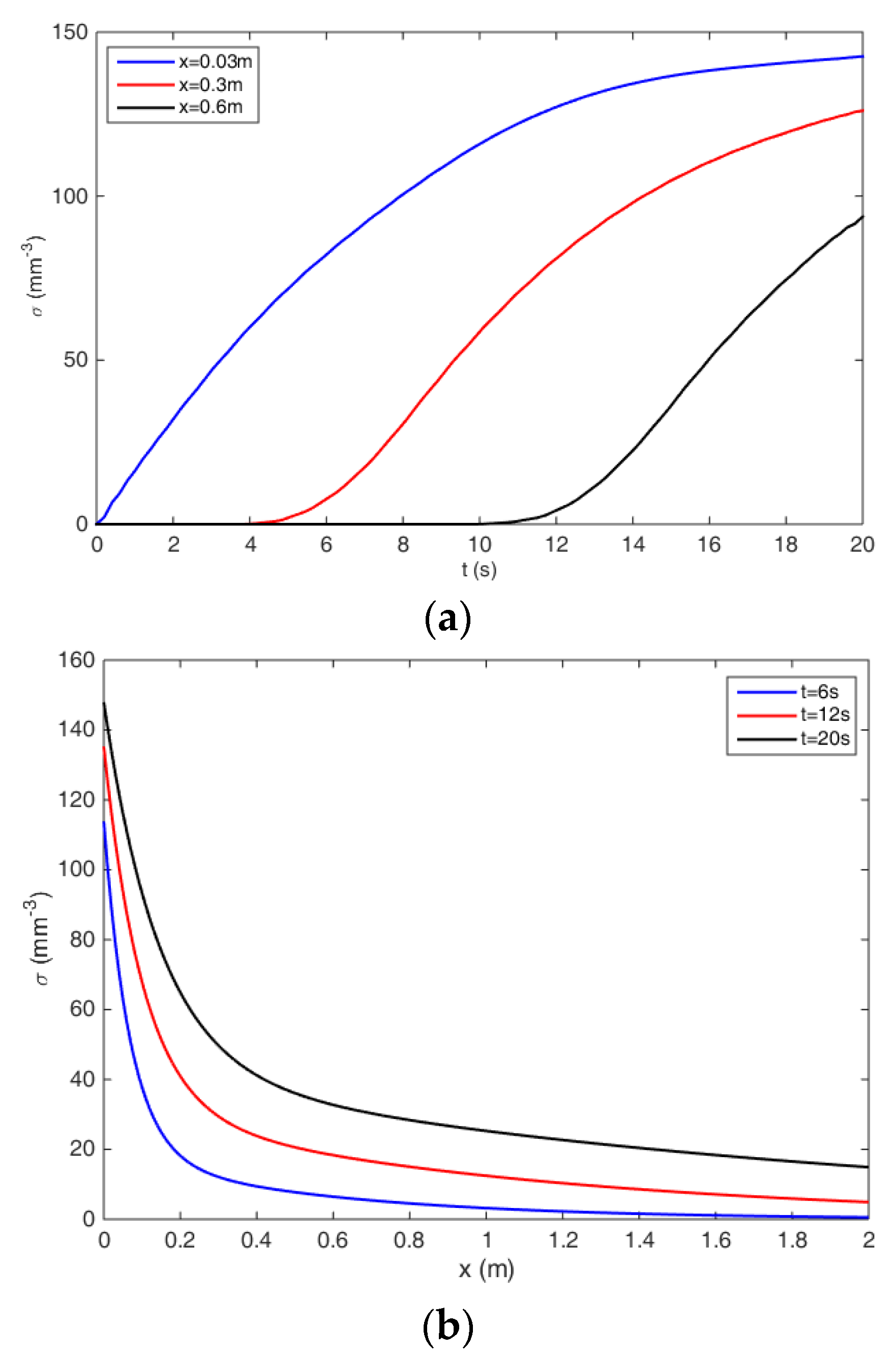
Figure 6 shows the evolution of retained granule concentration profiles for multi-sized granules. Modeling results in
Figure 6a,b indicate that the retained granule concentration raises with time and declines with distance in non-linear form.
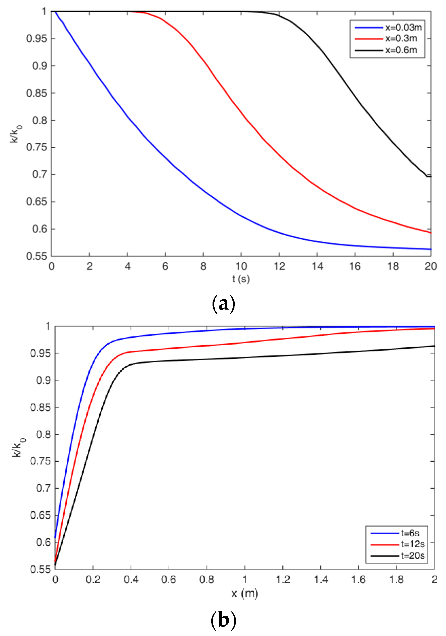
Figure 7 shows the variation of fractured network permeability with time and distance for multi-sized granules. Because of granule retention and resultant fracture clogging, the conductivity and dimensionless permeability of the fracture network decreases in a non-linear form (
Figure 7a). Moreover, the permeability declines more quickly than the permeability far away from the inlet (
Figure 7b). The reason is that the retained granule concentration is larger in the near-inlet region based on the retention concentration results in
Figure 6.
Figure 8 compares the retained granule concentration between mono-sized and multi-sized granules during suspended granule transport. For the mono-sized granule, larger granule diameter results in larger retained granule concentrations in the near inlet area (
Figure 8a). It is because the path tortuosity is much higher for larger granules to pass through the fractured network, which leads to higher capture probability and capture rate for larger granules (
Figure 9). However, lower retained granule concentration in the near-inlet region often corresponds to greater granule invasion depth due to the lower fracture clogging by retained granules (
Figure 8b). Therefore, the retained granule concentration in the near and far inlet region cannot be adjusted simultaneously for the mono-sized granules. For the multi-sized granules, the retained granule concentration in the inlet region and the granule invasion depth can be controlled effectively at the same time according to the rational optimization of granule size combination and their concentrations (
Figure 8b).
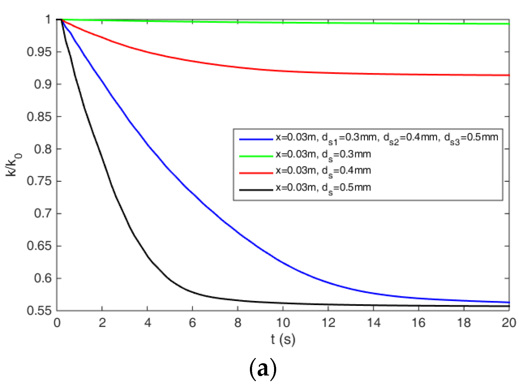
Figure 8 compares
k/k0 between mono-sized and multi-sized granules during suspended granule transport. For the mono-sized granule, higher granule size results in lower dimensionless absolute permeability in the near inlet area due to the higher retained granule concentration and fracture clogging effect (
Figure 8a and a). However, the permeability decline range is much wider for smaller granule than that of the larger granules (
Figure 10b). The permeability decline rate and range cannot be controlled at the same time due to the retained granule concentration profile for the mono-sized granules. However, for the multi-sized granules, the permeability decline rate and range can be controlled effectively and simultaneously by the rational optimization of granule size combination and their concentrations (
Figure 10b).
Three key granule sizes are often used to represent the granule size distribution of suspended granules, including D90, D50 and D10. D90 represents the value in which 90% of the granule size in the suspended granule is less than and the same as D50 and D10. Three-sized granules are used to analyze the effect of D90, D50 and D10 on the profile of dimensionless absolute permeability during suspended granule transport (
Figure 11). D90 value mainly affects the permeability decline degree in the near inlet area as well as the permeability decline range (
Figure 11a). A higher D90 value leads to a larger permeability decline in the inlet area and a smaller permeability decline range. D50 value mainly affects the average permeability decline degree along the radial distance but has little impact on the permeability decline range (
Figure 11b). Higher D50 value results in a larger average permeability decline degree. D10 value slightly affects the permeability decline profile (
Figure 11c). However, the D10 value can be used to adjust the D90 and D50 values of the suspended granule.
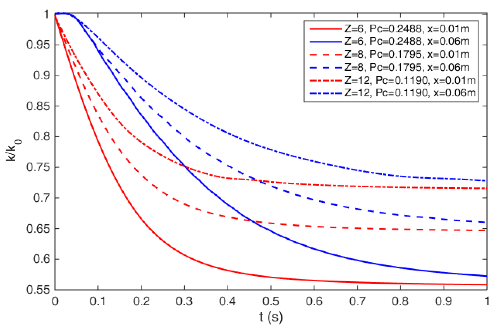
The parameters which characterize the fracture network connectivity mainly include coordination number
Z and percolation threshold
pc. Their impacts on the flow and retention behaviors of multi-sized suspended granule are presented in
Figure 12,
Figure 13,
Figure 14 and
Figure 15. Larger
Z and smaller
pc improve the connectivity of the fracture network.
Figure 12 presents the variation of retained granule concentration for multi-sized granules capture in fracture network with different connectivity. Retained granule concentration declines with the network connectivity increase. The reason is that lower fracture network connectivity yields higher granule path tortuosity, which leads to higher probability for the granules to come into the smaller aperture fractures (
af <
ds) and be retained (
Figure 13). Therefore, a higher fracture network connectivity also results in lower decline of fracture permeability as well as fracture density because of lesser retained granule concentration during the transport of multi-sized suspended granule (
Figure 14 and
Figure 15).
4. Laboratory Experiments
In this part, laboratory experiments of suspension transport and granule retention are carried out. Retained granule concentration, pressure drop and permeability changes during suspended granule flow in fracture media are measured and compared with above modeling results for model validation.
4.1. Experimental Design
Fractured core sample is adopted as the fracture media for suspended granule flow and retention experiments in this paper. The diameter and length for the fractured core sample is 25 mm and 60 mm, respectively. The core sample is obtained by coring operation in the fractured tight reservoirs of Sichuan Basin, China. Compared with fracture permeability, the matrix permeability is lower than 0.01 mD, which can be neglected. Therefore, the flow rate of fluid through pores is negligible compared with the fracture. The fracture aperture distribution of the core sample is determined by three-dimensional laser scanner. The fractured surface morphology images of the fractured core sample obtained from the three-dimensional laser scanner are shown in
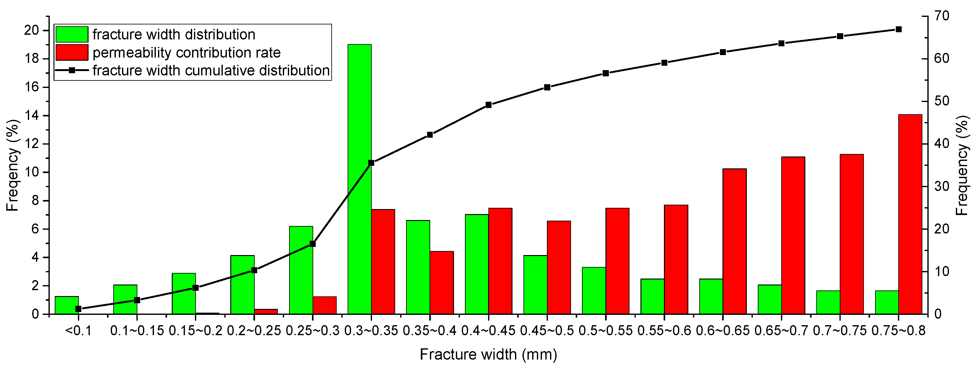
Figure 16. Fracture aperture distribution density can be determined according to the fracture surface contour images and presented in
Figure 17. The contribution rate of fracture permeability and its cumulative distribution in
Figure 17 are obtained based on the distribution density of fracture aperture. As shown in
Figure 17, when the fracture aperture is 0.7 to 0.8 mm, the maximum contribution rate appears.
Since the repulsion criteria of granule/grain and granule/granule are used in these experiments, no granules can be attached and retained on the fracture surface. Under this condition, we can conclude that size exclusion is the only mechanism of granule retention in the experiment. This conclusion is consistent with the model hypothesis. With regard to a specific granule material and fracture medium, the repulsion condition is realized according to the adjustment of fluid properties, including pH value as well as salinity value [
11]. Zero salinity of water, alkalinity of suspension with pH ≈ 11 and granules covered by carboxyl functional groups can result in size exclusion as the only mechanism of granule retention. These criteria are adopted in the granule suspension flow and granule retention experiments in the current paper.
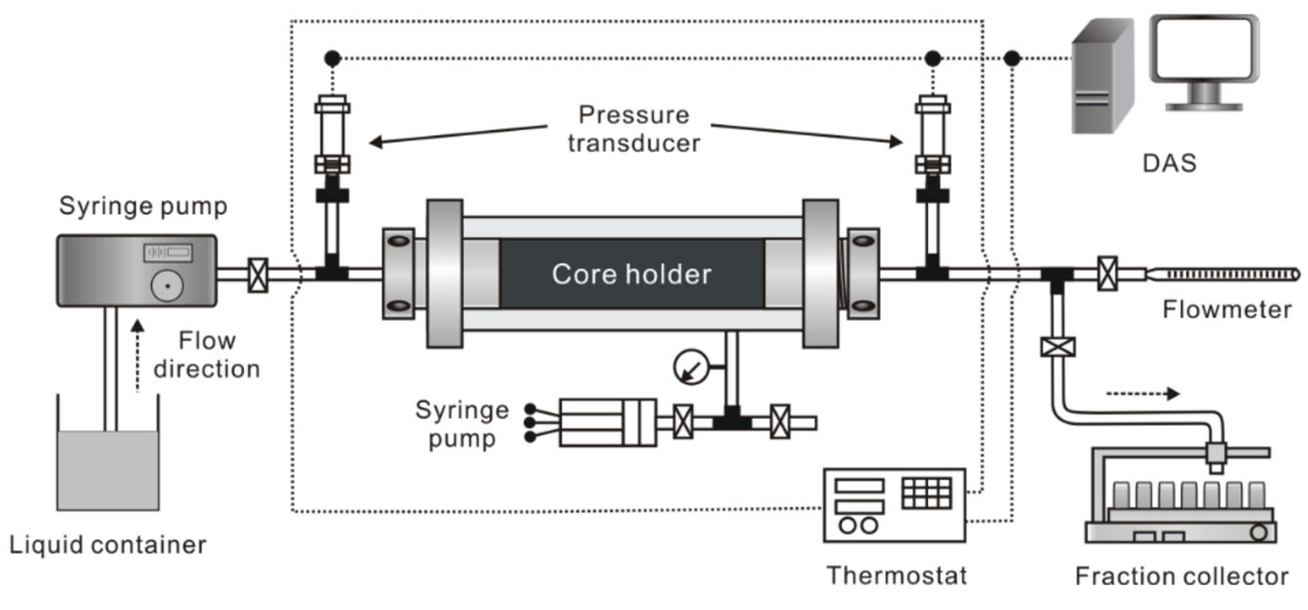
As is shown in
Figure 18, we can have an observation about the application of the experimental apparatus in the suspended granule flow and retention experiments. ISCO pump is used to inject granules in suspension through the fractured core sample at a constant rate. Another pump provides confining pressure to the core sample holder. A fraction collector is connected in parallel with a flowmeter. They are used for the constant collection of the outlet flux and measure the output flux. Two pressure sensors are adopted to monitor the pressure at both ends of the core sample, respectively. The outlet pressure is constant and equal to atmospheric pressure. All the pressure values are recorded in real time by a data acquisition system (DAS). All the setup is put in a thermotank in order to keep constant 25 °C. Before we carry out the suspension transport experiments, alcohol, soapy water and deionized water are used to clean all the flow elements of the experimental system so that the effect of residual contaminants can be avoided.
Calcium carbonates are adopted as suspended granules in this work. With the help of the prepared solution, the fractured core sample is saturated in a vacuum condition for 48 h. On this basis, suspensions with granule sizes of 0.3 mm, 0.5 mm and 0.7 mm are, respectively injected into the fractured sample at the same volume flow rate. Mono-sized and multi-sized granules are injected for comparison with the same overall concentration. With regard to each case, outlet flow rate is regularly measured by means of the flow meter. The pressure sensor is used to record the inlet and outlet pressures in real time. After each test, retained granules in the fracture were collected for every 5 mm section to obtain the spatial distribution of retained granule concentration. Retained granules are sieved to calculate the granule number of each size. During the whole experiment, Darcy’s law is used to calculate the permeability changes caused by granule retention and resultant fracture clogging.
4.2. Experimental Results and Discussion
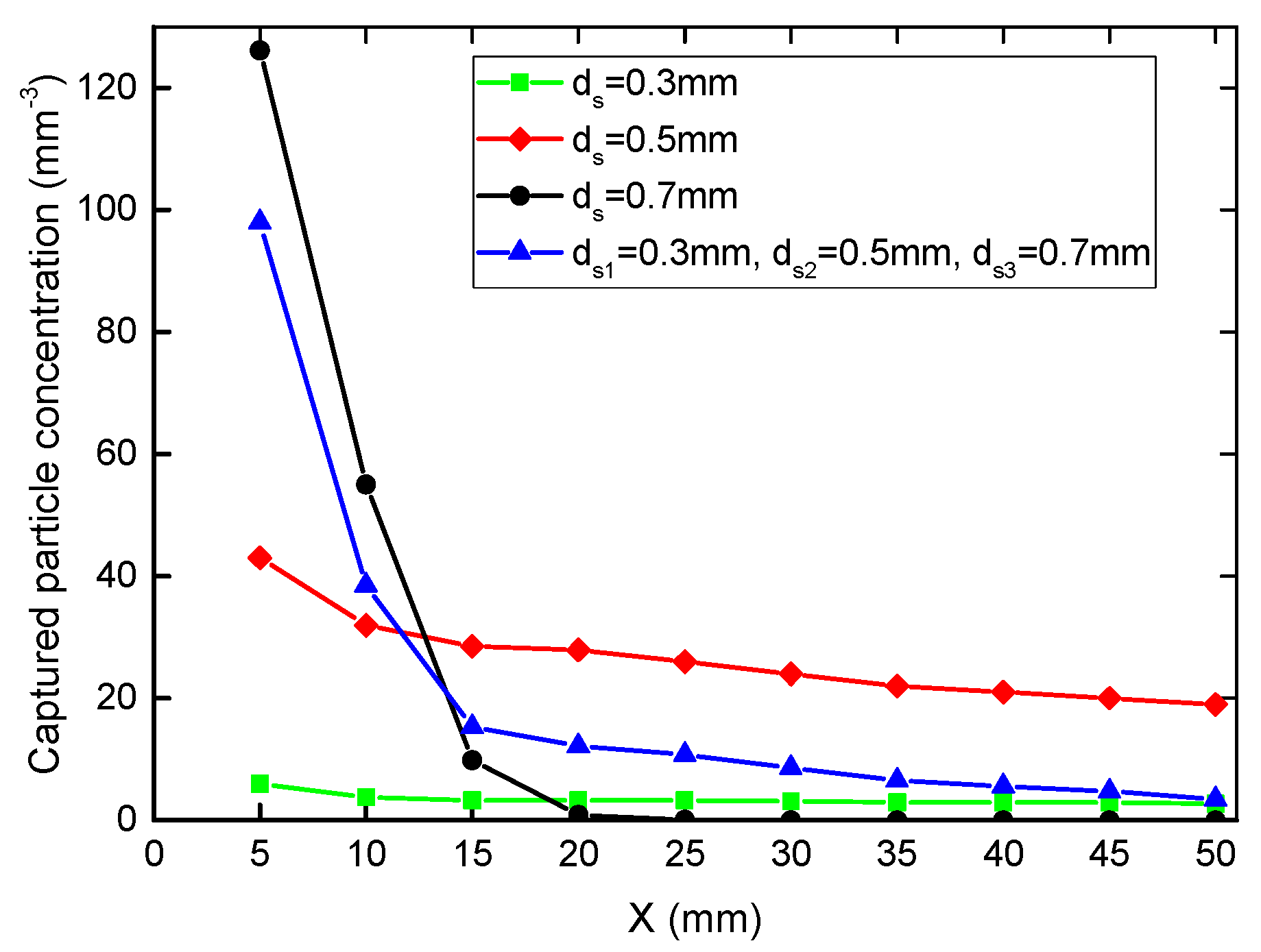
Figure 19 shows spatial concentration distribution of retained granule for mono-sized and multi-sized granule with the same injected granules concentration. For the mono-sized granules, the 0.7 mm granule corresponds to the highest retained granule concentration during the core inlet region and the lowest granule invasion depth. For the multi-sized granules, the spatial concentration distribution of retained granules fall in between the distribution of mono-sized granules. Laboratory experiments results in
Figure 19 indicate the same trend of retained granule concentration as those calculated from the proposed stochastic models (
Figure 8b).
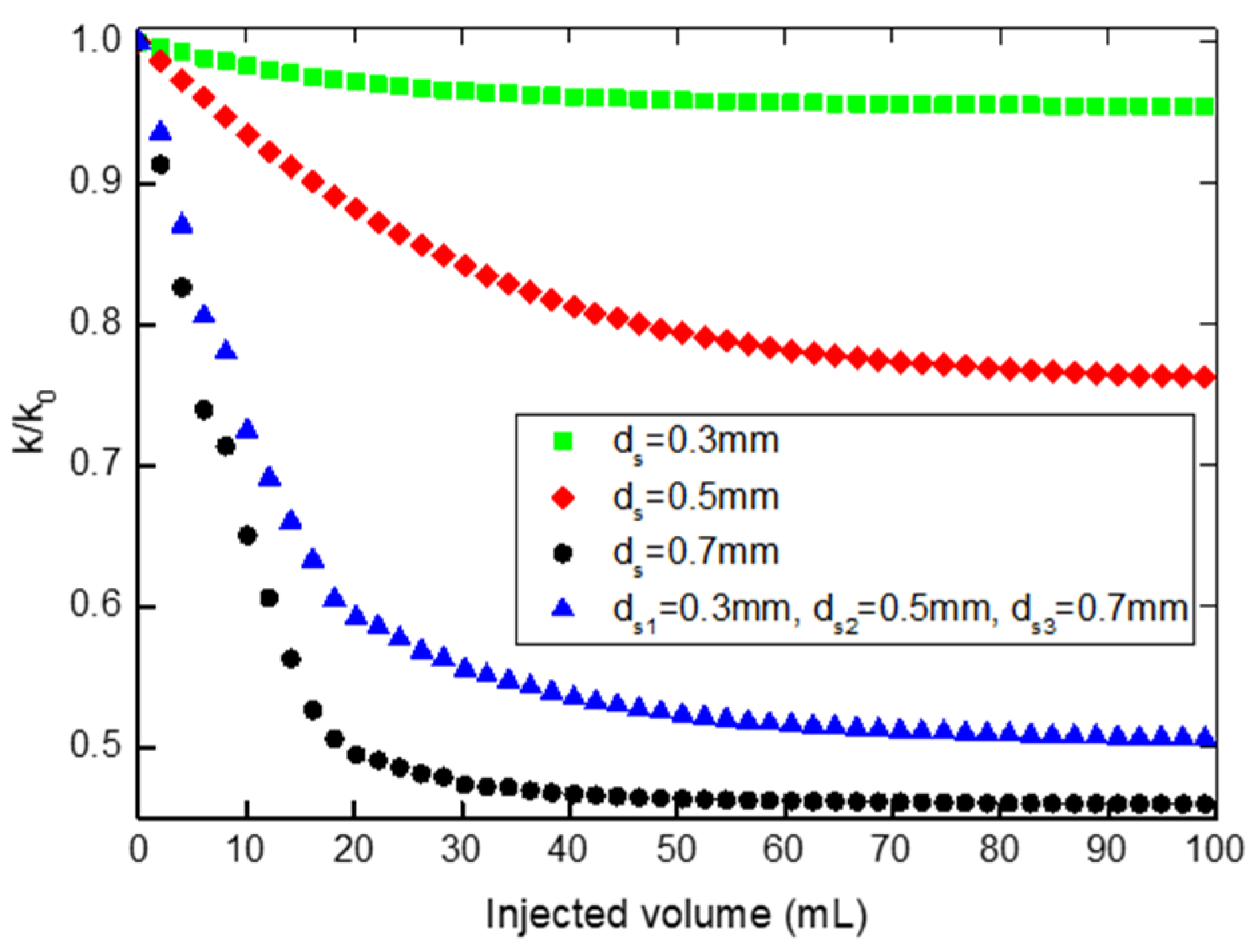
Figure 20 presents the pressure drop during injection of granule suspensions with the same granule concentration but different granule sizes. The pressure differential is a reflection of fracture clogging which is caused by plugging capture by size exclusion. The pressure drop for injected granule size in the descending order is 0.7 mm, multi-sized granule combination (0.7 mm, 0.5 mm and 0.3 mm), 0.5 mm and 0.3 mm. Corresponding to the pressure drop, the
k/k0 evolutions during the transport of suspended granules with the same concentration but different granule sizes are shown in
Figure 20. Dimensionless permeability
k/k0 decline indicates the fracture clogging by retained granules. The dimensionless permeability decline for injected granule size in the descending order is also 0.7 mm, multi-sized granule combination (0.7 mm, 0.5 mm and 0.3 mm), 0.5 mm and 0.3 mm. For mono-sized granules, laboratory results show that 0.7 mm granules can achieve the most efficient plugging of the fractures with maximum permeability contribution rate (0.7–0.8 mm). The dimensionless permeability for multi-sized granules falls in between that of mono-sized granules. The laboratory experiment results in
Figure 20 indicate that the decreasing trend of
k/k0 is consistent with the results of the proposed model results in
Figure 10a.
Another important finding from the model results is that fractures with apertures close to the injected granule diameter vanish more quickly. In addition, when the fracture aperture is equal to the injected granule diameter, the fracture disappears fastest. Fracture clogging with the largest contribution rate of permeability results in larger declines of
k/k0. The fracture with an aperture of 0.7~0.8 mm makes the largest contribution. From the experimental results in
Figure 20, we can see that the dimensionless permeability for 0.7 mm granules decline the most compared with those of 0.5 mm and 0.3 m granules during suspended granule injection. These results indicate that fractures with the largest contribution rate are plugged faster by 0.7 mm granules than the 0.5 mm and 0.3 mm granules. Therefore, the laboratory experiment results indicate that the fractures with an aperture (0.7~0.8) mm close to the injected granule diameter (0.7 mm) disappear more quickly. The results are in good agreement with the model solution and verify the developed model qualitatively.
Because of the lack of fracture length distribution data, the model proposed in the current paper has only been qualitatively verified. In order to realize the quantitative verification of the proposed model, the data set of fracture size density distribution should be determined through seismic response. Moreover, for suspension transport with higher particle concentration, particle bridging can occur and become another particle capture mechanism. In this case, size exclusion is not the only particle capture mechanism. It will be investigated further in future studies. However, in this stage, the prediction of the profile and evolution of the retained granule concentration and dimensionless permeability by the proposed stochastic model is instructive enough for permeability damage control and production enhancement in fractured oil, gas and geothermal reservoirs.
5. Conclusions
Mathematical and laboratory modeling of multi-sized suspended granule transport in naturally fractured reservoir accounting for granule retention and fracture clogging kinetics allows drawing the following conclusions:
Percolation theory is introduced to develop the fracture network model accounting for the connectivity evolution with the granule retention and resultant fracture clogging. Granule retention and fracture clogging dynamics equations are proposed considering the behavior of incomplete fracture clogging by retained granules. The micro-scale stochastic model allows for upscaling and the numerical solution is obtained for the macro-scale model system for the prediction of the multi-sized granule transport behavior in the fracture network.
During suspended granule flow and retention in the percolation fracture network, the granule retention and fracture clogging behaviors can be predicted quantitatively. The model solution exhibits preferential plugging of fractures with an aperture equal to or below the injected granule diameter. The fractures with an aperture equal to the granule diameter vanish fastest. The retained granule concentration and permeability damage rate decrease with the improvement of the network connectivity.
Multi-sized suspended granules show great advantages over mono-sized suspended granules in the control of granule retention and fracture clogging effect. Based on the rational optimization of granule size combination and concentration, the profiles for granule invasion and permeability decline can be controlled effectively and simultaneously. The proposed model shows good agreement with laboratory data.


 ,
, 