
Experimental Study on HMCVT Adaptive Control of Cotton Pickers

 ,
,
Abstract
:1. Introduction
2. Materials and Methods
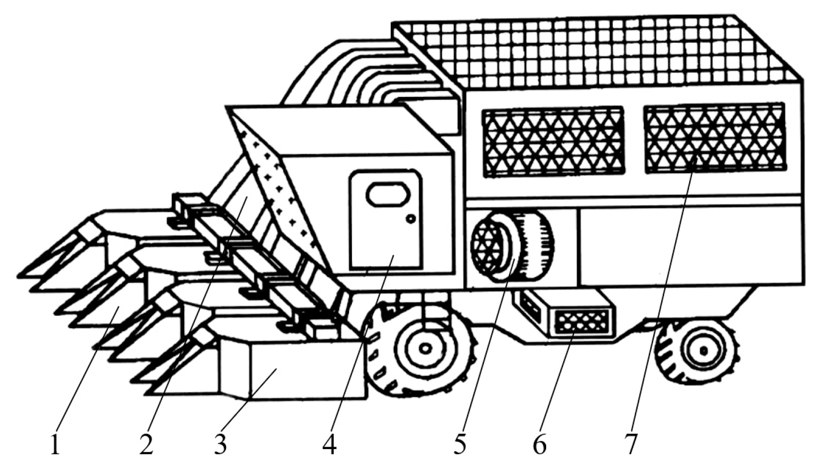
2.1. Composition and Transmission Requirements of the Cotton Picker
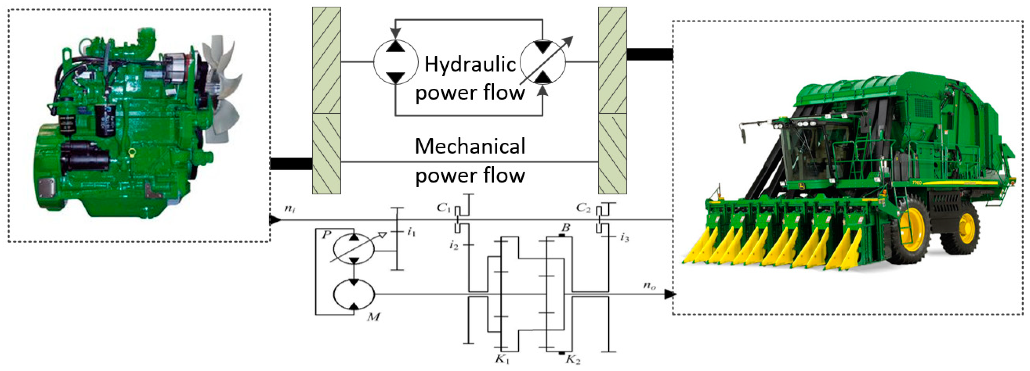
2.2. Transmission System Structure
2.3. Analysis of HMCVT Dynamics
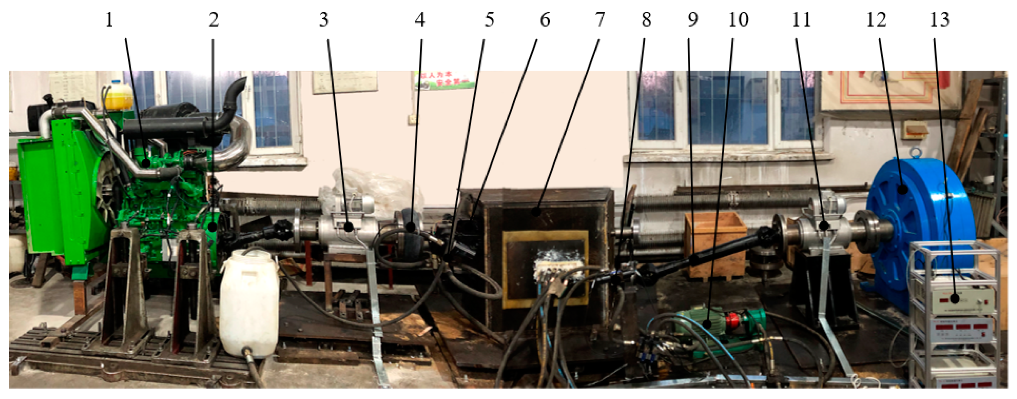
2.4. Test Bed Structure
2.5. Design of HMCVT Measurement and Control System
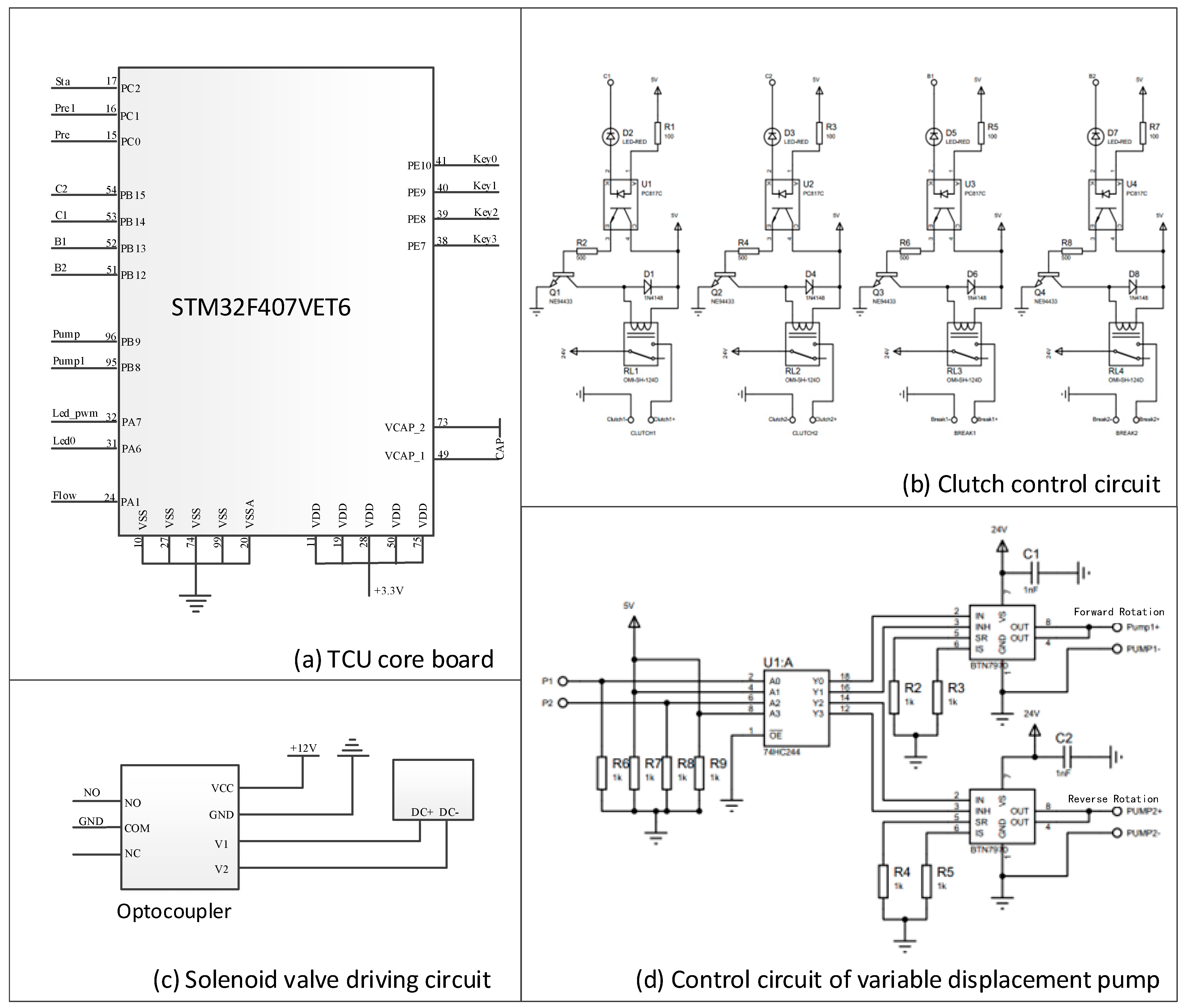
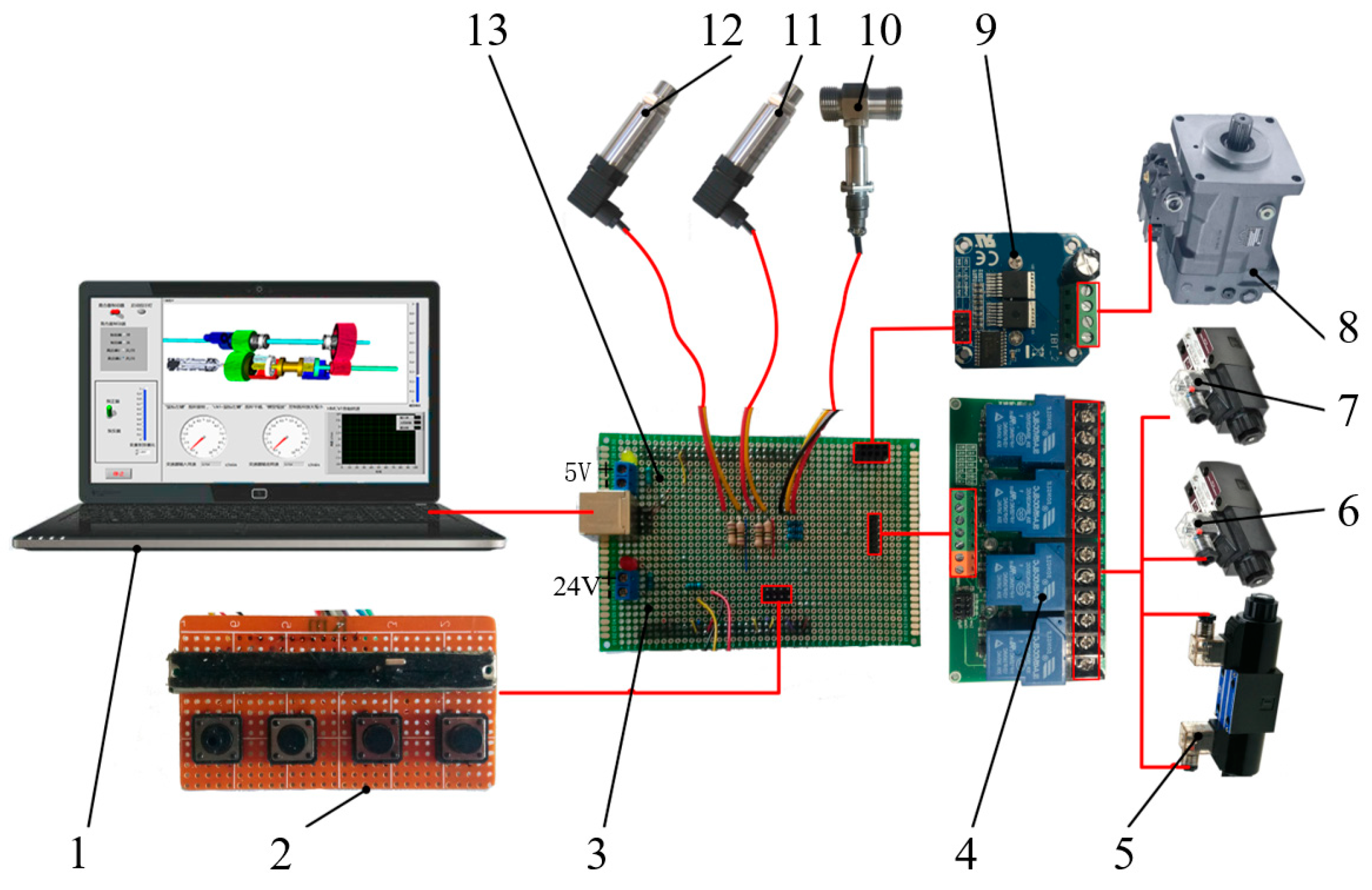
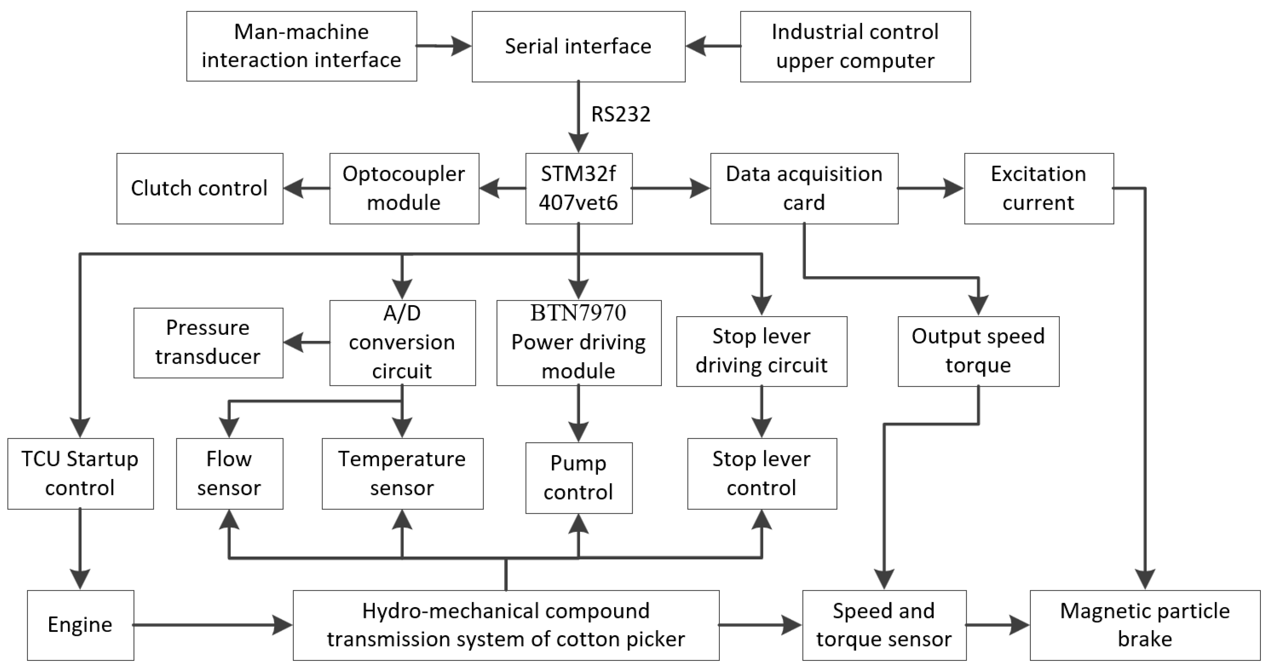
2.5.1. Hardware Design of Measurement and Control System
- (1)
- Hardware composition
- (2)
- Sensor configuration
- (3)
- Control Circuit Design
2.5.2. Software Design of HMCVT Measurement and Control System
- (1)
- Composition of measurement and control software
- (2)
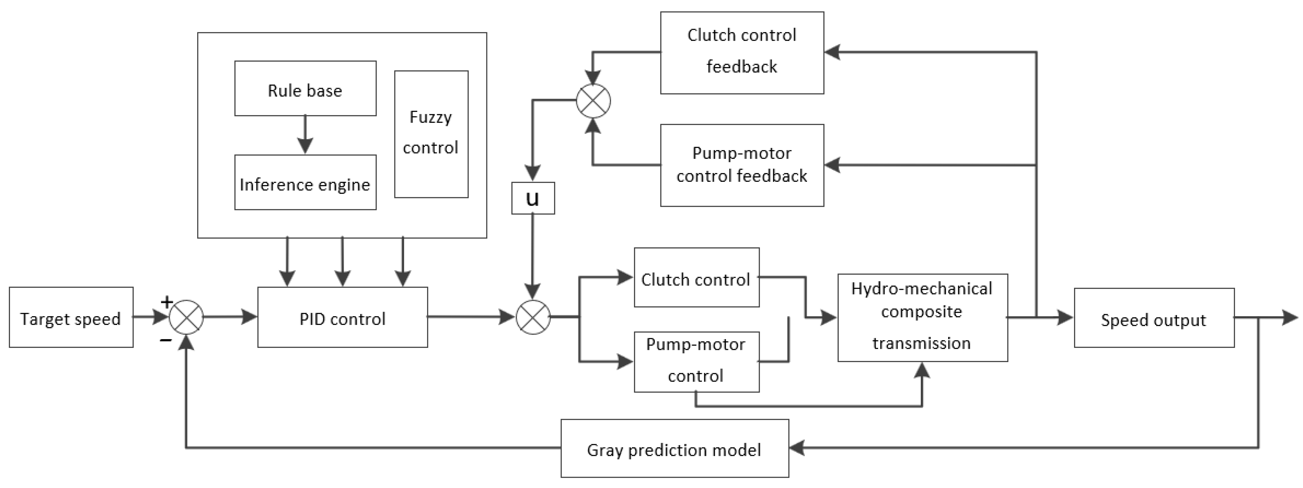
- Control strategy
3. Test Results and Analysis
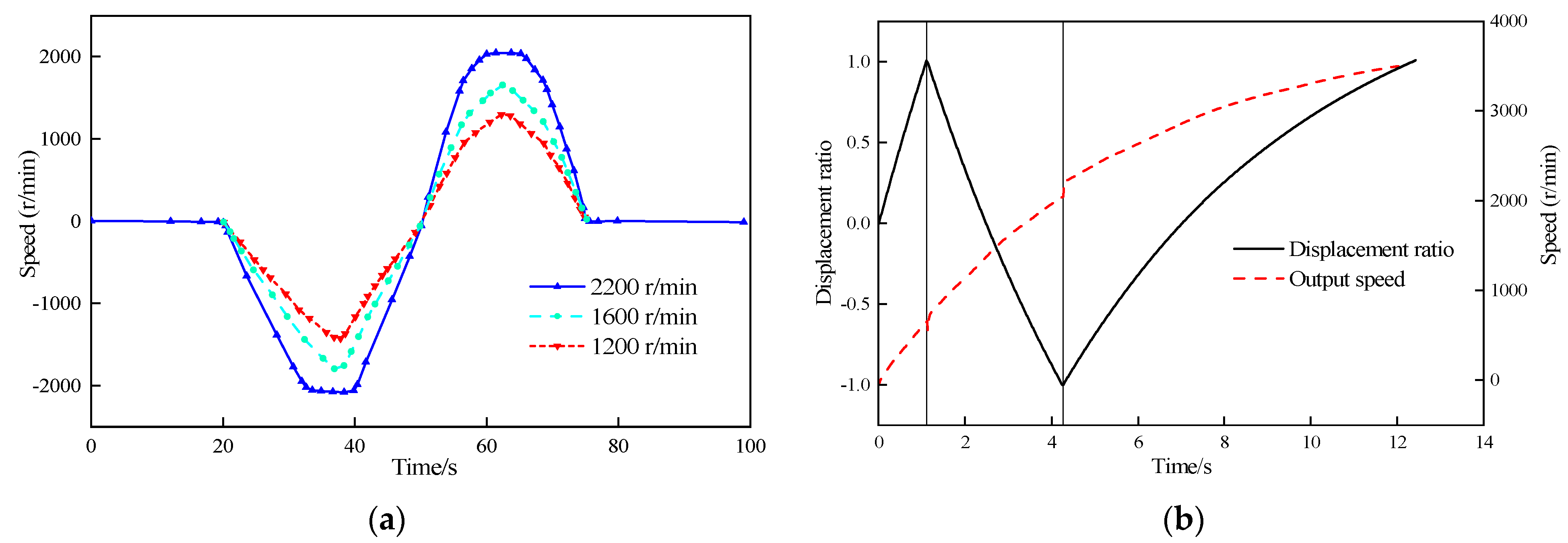
3.1. Continuity Testing
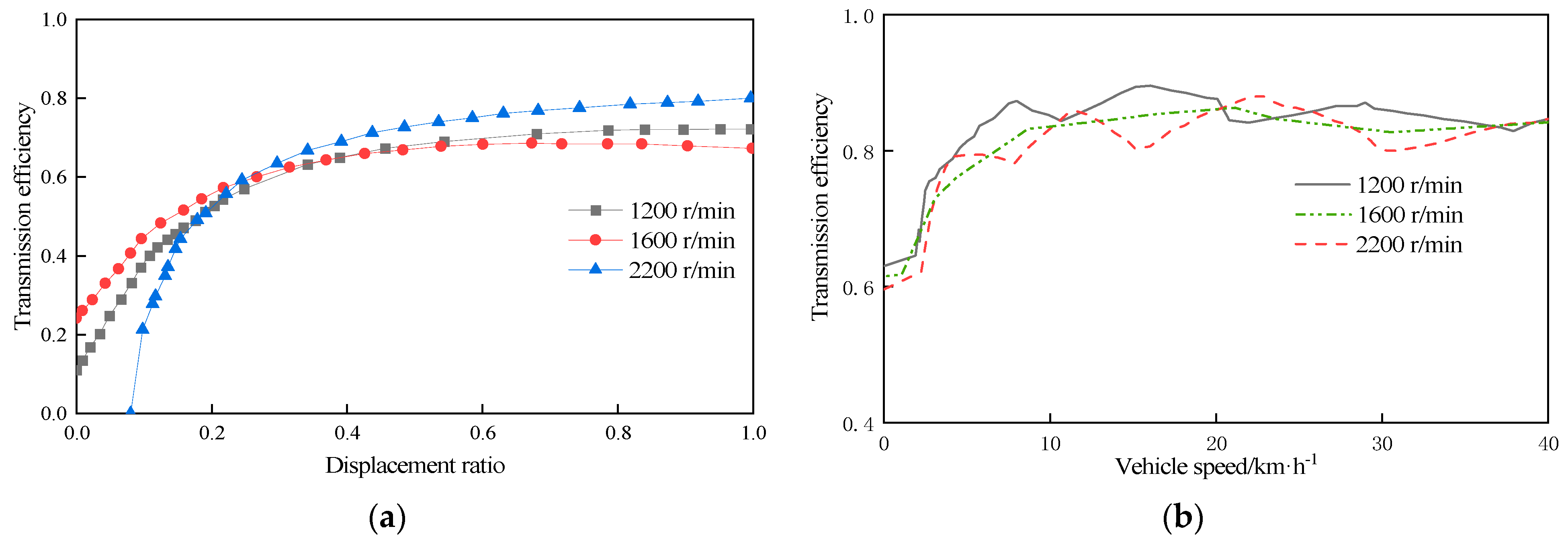
3.2. Transmission Efficiency Test
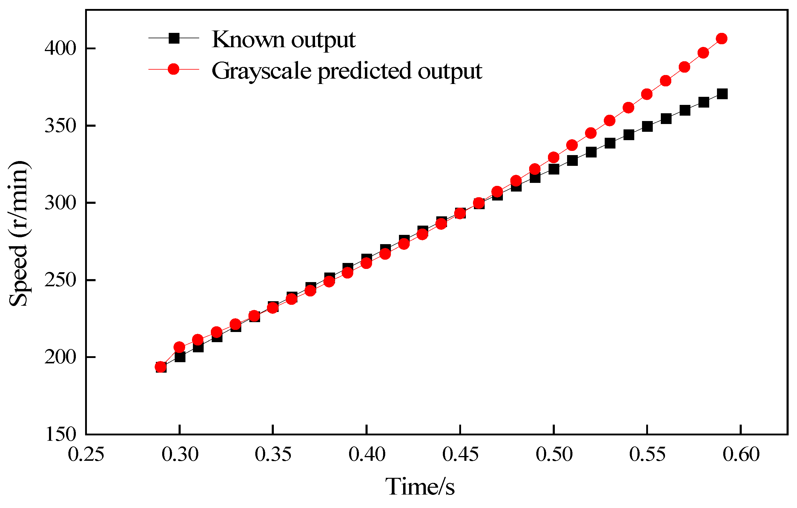
3.3. Adaptive Testing
4. Discussion
5. Conclusions
- (1)
- As the input speed increases, the peak time of the pump motor output speed is prolonged, while the overall speed regulation process is smoother and the output speed process of the HMCVT system is continuous.
- (2)
- As the displacement ratio of the variable pump increases, the transmission efficiency of the hydraulic system increases accordingly, but the highest efficiency is around 0.8. At a working speed of 10 km/h, the cotton picker’s HMCVT system transmission efficiency is more than 80%. The mechanical system’s high efficiency makes up for the lower efficiency of the hydraulic system, and the cotton picker in the 15–25 km/h transmission efficiency is the highest.
- (3)
- When the picking speed of the cotton picker is set at 5.6 km/h, the speed following under the adaptive control strategy is good. Meanwhile, the output speed of the cotton picker drive system fluctuates only 0.0125% under the sudden change of external load torque, which verifies that the adaptive control has good robustness.
Author Contributions
Funding
Institutional Review Board Statement
Data Availability Statement
Acknowledgments
Conflicts of Interest
References
- Shen, S.; Wang, L. Research on China’s cotton industry security under open conditions. China Cotton 2022, 49, 1–6. [Google Scholar]
- Li, H.; Fu, X.; Wang, H.; Zhang, H.; Gu, Y.; Du, X.; Tao, Y.; Li, J. Research on the Wear Characteristics of the Hook Teeth of Cotton Pickers. Coatings 2022, 12, 762. [Google Scholar] [CrossRef]
- Zhang, R.; Chen, Y.; Zhao, D. Development status and suggestions of the cotton industry in Xinjiang. J. Smart Agric. 2023, 3, 5. [Google Scholar]
- Gu, Y.; Zhang, H.; Fu, X.; Wang, L.; Shen, Z.; Wang, J.; Song, Z.; Zhang, L. Experimental Wear Behavior Analysis of Coated Spindle Hook Teeth under Real Harvesting Work Conditions. Materials 2021, 14, 2487. [Google Scholar] [CrossRef] [PubMed]
- Wang, L.; Yin, C.; Zhang, L.; Zhang, H.; Li, H. Analysis and Experiment on the Impact of Various Hook Angle Factors on Spindle Picking Performance. Agriculture 2022, 12, 768. [Google Scholar] [CrossRef]
- Miao, Z.; Li, C.; Han, K.; Hao, F.; Han, Z.; Zeng, L. Optimal Control Algorithm and Experiment of Working Speed of Cotton-picking Machine Based on Fuzzy PID. Trans. Chin. Soc. Agric. Mach. 2013, 46, 9–14. [Google Scholar]
- Yuan, Y.; Bai, S.; Niu, K.; Zhou, L.; Zhao, B.; Wei, L.; Liu, L. Research progress in the key technologies and equipment for cotton planting mechanization. Trans. Chin. Soc. Agric. Eng. 2023, 39, 11. [Google Scholar]
- Shao, W.; Feng, J.; Zhang, F.; Wang, S.; Li, Y.; Lv, J. Aerodynamic Performance Optimization of Centrifugal Fan Blade for Air System of Self-Propelled Cotton-Picking Machine. Agriculture 2023, 13, 1579. [Google Scholar] [CrossRef]
- Wu, J.; Chen, X. Present situation, problems and countermeasures of cotton production mechanization development in Xinjiang Production and Constuction Corps. Trans. Chin. Soc. Agric. Eng. 2015, 31, 6. [Google Scholar]
- Niu, G.; Li, B.; Liu, Y.; Li, Y.; Wang, T.; Wang, S. Development and research status of cotton picker in China. J. Chin. Agric. Mech. 2020, 41, 7. [Google Scholar]
- Zhao, X.; Ni, X.; Bao, M.; Li, S.; Han, S. Coordinated Control of Picking and Walking Constant Speed of New Cotton Picker Based on AMESim-Simulink. Chin. Hydraul. Pneum. 2020, 5, 6. [Google Scholar]
- Miao, Z.; Lu, M.; Hu, X.; Zou, Z. Development and application of intelligent monitoring and controlling system of cotton-picking machine based on virtual instrument technology. Trans. Chin. Soc. Agric. Eng. 2014, 30, 35–42. [Google Scholar]
- Zhao, J.; Xiao, M.; Bartos, P.; Bohata, A. Dynamic engagement characteristics of wet clutch based on hydro-mechanical continuously variable transmission. J. Cent. South Univ. 2021, 28, 13. [Google Scholar] [CrossRef]
- Wang, G.; Zhang, X.; Zhu, S.; Zhang, H.; Ma, R.; Ti, J. Dynamic simulation on shift process of tractor hydraulic power split continuously variable transmission during acceleration. Trans. Chin. Soc. Agric. Eng. 2016, 32, 30–39. [Google Scholar]
- Yildiz, A.; Piccininni, A.; Bottiglione, F.; Carbone, G. Modeling chain continuously variable transmission for direct implementation in transmission control. Mech. Mach. Theory 2016, 105, 428–440. [Google Scholar] [CrossRef]
- Yildiz, A.; Kopmaz, O. Control-oriented modelling with experimental verification and design of the appropriate gains of a PI speed ratio controller of chain CVTs. Stroj. Vestn.-J. Mech. Eng. 2017, 63, 374–382. [Google Scholar] [CrossRef]
- Cheng, Z.; Chen, Y.; Li, W.; Liu, J.; Li, L.; Zhou, P.; Chang, W.; Lu, Z. Full Factorial Simulation Test Analysis and I-GA Based Piecewise Model Comparison for Efficiency Characteristics of Hydro Mechanical CVT. Machines 2022, 10, 358. [Google Scholar] [CrossRef]
- Cheng, Z.; Chen, Y.; Li, W.; Zhou, P.; Liu, J.; Li, L.; Chang, W.; Qian, Y. Optimization Design Based on I-GA and Simulation Test Verification of 5-Stage Hydraulic Mechanical Continuously Variable Transmission Used for Tractor. Agriculture 2022, 12, 807. [Google Scholar] [CrossRef]
- Xia, Y.; Sun, D. Characteristic analysis on a new hydro-mechanical continuously variable transmission system. Mech. Mach. Theory 2018, 126, 457–467. [Google Scholar] [CrossRef]
- Qian, Y.; Cheng, Z.; Lu, Z. Study on stepwise regression optimization of shift quality of heavy-duty tractor HMCVT based on five factors. J. Nanjing Agric. Univ. 2020, 43, 10. [Google Scholar]
- Wang, G.; Zhang, X.; Li, X.; Fan, G.; Zhang, H.; Sun, R. Analysis of shift quality of power split continuously variable transmission for tractor equipped with steel belt. Trans. Chin. Soc. Agric. Eng. 2019, 35, 11. [Google Scholar]
- Fu, S.; Yang, Z.; Du, Y.; Li, Z.; Mao, E.; Zhu, Z. Starting Control Method for Power Shift Tractor Employing Time—Varying Disturbance Rejection. Trans. Chin. Soc. Agric. Mach. 2021, 52, 371–380. [Google Scholar]
- Liu, Y.; Zhang, J.; Wan, Y.; Sun, D.; Qin, D. Adaptive Shifting Control for Data Driven Dual Clutch Transmission. Automot. Eng. 2021, 43, 9. [Google Scholar]
- Wang, G.; Song, Y.; Wang, J.; Chen, W.; Wang, J. Study on the Shifting Quality of the CVT Tractor under Hydraulic System Failure. Appl. Sci. 2020, 10, 681. [Google Scholar] [CrossRef]
- Li, X.; Zhang, L.; Yang, S.; Liu, N. Analysis and experiment of HMT stationary shift control considering the effect of oil bulk modulus. Adv. Mech. Eng. 2020, 12, 727–739. [Google Scholar] [CrossRef]
- Cheng, Z.; Lu, Z. System response modeling of HMCVT for tractors and the comparative research on system identification methods. Comput. Electron. Agric. 2022, 202, 11. [Google Scholar] [CrossRef]
- Cheng, Z.; Lu, Z.; Qian, J. A new non-geometric transmission parameter optimization design method for HMCVT based on improved GA and maximum transmission efficiency. Comput. Electron. Agric. 2019, 167, 9. [Google Scholar] [CrossRef]
- Wang, Q. Design and Study on Control Strategy of Cotton-Picking Machine Hydro-Mechanical CVT. Master′s Thesis, Shihezi University, Shihezi, China, 2019. [Google Scholar]
- Zhao, X. Design and Research on Control System of Hydro-Mechanical Continuously Variable Transmission for Cotton Picker. Master′s Thesis, Shihezi University, Shihezi, China, 2021. [Google Scholar]
- Bao, M.; Ni, X.; Zhao, X.; Li, S. Research on the HMCVT gear shifting smoothness of the four-speed self-propelled cotton picker. Mech. Sci. 2020, 11, 267–283. [Google Scholar] [CrossRef]
- Bao, M.; Ni, X.; Zhao, X.; Han, S. Research on Adaptive Fuzzy PID Joint Simulation of HMCVT Hydraulic System. Mach. Tool Hydraul. 2020, 48, 7. [Google Scholar]
- Zhao, X.; Ni, X.; Wang, Q.; Bao, M.; Li, S.; Han, S. Research on adaptive control strategy of hydraulic mechanical continuously variable transmission of a cotton picker. Proc. Inst. Mech. Eng. Part C J. Mech. Eng. Sci. 2020, 234, 3335–3345. [Google Scholar] [CrossRef]
- Yildiz, A.; Kopmaz, O.; Cetin, S.T. Dynamic modeling and analysis of a four-bar mechanism coupled with a CVT for obtaining variable input speeds. J. Mech. Sci. Technol. 2015, 29, 1001–1006. [Google Scholar] [CrossRef]
- Li, R.; Xiang, C.; Wang, C.; Fang, J.; Liu, C. Robust Adaptive Trajectory Tracking Control Approach for Autonomous Tracked Vehicles. Acta Armamenta RII 2021, 42, 1128–1137. [Google Scholar]


| Clutch/Brake | Section | ||
|---|---|---|---|
| H | HM1 | HM2 | |
| C1 | 0 | 1 | 0 |
| C2 | 0 | 0 | 1 |
| B | 1 | 0 | 0 |
| Name | Type | Parameter | Value |
|---|---|---|---|
| diesel engine | 4045HYC11 | rated power | 104 kW |
| rated speed | 2400 r/min | ||
| speed and torque sensors | ZJ Series | rated torque | 2000 N·m |
| speed range | 0~3000 rpm | ||
| variable pump | HPV-02 | displacement | 54.7 mL/r |
| fixed displacement motor | HMF-02 | displacement | 51.3 mL/r |
| hall sensor | 3144E | operating voltage | 3~3.5 V |
| pressure sensor | AS-131 | output signal | 4~20 mA |
| supply voltage | 12~36 V | ||
| turbine flow sensor | LWGY-DN15 | flow range | 0.6~10 m3/h |
| charge pump | YB1-6.3 | displacement | 6.3 mL/r |
| three-phase asynchronous motors | Y2-100L2-4 | rated speed | 1430 r/min |
Disclaimer/Publisher’s Note: The statements, opinions and data contained in all publications are solely those of the individual author(s) and contributor(s) and not of MDPI and/or the editor(s). MDPI and/or the editor(s) disclaim responsibility for any injury to people or property resulting from any ideas, methods, instructions or products referred to in the content. |
© 2023 by the authors. Licensee MDPI, Basel, Switzerland. This article is an open access article distributed under the terms and conditions of the Creative Commons Attribution (CC BY) license (https://creativecommons.org/licenses/by/4.0/).
Share and Cite
Chen, H.; Cai, W.; Wang, M.; Ni, X.; Zhao, Y.; Pan, W.; Lin, Y. Experimental Study on HMCVT Adaptive Control of Cotton Pickers. Processes 2023, 11, 2500. https://doi.org/10.3390/pr11082500
Chen H, Cai W, Wang M, Ni X, Zhao Y, Pan W, Lin Y. Experimental Study on HMCVT Adaptive Control of Cotton Pickers. Processes. 2023; 11(8):2500. https://doi.org/10.3390/pr11082500
Chicago/Turabian StyleChen, Huajun, Wenqing Cai, Meng Wang, Xiangdong Ni, Yongqiang Zhao, Wenlong Pan, and Yuangang Lin. 2023. "Experimental Study on HMCVT Adaptive Control of Cotton Pickers" Processes 11, no. 8: 2500. https://doi.org/10.3390/pr11082500
APA StyleChen, H., Cai, W., Wang, M., Ni, X., Zhao, Y., Pan, W., & Lin, Y. (2023). Experimental Study on HMCVT Adaptive Control of Cotton Pickers. Processes, 11(8), 2500. https://doi.org/10.3390/pr11082500