Abstract
The multi-stage pulse competition of pressurized pulsed water jet becomes the initial pulse at the head tip, and hydraulic parameters are the key parameters that affect the characteristics of multiple pulses. Based on the ultra-high-speed imaging system, a pressurized pulsed water jet flow field capture system was constructed, and the effects of initial pressure and driving pressure of the pressurized chamber on the characteristics of multi-stage pulses were studied. The experimental results show that as the initial pressure of the booster chamber increases, the jet changes from a discontinuous state to a continuous state, and the multi-level pulse simultaneously changes from dominant multi-pulse to implicit multi-pulse; as the driving pressure increases, the initial spacing between the first pulse and the second pulse increases, and the peak velocity of the initial pulse gradually increases. At the same time, the location of the peak velocity also shifts away from the nozzle as the driving pressure increases. In addition, the peak velocity of the initial pulse is relatively close to the theoretical velocity of the continuous jet under driving pressure conditions.
1. Introduction
With the in-depth study of the mechanism of rock damage caused by water jet erosion, water jet technology is gradually being applied in the fields of oil production [1,2], coalbed methane extraction [3,4], and tunnel excavation [5]. Among them, the abrasive jet utilizes hydraulic transport to carry particles and impact rocks [6], while pulse water jet technology fully utilizes the characteristic that rock tensile strength is far lower than compressive strength, and uses the initial pulse tip to impact rocks to generate tensile stress waves and induce rock failure [7]. The impact pressure generated by the initial pulse far exceeds the stagnation pressure [8], that is, the strength of water hammer impact ability directly affects the erosion and damage ability of the jet on rocks. Rupam Tripathi et al. [9] used acoustic-wave-excited pulsed water jets to erode and destroy granite. The research results showed that the destruction results of acoustic-wave-excited pulsed water jets were far superior to conventional continuous water jets. Akash Nag et al. [10] showed that acoustic-wave-excited pulsed water jets had better dynamic impact effects on tantalum, mainly relying on the periodic impact of water clusters; Saloua Marzouk et al. [11] showed that pulsating jets generate significant pressure oscillations. Compared to the insufficient utilization of jet energy in the disc truncation equal pulse water jet generation method [12,13], in order to further fully utilize the water hammer impact generated by the initial pulse of the jet on the rock, Lu et al. [14,15] proposed a new type of pressurized pulse water jet technology, which uses low-pressure fluid to drive the plunger reciprocating impact finite cavity to pre-inject fluid and periodically sprays high-speed pulse water jet. Tang et al. [16] clarified the morphological evolution process of pressurized pulsed water jet and found that pressurized pulsed water jet has multi-level pulse characteristics. However, the trend of the influence of hydraulic parameters on the multi-stage pulse characteristics is not yet clear, and it cannot provide parameters for further utilizing the multi-stage pulse characteristics of pressurized pulsed water jets.
High-speed photography is a technology that can effectively diagnose and test the jet. Ding et al. [17] quantitatively measured the diffusion trajectory of the jet concentration field based on image analysis technology, Li et al. [18] observed the change law of jet head penetration velocity into the water protective layer based on flash X-ray photography, Ye Yan et al. [19] used high-speed photography and pulse coaxial holography to diagnose the dynamic image of micro jet head, Liu et al. [20] used high-speed photography and post-processing technology to study the spray characteristics of the nozzle plume at different stages, Lu et al. [21] used high-speed photography to capture the evolution process of the drop hammer impact pulsed water jet in the flow field, and A. Matthujak et al. [22] used aerial photography and shadow technology to visualize the impact-driven high-speed jet. Zdenek Riha et al. [23] used photography technology to compare and analyze the structural characteristics of acoustic-wave-excited pulsed water jets and continuous water jets. Michal Zelenak et al. [24] studied the influence of driving water pressure on the flow field structure using ultra-high-speed photography and particle image velocimetry methods [25], and analyzed the velocity fields of pulse jet and continuous jet [26]. K. Pianthong et al. [27,28] repeatedly used ultra-high-speed photography technology to capture the structural characteristics of the flow field of a heavy hammer impact pulsed water jet, and analyzed the jet characteristics of different liquids. In summary, scholars have completed the collection and capture of flow fields under different working conditions through ultra-high-speed photography technology, indicating that the ultra-high-speed photography method is suitable for structural diagnosis and testing of the external flow field of water jet nozzles.
Therefore, in order to further grasp and apply the multi-pulse characteristics of pressurized pulsed water jet, this article aims to address the issue of unclear trends in the influence of hydraulic parameters on multi-pulse characteristics. Based on ultra-high-speed camera technology, the multi-pulse characteristics of pressurized pulsed water jet are captured, and the influence of hydraulic parameters (initial pressure of the pressurized chamber and driving pressure) on the multi-level pulse characteristics of the jet is analyzed. Furthermore, the influence of hydraulic parameters on the initial pulse of pressurized pulsed water jet is discussed, and we clarify the correlation between the driving pressure and the initial pulse peak velocity.
2. Experimentation
In hydraulic systems, due to special working requirements, it is often necessary to choose a higher working pressure in a certain part of the system. Increasing the total working pressure is a conventional solution, but it will increase the overall system cost and system risk. In practice, in order to meet the ultra-high-pressure output of the fluid, fluid pressurization technology is often used, which allows the hydraulic system to obtain stronger working pressure locally without increasing the working pressure. In order to achieve ultra-high-pressure pulse output of low-pressure fluid at engineering practice sites, the lu yiyu team of the chongqing university applied fluid pressurization technology and hydraulic self-reversing technology to propose a pressurized pulse water jet technology scheme [14]. By using two series-connected working cylinders in parallel with a reversing spool valve, the periodic pressurization output of the fluid was achieved. As shown in Figure 1, the pressurized pulse water jet generator uses hydraulic oil as the driving medium, which drives the plunger to move back and forth, causing the small diameter end of the variable cross-section plunger to squeeze the water in the pressurized chamber and intermittently spray the pulsating water jet through the nozzle. When the variable cross-section plunger compresses the water body forward, the one-way valve is in a closed state. When the piston moves backwards, the one-way valve opens, and the fluid in the water tank replenishes water to the boosting chamber through the one-way valve. Regardless of stroke or return, the nozzle is always in an overflow state, and the specific state of overflow is controlled by the one-way valve for water replenishment.

Figure 1.
Schematic diagram of the structure of a pressurized pulse water jet generator.
The movement of the pressurized pulse water jet generator can be mainly divided into two stages. In the first stage, the low-pressure fluid acts on the large diameter end of the variable cross-section plunger, driving the plunger to compress the water body. Under the compression conditions of the plunger, the volume of the water body compresses, and the pressure rises sharply. At the same time, it overflows through the small hole of the nozzle, which is the impulse stage of the pressurized pulse water jet generator. In addition, the reversing spool valve in the device starts to move and reverse synchronously under the drive of low-pressure fluid. When the variable cross-section plunger moves to the designated position, the reversing spool valve completes synchronous reverse. At this point, the low-pressure oil enters the middle chamber of the variable cross-section plunger and, together with the fluid supplied to the booster chamber, drives the variable cross-section plunger to retreat. The reversing spool valve also synchronously changes position in the opposite direction. This is the return stage of the pressurized pulse water jet generation device.
When both the reversing spool valve and the variable cross-section plunger return to the position before the initial extrusion, the driving fluid will push the reversing spool valve and the variable cross-section plunger to start the impact process of the next cycle.
The schematic diagram of the pressurized pulse water jet flow field capture system is shown in Figure 2. The pressurized pulse water jet generation device is fixed on the four-dimensional water jet control platform [29], and the nozzle is vertically arranged with the ultra-high-speed imaging system. The ultra-high-speed imaging system includes an illumination light source, an ultra-high-speed imaging machine, and processing software, with an imaging frequency of 20,000 fps and a flash memory of 72 GB. The pressurized pulse water jet generation device is equipped with a hydraulic pump and a water pump. The hydraulic pump has a rated flow rate of 45 L/min and a rated pressure of 15 MPa. The water pump has a rated flow rate of 110 L/min and a rated pressure of 56 MPa. The driving oil pressure and boost chamber pressure are detected in real time by a pressure sensing system. The pressure sensor has a rated pressure of 250 MPa and a sampling frequency of 100 Hz. The nozzle adopts a conical convergent nozzle with a diameter of 0.3 mm.
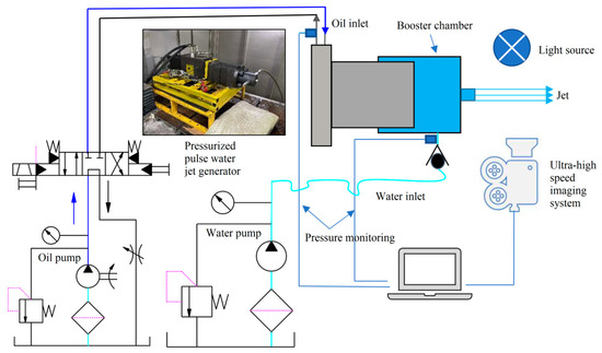
Figure 2.
Schematic diagram of pressurized pulsed water jet flow field capture system.
The ultra-high-speed imaging system uses LED light sources for illumination, and uses a uniform plate to ensure the stability and uniformity of the light source. We start the water pump and adjust it to the initial pressure pi of the booster chamber as shown in Table 1. We start the oil pump, and the booster pulse water jet generating device starts working. The nozzle sprays the booster pulse water jet, and we adjust the driving pressure pd to the specified pressure. After the pressure stabilizes, we use the ultra-high-speed imaging system to collect jet flow field information, with a sampling time of 2.34 s. Then, we trigger the method to save the collected image and turn off the oil pump and water pump. We repeat the above process to complete the experiment shown in Table 1, totaling 64 groups. Considering the pressure supply capacity and safety reliability of the engineering practice site, the inlet pressure is set below 15 MPa. At the same time, considering the integration of driving pressure and initial pressure energy supply, the initial pressure is also set below 15 MPa. We select a nozzle diameter smaller than 0.3 mm of the critical nozzle diameter.

Table 1.
Experimental Parameters.
When the water pump is turned off and the initial pump pressure of the pipeline is utilized, the initial pressure of the booster chamber is 0.2 MPa. Therefore, the initial pressure of the booster chamber without pressure is defined as 0.2 MPa.
After collecting images, the initial pulse tip velocity and penetration distance are quantitatively calculated as shown in Figure 3. Calculate the jet penetration distance using the movement distance of the pulse tip in the front and back images, and calculate the pulse tip velocity using the ratio of the jet penetration distance to the corresponding time difference.
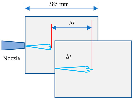
Figure 3.
Calculation method of pulse tip velocity.
3. Results
3.1. The Effect of Initial Pressure in the Booster Chamber on the Characteristics of Multiple Pulses
3.1.1. Flow Field and Multi-Pulse Characteristics without Initial Pressure
The results of ultra-high-speed imaging without initial pressure are shown in Figure 4. At this time, the flow field of the pressurized pulsed water jet exhibits discontinuous characteristics. The jet in Figure 4a maintains intact continuity, while the jet in Figure 4b exhibits discontinuity. This is caused by the motion mechanism of the pressurized pulse water jet generator. After the generator is started, the impact plunger is always in the process of impact return impact, and the process inside the booster chamber is synchronously in the process of compression water replenishment compression, as shown in Figure 5. When the device is in an impact attitude, the plunger compresses the fluid in the front-end booster chamber, and the pressure increases and continuously sprays a high-speed jet through the nozzle, as shown in Figure 4a. When the device is in a return attitude, the booster chamber supplements the fluid state. At this time, due to the lack of initial pressure in the booster chamber, the fluid without initial pressure cannot form a relatively continuous high-speed jet through the nozzle, which is manifested as a discontinuous state, as shown in Figure 4b. That is, when there is no initial pressure, the jet flow field intersects continuously and intermittently. Figure 5 clarifies the corresponding relationship between the pressure characteristics in the booster chamber and the characteristics of the jet flow field when there is no initial pressure.
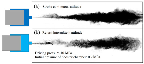
Figure 4.
Change process of jet flow field without initial pressure.
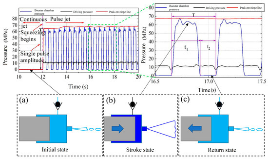
Figure 5.
Variation law of jet flow field without initial pressure.
As shown in Figure 5a, before squeezing, the fluid in the pressurized chamber is in a low-pressure state, and the jet is intermittently ejected. As shown in Figure 5b, in the squeezing posture, the fluid in the pressurized chamber is in a high-pressure state, and the jet is continuously ejected. As shown in Figure 5c, in the retreating posture, the fluid in the pressurized chamber is in a low-pressure state, and the jet is intermittently ejected.
As shown in Figure 6, when the jet is in a discontinuous state, the water pump replenishes water to the booster chamber. At this time, the flow field is in a discrete droplet state. As the impact plunger impacts the fluid in the booster chamber again, the fluid pressure in the chamber increases sharply, resulting in a multi-level pulse characteristic. The first pulse is generated in the nozzle, as shown in Figure 6a. The second pulse appears later than the first pulse and competes with the first pulse to become a tip pulse, as shown in Figure 6b.
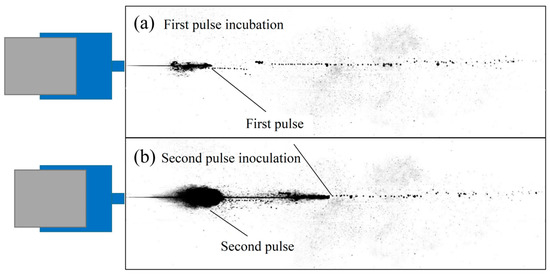
Figure 6.
Multi-pulse characteristics of jet without initial pressure.
3.1.2. Flow Field and Multi-Pulse Characteristics with Initial Pressure
As the initial pressure of the booster chamber increases, the discontinuous characteristics of the pressurized pulsed water jet flow field disappear and remain continuous. Figure 7a shows the jet structure during the impact attitude, and Figure 7b shows the jet structure during the return attitude. The diffusion degree and angle of the jet in Figure 7a are significantly greater than those in Figure 7b. This is because the pressurized pulse water jet generator compresses the fluid during the stroke, achieving a pressurized injection of the fluid. The outlet velocity of the jet during the stroke is higher than that during the return stroke, so the diffusion angle of the jet during the stroke is greater than that of the jet during the return stroke. In addition, due to the fact that during the return journey, the pressurized chamber replenishes a certain pressure of fluid through a water pump. On the basis of filling the pressurized chamber, the fluid overflows through a nozzle, forming a continuous water jet, as shown in Figure 8. At this point, as the fluid in the booster chamber is given initial pressure, the pulse water jet in the booster chamber always maintains continuity. As the stroke return cycle alternates, the jet speed fluctuates between high and low speeds.
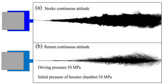
Figure 7.
Variation process of jet flow field with initial pressure.
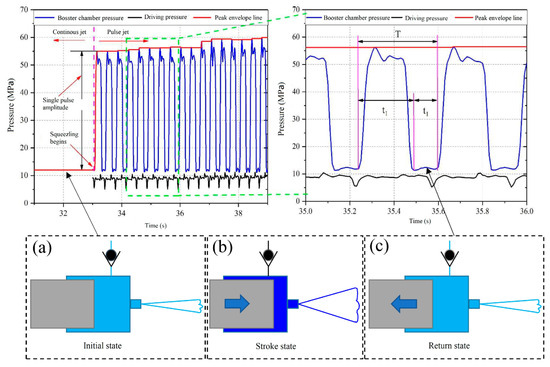
Figure 8.
Variation law of jet flow field with initial pressure.
Figure 8 clarifies the corresponding relationship between the pressure characteristics in the booster chamber and the characteristics of the jet flow field when there is initial pressure.
As shown in Figure 8a, when the fluid in the pressurized chamber is at the initial pressure, the jet forms a continuous attitude. As shown in Figure 8b, when the fluid in the pressurized chamber is in an impact attitude, the jet forms a continuous attitude. As shown in Figure 8c, when the fluid in the pressurized chamber is in a return attitude, the jet forms a continuous attitude.
As shown in Figure 9, as the initial pressure of the booster chamber increases, the jet transitions from a discontinuous state to a continuous state. As shown in Figure 9a, when the initial pressure is 0.2 MPa, the jet is in a discontinuous state. As shown in Figure 9b–f, when the initial pressure is 3–15 MPa, the jet is in a continuous state. And as the pressure of the booster chamber further increases, the diffusion angle of the jet continues to increase.
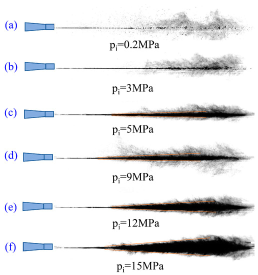
Figure 9.
Characteristics of jet return flow field at different initial pressures.
As shown in Figure 10, when the jet contains initial pressure, it still generates multi-stage pulses during the stroke process. At this time, the jet is in a continuous state, and the multi-stage pulses are difficult to observe significantly and cannot form initial pulses. Compared to when there is no initial pressure, the multi-pulse characteristics of the jet are more significant, showing a dominant multi-pulse. At this time, the multi-pulse characteristics of the jet are not significant enough, showing an implicit multi-pulse. As shown in Figure 10a, the first pulse was incubated near the nozzle position at 2.1 ms. As shown in Figure 10b, the second pulse was incubated near the nozzle position at 5.8 ms. As shown in Figure 10c. At 6.3 ms, a third pulse was incubated near the nozzle position. The prominent features of the three pulses are the sudden appearance of a thickened jet and its rapid disappearance.
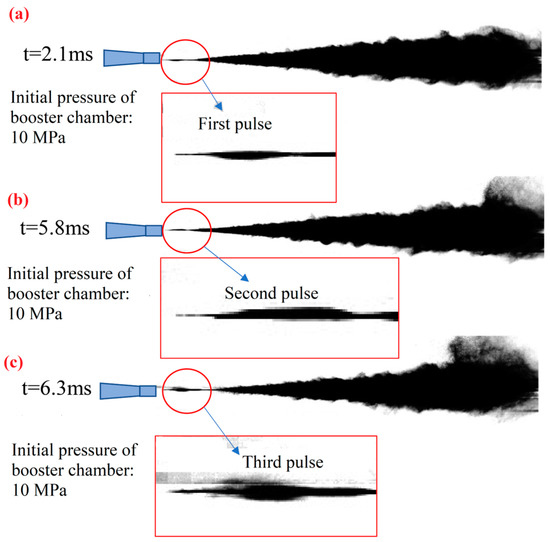
Figure 10.
Multi-pulse characteristics of jet with initial pressure.
3.2. Impact of Driving Pressure on Multi-Pulse Characteristics
When the initial pressure is not included, the jet exhibits dominant multi-pulse. In order to facilitate the accuracy of subsequent multi-pulse calibration and quantitative calculation, the multi-pulse characteristics of the jet under different gradient driving pressure conditions without initial pressure were further obtained, as shown in Figure 11.
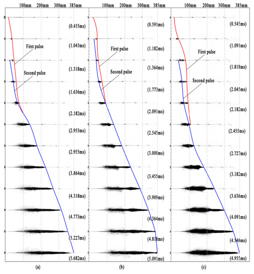
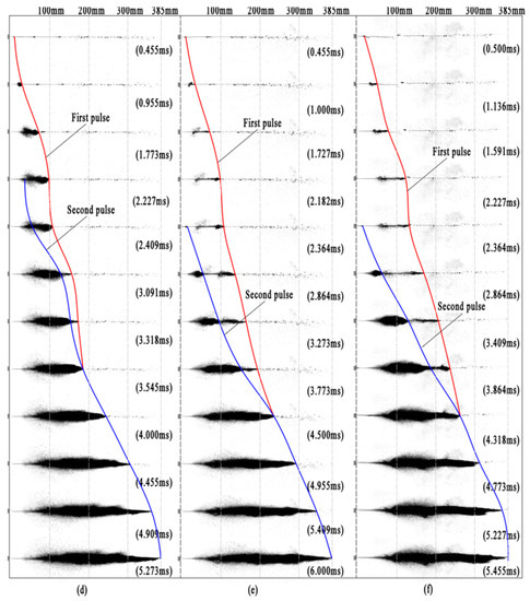
Figure 11.
Multi-pulse change rule under different driving pressure conditions (a) driving pressure 5.2 MPa; (b) drive pressure 6.9 MPa; (c) drive pressure 8.6 MPa; (d) drive pressure 10.3 MPa; (e) drive pressure 12.1 MPa; (f) drive pressure 13.8 MPa.
Extracting the tip velocity and penetration distance of the jet in different pressure gradient flow fields in Figure 10 can obtain Figure 12, Figure 13 and Figure 14.
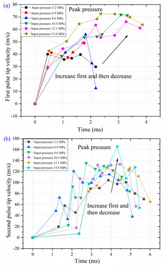
Figure 12.
(a) The change trend of the instantaneous velocity of the first pulse tip with time; (b) the change trend of instantaneous velocity at the second pulse tip with time.
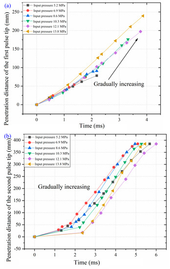
Figure 13.
(a) The change trend of the penetration distance of the first pulse tip with time; (b) the change trend of the penetration distance of the second pulse tip with time.
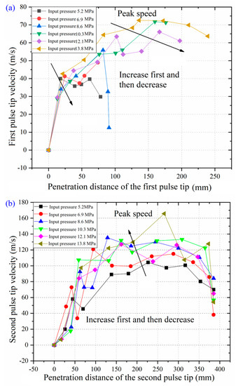
Figure 14.
(a) The instantaneous velocity of the first pulse tip changes with the penetration distance; (b) the change trend of the instantaneous velocity of the second pulse tip with the penetration distance.
From Figure 12, Figure 13 and Figure 14, it can be seen that as time increases, the instantaneous velocities of the first and second tips of the pulse jet first increase and then decrease. And at driving pressures of 5.2 MPa, 6.9 MPa, and 8.6 MPa, the instantaneous velocity decrease rate at the tip of the first pulse is higher than that at higher driving pressures, and the maintenance time of the first pulse is shorter. As the pulse jet propagates in the air, the penetration distance of the first pulse of the pulse jet increases with the increase in driving pressure, and the penetration distance of the second pulse of the pulse jet also shows an increasing trend with the increase in driving pressure. Within the same time, the penetration distance of the tip of the second pulse with high driving pressure is greater than that of low driving pressure, and the high driving pressure reaches the endpoint of the captured image in a shorter time. In addition, as the penetration distance of the pulse jet increases, the velocities of the first and second pulse tips first increase and then decrease. For the first pulse, the velocity change curve of the jet shows a “semi saddle shaped” formation, while for the second pulse, the velocity change of the jet shows a “saddle shaped” formation. This is because the first pulse jet tip only completes the acceleration process. When the jet tip begins to enter the process of velocity attenuation, it is covered by the second pulse, and the velocity attenuation process of the first pulse tip ends. Therefore, the curve shows a “semi saddle shaped” formation. For the second pulse, within the window range where the ultra-high-speed camera is located, the jet completes a relatively complete process of velocity climb and velocity decay, so the velocity curve at the tip of the second pulse shows a “saddle shaped” formation.
Meanwhile, as the driving pressure increases, the peak velocity of the first pulse tip and the peak velocity of the second pulse tip show an overall upward trend, as shown in Figure 15. As the driving pressure increases, the peak velocities of the first and second pulse tips continue to increase.
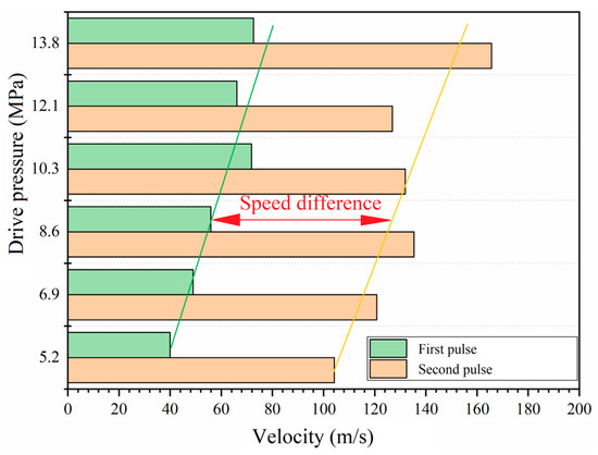
Figure 15.
Variation trend of peak velocity at the tip of pulsed water jet under different gradient driving pressure.
In addition, as shown in Figure 16, as the driving pressure increases, the distance between the initiation positions of the first pulse and the second pulse gradually increases. By fitting the experimental results, it was found that there is a linear distribution between the driving pressure and the initial distance, and the judgment coefficient R2 = 0.91, indicating that the fitting results are very close, and the duration and penetration distance of the first pulse tip also increase synchronously, as shown in Figure 17. These two fully demonstrate that as the driving pressure increases, the instantaneous velocity of the first pulse increases synchronously, and the position and time of the second pulse initiation do not show significant changes. By fitting the experimental results, it was found that the driving pressure is linearly distributed with the duration of the first pulse and the injection distance, and the determination coefficients R2 are 0.79 and 0.89, respectively, indicating a good fitting effect.
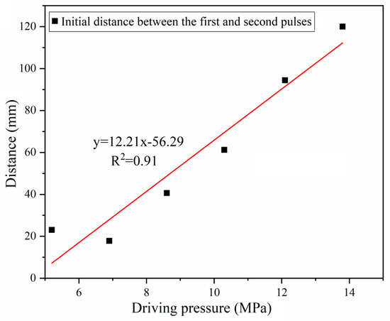
Figure 16.
Initial distance variation of the first pulse and the second pulse under different gradient driving pressure.
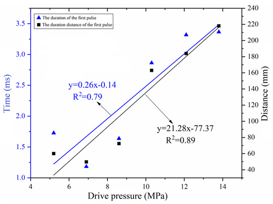
Figure 17.
Duration and penetration distance of the first pulse tip under different driving pressures.
As shown in Figure 18, as the driving pressure increases, the peak velocity of the initial pulse further increases, and all the peak velocities of the initial pulse are generated at the second pulse. Meanwhile, as the driving pressure increases, the position where the initial pulse peak velocity occurs shifts away from the nozzle, indicating that the optimal target distance position increases with the increase in driving pressure. This is because as the driving pressure increases, the second pulse obtains greater pressure energy per unit time, and the core section of the jet maintains a longer attenuation distance, further increasing the peak velocity of the initial pulse while shifting the position of the initial pulse to a further distance. By fitting the experimental results, it was found that there is a linear relationship between the driving pressure and the location of the initial pulse, with a judgment coefficient of R2 = 0.65, indicating that the fitting results are relatively close.
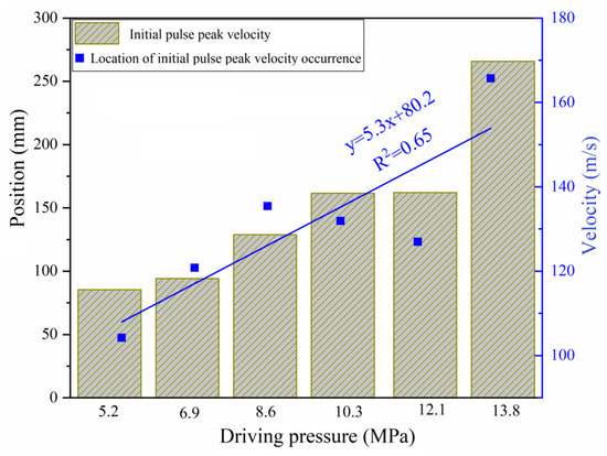
Figure 18.
Peak velocity and occurrence distance of initial pulse under different driving pressures.
3.3. Subsection
Further analysis of the relationship between the initial pulse velocity and the theoretical velocity shows that, with the removal of two singular points, the experimental results are compared with the theoretical results. Under different driving conditions, the initial pulse peak velocity maintains relative consistency with the theoretical velocity of the continuous jet outlet under corresponding pressure conditions. From Figure 5 and Figure 12, it can be seen that the initial pulse peak velocity occurs at a time when the pressure in the booster chamber is still climbing, meaning that the initial pulse peak velocity is not equal to the jet peak velocity at this time. However, the peak velocity of the initial pulse can be estimated using the approximate relationship shown in Figure 19. The research results provide reference and validation for the subsequent evaluation of the velocity distribution characteristics of jets under different driving conditions, and provide a basis for further utilizing water hammer for rock fragmentation.
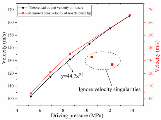
Figure 19.
Initial pulse peak velocity and theoretical velocity under different driving pressures.
4. Conclusions
A pressurized pulsed water jet flow field acquisition system was constructed, and the effects of two key control parameters, initial pressure and driving pressure, on the characteristics of multiple pulses were experimentally obtained. The competition relationship between different pulses and initial pulses during the multi-pulse process was analyzed. The main research conclusions are as follows:
- (1)
- As the initial pressure of the pressurized chamber increases from “no pressure” to “with pressure”, the flow field of the pressurized pulsed water jet changes from a discontinuous state to a continuous state. At the same time, the multi-pulse feature during the stroke stage changes from dominant multi-pulse to implicit multi-pulse. This provides a theoretical reference for the switching between discontinuous and continuous states of the jet during the application process;
- (2)
- As the driving pressure increases, the instantaneous velocity and penetration distance of the first and second pulse tips increase, and the difference in the initial positions of the first and second pulses further intensifies. At the same time, the duration and penetration distance of the first pulse tip increase with the increase in driving pressure, the peak velocity of the initial pulse increases with the increase in driving pressure, and the location of the initial pulse shifts away from the nozzle with the increase in driving pressure. This indicates the regulatory effect of driving pressure on the initial pulse, providing a theoretical reference for the subsequent modulation of jets at different initial pulse positions;
- (3)
- When there is no initial pressure in the booster chamber, the initial pulse peak velocity remains consistent with the theoretical outlet velocity of the continuous jet under different driving pressure conditions. This indicates that the driving pressure is decisive for the initial pulse peak velocity, providing a theoretical reference for the demand for peak velocity in practice.
Author Contributions
Conceptualization, Y.Z. and Q.L.; methodology, Y.Z. and Q.L.; validation, Y.Z. and Q.L.; formal analysis, Y.Z.; investigation, Y.Z. and Q.L.; resources, Q.L. and Y.Z.; data curation, Y.Z.; writing—original draft preparation, Y.Z.; writing—review and editing, Y.Z. and Q.L.; visualization, Y.Z.; supervision, Y.Z.; project administration, Y.Z.; funding acquisition, Q.L. All authors have read and agreed to the published version of the manuscript.
Funding
This research was funded by the National Natural Science Foundation Outstanding Youth Fund Project (grant no. 51625401) and the Program for Changjiang Scholars and Innovative Research Team in Chongqing University (grant no. IRT17R112).
Data Availability Statement
Data presented in this study are available in the article.
Acknowledgments
We are very grateful to Yuanfei Ling of the Chongqing University for his experiment.
Conflicts of Interest
The authors declare no conflict of interest.
References
- Li, G.; Shen, Z. Advances in researches and applications of water jet theory in petroleum engineering. Pet. Explor. Dev. 2005, 1, 96–99. [Google Scholar]
- Shen, Z.; Li, G.; Wang, R. Application and prospects of water jet technology in petroleum engineering. Eng. Sci. 2002, 12, 60–65. [Google Scholar]
- Lu, Y.Y.; Ge, Z.L.; Li, X.H.; Chen, J.F.; Liu, Y. Investigation of a self-excited pulsed water jet for rock cross-cutting to uncover coal. J. China Univ. Min. Technol. 2010, 39, 55–58+69. [Google Scholar]
- Liu, Y.; Lu, Y.; Li, X.; Xia, B. Application of drilling in roof or floor with high pulse pressure water jet to improve gas drainage. J. China Coal Soc. 2010, 35, 1115–1119. [Google Scholar]
- Han, W. Experimental study on rock breaking of TBM disc cutter assisted by the forward high pressure water jet precutting. Railway Standard Des. 2022, 67, 130–135. [Google Scholar]
- Huang, Z.; Cai, C.; Li, G.; Tian, S. Flow behavior and particle acceleration effect of abrasive liquid nitrogen jet. J. China Univ. Pet. (Ed. Nat. Sci.) 2016, 40, 80–86. [Google Scholar]
- Lu, Y.; Zhang, S.; Liu, Y.; Lu, Z.; Jiang, L. Analysis on stresses wave effect during the process of rock breaking by pulsed jet. J. Chongqing Univ. 2012, 35, 117–124. [Google Scholar]
- Hsu, C.Y.; Liang, C.C.; Teng, T.L.; Nguyen, A.T. A numerical study on high-speed water jet impact. Ocean Eng. 2013, 72, 98–106. [Google Scholar] [CrossRef]
- Tripathi, R.; Hloch, S.; Chattopadhyaya, S.; Klichová, D.; Ščučka, J.; Das, A.K. Application of the pulsating and continous water jet for granite erosion. Int. J. Rock Mech. Min. 2020, 126, 104209. [Google Scholar] [CrossRef]
- Nag, A.; Hvizdos, P.; Dixit, A.R.; Petrů, J.; Hloch, S. Influence of the frequency and flow rate of a pulsating water jet on the wear damage of tantalum. Wear 2021, 477, 203893. [Google Scholar] [CrossRef]
- Marzouk, S.; Aissia, H.B.; Palec, G.L. Numerical study of amplitude and frequency effects upon a pulsating jet. Comput. Fluids 2015, 123, 99–111. [Google Scholar] [CrossRef]
- Lu, Z.; Lu, Y.; Hood, M.; Pan, L.; He, P. Numerical simulation and analysis on the flow field structure and hard rock erosion potential of a disc-slotted pulse water jet. J. Vib. Shock 2017, 36, 180–185. [Google Scholar]
- Pan, Y.; Yang, F.; Zhang, Z.; Ma, H. Numerical simulation of coal rock fragmentation characteristics under interrupted pulse water jet. J. Vib. Shock 2021, 40, 283–288. [Google Scholar]
- Zhang, Y.; Lu, Y.; Tang, J.; Ling, Y.; Wang, L.; Yao, Q.; Zhu, Z. Development and application of rock breaking platform with variable cross section extrusion pulsed water jet. J. Mech. Sci. Technol. 2022, 36, 2837–2848. [Google Scholar] [CrossRef]
- Ling, Y.; Ge, Z.; Tang, J.; Lu, Y.; Zhang, Y.; Wang, L. Development of a hydraulically controlled piston-pressurized pulsed water jet device and its application potential for hard rock breaking. Rev. Sci. Instrum. 2021, 92, 085101. [Google Scholar] [CrossRef] [PubMed]
- Tang, J.; Wang, L.; Lu, Y.; Ling, Y.; Zhang, Y. An experimental study on visualization of pulsation characteristics of supercharged pulsed water jet. J. Vib. Shock 2021, 40, 1–8. [Google Scholar]
- Ding, T.; Zhang, R.; Ying, C.; Song, Q. Development and application of the pollutant diffusion testing apparatus based on the image analysis. J. Saf. Environ. 2016, 16, 247–251. [Google Scholar]
- Li, B.; Wang, H.; Yuan, B. Study on the attenuation effect of water protection layer on the velocity of jet tip. Chin. J. High Press. Phys. 2018, 32, 104–108. [Google Scholar]
- Ye, Y.; Wang, W.; Li, Z.; Li, J.; Liu, Z.; Zhong, J.; Li, J.; Shang, C.; Luo, Z.; Li, X.; et al. High-speed photography and pulsed in-line holography diagnostics of microjet. Chin. J. High Press. Phys. 2009, 23, 471–475. [Google Scholar]
- Liu, W.; Lu, Y.; Kang, Y.; Yan, J.; Lee, C.F. Macroscopic characteristics of flash-boiling spray focused on plume interaction. Int. J. Heat Mass Transf. 2021, 170, 120999. [Google Scholar] [CrossRef]
- Lu, Z.; Qin, Z.; Hood, M.; Lu, Y.; Tadic, D. Numerical modelling of percussion water jets driven by multiple collisions. Proc. Inst. Mech. Eng. Part C J. Mech. Eng. Sci. 2014, 229, 976–984. [Google Scholar] [CrossRef]
- Matthujak, A.; Kasamnimitporn, C.; Sriveerakul, T. Comparative visualized investigation of impact-driven high-speed liquid jets injected in submerged water and in ambient air. J. Vis. 2020, 23, 395–408. [Google Scholar] [CrossRef]
- Říha, Z.; Zeleňák, M.; Kruml, T.; Poloprudský, J. Comparison of the disintegration abilities of modulated and continuous water jets. Wear 2021, 478–479, 203891. [Google Scholar] [CrossRef]
- Zeleňák, M.; Říha, Z.; Jandačka, P. Visualization and velocity analysis of a high-speed modulated water jet generated by a hydrodynamic nozzle. Measurement 2020, 159, 107753. [Google Scholar] [CrossRef]
- Matthujak, A.; Kasamnimitporn, C.; Sittiwong, W.; Pianthong, K.; Takayama, K.; Milton, B.E. Characteristics of impact-driven high-speed liquid jets in water. Shock Waves 2013, 23, 105–114. [Google Scholar] [CrossRef]
- Zelenak, M.; Foldyna, J.; Scucka, J.; Hloch, S.; Riha, Z. Visualisation and measurement of high-speed pulsating and continuous water jets. Measurement 2015, 72, 1–8. [Google Scholar] [CrossRef]
- Pianthong, K.; Matthujak, A.; Takayama, K.; Milton, B.E.; Behnia, M. Dynamic characteristics of pulsed supersonic fuel sprays. Shock Waves 2008, 18, 1–10. [Google Scholar] [CrossRef]
- Milton, B.E.; Pianthong, K. Pulsed, supersonic fuel jets—A review of their characteristics and potential for fuel injection. Int. J. Heat Fluid Flow 2005, 26, 656–671. [Google Scholar] [CrossRef]
- Lu, Y.; Zhang, Y.; Tang, J.; Yao, Q. Switching mechanism and optimisation research on a pressure-attitude adaptive adjusting coal seam water jet slotter. Int. J. Min. Sci. Technol. 2022, 32, 1167–1179. [Google Scholar] [CrossRef]
Disclaimer/Publisher’s Note: The statements, opinions and data contained in all publications are solely those of the individual author(s) and contributor(s) and not of MDPI and/or the editor(s). MDPI and/or the editor(s) disclaim responsibility for any injury to people or property resulting from any ideas, methods, instructions or products referred to in the content. |
© 2023 by the authors. Licensee MDPI, Basel, Switzerland. This article is an open access article distributed under the terms and conditions of the Creative Commons Attribution (CC BY) license (https://creativecommons.org/licenses/by/4.0/).