Article

Design Optimization of Electrical Structure Parameters of Induction Asynchronous Mechanical–Electric–Hydraulic Power Coupler

College of Mechanical and Electrical Engineering, Qingdao University, Qingdao 266071, China
*
Author to whom correspondence should be addressed.
Processes 2023, 11(7), 2217; https://doi.org/10.3390/pr11072217
Submission received: 30 June 2023 / Revised: 20 July 2023 / Accepted: 21 July 2023 / Published: 24 July 2023

Abstract

:
In response to the problems of considerable size, loose structure, and low energy conversion efficiency of multi-energy power coupling devices, this paper makes improvements based on the mechanical–electric–hydraulic power coupler proposed by our research group. We propose a new asynchronous mechanical–electric–hydraulic power coupler (IA-MEHPC). This mechanism integrates a traditional three-phase asynchronous motor with a swashplate axial piston pump/motor to realize the mutual conversion of electrical, mechanical, and hydraulic energy. Compactness, efficiency, and adaptability are the distinguishing features of the complex. This paper builds a three-dimensional model of the IA-MEHPC and a two-dimensional theoretical model of the electrical structure (motor part). Moreover, the electrical structure parameters of the IA-MEHPC are optimized using an approximate response surface-based optimization method. The maximum motor peak torque and minimum torque fluctuation are identified as optimization objectives, and we obtain the optimal combination of parameters. The simulation results show that, compared to the pre-optimized structure, the peak motor torque of the optimized IA-MEHPC is increased by 5.78%, and the torque pulsation coefficient is reduced by 15.83%, in line with engineering practice expectations. This paper innovatively proposes and optimizes IA-MEHPC, which is significant for developing hybrid mechanical devices and subsequent research.

1. Introduction

1.1. Research Motivation

With the introduction of national carbon peak and carbon neutrality targets, the research and application of new energy vehicles are becoming increasingly common, where pure electric vehicles (EVs) dominate the new energy market. However, owing to the limitations of battery defects in EVs [1], frequent start-stop can generate peak torque [2]. Significantly reduced battery life and range, and there are obvious disadvantages, such as high battery cost and long charging time. Hybrid vehicles (HVs) have also gained some degree of popularity in recent years, and vehicle hybrid systems are considered an essential step in controlling global warming and related vehicle emissions [3]. With the growing sophistication of hybrid electric vehicles (HEVs) and the development of electro–hydraulic hybrid technology, the researchers found that hydraulic and electric systems can significantly optimize mechanical energy output. However, few technologies combine mechanical, hydraulic, and electrical energy, not to mention the lack of research on coupling devices for the three types of energy. The group then proposed a mechanical–electric–hydraulic power coupler (MEHPC), which uses a conventional motor to integrate with a hydraulic pump/motor [4]. The new hybrid vehicle MEHPCV equipped with MEHPC enables the interconversion of electrical, mechanical, and hydraulic energy [5]. The MEHPC uses a permanent magnet synchronous motor and a swashplate DC piston pump. However, the presence of permanent magnets makes assembly difficult, so achieving assembly and improved performance of the MEHPC will be of great significance for future research on the MEHPC and innovation in multi-source power coupling devices. The optimization of peak torque and torque fluctuation, as important parameters of motor performance, is of great significance for the performance improvement of the motor. However, there are few optimization methods in the literature with a targeted approach, so it is necessary to adopt a suitable optimization method for the motor parameters. The IA-MEHPC proposed in this paper implements an improvement of MEHPC. The parameters of the IA-MEHPC electrodynamic structure are optimized using an innovative response surface optimization algorithm.

1.2. Literature Review

As the main force behind hybrids, the electrification of transport is likely to be the solution for the next generation of transport [6]. HEVs are vehicles with a mixture of both internal combustion engines and electric motors. The power coupling effect of a multi-source power coupling system realizes this mixing, and research into this electromechanical coupling system is essential in developing HEVs. Li proposed an integrated model of an electric vehicle with an in-wheel motor [7]. The IWM-EV consists of an electric wheel with a drive motor and vehicle powertrain components, which are electromechanically coupled as critical components. Hu designed an integrated electric drive system (IEDS) consisting of a permanent magnet synchronous motor and a helical gear reducer [8], and a model was designed to reduce torsional vibrations in the driveline during rapid acceleration. Electromechanical coupled systems are also used in braking systems, and electromechanical brakes have the potential to replace hydraulic brakes [9]. However, electromechanically coupled systems still have apparent disadvantages, such as electromechanical coupling effects, and attenuating the negative aspects of electromechanical coupling in HEVs is currently the focus of research and development for this system [10]. At the same time, the lower power density allows only a small amount of braking energy to be recovered from hybrid electric vehicles [11]. Electro–hydraulic hybrid technology, as a new configuration, has become one of the most critical and advanced branches in the field of new energy and construction machinery [12]. As a typical energy storage device in a hydraulic system, the hydraulic accumulator has the advantage of higher power density and lower energy density [13]. Adding a high power density hydraulic system can reduce the power consumption and battery discharge pressure of the electric power system. One can extend the vehicle’s driving range and improve the life of the battery pack. A hydraulic hybrid vehicle (HHV) has an engine as the primary power source and hydraulic energy as the auxiliary power source, which supplies both hydraulic and mechanical energy in the specific operating conditions of the vehicle [14]. Hydraulic systems offer unique advantages in terms of efficient energy recovery and utilization [1], and a hydraulic hybrid vehicle with an adaptive system was proposed in [15], which offers higher reliability and lower costs for adaptive vehicle mode switching. The efficiency of hydraulic regenerative braking has also been improved. The group proposed a new parallel electro–hydraulic hybrid electric vehicle (PEHHEV), which features multiple operating modes and power sources [16]. From the former study, energy storage is one of the critical factors limiting the development of hybrid drive technology [17]; the advantages and disadvantages of each of the hydraulic and electrodynamic systems are apparent, and the electro–mechanical–hydraulic coupling system takes advantage of the strengths and weaknesses of the MEHPC, which is groundbreaking and necessary.
Motors play an important role in HV, with induction asynchronous motors considered one of the most popular motors in the industry [18], and the performance of the motor directly determines the performance of the HV. High-performance motor drive applications require smooth operation and minimal torque fluctuations [19]. The ability to output high peak torque at regular intervals is a fundamental requirement for motor design. Scholars have conducted much research on how to control motor torque fluctuations and increase peak motor torque. A simple and effective method for reducing torque pulsation in direct torque control (DTC) of induction motors is presented in [20], and simulation and experimental results verify the effectiveness of the method. Another improved control method for SWBSRMs is based on DTC and DFC; this method can obtain both a high torque-to-ampere ratio and low torque pulsation [21]. Unreasonable motor structure parameters can also lead to inefficient motors [22], and reasonable optimization of motor structure dimensions is necessary. Torque pulsations caused by structural dimensions such as air gaps limit the steady-state performance of the servo system [23]. A robustness-oriented approach for the optimal design of permanent magnet motors was presented in [24]. The method takes the effect of parameter fluctuations on motor performance as a design objective and obtains deterministic motor structures. H.B. Eratan proposed a method for calculating single-phase permanent magnet (SPPM) motor parameters, including motor dimensions and material properties, which was studied with the aim of developing a method for calculating SPPM performance [25]. A Pigeon-inspired optimization (PIO) population intelligence optimization algorithm was proposed in [26], which was used to solve the multi-objective optimization problem in the parametric design of brushless DC motors.
Parameter optimization cannot be separated from optimization algorithms, and the response surface algorithm, as a highly accurate parameter optimization algorithm, is widely used in various fields. Kucukkoc proposed response surface-related parameter optimization to determine the optimal parameters of a genetic algorithm (GA) [27]. Bakhtiari applied the response surface algorithm to the optimization of a torsional extrusion process [28]. A new design of experiments approach was used in [29] to obtain response surfaces for flexural loading of laminated composites. However, few studies have applied the response surface optimization algorithm to the optimization of motor parameters, which after response surface optimization, would result in more accurate and tailored structural parameters of the motor to the expectations of engineering practice.
The IA-MEHPC system proposed in this paper is a pioneer in the interconversion of electrical, mechanical, and hydraulic energy. This device can give good play to the advantages of hydraulic systems and electric power systems, and its coupling method for multi-source power coupling devices provides an important reference; this paper applies the response surface optimization algorithm to the optimization of motor parameters to achieve the purpose of optimizing the performance of IA-MEHPC motor and provides a reasonable optimization method for optimizing motor parameters.

1.3. Contribution of This Paper

  • A new multi-source power coupling device, IA-MEHPC, is proposed and modeled in three dimensions in this paper;
  • IA-MEHPC electrodynamic torque optimization response surface model was established by co-simulation with Maxwell and Workbench (the co-simulation environment proposed by ANSYS);
  • The IA-MEHPC electrical structure parameters are optimized to enable its motor performance to be improved.

1.4. Article Structure

Section 2 is the working principle of IA-MEHPC, which introduces in detail the composition and working principle of IA-MEHPC and its application on the whole vehicle. Section 3 is the design of the IA-MEHPC electrodynamic structure optimization model, which establishes the torque optimization response surface model in Workbench and introduces the optimization process in detail. Section 4 is the analysis of optimization results, which compares the initial structure parameters, and the optimized Section 4 presents the analysis of the optimization results, comparing the effect of the initial structure parameters and the optimized parameters on the motor performance. The Section 5 is the conclusion, including a summary and prospect.

2. IA-MEHPC Working Principle and Application

2.1. Structure and Working Principle of IA-MEHPC

Figure 1 shows the overall structure and working principle of IA-MEHPC. Figure 1a shows the overall structural composition of the IA-MEHPC: mechanical assembly, swashplate hydraulic assembly, motor assembly, and variable mechanism coupled with the motor. The main drive shaft in the structure transmits mechanical energy to the other components; the swashplate plunger pump of the swashplate hydraulic assembly is the main element; the cooperation of multiple motion subsets can achieve mutual energy transformation; and the induction asynchronous motor of the motor assembly is the main element, as shown in Figure 1b. The induction motor rotor has a plug hole, and the structure of the integrated design realizes the mutual transformation of electrical energy with mechanical and hydraulic energy. The variable mechanism of the coupler is mainly a worm gear element, which is hinged to the swashplate of the swashplate piston pump, and the variable control of the coupler is achieved by changing the inclination of the swashplate.
The IA-MEHPC structure design combines the swash plate piston pump and induction asynchronous motor and couples them with the motor to ensure that the motor works while the motor and piston pump functions can be realized. The MEHPC is designed to convert mechanical, electrical, and hydraulic energies to each other at will. The highly integrated and compact structure of IA-MEHPC can be seen in Figure 1, featuring high adaptability and easy installation. IA-MEHPC has greatly improved power and enhanced energy recovery capability by coupling multiple power units.
IA-MEHPC energy conversion process is as follows:
(1) Mechanical energy into hydraulic energy: mechanical energy acts on the drive shaft to drive the cylinder for rotational movement, the plunger also follows the cylinder for rotational movement, and the plunger performs reciprocating linear movement under cooperation with the slide track, swash plate, and other components.
(2) Hydraulic energy is converted into mechanical energy: the high-pressure oil enters the plunger chamber from the inlet chamber, the plunger moves out of the chamber and drives the cylinder body to rotate with the cooperation of the swashplate, which in turn drives the drive shaft to rotate, outputting mechanical energy to the outside.
(3) Mechanical energy into electrical energy: mechanical energy is produced through the drive shaft drive induction asynchronous motor rotor rotation, the rotor in the stator’s magnetic field for rotation, and the rotor (that is, closed circuit) by the role of the stator’s magnetic field, thus generating current through the wire outward output.
(4) Conversion of electrical energy into mechanical energy: the introduction of a three-phase symmetrical alternating current produces a rotating magnetic field that cuts the rotor winding, thus generating an induced current in the rotor winding (the rotor winding is a closed path). The current-carrying rotor conductor generates an electromagnetic force under the action of the rotating stator magnetic field, thus creating an electromagnetic torque on the motor’s rotor shaft.
In addition, when the electro–hydraulic coupling is working in single-to-multiple or multi-to-single energy conversion, the operating mode can be selected according to the actual operating environment.

2.2. Application of IA-MEHPC in HV

The IA-MEHPC’s multiple energy conversions enable it to meet the needs of a variety of vehicle operating conditions and have a broad application prospect in hybrid vehicles; the electro–mechanical–hydraulic coupler in the vehicle’s application schematic diagram is shown in Figure 2.
The system consists of the IA-MEHPC, high-pressure accumulator (HPA), low-pressure accumulator (LPA), clutch, hydraulic control unit, power converter, and power battery.
The system uses electrical power as the primary power source and hydraulic power as an auxiliary power source. When the system is in operation, the controller receives acceleration and braking signals from the pressure sensors, which are transmitted to the hydraulic control unit via the onboard controller to adjust the displacement of the hydraulic pump/motor. When the vehicle starts, there is no electric power output to reduce the impact of high current and torque on the motor. The hydraulic pump/motor acts as a motor and hydraulic oil flows from the HPA to the LPA. The motor traction system is engaged after the hydraulic power drives the vehicle to accelerate to a specific lower speed. When the pressure in the hydraulic accumulator is less than the minimum working pressure of the accumulator, the hydraulic accumulator is unable to release the hydraulic oil; at this time, the battery pack drives the hydraulic pump/motor to flush the hydraulic accumulator, and a hydraulic pump can also be a pump/motor; the oil flows from the LPA to the HPA. In the acceleration and climbing phase, the electric power intervenes and works in cooperation with the hydraulic pump/motor to carry out torque coupling, output power, and drive the vehicle to accelerate during the acceleration and climbing phases; the electric power intervenes and works in cooperate with the hydraulic pump/motor to deliver the torque coupling and drive the vehicle. During the constant speed phase, the hydraulic system does not intervene, and the vehicle is driven by electric power alone due to the stable speed and low external loads. When braking, the control unit determines the specific braking mode to be used, depending on the energy status of the battery and accumulator and the driver’s braking intentions. During braking, the hydraulic regenerative braking mode, the electric regenerative braking mode, or the mechanical braking mode can be selected. In addition, in the case of emergency braking, only mechanical braking is applied without motor regenerative braking in order to ensure safety.
The design of IA-MEHPC solves the problem of energy power under various complex working conditions. The new electric vehicle equipped with IA-MEHPC solves the problems of poor power systems, imperfect control systems, and irrational mode matching of traditional electric vehicles. It has significant advantages in energy saving and energy recovery.

3. Electrical Structure Design Optimization Model

The optimization of the electrical structure aims to achieve the highest efficiency and smoothest operation. The highest efficiency is mainly reflected in the maximum adequate torque, while the smooth operation is reflected in the torque fluctuation. The calculation of torque and ripple torque coefficient needs to be achieved by the finite unit method (a numerical solution method); the increase in calculation precision inevitably means an increase in calculation amount, and the computational cost is too high due to the continuous call of finite element analysis software in the optimization. Therefore, selecting an optimization method suitable for torque and fluctuation is very important. This paper intends to use the response surface approximation model for optimization. The finite element model of the electrodynamic structure needs to be established first. Then the response surface optimization module in Workbench software(2020 R1) is used for experimental design to obtain the response surface approximation model.

3.1. Finite Element Model

This paper uses the design parameters of the initial IA-MEHPC electrical structure, as shown in Table 1, to build a two-dimensional model of the electrical structure in the finite element simulation software Maxwell (Maxwell 16) on the basis of a three-dimensional model.
The overall model is shown in Figure 3, with the stator, stator winding, rotor, rotor winding, plunger bore, and rotor shaft, a total of six structures, set in the band region for rotational movement and in the out region for the whole model.

3.2. Selection of Optimization Parameters of IA-MEHPC

The main body of the IV-MEHPC consists of a swashplate axial piston pump and a three-phase squirrel-cage induction asynchronous motor. Since the plunger hole of the plunger pump is set in the rotor of the induction asynchronous motor, the size of the plunger hole distribution circle affects the setting of the rotor slot and directly determines the assembly of the motor and the plunger pump in the IV-MEHPC, so the selection of the plunger hole distribution circle and the axial length of the rotor slot as optimization variables is necessary.
The size of the air gap greatly influences the performance and operational reliability of the electrodynamic structure of the IA-MEHPC. The permeability of the air gap is minimal, and increasing the air gap means increasing the resistance of the entire magnetic circuit. The magnetic induction strength is inversely proportional to the magnetic resistance of the magnetic circuit, so the more significant the thickness of the air gap, the greater the loss of magnetic energy and the more significant the corresponding drop in torque value. The motor air gap cannot be too small; if it is too small, it makes the motor torque fluctuations too large, and a stator-rotor phase sassafras phenomenon may even appear, so the air gap is an optimization of the parameters.
If the stator slot size is different, it affects the size of the motor counter-electromotive force, has an impact on the motor armature voltage, and then affects the size of the motor output torque value, affecting the motor work performance. On the other hand, the stability of the motor output torque is affected if the slot size is too large or too small, which produces torque pulsation too high, and the torque output cannot be stable, affecting the motor work performance. Therefore, the stator slot width was chosen as an optimization parameter. Figure 4 shows the optimization parameters.

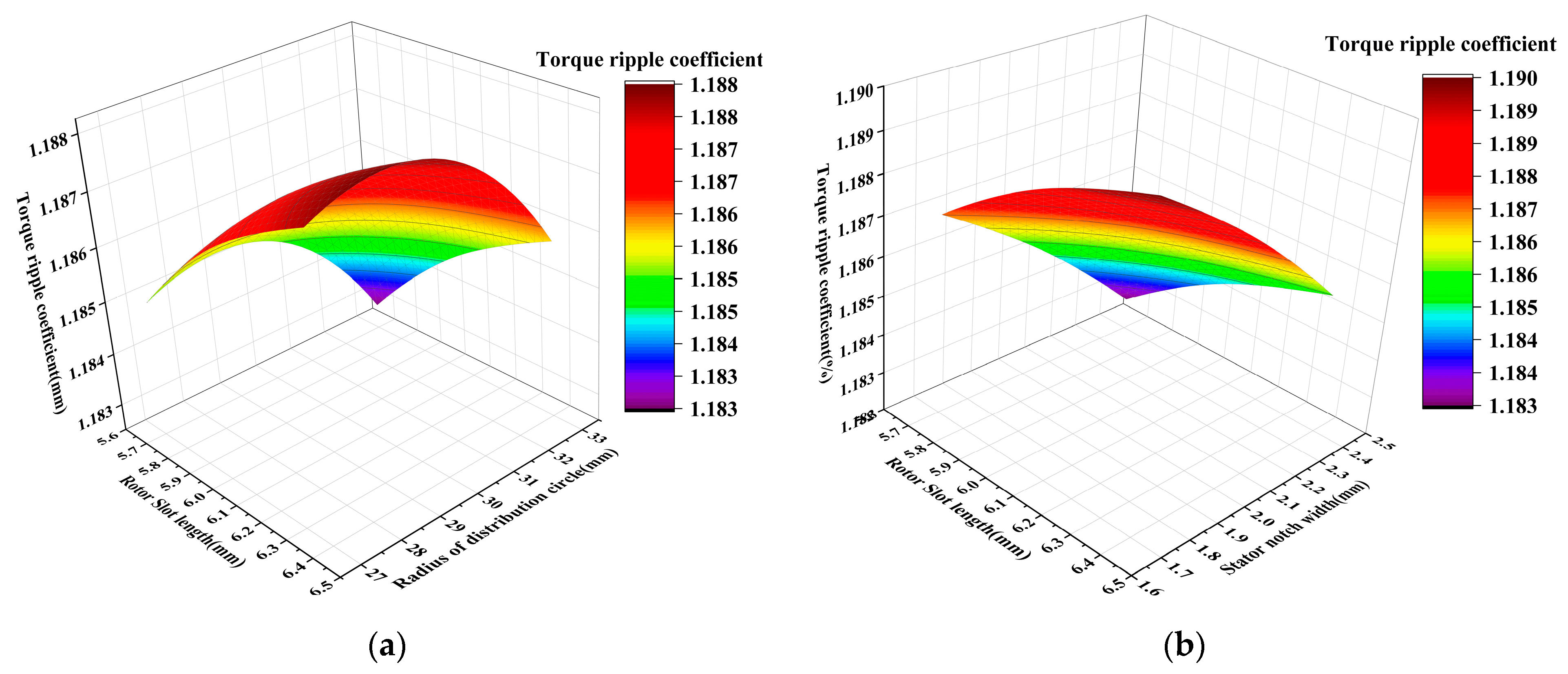
3.3. Response Surface Algorithm

The response surface algorithm is implemented as a combination of mathematical and statistical methods, composing parameters of several variables for experiments, fitting regression analysis to experimental sample data by fitting regression equations, and analyzing the results to obtain the best parameters. In the optimization of the IA-MEHPC electric structure parameters, the stator inner diameter and rotor outer diameter (air gap), stator slot width, rotor slot axial length, and plunger bore distribution circle radius was selected as optimization variables, with peak torque and torque fluctuation as optimization targets. The specific mathematical model for optimization using the response surface method is expressed as follows:
x x 1 , x 2 , x 3 , x 4 y 1 max y 2 min 0.25 x 1 1 1.53 x 2 1.87 5.2 x 3 6.6 27 x 4 33
where x is the optimization variable, y is the optimization target, x1 is the air gap length, x2 is the stator slot width, x3 is the rotor slot axial length, x4 is the plunger bore distribution circle radius, y1 is the peak torque, and y2 is the torque fluctuation.
Optimization using the response surface method will, after a number of experimental calculations, fit the relationship between the target value and the variables to a functional equation in the form of a quadratic regression equation, which is objective-driven optimized subject to the constraints, and then leads to the optimum solution.
In the response surface approach, the relationship between the optimization variable x and the optimization objective y can be expressed as:
y = f ( x 1 , x 2 , x 3 , x k ) + ε
where y is the optimization objective; f(x1, x2, x3, …, xk) is a function of x1, x2, x3, …, xk as a function; and ε is the error value.
From Equation (2), it can be seen that the relationship between the optimization variables and the optimization objective is very complex. A more accurate second-order response surface model can be obtained by least squares fitting to replace the complex functional relationship in Equation (2). The response surface model can be expressed as follows:
y = β 0 + i = 1 k β i x i + i = 1 k β ii x i 2 + i = 1 k 1 j > 1 k β ij x i x j + ε

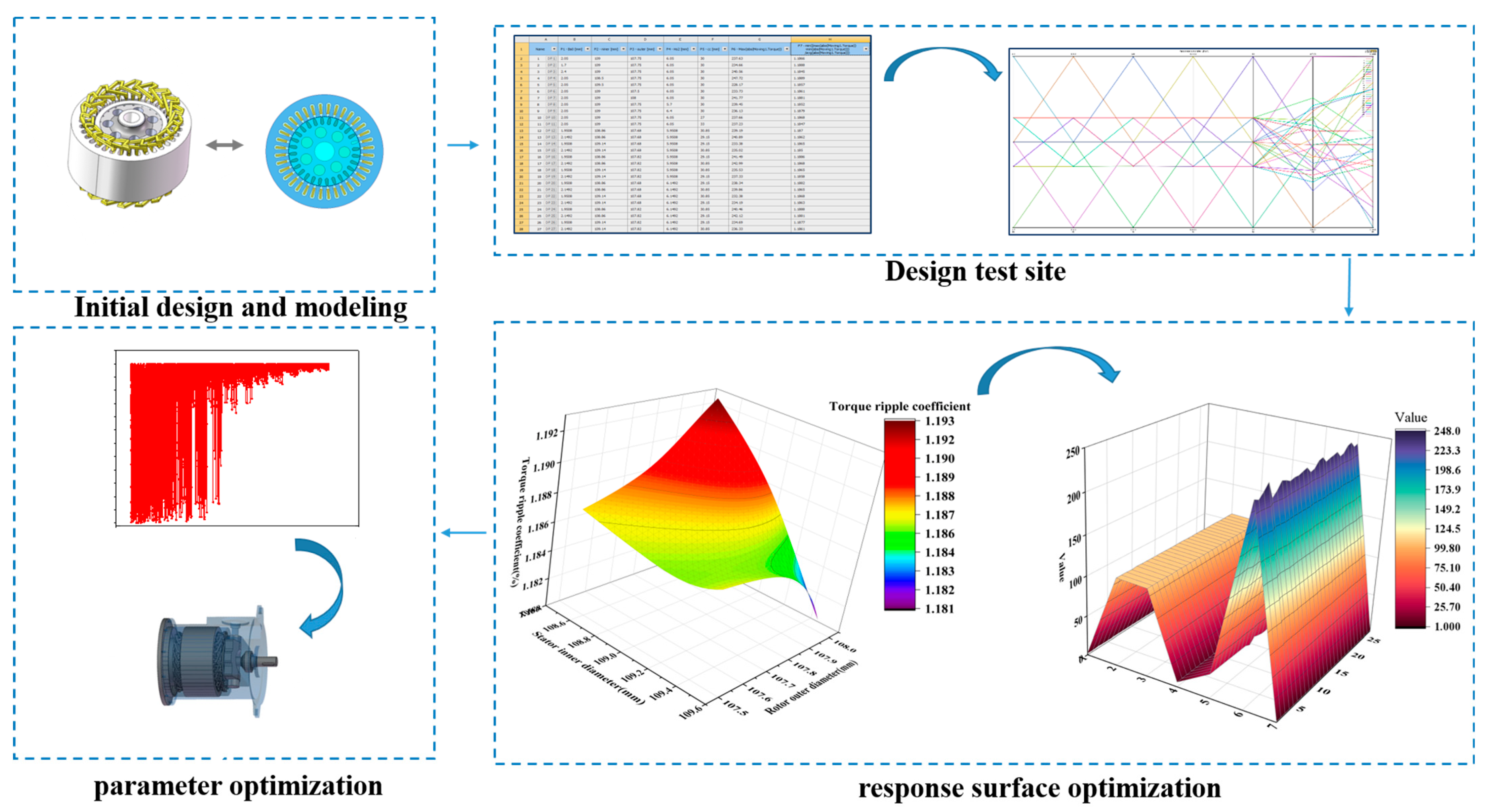
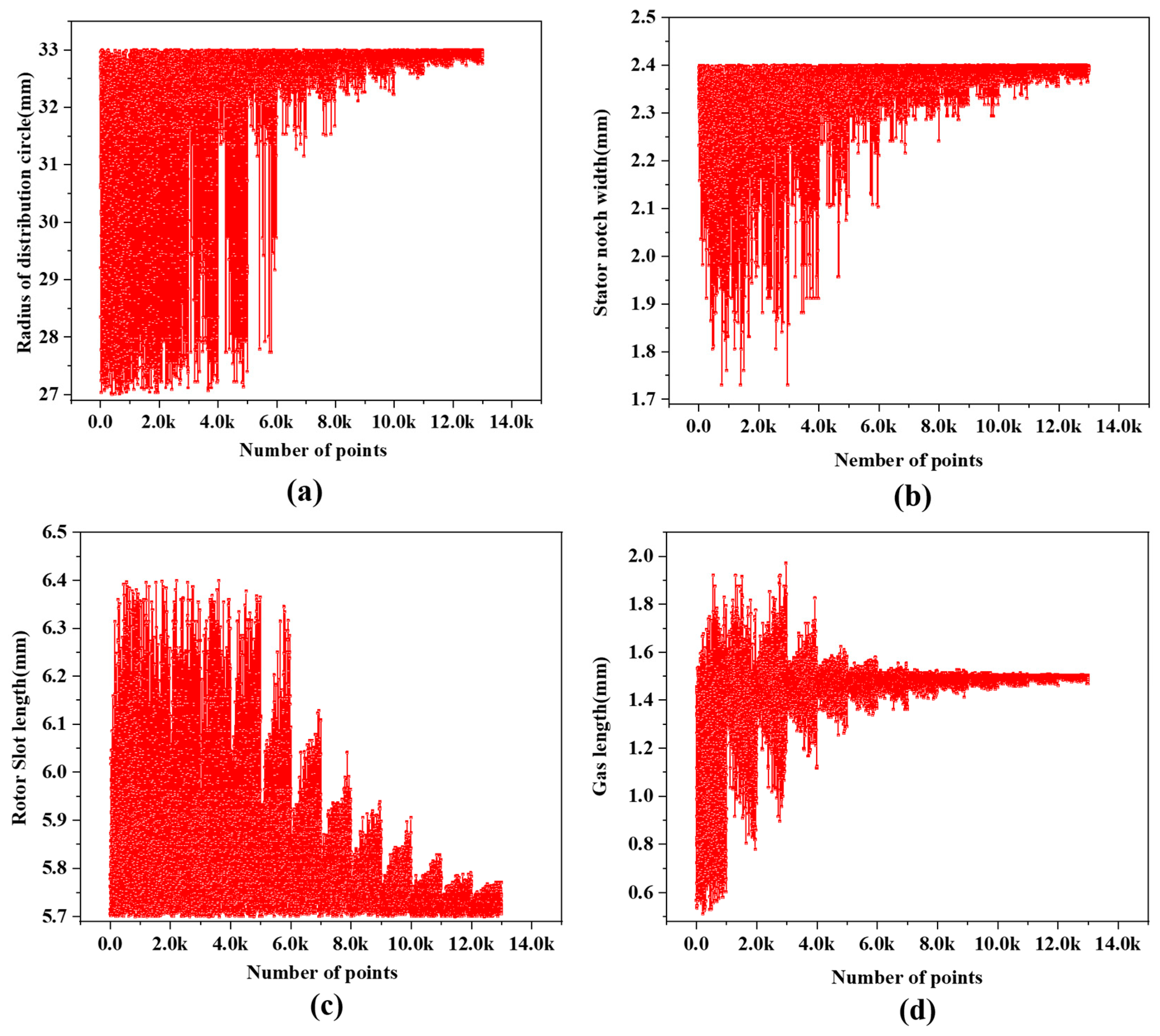
3.4. Optimization Process Design

This paper uses Maxwell and Workbench co-simulation for optimization. As shown in Figure 5, after the IA-MEHPC electrodynamic 2D model was created in Maxwell using the initial parameters, it was imported into Workbench and connected to the response surface optimization board. The range of variation in the optimization variables was first preset, as shown in Table 2, and the experimental design was carried out according to the range of variation. The peak torque and torque fluctuation values for a series of test points were obtained through simulation, generating the torque response surface optimization model. Finally, the parameters were optimized to obtain a set of optimized target parameters.
The peak torque and ripple torque coefficient response surface approximation model designed in this paper not only reduces the call to the simulation program and improves the computational efficiency. This model accurately fits the response relationship between the variables and the optimization objective with good robustness.
In this paper, 27 sets of optimized test variables were set up in Workbench according to the optimization range of the four variables and then simulated jointly with Maxwell to obtain simulation results for each set of test variables, as shown in Table 3.
Based on the test data in Table 3, the torque and torque fluctuation diagrams of the test points are drawn in this paper, as shown in Figure 6.
The response surface optimization model for peak torque and the response surface optimization model for torque fluctuation coefficient were generated from the simulation results of the experimental variables and are shown in Figure 7 and Figure 8, respectively.
Figure 7a shows the peak torque for the radius of the distribution circle and rotor slot length, which shows that the peak torque decreases with increasing rotor slot length. Figure 7b shows the peak torque for the rotor slot length and stator. The peak torque is plotted against the rotor slot length and the stator notch width combined. Figure 7c shows the response surface model of peak torque under the joint action of the radius of the distribution circle and stator notch width. Figure 7d shows the response surface model of peak torque under the rotor outer and stator inner diameter joint action.
Figure 8a shows the response surface curve of the torque ripple coefficient under the joint action of the radius of the distribution circle and rotor slot length; from the figure, we can see that the torque ripple coefficient increases with the increase in the radius of the distribution circle and rotor slot length. The graph shows that the Torque ripple coefficient increases with the increase in the radius of the distribution circle and rotor slot length, and using a large radius of the distribution circle and rotor slot length is not conducive to the stable output of motor torque. Figure 8b shows the torque ripple coefficient for the combined effect of the rotor slot length and stator notch width. It can be seen that the torque ripple coefficient increases with the increase in stator notch width; a too-large or too-small slot size produces a too-high torque pulsation, and the torque output will not be stable, which affects the motor performance. Figure 8c shows the torque ripple coefficient of the stator notch width and the radius of the distribution circle. The stator notch width and the radius of the distribution circle effect are shown in the torque ripple coefficient response surface curve graph. Figure 8d shows the air gap on the influence of the torque pulsation coefficient, which demonstrates that a too-small air gap makes the motor operation unstable.
Parameter optimization is a process of finding the optimum in a large amount of data. Figure 9 shows the test points of the four optimization variables in the optimization process. After tens of thousands of tests, the target structural parameters were finally determined.

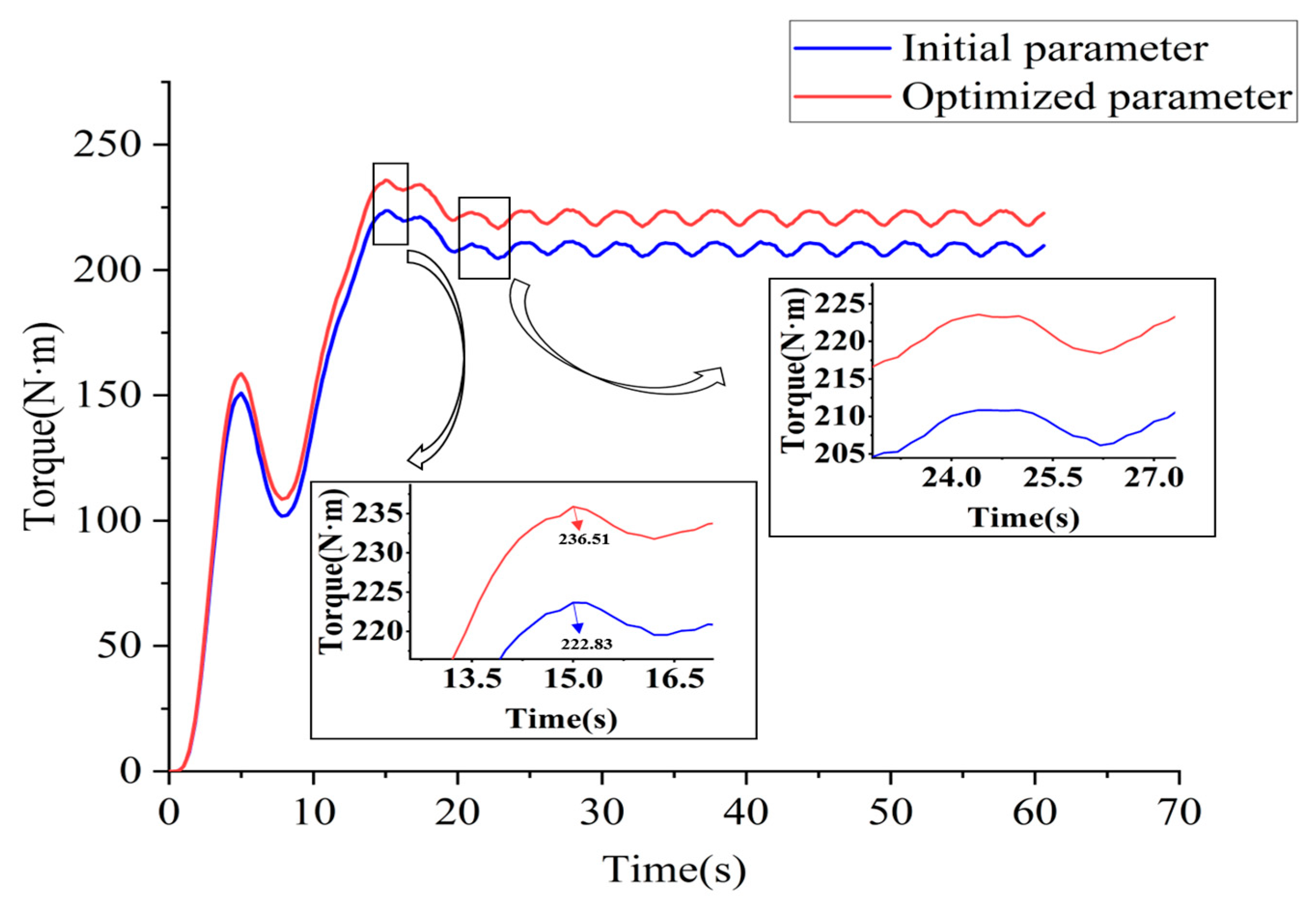
4. Optimization Results and Analysis

After fitting the response surface model, we optimized four sets of variables and obtained a series of optimization points, as shown in Figure 10, where the ideal optimization results were selected considering peak torque and torque pulsation, which led to an optimized set of parameters.
After optimization of the response surface parameters, a new set of IA-MEHPC electrical and structural parameters was obtained, as shown in Table 4.
We imported the new parameters into Maxwell for finite element analysis and compared them with the results obtained with the initial structural parameters. As can be seen from Figure 11, the simulation results show that the peak torque of the IA-MEHPC has increased by 5.78%, and the motor torque pulsation coefficient has been reduced by 15.83% after the parameter optimization, thus indicating that the electrodynamic part of the IA-MEHPC has improved its electrodynamic performance while ensuring regular torque output.
Figure 11 shows the comparison of torque before and after parameter optimization. As can be seen from the figure, the overall electrodynamic torque has increased after optimization compared to the initial parameters, with the peak torque increasing from the initial 236.51 N·m to 222.83 N·m, an increase of 5.78%.
Motor torque pulsation refers to the irregular torque output during the operation of a motor where the torque is sometimes large and sometimes small. The magnitude of torque pulsation is measured by the torque pulsation coefficient, which is calculated by the following equation:
K m = T max T min T max + T min × 100 %
Km is the torque pulsation coefficient, and Tmax and Tmin are the maximum and minimum instantaneous torque under stability.
It can be seen from Figure 11 that the curve after parameter optimization is smoother than that of the initial parameters, indicating that the electrodynamic torque output is more stable. The initial Km calculated from the torque pulsation coefficient formula is 1.39%, and the optimized Km is 1.17%, a reduction of 15.83%.
Figure 12 compares the flux density of the electrodynamic structure before and after optimization. It can be seen that the overall flux density of the optimized motor decreases, especially at the notches, reducing the magnetic loss and verifying the reasonableness of the optimized parameters.
It can be seen from the simulation results that the optimized parameters make IA-MEHPC more reasonable in structure and improve the motor performance of IA-MEHPC.

5. Conclusions

In response to the problems of considerable size, loose structure, and low efficiency of energy conversion of conventional multi-source power coupling devices, a multi-source power coupling device based on an induction asynchronous motor and a swashplate axial piston pump, IA-MEHPC, is proposed. IA-MEHPC uses an inlay model in which the piston pump’s piston is embedded in the motor’s rotor, thus making the overall structure compact and reducing installation difficulties. In this paper, the structural principle of the IA-MEHPC and its application to a complete vehicle was described in detail, and a 3D model was built. The original parameters of the IA-MEHPC were used to build a 2D model of its electrodynamic structure in Maxwell, and a joint simulation between Maxwell and Workbench was realized. Based on the response surface optimization method, the air gap, stator slot width, plunger whole distribution circle radius, and rotor slot axial length were optimized to improve the performance of the IA-MEHPC. The simulation validation shows that the peak motor torque of the optimized IA-MEHPC is increased by 5.78%, and the torque pulsation coefficient is reduced by 15.83%, which is in line with engineering practice expectations.
This paper gives an idea for the design and optimization study of a new multi-source power coupling device type. The research in this paper provides a reference for motor performance optimization. It enables the electro–mechanical–hydraulic coupling to move formally from the simulation to the physical stage. It is significant for improving and researching multi-source power coupling devices. In the future, hardware-in-the-loop and actual vehicle experiments will be carried out to verify the broad applicability of the related research.

Author Contributions

Conceptualization, H.C.; Software, J.W. and Z.Z.; Resources, T.Z.; Writing—original draft, J.W.; Writing—review & editing, J.W.; Supervision, J.W. and H.Z.; Funding acquisition, H.Z. All authors have read and agreed to the published version of the manuscript.

Funding

This research was funded by the National Natural Science Foundation of China, grant number 52075278, and the Municipal Livelihood Science and Technology Project of Qingdao, grant number 19-6-1-92-nsh.

Data Availability Statement

The data presented in this study are available in the main text.

Conflicts of Interest

The authors declare no conflict of interest.

References

  1. Yang, J.; Liu, B.; Zhang, T.; Hong, J.; Zhang, H. Multi-parameter controlled mechatronics-electro-hydraulic power coupling electric vehicle based on active energy regulation. Energy 2023, 263, 125877. [Google Scholar] [CrossRef]
  2. Hong, J.; Wang, Z.; Yao, Y. Fault prognosis of battery system based on accurate voltage abnormity prognosis using long short-term memory neural networks. Appl. Energy 2019, 251, 113381. [Google Scholar] [CrossRef]
  3. Amjad, S.; Neelakrishnan, S.; Rudramoorthy, R. Review of design considerations and technological challenges for successful development and deployment of plug-in hybrid electric vehicles. Renew. Sustain. Energy Rev. 2010, 14, 1104–1110. [Google Scholar] [CrossRef]
  4. Hong, J.; Ma, F.; Xu, X.; Yang, J.; Zhang, H. A novel mechanical-electric-hydraulic power coupling electric vehicle considering different electrohydraulic distribution ratios. Energy Convers. Manag. 2021, 249, 114870. [Google Scholar] [CrossRef]
  5. Yang, J.; Zhang, T.; Zhang, H.; Hong, J.; Meng, Z. Research on the starting acceleration characteristics of a new mechanical–electric–hydraulic power coupling electric vehicle. Energies 2020, 13, 6279. [Google Scholar] [CrossRef]
  6. Niu, G.; Shang, F.; Krishnamurthy, M.; Garcia, J.M. Design and Analysis of an Electric Hydraulic Hybrid Powertrain in Electric Vehicles. IEEE Trans. Transp. Electrif. 2017, 3, 48–57. [Google Scholar] [CrossRef]
  7. Li, Z.; Zheng, L.; Ren, Y.; Li, Y.; Xiong, Z. Multi-objective optimization of active suspension system in electric vehicle with In-Wheel-Motor against the negative electromechanical coupling effects. Mech. Syst. Signal Process. 2019, 116, 545–565. [Google Scholar] [CrossRef]
  8. Hu, J.; Peng, T.; Jia, M.; Yang, Y.; Guan, Y. Study on Electromechanical Coupling Characteristics of an Integrated Electric Drive System for Electric Vehicle. IEEE Access 2019, 7, 166493–166508. [Google Scholar] [CrossRef]
  9. Line, C.; Manzie, C.; Good, M.C. Electromechanical Brake Modeling and Control: From PI to MPC. IEEE Trans. Control Syst. Technol. 2008, 16, 446–457. [Google Scholar] [CrossRef]
  10. Li, Z.; Zheng, L.; Gao, W.; Zhan, Z. Electromechanical coupling mechanism and control strategy for in-wheel motor driven electric vehicles. IEEE Trans. Ind. Electron. 2018, 66, 4524–4533. [Google Scholar] [CrossRef]
  11. Hui, S.; Lifu, Y.; Junqing, J.; Yanling, L. Control strategy of hydraulic/electric synergy system in heavy hybrid vehicles. Energy Convers. Manag. 2011, 52, 668–674. [Google Scholar] [CrossRef]
  12. Yang, J.; Liu, B.; Zhang, T.; Hong, J.; Zhang, H. Application of energy conversion and integration technologies based on electro-hydraulic hybrid power systems: A review. Energy Convers. Manag. 2022, 272, 116372. [Google Scholar] [CrossRef]
  13. Wang, F.; Lin, Z.; Xu, B.; Fiebig, W. An Electric-Hydrostatic Energy Storage System for Hydraulic Hybrid Wheel Loader. IEEE Trans. Veh. Technol. 2022, 71, 7044–7056. [Google Scholar] [CrossRef]
  14. Chen, J.-S. Energy Efficiency Comparison between Hydraulic Hybrid and Hybrid Electric Vehicles. Energies 2015, 8, 4697–4723. [Google Scholar] [CrossRef] [Green Version]
  15. Wu, W.; Hu, J.; Yuan, S.; Di, C. A hydraulic hybrid propulsion method for automobiles with self-adaptive system. Energy 2016, 114, 683–692. [Google Scholar] [CrossRef]
  16. Zhang, Z.; Zhang, T.; Hong, J.; Zhang, H.; Yang, J. Energy management strategy of a novel parallel electric-hydraulic hybrid electric vehicle based on deep reinforcement learning and entropy evaluation. J. Clean. Prod. 2023, 403, 136800. [Google Scholar] [CrossRef]
  17. Hui, S.; Lifu, Y.; Junqing, J. Hydraulic/electric synergy system (HESS) design for heavy hybrid vehicles. Energy 2010, 35, 5328–5335. [Google Scholar] [CrossRef]
  18. El-Kharashi, E.; El-Dessouki, M. Coupling induction motors to improve the energy conversion process during balanced and unbalanced operation. Energy 2014, 65, 511–516. [Google Scholar] [CrossRef]
  19. Islam, M.S.; Islam, R.; Sebastian, T. Experimental verification of design techniques of permanent-magnet synchronous motors for low-torque-ripple applications. IEEE Trans. Ind. Appl. 2010, 47, 88–95. [Google Scholar] [CrossRef]
  20. Shyu, K.K.; Lin, J.K.; Pham, V.T.; Yang, M.J.; Wang, T.W. Global minimum torque ripple design for direct torque control of induction motor drives. IEEE Trans. Ind. Electron. 2009, 57, 3148–3156. [Google Scholar] [CrossRef]
  21. Hao, Z.; Yu, Q.; Cao, X.; Deng, X.; Shen, X. An improved direct torque control for a single-winding bearingless switched reluctance motor. IEEE Trans. Energy Convers. 2020, 35, 1381–1393. [Google Scholar] [CrossRef]
  22. Duan, F.; Živanović, R.; Al-Sarawi, S.; Mba, D. Induction motor parameter estimation using sparse grid optimization algorithm. IEEE Trans. Ind. Inform. 2016, 12, 1453–1461. [Google Scholar] [CrossRef]
  23. Zhou, J.; Cheng, M.; Wen, H.; Yan, X.; Tong, M.; Wang, W. Modeling and Suppression of Torque Ripple in PMSM Based on the General Airgap Field Modulation Theory. IEEE Trans. Power Electron. 2022, 37, 12502–12512. [Google Scholar] [CrossRef]
  24. Zhu, X.; Yang, J.; Xiang, Z.; Jiang, M.; Zheng, S.; Quan, L. Robust-oriented optimization design for permanent magnet motors considering parameter fluctuation. IEEE Trans. Energy Convers. 2020, 35, 2066–2075. [Google Scholar] [CrossRef]
  25. Ertan, H.B.; Dag, B.; Capolino, G.A. Calculation of parameters of single-phase PM motor for design optimization. IEEE Trans. Energy Convers. 2005, 20, 538–548. [Google Scholar] [CrossRef]
  26. Qiu, H.; Duan, H. Multi-objective pigeon-inspired optimization for brushless direct current motor parameter design. Sci. China Technol. Sci. 2015, 58, 1915–1923. [Google Scholar] [CrossRef]
  27. Kucukkoc, I.; Karaoglan, A.D.; Yaman, R. Using response surface design to determine the optimal parameters of genetic algorithm and a case study. Int. J. Prod. Res. 2013, 51, 5039–5054. [Google Scholar] [CrossRef] [Green Version]
  28. Bakhtiari, H.; Karimi, M.; Rezazadeh, S. Modeling, analysis and multi-objective optimization of twist extrusion process using predictive models and meta-heuristic approaches, based on finite element results. J. Intell. Manuf. 2016, 27, 463–473. [Google Scholar] [CrossRef]
  29. Todoroki, A.; Ishikawa, T. Design of experiments for stacking sequence optimizations with genetic algorithm using response surface approximation. Compos. Struct. 2004, 64, 349–357. [Google Scholar] [CrossRef]
Figure 1. Structure schematic diagram of IA-MEHPC: (a) IA-MEHPC overall structure diagram; (b) electrical structure of IA-MEHPC.
Processes 11 02217 g001
Figure 2. Schematic diagram of the IV-MEHPC on HV.
Processes 11 02217 g002
Figure 3. Finite element two-dimensional model of the IV-MEHPC electrical structure.
Processes 11 02217 g003
Figure 4. IV-MEHPC electrical optimization parameters.
Processes 11 02217 g004
Figure 5. IV-MEHPC electrical structure parameter optimization process based on response surface.
Processes 11 02217 g005
Figure 6. Simulation results of test variables.
Processes 11 02217 g006
Figure 7. Peak torque response surface optimization model: (a) peak torque under the radius of the distribution circle and rotor slot length joint action; (b) Peak torque under the rotor slot length and stator joint action; (c) Peak torque under the radius of the distribution circle and stator notch width joint action; (d) Peak torque under the rotor out-er and stator inner diameter joint action.
Processes 11 02217 g007
Figure 8. Torque pulsation coefficient response surface optimization model: (a) Torque ripple coefficient under the radius of the distribution circle and rotor slot length joint action; (b) Torque ripple coefficient under the rotor slot length and stator joint action; (c) Torque ripple coefficient under the radius of the distribution circle and stator notch width joint action; (d) Torque ripple coefficient under the rotor outer and stator inner diameter joint action.
Processes 11 02217 g008aProcesses 11 02217 g008b
Figure 9. Test point of optimization variables: (a) Test points of radius of distribution circle; (b) Test points of stator notch width; (c) Test points of rotor slot length; (d) Test points of gas length.
Processes 11 02217 g009
Figure 10. Tradeoff chart of peak torque and torque ripple coefficient.
Processes 11 02217 g010
Figure 11. Comparison of torque before and after parameter optimization.
Processes 11 02217 g011
Figure 12. Comparison of magnetic flux density of IV-MEHPC electric structure before and after optimization. (a) Before optimization. (b) Postoptimality.
Processes 11 02217 g012
Table 1. Initial design parameters of IV-MEHPC electrical structure.
ParameterValues
Number of slots/pole pairs36/3
Number of plunger holes7
Stator core length/mm84
Diameter of plunger/mm17
Distribution diameter/mm30
Gas length/mm0.75
Number of slots/pole pairs36/3
Table 2. Initial values and range of variation in parameters to be optimized for the electrical structure.
ParameterInitial ValueVariation Range
Gas length/mm0.750.25~1
Stator notch width/mm1.71.53~1.87
Rotor Slot length/mm65.2~6.6
Radius of distribution circle/mm3027~33
Table 3. Test variable simulation results.
Point1 Bs0/mm2 Hs2/mmGas Length/mm3 R/mmTorque
/N·m
Ripple Torque Coefficient/%
12.056.050.62530237.631.1866
21.76.050.62530234.661.1888
32.46.050.62530240.561.1845
42.056.050.37530247.721.1889
52.056.050.87530228.171.1857
62.056.050.7530233.731.1861
72.056.050.530241.771.1881
82.055.70.62530239.451.1852
92.056.40.62530236.131.1879
102.056.050.62527237.661.1868
112.056.050.62533237.231.1847
121.95085.95080.5930.85239.191.187
132.14925.95080.5929.15240.891.1862
141.95085.95080.7329.15233.381.1865
152.14925.95080.7330.85235.021.185
161.95085.95080.5229.15241.491.1886
172.14925.95080.5230.85242.991.1868
181.95085.95080.6630.85235.531.1865
192.14925.95080.6629.15237.331.1858
201.95086.14920.5929.15238.341.1882
212.14926.14920.5930.85239.861.1865
221.95086.14920.7330.85232.381.1868
232.14926.14920.7329.15234.191.1863
241.95086.14920.5230.85240.461.1888
252.14926.14920.5229.15242.121.1881
261.95086.14920.6629.15234.691.1877
272.14926.14920.6630.85236.331.1861
1 Bs0 is the stator notch width. 2 Hs2 is the rotor slot length. 3 R is the radius of distribution circle.
Table 4. Optimized parameters of the electrical structure.
ParameterOptimized Value
Gas length/mm0.7
Stator notch width/mm2.3994
Rotor Slot length/mm5.7058
Radius of distribution circle/mm32.95
Disclaimer/Publisher’s Note: The statements, opinions and data contained in all publications are solely those of the individual author(s) and contributor(s) and not of MDPI and/or the editor(s). MDPI and/or the editor(s) disclaim responsibility for any injury to people or property resulting from any ideas, methods, instructions or products referred to in the content.

